

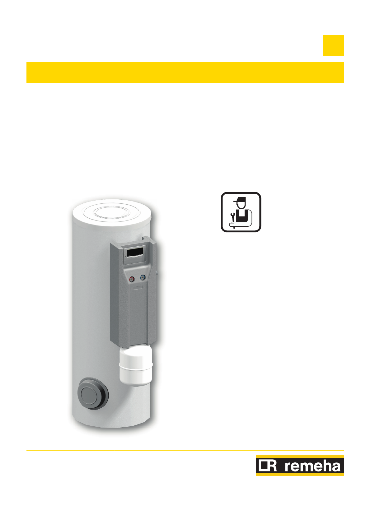
RemaSol
L000541-B
Solar hot water calorifer
200SE-2S - 300SE-2S
EN
Installation and
Service Manual
7607575-05
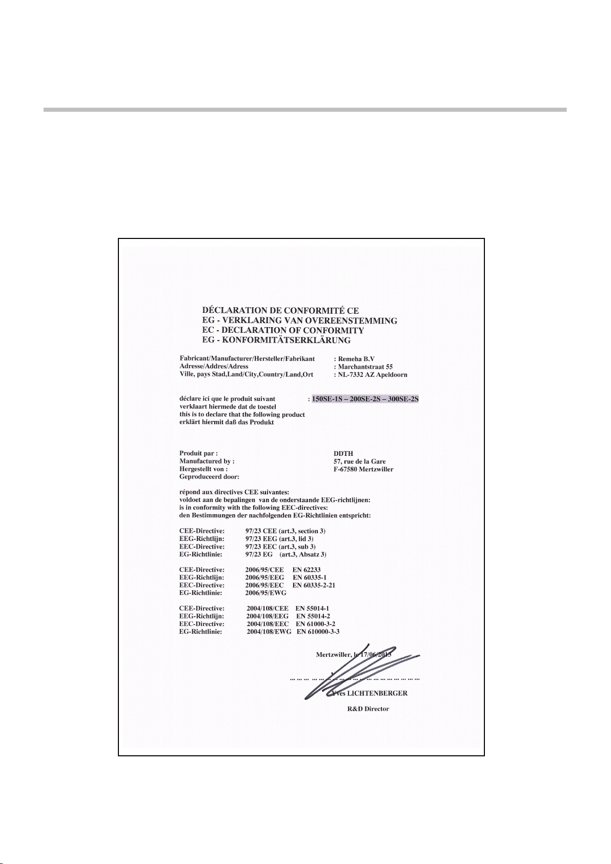
Declaration of conformity [
M003220-A
The device complies with the standard type described in
the EG declaration of conformity. It was manufactured and
commissioned in accordance with European directives.
The original declaration of conformity is available from the
manufacturer.

Contents
1 Safety instructions .....................................................................................6
1.1 Safety instructions ...............................................6
1.2 Recommendations ................................................8
1.3 Liabilities ...............................................................9
1.3.1 Manufacturer’s liability .............................................9
1.3.2 Installer’s liability ...................................................10
2 About this manual ....................................................................................11
2.1 Symbols used .....................................................11
2.1.1 Symbols used in the manual .................................11
2.1.2 Symbols used on the equipment ...........................11
2.2 Abbreviations ......................................................11
3 Technical description ..............................................................................12
3.1 Homologations ....................................................12
3.1.1 Certifications .........................................................12
3.1.2 Directive 97/23/EC ................................................12
3.2 General description ............................................12
3.3 Main parts ............................................................13
3.3.1 Solar domestic hot water calorifier ........................13
3.3.2 Solar station ..........................................................14
3.3.3 Solar regulator .......................................................14
3.4 Operating principle .............................................14
3.4.1 General principle ...................................................15
3.4.2 Protection against overheating on the solar
circuit .....................................................................16
3.5 Technical specifications ....................................16
3.5.1 Solar domestic hot water calorifier ........................16
3.5.2 Sensor characteristics ...........................................17
3.5.3 Solar regulator .......................................................17
3.5.4 Solar station ..........................................................18
4 Installation ................................................................................................19
4.1 Regulations governing installation ...................19
4.2 Package list .........................................................19
4.2.1 Standard delivery ..................................................19
26/04/2016 - 7607575-05
1

Contents
4.3 Choice of the location ........................................20
4.3.1 Type plate .............................................................20
4.3.2 Positioning of the appliance ..................................20
4.3.3 Main dimensions ...................................................21
4.4 Positioning the appliance ..................................22
4.5 Levelling ..............................................................22
4.6 Installing the temperature sensors ...................22
4.7 Hydraulic installation diagrams ........................23
4.7.1 Boiler for heating only (Output <45 kW) +
200/300SE-2S ......................................................23
4.7.2 Combi boiler + 200/300SE-2S .............................24
4.7.3 Combi boiler + Additional heating (Output <45 kW) +
200/300SE-2S ......................................................25
4.8 Safety unit ...........................................................26
4.9 Hydraulic connections .......................................27
4.9.1 Primary solar circuit ...............................................27
4.9.2 Primary heating circuit ...........................................31
4.9.3 Connecting the calorifer to the domestic water circuit
(secondary circuit) .................................................31
4.10 Electrical connections ........................................33
4.10.1 Recommendations ................................................33
4.10.2 Connecting the solar control system .....................34
4.10.3 Electrical diagram ..................................................34
4.10.4 Connecting the resistor .........................................36
4.10.5 Connecting the circulation pump ...........................37
4.11 Filling the DHW calorifer ....................................37
4.11.1 Drinking water quality ............................................37
4.12 Filling the primary solar circuit .........................38
4.12.1 Flowmeter .............................................................38
4.12.2 Anti-thermosiphon valve ........................................39
4.12.3 Filling the primary solar circuit ...............................39
4.13 Filling the heating circuit ...................................43
5 Commissioning ........................................................................................44
26/04/2016 - 7607575-05
5.1 Control panels .....................................................44
5.1.1 Description of the keys ..........................................44
5.1.2 Description of the display ......................................44
5.2 Check points before commissioning ................46
5.2.1 Domestic hot water calorifer ..................................46
5.2.2 Primary solar circuit ...............................................46
5.2.3 Primary heating circuit ...........................................46
5.2.4 Electrical connection .............................................46
2

5.3 Commissioning procedure ................................47
5.3.1 Secondary circuit (domestic water) .......................47
5.3.2 Primary solar circuit ...............................................47
5.4 Reading out measured values ...........................48
5.4.1 Resetting the values to zero ..................................48
5.5 Installer parameters ............................................49
5.5.1 Modifying the installer parameters ........................49
5.5.2 List of the parameters ...........................................49
5.5.3 Description of the installer parameters ..................51
6 Checking and maintenance .....................................................................56
6.1 General instructions ...........................................56
6.2 Safety valve or safety unit .................................56
6.3 Cleaning the casing material .............................56
6.4 Checking the magnesium anode .......................56
6.5 Descaling .............................................................57
6.6 Removing and remounting the inspection
hatches ................................................................57
6.6.1 Removing the inspection hatches .........................57
6.6.2 Remounting the inspection hatches ......................58
6.7 Inspection and maintenance of the solar
circuit ...................................................................59
6.7.1 Maintenance operations to be performed .............59
6.7.2 Adding heat transporting fluid ...............................59
6.8 Maintenance form ...............................................60
6.9 Installation report ...............................................62
7 Troubleshooting .......................................................................................64
7.1 Electricity supply ................................................64
7.2 Sensor fault .........................................................64
7.3 Incidents and solutions ......................................65
8 Spare parts ................................................................................................66
8.1 General ................................................................66
8.2 Spare parts ..........................................................67
8.2.1 Domestic hot water tanks ......................................67
8.2.2 Solar station ..........................................................69
8.2.3 Electric heating resistance For 200/400) only .......71
26/04/2016 - 7607575-05
3

9 Appendix – Information on the Ecodesign and Energy Labelling
Directives ..................................................................................................72
Contents
26/04/2016 - 7607575-05
4

26/04/2016 - 7607575-05
5
1. Safety instructions 200SE-2S - 300SE-2S
1 Safety instructions
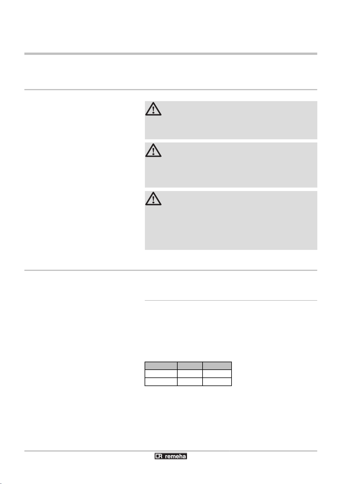
1.1 Safety instructions
DANGER
This appliance can be used by children aged
from 8 years and above and persons with
reduced physical, sensory or mental capabilities
or lack of experience and knowledge if they have
been given supervision or instruction concerning
use of the appliance in a safe way and
understand the hazards involved. Children shall
not play with the appliance. Cleaning and user
maintenance shall not be made by children
without supervision.
CAUTION
1. Turn off the domestic cold water inlet.
2. Open a hot water tap on the installation.
3. Open a safety unit valve.
4. When the water stops flowing, the appliance
has been drained.
6
26/04/2016 - 7607575-05
200SE-2S - 300SE-2S 1. Safety instructions
CAUTION
Pressure limiter device
4 The pressure limiter device (safety valve or
safety unit) must be operated regularly in
order to clear out any limescale deposits and
ensure that it is not blocked.
4 The pressure limiter device must be
connected to a discharge pipe.
4 As water may flow from the discharge pipe,
it must be kept open to the air, in a frost-free
environment, in a continuous downward
gradient.
For the type, characteristics and connection of
the pressure limiter device, please refer to the
section entitled Connecting the domestic hot
water tank to the drinking water network in the
installation and service manual for the domestic
hot water tank.
The user guide and the installation manual can
also be found on our internet site.
CAUTION
Allowance must be made for a means of
disconnection in the fixed pipes in accordance
with the regulations on installations.
CAUTION
If a power cord is provided with the appliance
and it turns out to be damaged, it must be
replaced by the manufacturer, its after sales
service or persons with similar qualifications in
order to obviate any danger.
26/04/2016 - 7607575-05
7

1. Safety instructions
1.2 Recommendations
200SE-2S - 300SE-2S
CAUTION
Respect the maximum water inlet pressure to
ensure correct operation of the appliance,
referring to the chapter "Technical
Specifications".
CAUTION
Before any work, switch off the mains supply to
the appliance.
CAUTION
In order to limit the risk of being scalded, the
installation of a thermostatic mixing valve on the
domestic hot water flow piping is compulsory.
CAUTION
Do not neglect to service the appliance. Service
the appliance regularly to ensure that it operates
correctly.
WARNING
Only qualified professionals are authorised to
work on the appliance and the installation.
WARNING
4 The heating water and the water-propylene-
glycol mixture must not come into contact
with the domestic hot water.
4 The domestic hot water must not circulate
through an exchanger.
4 Solar installations can be protected against
lighting and must be earthed or connected
to an equipotential connection.
To take advantage of the guarantee, no modifications
must be made to the appliance. Only remove the covers
for maintenance and breakdown repair operations and put
the covers back in place after the maintenance and
breakdown repair operations.
Instructions stickers
8
26/04/2016 - 7607575-05
200SE-2S - 300SE-2S
1. Safety instructions
The instructions and warnings affixed to the appliance
must never be removed or covered and must remain
legible during the entire lifespan of the appliance.
Immediately replace damaged or illegible instructions and
warning stickers.
WARNING
Never cut the power to the solar control system,
even during extended absences. The control
system protects the installation against
overheating in summer when it is running.
WARNING
Do not modify the control system parameters
unless fully conversant with them.
During extended absences, we recommend lowering the
set point temperature in the solar DHW calorifier to 45°C.
When the user is present, the set point must be set to
60°C.
1.3 Liabilities
1.3.1. Manufacturer’s liability
Our products are manufactured in compliance with the
requirements of the various applicable European
Directives. They are therefore delivered with [ marking
and all relevant documentation.
In the interest of customers, we are continuously
endeavouring to make improvements in product quality.
All the specifications stated in this document are therefore
subject to change without notice.
Our liability as the manufacturer may not be invoked in the
following cases:
4 Failure to abide by the instructions on using the
appliance.
4 Faulty or insufficient maintenance of the appliance.
26/04/2016 - 7607575-05
4 Failure to abide by the instructions on installing the
appliance.
9

1. Safety instructions 200SE-2S - 300SE-2S
1.3.2. Installer’s liability
The installer is responsible for the installation and
commissioning of the appliance. The installer must
respect the following instructions:
4 Read and follow the instructions given in the manuals
provided with the appliance.
4 Carry out installation in compliance with the prevailing
legislation and standards.
4 Perform the initial start up and carry out any checks
necessary.
4 Explain the installation to the user.
4 If a maintenance is necessary, warn the user of the
obligation to check the appliance and maintain it in
good working order.
4 Give all the instruction manuals to the user.
10
26/04/2016 - 7607575-05
200SE-2S - 300SE-2S
2 About this manual
2.1 Symbols used
2.1.1. Symbols used in the manual
In these instructions, various danger levels are employed to draw the
user’s attention to particular information. In so doing, we wish to
safeguard the user’s safety, highlight hazards and guarantee correct
operation of the appliance.
2. About this manual
DANGER
Risk of a dangerous situation causing serious physical
injury.
WARNING
Risk of a dangerous situation causing slight physical
injury.
CAUTION
Risk of material damage.
Signals important information.
¼Signals a referral to other instructions or other pages in the
instructions.
2.1.2. Symbols used on the equipment
Before installing and commissioning the device, read
carefully the instruction manuals provided.
Dispose of the used products in an appropriate recovery
and recycling structure.
2.2 Abbreviations
26/04/2016 - 7607575-05
4 CFC: Chlorofluorocarbon
4 DHW: Domestic hot water
11

3. Technical description
3 Technical description
3.1 Homologations
3.1.1. Certifications
This product complies to the requirements to the european directives
and following standards:
4 PHRASE NON TRADUITE : 65228 .
Reference Standard: EN 60.335.1.
Reference Standard: EN 60.335.2.21.
4 PHRASE NON TRADUITE : 65229 .
Reference Standards: EN 50.081.1, EN 50.082.1, EN 55.014
200SE-2S - 300SE-2S
3.2 General description
3.1.2. Directive 97/23/EC
This product conforms to the requirements of european directive 97 /
23 / EC, article 3, paragraph 3, on pressure equipment.
200SE-2S - 300SE-2S domestic hot water calorifiers are connected
to solar collectors by a solar station.
The calorifiers 200SE-2S - 300SE-2S are fully equipped with a solar
technical station, consisting of a charge device for each zone, a safety
device, an expansion vessel, a pump, a solar control system Delta
Sol AEL etc.
Main parts:
4 The tanks are made of high quality steel lined with food quality
standard enamel vitrified at 850°C, which protects the tank from
corrosion.
4 The heat exchangers welded into the tank are made of smooth
piping, the external surface of which, in contact with the drinking
water, is enamelled.
4 The appliance is highly insulated with CFC-free polyurethane
foam, which reduces thermal losses to a minimum.
4 The external casing is made of ABS.
4 The tanks are protected against corrosion by several magnesium
anodes.
12
26/04/2016 - 7607575-05
L000430-C
5
7
4
6
1
2
3
L000598-A
4
2
1
3
200SE-2S - 300SE-2S 3. Technical description
3.3 Main parts
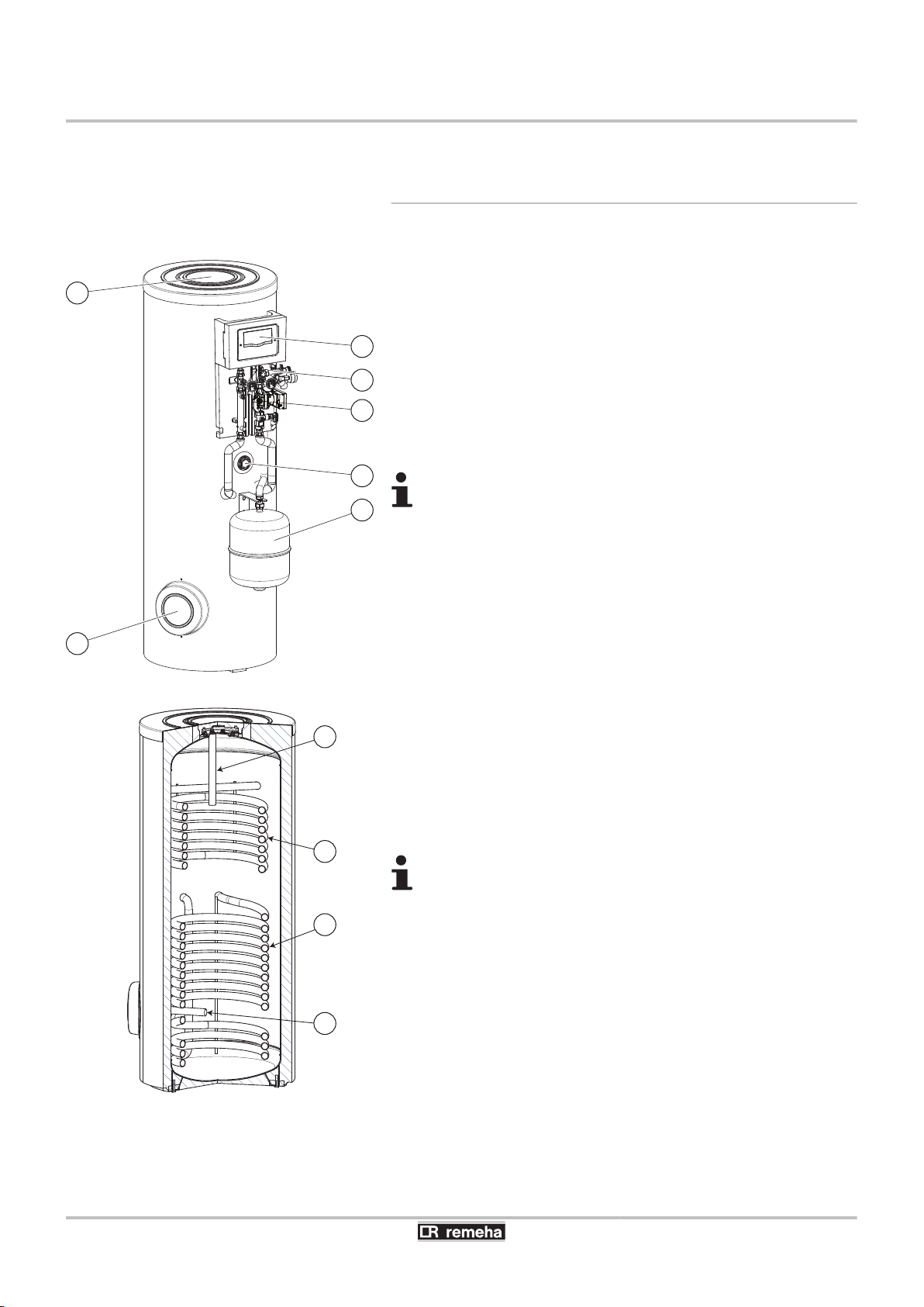
3.3.1. Solar domestic hot water calorifier
200SE-2S - 300SE-2S: External view
A
Z
E
R
T
Y
U
200SE-2S - 300SE-2S: Internal view
A
Z
Expansion vessel
Top inspection trap
Side inspection plate
Solar station
Solar regulator
Electrical back-up (Option)
Safety control unit for the solar circuit
All components are checked for leaks and tested in the
factory. The control system, the pump and the electrical
back-up are pre-wired.
Solar exchanger
Back-up exchanger
(Boiler or heat pump)
E
R
Anode - Side inspection plate
Anode - Top inspection trap
All components are checked for leaks and tested in the
factory. The control system, the pump and the electrical
back-up are pre-wired.
26/04/2016 - 7607575-05
13
1
3
5
2
4
109
6
7
8
L000415-C
M002750-A
1
4
5
8
7
7
2
8
6
3
3. Technical description
200SE-2S - 300SE-2S
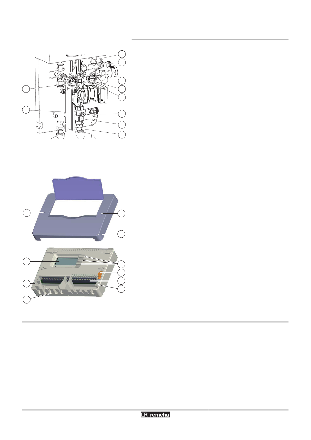
3.3.2. Solar station
A
Z
E
R
T
Y
U
I
O
P
Pressure gauge
Solar circulation pump
Filling valve
Draining valve
Safety valve
Solar circuit air vent
Flowmeter
Clamping ring fitting
Red flow thermometer
Blue flow thermometer
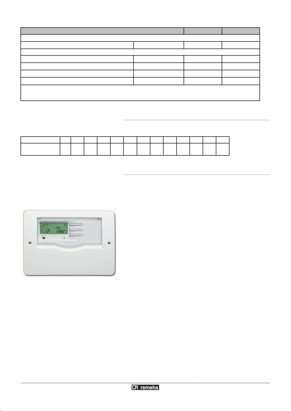
3.3.3. Solar regulator
A
Z
E
R
T
Y
U
I
Cover
Alphanumeric LCD display
Control keys
Fuse 4 AT backup
Connectors
Routing the cables
Cover screw
Hole for fixation screw
3.4 Operating principle
The solar control system optimises the collection of solar energy in
order to reheat the domestic hot water contained in the calorifier.
14
26/04/2016 - 7607575-05
TC
TR
DT
SX
PC %
CMIN
CMAX
M002751-C
1 2 3 4
5
6
7
8
°C
t
tu
200SE-2S - 300SE-2S 3. Technical description
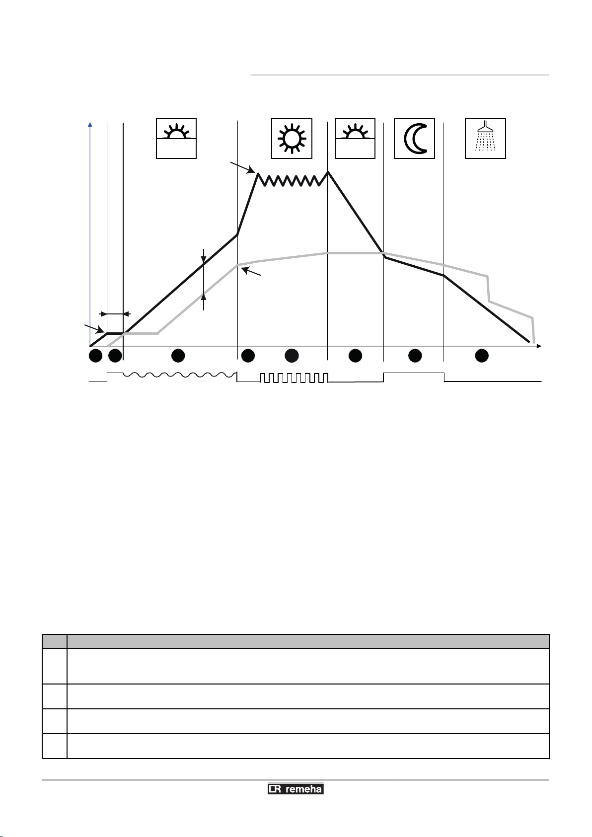
3.4.1. General principle
TC
TR
DT
SX
PC %
CMIN
CMAX
tu
°C
t
Operating description
Live
The sun’s irradiation heat the transfer fluid in the collector. To trigger the circulation pump, a minimum temperature of
1
30°C is necessary in the collectors (CMIN) as is a temperature difference of 6 K between the temperature of the collectors
and the DHW tank.
In the automatic calibration phase (setting parameter tu, factory setting 3 minutes), the solar pump (relay 1) operates on
2
full (100%) in order to stabilise the temperature in the solar circuit.
Subsequently, the rate at which the solar pump operates is calculated dynamically to maintain a reference temperature
3
difference (parameter DT, factory setting 20 K) between the collectors and the DHW tank.
The system loads the DHW tank according to the heat available in the collectors and stops when the set point temperature
4
of the DHW tank is reached (setting parameter SX, factory setting 60).
¼See chapter: "Description of the installer parameters", page
51.
Temperature of the solar collectors
Temperature of the lower part of the tank
Reference temperature difference
Set temperature of the solar calorifier
Solar circulation pump mode
Minimum collector temperature triggering the pump
Maximum temperature of the solar collector
Self-calibration time
Temperature
Time
26/04/2016 - 7607575-05
15

3. Technical description 200SE-2S - 300SE-2S
Live Operating description
When the temperature in the collectors reaches the maximum value (adjustment parameter CMAX, factory setting 110°C),
5
the solar pump is triggered to cool the collectors.
The pump continues to operate until the temperature in the collectors is lower than 5 K at parameter CMAX and/or the
maximum storage temperature (80°C) is reached in the hot water storage tank.
When there is less available sunlight, the temperature in the collectors drops and the temperature in the DHW tank is
6
stable.
As soon as the temperature in the collectors drops below the temperature in the calorifier, the calorifier is cooled down to
7
its set temperature.
When the set point SX is reached, the circulation pump shuts down, the temperature in the collectors drops again and the
8
temperature in the DHW tank falls according to any draw-offs made.
The DHW tank cooling function is inactive if using tubular
collectors (function FT active).
3.4.2. Protection against overheating on the solar
circuit
The control system has various functions, which are easy to discern
for the user, which limit overheating of the installation’s components.
3.5 Technical specifications
3.5.1. Solar domestic hot water calorifier
Primary circuit: Solar exchanger
Maximum operating temperature °C 110 110
Maximum operating pressure Mpa (bar) 1 (10) 1 (10)
Exchanger capacity litres 5.6 8.1
Exchange surface
Primary circuit: Back-up exchanger
Maximum operating temperature °C 110 110
Maximum operating pressure Mpa (bar) 1 (10) 1 (10)
Exchanger capacity litres 5.1 5.1
Exchange surface
Pressure drop at 2 m3/Time
Secondary circuit (domestic water)
Maximum operating temperature °C 95 95
Maximum operating pressure Mpa (bar) 1 (10) 1 (10)
Water content litres 225 300
Top up volume litres 75 105
Solar volume litres 150 195
Weight
Gross weight kg 125 125
Net weight kg 109 111.5
(1) Primary temperature: 80 °C - Domestic cold water inlet: 10 °C - Domestic hot water outlet: 45 °C - Primary flow rate: 2 m3/h
(2) Primary temperature: 80 °C - Domestic cold water inlet: 10 °C - Domestic hot water outlet: 40 °C - Domestic hot water storage: 65 °C
(3) Satisfies the requirements of the EN 12977–1 standard
2
m
2
m
kPa 4 4
200SE-2S 300SE-2S
0.84 1.2
0.76 0.76
16
26/04/2016 - 7607575-05
L000612-A
200SE-2S - 300SE-2S
3. Technical description
Performance Primary circuit: Back-up exchanger
Power exchanged
Performance
Flow per hour (∆T = 35 °C)
Transfer capacity over 10 minutes (∆T = 30°C)
Maintenance consumption (ΔT=45K)
Performance N
(1) Primary temperature: 80 °C - Domestic cold water inlet: 10 °C - Domestic hot water outlet: 45 °C - Primary flow rate: 2 m3/h
(2) Primary temperature: 80 °C - Domestic cold water inlet: 10 °C - Domestic hot water outlet: 40 °C - Domestic hot water storage: 65 °C
(3) Satisfies the requirements of the EN 12977–1 standard
(1)
(1)
(2)
(3)
L
kW 24 24
litres per hour 590 590
litres per 10 min. 150 200
kWh/24h 1.8 2.2
200SE-2S 300SE-2S
0.7 1.2
3.5.2. Sensor characteristics
Temperature in °C -10 0 10 20 30 40 50 60 70 80 90 100 110
Resistance in Ω
(Pt1000)
961 1000 1039 1078 1117 1155 1194 1232 1271 1309 1347 1385 1423
3.5.3. Solar regulator
Specifications
n
4 ABS box
4 Class of protection: IP 20 / EN 60529
4 Ambient temperature: 0...35°C
4 Dimensions: 144x208x43 mm
4 Display: Alphanumeric LCD display
4 Control: via 3 keys on the front panel
4 Storage temperature: -20...+70°C
4 Inputs: 3 Pt1000 temperature sensors
4 Output: 1 inverter contact electromechanical relay and 2 high
output relays
4 Max. current: 4 A - 250 V
4 Power supply: 210...240 V(AC) - 50...60 Hz
4 Consumption on standby: 0.36 W
4 Total shutdown capacity: 4 (1) A (100...240)V
4 Shutdown capacity of the electromechanical relay: 4 (1) A
(100...240)V
4 Shutdown capacity of the high output relays: 14 (3) A (100...240)V
26/04/2016 - 7607575-05
Function
n
4 Hour run meter on the electrical back-up.
4 Hour run meter on the solar pump.
17
3. Technical description 200SE-2S - 300SE-2S
4 Tubular solar collector function.
4 Calorimetric balance.
4 Hourly command thermostat.
4 3-position switch.
3.5.4. Solar station
Dimensions Spacer 100 mm
Connections for pipes DN18 clamping ring screw connections
Connection for expansion vessel 3/4 external thread (Sheet gasket)
Outflow safety valve 3/4 internal thread
Operating data Maximum admissible pressure PN 10
Maximum operating temperature 120 °C
Maximum short-term temperature 160 °C < 15 mn
Max. propylene glycol content 50%
Equipment Safety valve 0.6 (6) Mpa (bar)
Pressure gauge 0.6 (6) Mpa (bar)
Anti-thermosiphon valve 2 x 200 mmWG
Circulation pump Yonos Para ST15/7 130 9H
Materials used Valves Brass
Gaskets EPDM
Anti-thermosiphon valve Brass
18
26/04/2016 - 7607575-05
200SE-2S - 300SE-2S 4. Installation
4 Installation
4.1 Regulations governing installation
CAUTION
Installation of the appliance must be done by a qualified
engineer in accordance with prevailing local and national
regulations.
CAUTION
France: The installation must comply in all matters to the
standards and rules which govern the work and
interventions in individual and collective homes, and other
constructions.
4.2 Package list
DANGER
Temperature limit at draw-off points: we would remind you
that the maximum domestic hot water temperature at the
draw-off point is subject to particular regulations in the
various countries where the appliance is sold in order to
protect the consumer. Such regulations must be observed
when installing the appliance
4.2.1. Standard delivery
The delivery includes:
4 Solar calorifier, with complete solar station, control system, etc..
4 User Guide.
4 Installation and Service Manual.
Description
200SE-2S ER453 7606322
300SE-2S ER454 7606323
Pack no. Reference
26/04/2016 - 7607575-05
19
M003151-A
4. Installation 200SE-2S - 300SE-2S
4.3 Choice of the location
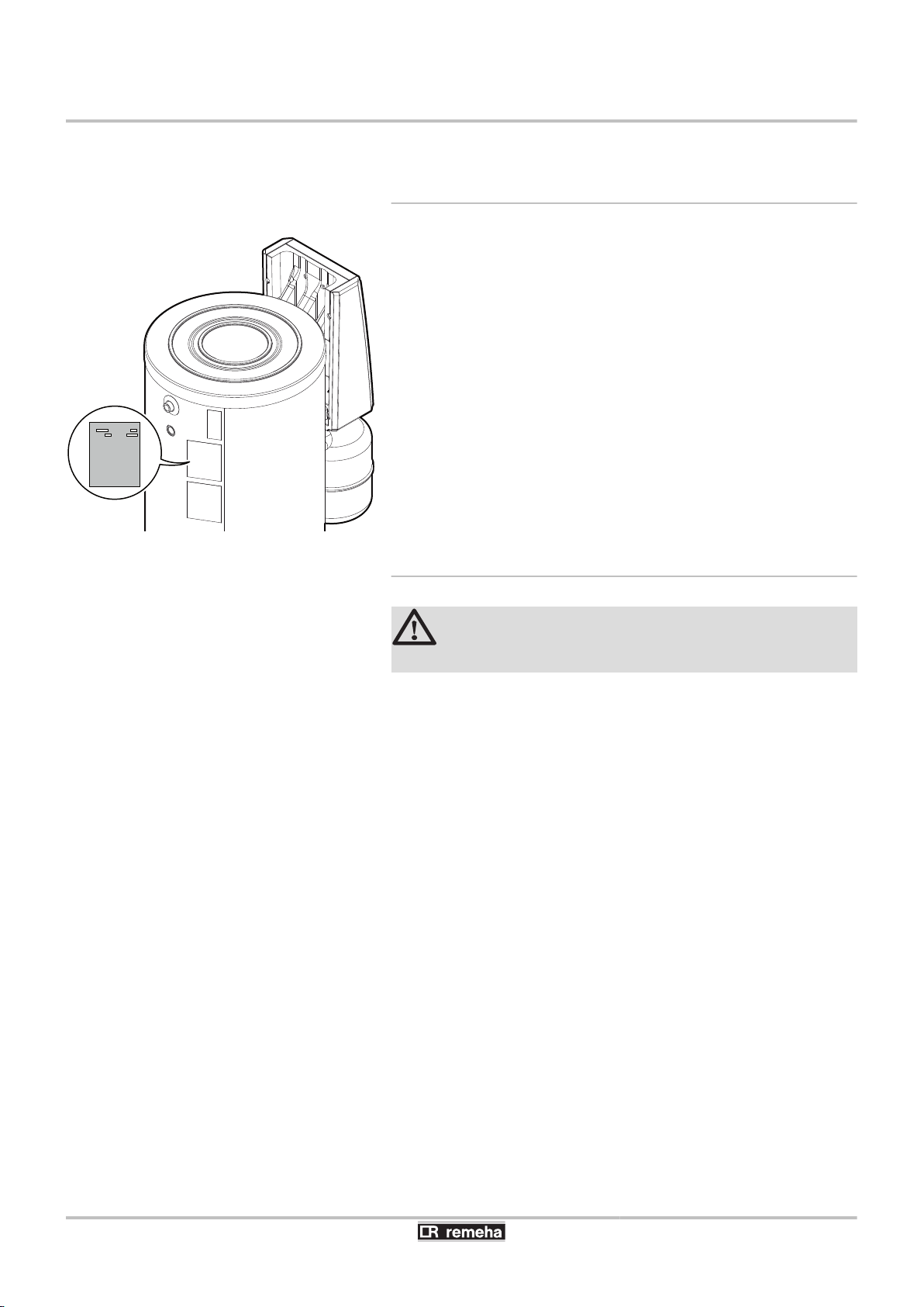
4.3.1. Type plate
The type plate must be accessible at all times.
The type plate identifies the product and provides the following
information:
4 DHW calorifier type
4 Manufacturing date (Year - Week)
4 Serial number.
4.3.2. Positioning of the appliance
CAUTION
Put the appliance in a frost-free location.
4 Place the appliance as close as possible to draw-off points in order
to minimise energy losses through the pipes.
4 Place the appliance on a base frame to facilitate cleaning of the
premises.
4 Install the appliance on a solid, stable structure able to bear its
weight.
20
26/04/2016 - 7607575-05
A
B
C
D
E
F
I
ØG
H
55°
1
3
2
4
5
6
8
7
L000601-B
9
200SE-2S - 300SE-2S 4. Installation
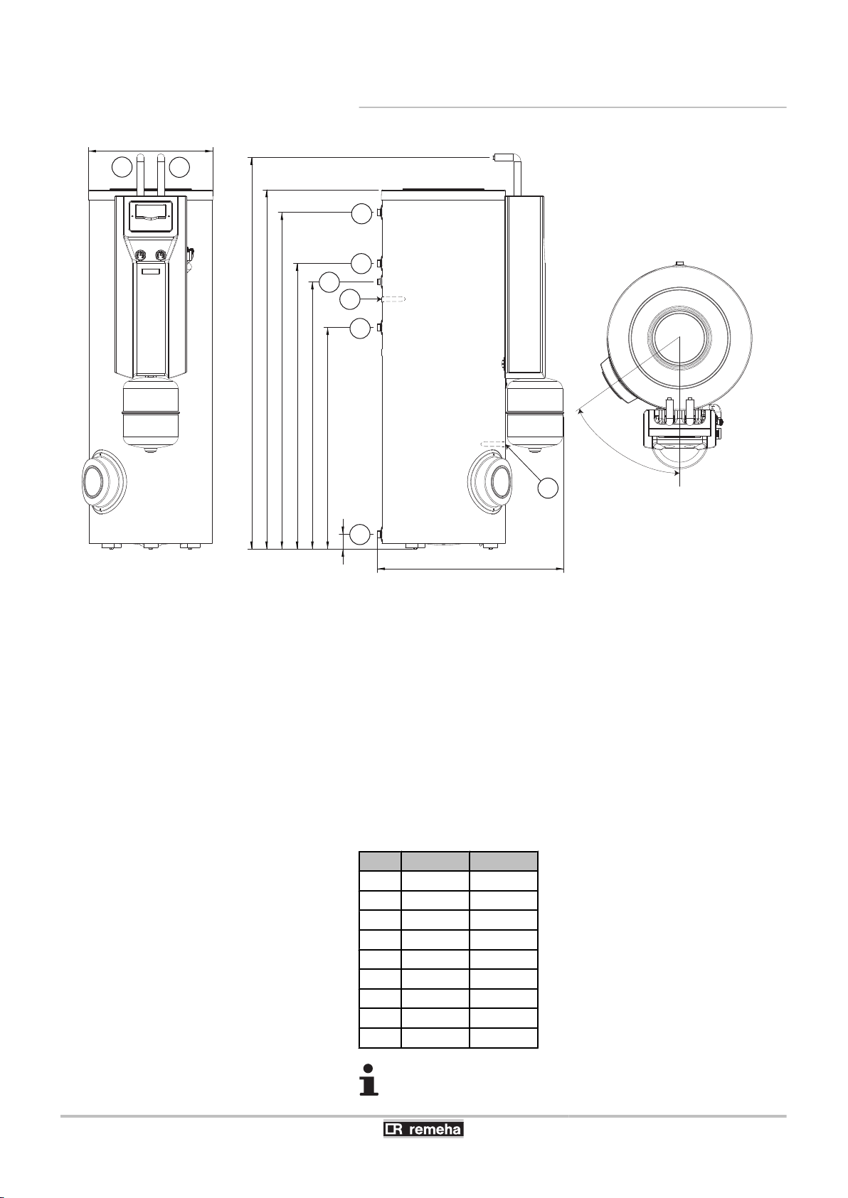
4.3.3. Main dimensions
A
Z
E
R
T
Y
U
I
O
Domestic hot water outlet G1"
Circulation G¾"
Exchanger inlet G1"
Domestic hot water sensor
Exchanger outlet G1"
Domestic cold water inlet + Drain opening G1"
Solar exchanger inlet DN18
Solar exchanger outlet DN18
Position solar sensor
G (Ø)
200SE-2S 300SE-2S
A
B
C
D
E
F
H
I
70.5 71
912 1127
1092 1307
1182 1397
1323.5 1694
1422.5 1796
604 604
892 892
1718 1898
G : Exterior cylindrical threading, sealed by sheet gasket
26/04/2016 - 7607575-05
21
200
200
200
M003153-A
L000382-A
1
2
L000383-A
1
2
3
4. Installation
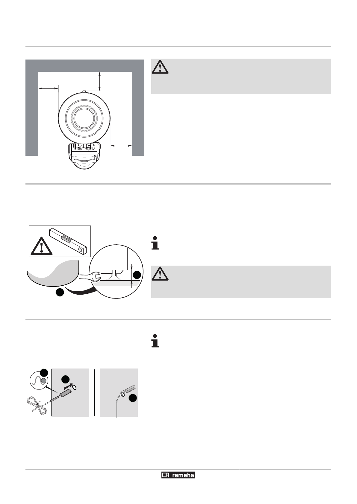
4.4 Positioning the appliance
4.5 Levelling
200SE-2S - 300SE-2S
CAUTION
4 Have 2 people available.
4 Handle the appliance with gloves.
1. Remove the packaging from the DHW calorifier, leaving the
calorifier on the pallet used for transport.
2. Remove the protective packaging.
3. Remove the 3 screws securing the calorifier to the pallet.
4. Lift the DHW calorifier and place it in its final position, respecting
the distances shown on the diagram.
The DHW calorifier is levelled using the 3 feet (delivered in the
instructions pack) to be screwed to the bottom of the DHW calorifier.
1. Mount the 3 adjustable feet under the appliance.
2. Level the appliance using the adjustable feet.
4.6 Installing the temperature sensors
¼See sensor location: "Main dimensions", page 21
1. Insert the sensor into the sensor tube with the help of the sensor
tube separator.
The sensor tube separator is provided in the instructions bag.
2. Check that the sensors are correctly positioned in the sensor
tube.
3. Check the mounting of the sensor tube separator.
Adjustment range: 10 mm.
4
4 Use metal blocks under the feet of the calorifier if
necessary.
CAUTION
Do not place the blocks on the exterior sides of the
domestic hot water calorifier.
The sensors are preinstalled if the calorifier is pre-fitted
with a solar technical station.
22
26/04/2016 - 7607575-05
 Loading...