

REMEHA Quinta Pro series Installation, User And Service Manual
United Kingdom
en
Installation, user and service manual
Wall-hung gas condensing boilers
Quinta Pro
30 – 45 – 65 – 90 – 115

Dear customer,
Thank you for purchasing this appliance.
Please read this manual carefully before using the product and keep it in a safe place for future reference.
In order to ensure continued safe and efficient operation we recommend that the product is regularly maintained. Our Service
and After Sales organization can assist with this.
We hope you will receive many years of satisfactory service.
Remeha B.V.
Postbus 32
7300 AA Apeldoorn
T +31 (0)55 549 6969
I http://nl.remeha.com
E remeha@remeha.com

Contents
1 Safety . . . . . . . . . . . . . . . . . . . . . . . . . . . . . . . . . . . . . . . . . . . . . . . . . . . . . . . . . . . . . . . . . . . . . . . . . . 6
1.1 General safety instructions . . . . . . . . . . . . . . . . . . . . . . . . . . . . . . . . . . . . . . . . . . . . . . . . . . . . . . 6
1.2 Recommendations . . . . . . . . . . . . . . . . . . . . . . . . . . . . . . . . . . . . . . . . . . . . . . . . . . . . . . . . . . . . 7
1.3 Liabilities . . . . . . . . . . . . . . . . . . . . . . . . . . . . . . . . . . . . . . . . . . . . . . . . . . . . . . . . . . . . . . . . . . . . 8
1.3.1 Manufacturer's liability . . . . . . . . . . . . . . . . . . . . . . . . . . . . . . . . . . . . . . . . . . . . . . . . . . . 8
1.3.2 Installer's liability . . . . . . . . . . . . . . . . . . . . . . . . . . . . . . . . . . . . . . . . . . . . . . . . . . . . . . . .9
1.3.3 User's liability . . . . . . . . . . . . . . . . . . . . . . . . . . . . . . . . . . . . . . . . . . . . . . . . . . . . . . . . . . 9
2 About this manual . . . . . . . . . . . . . . . . . . . . . . . . . . . . . . . . . . . . . . . . . . . . . . . . . . . . . . . . . . . . . . . . . . . . . . . . . . . . . . . . . . 10
2.1 Symbols used . . . . . . . . . . . . . . . . . . . . . . . . . . . . . . . . . . . . . . . . . . . . . . . . . . . . . . . . . . . . . . . . . . . . . . . . . . . . . . . . 10
2.1.1 Symbols used in the manual . . . . . . . . . . . . . . . . . . . . . . . . . . . . . . . . . . . . . . . . . . . . . . . . . . . . . . . . . . . . . 10
2.2 Abbreviations . . . . . . . . . . . . . . . . . . . . . . . . . . . . . . . . . . . . . . . . . . . . . . . . . . . . . . . . . . . . . . . . . . . . . . . . . . . . . . . . 10
3 Technical specifications . . . . . . . . . . . . . . . . . . . . . . . . . . . . . . . . . . . . . . . . . . . . . . . . . . . . . . . . . . . . . . . . . . . . . . . . . . . . . 11
3.1 Homologations . . . . . . . . . . . . . . . . . . . . . . . . . . . . . . . . . . . . . . . . . . . . . . . . . . . . . . . . . . . . . . . . . . . . . . . . . . . . . . . 11
3.1.1 Certifications . . . . . . . . . . . . . . . . . . . . . . . . . . . . . . . . . . . . . . . . . . . . . . . . . . . . . . . . . . . . . . . . . . . . . . . . . 11
3.1.2 Unit categories . . . . . . . . . . . . . . . . . . . . . . . . . . . . . . . . . . . . . . . . . . . . . . . . . . . . . . . . . . . . . . . . . . . . . . . .11
3.1.3 Directives . . . . . . . . . . . . . . . . . . . . . . . . . . . . . . . . . . . . . . . . . . . . . . . . . . . . . . . . . . . . . . . . . . . . . . . . . . . .11
3.1.4 Factory test . . . . . . . . . . . . . . . . . . . . . . . . . . . . . . . . . . . . . . . . . . . . . . . . . . . . . . . . . . . . . . . . . . . . . . . . . . 11
3.2 Technical data . . . . . . . . . . . . . . . . . . . . . . . . . . . . . . . . . . . . . . . . . . . . . . . . . . . . . . . . . . . . . . . . . . . . . . . . . . . . . . . .11
3.3 Dimensions and connections . . . . . . . . . . . . . . . . . . . . . . . . . . . . . . . . . . . . . . . . . . . . . . . . . . . . . . . . . . . . . . . . . . . . 14
3.4 Electrical diagram . . . . . . . . . . . . . . . . . . . . . . . . . . . . . . . . . . . . . . . . . . . . . . . . . . . . . . . . . . . . . . . . . . . . . . . . . . . . . 15
4 Description of the product . . . . . . . . . . . . . . . . . . . . . . . . . . . . . . . . . . . . . . . . . . . . . . . . . . . . . . . . . . . . . . . . . . . . . . . . . . . . 16
4.1 General description . . . . . . . . . . . . . . . . . . . . . . . . . . . . . . . . . . . . . . . . . . . . . . . . . . . . . . . . . . . . . . . . . . . . . . . . . . . .16
4.2 Operating principle . . . . . . . . . . . . . . . . . . . . . . . . . . . . . . . . . . . . . . . . . . . . . . . . . . . . . . . . . . . . . . . . . . . . . . . . . . . . 16
4.2.1 Circulating pump . . . . . . . . . . . . . . . . . . . . . . . . . . . . . . . . . . . . . . . . . . . . . . . . . . . . . . . . . . . . . . . . . . . . . . 16
4.2.2 Cascade system . . . . . . . . . . . . . . . . . . . . . . . . . . . . . . . . . . . . . . . . . . . . . . . . . . . . . . . . . . . . . . . . . . . . . . 16
4.2.3 Water flow . . . . . . . . . . . . . . . . . . . . . . . . . . . . . . . . . . . . . . . . . . . . . . . . . . . . . . . . . . . . . . . . . . . . . . . . . . . 16
4.2.4 Calorifier connection . . . . . . . . . . . . . . . . . . . . . . . . . . . . . . . . . . . . . . . . . . . . . . . . . . . . . . . . . . . . . . . . . . . 16
4.3 Main components . . . . . . . . . . . . . . . . . . . . . . . . . . . . . . . . . . . . . . . . . . . . . . . . . . . . . . . . . . . . . . . . . . . . . . . . . . . . . 17
4.4 Control panel description . . . . . . . . . . . . . . . . . . . . . . . . . . . . . . . . . . . . . . . . . . . . . . . . . . . . . . . . . . . . . . . . . . . . . . . 17
4.4.1 What each key means . . . . . . . . . . . . . . . . . . . . . . . . . . . . . . . . . . . . . . . . . . . . . . . . . . . . . . . . . . . . . . . . . . 17
4.4.2 Meaning of the symbols on the display . . . . . . . . . . . . . . . . . . . . . . . . . . . . . . . . . . . . . . . . . . . . . . . . . . . . . 17
4.5 Standard delivery . . . . . . . . . . . . . . . . . . . . . . . . . . . . . . . . . . . . . . . . . . . . . . . . . . . . . . . . . . . . . . . . . . . . . . . . . . . . . 18
4.6 Accessories and options . . . . . . . . . . . . . . . . . . . . . . . . . . . . . . . . . . . . . . . . . . . . . . . . . . . . . . . . . . . . . . . . . . . . . . . .18
5 Before installation . . . . . . . . . . . . . . . . . . . . . . . . . . . . . . . . . . . . . . . . . . . . . . . . . . . . . . . . . . . . . . . . . . . . . . . . . . . . . . . . . . 19
5.1 Installation regulations . . . . . . . . . . . . . . . . . . . . . . . . . . . . . . . . . . . . . . . . . . . . . . . . . . . . . . . . . . . . . . . . . . . . . . . . . 19
5.2 Choice of the location . . . . . . . . . . . . . . . . . . . . . . . . . . . . . . . . . . . . . . . . . . . . . . . . . . . . . . . . . . . . . . . . . . . . . . . . . . 19
5.2.1 Type plate . . . . . . . . . . . . . . . . . . . . . . . . . . . . . . . . . . . . . . . . . . . . . . . . . . . . . . . . . . . . . . . . . . . . . . . . . . . 19
5.2.2 Boiler position . . . . . . . . . . . . . . . . . . . . . . . . . . . . . . . . . . . . . . . . . . . . . . . . . . . . . . . . . . . . . . . . . . . . . . . . 20
5.3 Ventilation . . . . . . . . . . . . . . . . . . . . . . . . . . . . . . . . . . . . . . . . . . . . . . . . . . . . . . . . . . . . . . . . . . . . . . . . . . . . . . . . . . . 20
6 Installation . . . . . . . . . . . . . . . . . . . . . . . . . . . . . . . . . . . . . . . . . . . . . . . . . . . . . . . . . . . . . . . . . . . . . . . . . . . . . . . . . . . . . . . . 21
6.1 General . . . . . . . . . . . . . . . . . . . . . . . . . . . . . . . . . . . . . . . . . . . . . . . . . . . . . . . . . . . . . . . . . . . . . . . . . . . . . . . . . . . . . 21
6.2 Preparation . . . . . . . . . . . . . . . . . . . . . . . . . . . . . . . . . . . . . . . . . . . . . . . . . . . . . . . . . . . . . . . . . . . . . . . . . . . . . . . . . . 21
6.2.1 Positioning the boiler . . . . . . . . . . . . . . . . . . . . . . . . . . . . . . . . . . . . . . . . . . . . . . . . . . . . . . . . . . . . . . . . . . . 21
6.3 Water connections . . . . . . . . . . . . . . . . . . . . . . . . . . . . . . . . . . . . . . . . . . . . . . . . . . . . . . . . . . . . . . . . . . . . . . . . . . . . 21
6.3.1 Rinsing the system . . . . . . . . . . . . . . . . . . . . . . . . . . . . . . . . . . . . . . . . . . . . . . . . . . . . . . . . . . . . . . . . . . . . 21
6.3.2 Connecting the heating circuit . . . . . . . . . . . . . . . . . . . . . . . . . . . . . . . . . . . . . . . . . . . . . . . . . . . . . . . . . . . . 22
6.3.3 Connecting the expansion vessel . . . . . . . . . . . . . . . . . . . . . . . . . . . . . . . . . . . . . . . . . . . . . . . . . . . . . . . . . 22
6.3.4 Connecting the condensate discharge pipe . . . . . . . . . . . . . . . . . . . . . . . . . . . . . . . . . . . . . . . . . . . . . . . . . .23
6.4 Gas connection . . . . . . . . . . . . . . . . . . . . . . . . . . . . . . . . . . . . . . . . . . . . . . . . . . . . . . . . . . . . . . . . . . . . . . . . . . . . . . .23
6.5 Air supply/flue gas connections . . . . . . . . . . . . . . . . . . . . . . . . . . . . . . . . . . . . . . . . . . . . . . . . . . . . . . . . . . . . . . . . . . 23
6.5.1 Classification . . . . . . . . . . . . . . . . . . . . . . . . . . . . . . . . . . . . . . . . . . . . . . . . . . . . . . . . . . . . . . . . . . . . . . . . . 23
6.5.2 Outlets . . . . . . . . . . . . . . . . . . . . . . . . . . . . . . . . . . . . . . . . . . . . . . . . . . . . . . . . . . . . . . . . . . . . . . . . . . . . . . 25
6.5.3 Length of the air and flue gas pipes . . . . . . . . . . . . . . . . . . . . . . . . . . . . . . . . . . . . . . . . . . . . . . . . . . . . . . . .25
6.5.4 Additional guidelines . . . . . . . . . . . . . . . . . . . . . . . . . . . . . . . . . . . . . . . . . . . . . . . . . . . . . . . . . . . . . . . . . . . 27
6.5.5 Flue gas outlet and air supply connection . . . . . . . . . . . . . . . . . . . . . . . . . . . . . . . . . . . . . . . . . . . . . . . . . . . 27
6.6 Electrical connections . . . . . . . . . . . . . . . . . . . . . . . . . . . . . . . . . . . . . . . . . . . . . . . . . . . . . . . . . . . . . . . . . . . . . . . . . . 27
6.6.1 Control unit . . . . . . . . . . . . . . . . . . . . . . . . . . . . . . . . . . . . . . . . . . . . . . . . . . . . . . . . . . . . . . . . . . . . . . . . . . 27
Contents
123157 - v.06 - 24022015 3

6.6.2 Recommendations . . . . . . . . . . . . . . . . . . . . . . . . . . . . . . . . . . . . . . . . . . . . . . . . . . . . . . . . . . . . . . . . . . . . .28
6.6.3 Access to the connectors . . . . . . . . . . . . . . . . . . . . . . . . . . . . . . . . . . . . . . . . . . . . . . . . . . . . . . . . . . . . . . . .29
6.6.4 Connection options for the standard PCB . . . . . . . . . . . . . . . . . . . . . . . . . . . . . . . . . . . . . . . . . . . . . . . . . . . 30
6.6.5 PCBs . . . . . . . . . . . . . . . . . . . . . . . . . . . . . . . . . . . . . . . . . . . . . . . . . . . . . . . . . . . . . . . . . . . . . . . . . . . . . . . 35
6.7 Filling the system . . . . . . . . . . . . . . . . . . . . . . . . . . . . . . . . . . . . . . . . . . . . . . . . . . . . . . . . . . . . . . . . . . . . . . . . . . . . . 38
6.7.1 Water treatment . . . . . . . . . . . . . . . . . . . . . . . . . . . . . . . . . . . . . . . . . . . . . . . . . . . . . . . . . . . . . . . . . . . . . . .38
6.7.2 Filling the siphon . . . . . . . . . . . . . . . . . . . . . . . . . . . . . . . . . . . . . . . . . . . . . . . . . . . . . . . . . . . . . . . . . . . . . . 39
6.7.3 Filling the system . . . . . . . . . . . . . . . . . . . . . . . . . . . . . . . . . . . . . . . . . . . . . . . . . . . . . . . . . . . . . . . . . . . . . .39
7 Commissioning . . . . . . . . . . . . . . . . . . . . . . . . . . . . . . . . . . . . . . . . . . . . . . . . . . . . . . . . . . . . . . . . . . . . . . . . . . . . . . . . . . . . 40
7.1 General . . . . . . . . . . . . . . . . . . . . . . . . . . . . . . . . . . . . . . . . . . . . . . . . . . . . . . . . . . . . . . . . . . . . . . . . . . . . . . . . . . . . . 40
7.2 Gas circuit . . . . . . . . . . . . . . . . . . . . . . . . . . . . . . . . . . . . . . . . . . . . . . . . . . . . . . . . . . . . . . . . . . . . . . . . . . . . . . . . . . .40
7.3 Hydraulic circuit . . . . . . . . . . . . . . . . . . . . . . . . . . . . . . . . . . . . . . . . . . . . . . . . . . . . . . . . . . . . . . . . . . . . . . . . . . . . . . .40
7.4 Electrical connections . . . . . . . . . . . . . . . . . . . . . . . . . . . . . . . . . . . . . . . . . . . . . . . . . . . . . . . . . . . . . . . . . . . . . . . . . . 40
7.5 Commissioning procedure . . . . . . . . . . . . . . . . . . . . . . . . . . . . . . . . . . . . . . . . . . . . . . . . . . . . . . . . . . . . . . . . . . . . . . 40
7.6 Gas settings . . . . . . . . . . . . . . . . . . . . . . . . . . . . . . . . . . . . . . . . . . . . . . . . . . . . . . . . . . . . . . . . . . . . . . . . . . . . . . . . . 41
7.6.1 Adaptation to a different gas type . . . . . . . . . . . . . . . . . . . . . . . . . . . . . . . . . . . . . . . . . . . . . . . . . . . . . . . . . 41
7.6.2 Checking and setting the gas/air ratio . . . . . . . . . . . . . . . . . . . . . . . . . . . . . . . . . . . . . . . . . . . . . . . . . . . . . . 42
7.7 Final instructions . . . . . . . . . . . . . . . . . . . . . . . . . . . . . . . . . . . . . . . . . . . . . . . . . . . . . . . . . . . . . . . . . . . . . . . . . . . . . .44
8 Operation . . . . . . . . . . . . . . . . . . . . . . . . . . . . . . . . . . . . . . . . . . . . . . . . . . . . . . . . . . . . . . . . . . . . . . . . . . . . . . . . . . . . . . . . .45
8.1 Use of the control panel . . . . . . . . . . . . . . . . . . . . . . . . . . . . . . . . . . . . . . . . . . . . . . . . . . . . . . . . . . . . . . . . . . . . . . . . 45
8.2 Shutdown . . . . . . . . . . . . . . . . . . . . . . . . . . . . . . . . . . . . . . . . . . . . . . . . . . . . . . . . . . . . . . . . . . . . . . . . . . . . . . . . . . . 45
8.3 Frost protection . . . . . . . . . . . . . . . . . . . . . . . . . . . . . . . . . . . . . . . . . . . . . . . . . . . . . . . . . . . . . . . . . . . . . . . . . . . . . . .45
9 Settings . . . . . . . . . . . . . . . . . . . . . . . . . . . . . . . . . . . . . . . . . . . . . . . . . . . . . . . . . . . . . . . . . . . . . . . . . . . . . . . . . . . . . . . . . . 46
9.1 Parameter descriptions . . . . . . . . . . . . . . . . . . . . . . . . . . . . . . . . . . . . . . . . . . . . . . . . . . . . . . . . . . . . . . . . . . . . . . . . .46
9.2 Changing the parameters . . . . . . . . . . . . . . . . . . . . . . . . . . . . . . . . . . . . . . . . . . . . . . . . . . . . . . . . . . . . . . . . . . . . . . . 48
9.2.1 Changing the user-level parameters . . . . . . . . . . . . . . . . . . . . . . . . . . . . . . . . . . . . . . . . . . . . . . . . . . . . . . . 48
9.2.2 Changing the parameters at installer level . . . . . . . . . . . . . . . . . . . . . . . . . . . . . . . . . . . . . . . . . . . . . . . . . . 49
9.2.3 Setting the maximum load for CH operation . . . . . . . . . . . . . . . . . . . . . . . . . . . . . . . . . . . . . . . . . . . . . . . . . 49
9.2.4 Return to the factory settings . . . . . . . . . . . . . . . . . . . . . . . . . . . . . . . . . . . . . . . . . . . . . . . . . . . . . . . . . . . . .51
9.2.5 Carrying out an auto-detect . . . . . . . . . . . . . . . . . . . . . . . . . . . . . . . . . . . . . . . . . . . . . . . . . . . . . . . . . . . . . . 51
9.2.6 Setting the manual mode . . . . . . . . . . . . . . . . . . . . . . . . . . . . . . . . . . . . . . . . . . . . . . . . . . . . . . . . . . . . . . . .52
9.3 Displaying the measured values . . . . . . . . . . . . . . . . . . . . . . . . . . . . . . . . . . . . . . . . . . . . . . . . . . . . . . . . . . . . . . . . . .52
9.3.1 Reading the various current values . . . . . . . . . . . . . . . . . . . . . . . . . . . . . . . . . . . . . . . . . . . . . . . . . . . . . . . . 52
9.3.2 Reading out the hour counter and percentage of successful starts . . . . . . . . . . . . . . . . . . . . . . . . . . . . . . . .53
9.3.3 Status and sub-status . . . . . . . . . . . . . . . . . . . . . . . . . . . . . . . . . . . . . . . . . . . . . . . . . . . . . . . . . . . . . . . . . . 54
10 Maintenance . . . . . . . . . . . . . . . . . . . . . . . . . . . . . . . . . . . . . . . . . . . . . . . . . . . . . . . . . . . . . . . . . . . . . . . . . . . . . . . . . . . . . . 56
10.1 General . . . . . . . . . . . . . . . . . . . . . . . . . . . . . . . . . . . . . . . . . . . . . . . . . . . . . . . . . . . . . . . . . . . . . . . . . . . . . . . . . . . . . 56
10.2 Service message . . . . . . . . . . . . . . . . . . . . . . . . . . . . . . . . . . . . . . . . . . . . . . . . . . . . . . . . . . . . . . . . . . . . . . . . . . . . . .56
10.2.1 Resetting the service messages . . . . . . . . . . . . . . . . . . . . . . . . . . . . . . . . . . . . . . . . . . . . . . . . . . . . . . . . . . 56
10.2.2 Starting a new service interval . . . . . . . . . . . . . . . . . . . . . . . . . . . . . . . . . . . . . . . . . . . . . . . . . . . . . . . . . . . .57
10.3 Standard inspection and maintenance operations . . . . . . . . . . . . . . . . . . . . . . . . . . . . . . . . . . . . . . . . . . . . . . . . . . . . 57
10.3.1 Checking the water pressure . . . . . . . . . . . . . . . . . . . . . . . . . . . . . . . . . . . . . . . . . . . . . . . . . . . . . . . . . . . . .57
10.3.2 Checking the ionisation current . . . . . . . . . . . . . . . . . . . . . . . . . . . . . . . . . . . . . . . . . . . . . . . . . . . . . . . . . . . 58
10.3.3 Checking the flue gas outlet/air supply connections . . . . . . . . . . . . . . . . . . . . . . . . . . . . . . . . . . . . . . . . . . . 58
10.3.4 Checking the combustion . . . . . . . . . . . . . . . . . . . . . . . . . . . . . . . . . . . . . . . . . . . . . . . . . . . . . . . . . . . . . . . 58
10.3.5 Checking the automatic air vent . . . . . . . . . . . . . . . . . . . . . . . . . . . . . . . . . . . . . . . . . . . . . . . . . . . . . . . . . . 59
10.3.6 Cleaning the siphon . . . . . . . . . . . . . . . . . . . . . . . . . . . . . . . . . . . . . . . . . . . . . . . . . . . . . . . . . . . . . . . . . . . .60
10.3.7 Checking the burner and cleaning the heat exchanger . . . . . . . . . . . . . . . . . . . . . . . . . . . . . . . . . . . . . . . . . 61
10.4 Specific maintenance work . . . . . . . . . . . . . . . . . . . . . . . . . . . . . . . . . . . . . . . . . . . . . . . . . . . . . . . . . . . . . . . . . . . . . . 62
10.4.1 Replacing the ionisation/ignition electrode . . . . . . . . . . . . . . . . . . . . . . . . . . . . . . . . . . . . . . . . . . . . . . . . . . 62
10.4.2 Checking the non-return valve . . . . . . . . . . . . . . . . . . . . . . . . . . . . . . . . . . . . . . . . . . . . . . . . . . . . . . . . . . . .63
10.4.3 Reassembling the boiler . . . . . . . . . . . . . . . . . . . . . . . . . . . . . . . . . . . . . . . . . . . . . . . . . . . . . . . . . . . . . . . . 63
11 Troubleshooting . . . . . . . . . . . . . . . . . . . . . . . . . . . . . . . . . . . . . . . . . . . . . . . . . . . . . . . . . . . . . . . . . . . . . . . . . . . . . . . . . . . .64
11.1 Error codes . . . . . . . . . . . . . . . . . . . . . . . . . . . . . . . . . . . . . . . . . . . . . . . . . . . . . . . . . . . . . . . . . . . . . . . . . . . . . . . . . . 64
11.1.1 Blocking . . . . . . . . . . . . . . . . . . . . . . . . . . . . . . . . . . . . . . . . . . . . . . . . . . . . . . . . . . . . . . . . . . . . . . . . . . . . . 64
11.1.2 Lock out . . . . . . . . . . . . . . . . . . . . . . . . . . . . . . . . . . . . . . . . . . . . . . . . . . . . . . . . . . . . . . . . . . . . . . . . . . . . . 65
11.2 Error memory . . . . . . . . . . . . . . . . . . . . . . . . . . . . . . . . . . . . . . . . . . . . . . . . . . . . . . . . . . . . . . . . . . . . . . . . . . . . . . . . 68
11.2.1 Reading out the error memory . . . . . . . . . . . . . . . . . . . . . . . . . . . . . . . . . . . . . . . . . . . . . . . . . . . . . . . . . . . .69
11.2.2 Clearing error memory . . . . . . . . . . . . . . . . . . . . . . . . . . . . . . . . . . . . . . . . . . . . . . . . . . . . . . . . . . . . . . . . . .70
12 Disposal . . . . . . . . . . . . . . . . . . . . . . . . . . . . . . . . . . . . . . . . . . . . . . . . . . . . . . . . . . . . . . . . . . . . . . . . . . . . . . . . . . . . . . . . . .71
Contents
4 123157 - v.06 - 24022015

12.1 Removal/recycling . . . . . . . . . . . . . . . . . . . . . . . . . . . . . . . . . . . . . . . . . . . . . . . . . . . . . . . . . . . . . . . . . . . . . . . . . . . . .71
13 Spare parts . . . . . . . . . . . . . . . . . . . . . . . . . . . . . . . . . . . . . . . . . . . . . . . . . . . . . . . . . . . . . . . . . . . . . . . . . . . . . . . . . . . . . . . 72
13.1 General . . . . . . . . . . . . . . . . . . . . . . . . . . . . . . . . . . . . . . . . . . . . . . . . . . . . . . . . . . . . . . . . . . . . . . . . . . . . . . . . . . . . . 72
13.2 Parts . . . . . . . . . . . . . . . . . . . . . . . . . . . . . . . . . . . . . . . . . . . . . . . . . . . . . . . . . . . . . . . . . . . . . . . . . . . . . . . . . . . . . . . 73
14 Appendix . . . . . . . . . . . . . . . . . . . . . . . . . . . . . . . . . . . . . . . . . . . . . . . . . . . . . . . . . . . . . . . . . . . . . . . . . . . . . . . . . . . . . . . . . 77
14.1 ErP information . . . . . . . . . . . . . . . . . . . . . . . . . . . . . . . . . . . . . . . . . . . . . . . . . . . . . . . . . . . . . . . . . . . . . . . . . . . . . . . 77
14.1.1 Product card . . . . . . . . . . . . . . . . . . . . . . . . . . . . . . . . . . . . . . . . . . . . . . . . . . . . . . . . . . . . . . . . . . . . . . . . . 77
14.1.2 Package sheet . . . . . . . . . . . . . . . . . . . . . . . . . . . . . . . . . . . . . . . . . . . . . . . . . . . . . . . . . . . . . . . . . . . . . . . .78
14.2 EC declaration of conformity . . . . . . . . . . . . . . . . . . . . . . . . . . . . . . . . . . . . . . . . . . . . . . . . . . . . . . . . . . . . . . . . . . . . .79
14.3 Optional electrical connections . . . . . . . . . . . . . . . . . . . . . . . . . . . . . . . . . . . . . . . . . . . . . . . . . . . . . . . . . . . . . . . . . . . 79
14.3.1 Housing for PCBs . . . . . . . . . . . . . . . . . . . . . . . . . . . . . . . . . . . . . . . . . . . . . . . . . . . . . . . . . . . . . . . . . . . . . 79
14.3.2 Connection options for the PCB (SCU-S03) . . . . . . . . . . . . . . . . . . . . . . . . . . . . . . . . . . . . . . . . . . . . . . . . . 80
14.3.3 Connection options for the PCB (SCU-X02) . . . . . . . . . . . . . . . . . . . . . . . . . . . . . . . . . . . . . . . . . . . . . . . . . 80
14.3.4 Connection options for the PCB (SCU-X03) . . . . . . . . . . . . . . . . . . . . . . . . . . . . . . . . . . . . . . . . . . . . . . . . . 81
14.3.5 Connection options for the PCB (c-Mix) . . . . . . . . . . . . . . . . . . . . . . . . . . . . . . . . . . . . . . . . . . . . . . . . . . . . 82
Contents
123157 - v.06 - 24022015 5
1 Safety
1.1 General safety instructions
For the installer:
Danger
If you smell gas:
1. Do not use naked flames, do not smoke and do
not operate electrical contacts or switches (door
bell, lighting, motor, lift etc).
2. Shut off the gas supply.
3. Open the windows.
4. Trace possible leaks and seal them off immediate
ly.
5. If the leak is upstream of the gas meter, notify the
gas company.
Danger
If you smell flue gases:
1. Switch the boiler off.
2. Open the windows.
3. Trace possible leaks and seal them off immediate
ly.
Caution
After maintenance or repair work, check the entire
heating installation to ensure that there are no leaks.
For the end user:
Danger
If you smell gas:
1. Do not use naked flames, do not smoke and do
not operate electrical contacts or switches (door
bell, lighting, motor, lift etc).
2. Shut off the gas supply.
3. Open the windows.
4. Report any leaks immediately.
5. Evacuate the property.
6. Contact a qualified installer.
Danger
If you smell flue gases:
1. Switch the boiler off.
2. Open the windows.
3. Report any leaks immediately.
4. Evacuate the property.
5. Contact a qualified installer.
Warning
Do not touch the flue gas pipes. Depending on the
boiler settings, the temperature of the flue gas pipes
can rise to over 60°C.
1 Safety
6 123157 - v.06 - 24022015
Warning
Do not touch radiators for long periods. Depending on
the boiler settings, the temperature of the radiators
can rise to over 60°C.
Caution
Ensure that the boiler is regularly serviced. Contact a
qualified installer or arrange a maintenance contract
for the servicing of the boiler.
Caution
Only genuine spare parts may be used.
Note
Regularly check for the presence of water and pres
sure in the heating installation.
1.2 Recommendations
Danger
This appliance must not be used by people (and chil
dren) with a physical, sensory or mental disability, or
by people with a lack of technical experience, unless
they are supervised by someone who can assure their
safety, or they have been instructed in the correct use
of the appliance. Do not allow children to play with the
appliance.
Warning
Installation and maintenance of the boiler must be car
ried out by a qualified installer in accordance with lo
cal and national regulations.
Warning
Removal and disposal of the boiler must be carried
out by a qualified installer in accordance with local
and national regulations.
Warning
If the mains lead is damaged, it must be replaced by
the original manufacturer, the manufacturer's dealer
or another suitably skilled person to prevent hazard
ous situations from arising.
Warning
Always disconnect the mains supply and close the
main gas tap when working on the boiler.
Warning
Check the entire system for leaks after maintenance
and servicing work.
1 Safety
123157 - v.06 - 24022015 7
Caution
Make sure the boiler can be reached at all times.
The boiler must be installed in a frost-free area.
In the case of a fixed connection to the power cord,
you must always install a main bipolar switch with an
opening gap of at least 3 mm (EN 60335-1).
Drain the boiler and central heating system if you
are not going to use your home for a long time and
there is a chance of frost.
The frost protection does not work if the boiler is out
of operation.
The boiler protection only protects the boiler, not the
system.
Check the water pressure in the system regularly. If
the water pressure is lower than 0.8 bar, the system
must be topped up (recommended water pressure
between 1.5 and 2 bar).
Note
Keep this document near to the boiler.
Note
Casing panels may only be removed for maintenance
and servicing purposes. Refit all panels when mainte
nance work and servicing are complete.
Note
Instruction and warning labels must never be removed
or covered and must be clearly legible throughout the
entire service life of the boiler. Replace damaged or il
legible instruction and warning labels immediately.
Note
Modifications to the boiler require the written approval
of Remeha.
1.3 Liabilities
1.3.1 Manufacturer's liability
Our products are manufactured in compliance with the re
quirements of the various Directives applicable. They are
therefore delivered with the marking and any documents
necessary. In the interests of the quality of our products, we
strive constantly to improve them. We therefore reserve the
right to modify the specifications given in this document.
Our liability as manufacturer may not be invoked in the fol
lowing cases:
Failure to abide by the instructions on installing the appli
ance.
Failure to abide by the instructions on using the appliance.
Faulty or insufficient maintenance of the appliance.
1 Safety
8 123157 - v.06 - 24022015

1.3.2 Installer's liability
The installer is responsible for the installation and initial com
missioning of the appliance. The installer must abide by the
following instructions:
Read and follow the instructions given in the manuals pro
vided with the appliance.
Install the appliance in compliance with prevailing legisla
tion and standards.
Carry out initial commissioning and any checks necessary.
Explain the installation to the user.
If maintenance is necessary, warn the user of the obliga
tion to check the appliance and keep it in good working or
der.
Give all the instruction manuals to the user.
1.3.3 User's liability
To guarantee optimum running of the installation, you must
abide by the following instructions:
Read and follow the instructions given in the manuals pro
vided with the appliance.
Call on a qualified professional to carry out installation and
initial commissioning.
Get your installer to explain your installation to you.
Have the required checks and services done by a qualified
professional.
Keep the instruction manuals in good condition close to the
appliance.
1 Safety
123157 - v.06 - 24022015 9
2 About this manual
2.1 Symbols used
2.1.1 Symbols used in the manual
This manual uses various danger levels to draw attention to special in
structions. We do this to improve user safety, to prevent problems and to
guarantee correct operation of the appliance.
Danger
Risk of dangerous situations resulting in serious personal injury.
Danger of electric shock
Risk of electric shock.
Warning
Risk of dangerous situations resulting in minor personal injury.
Caution
Risk of material damage.
Note
Please note: important information.
See
Reference to other manuals or pages in this manual.
2.2 Abbreviations
DHW Domestic hot water
PCU PCB for managing burner operation
PWM Pulse wide modulation
SCU Control panel PCB
SU Safety PCB
2 About this manual
10 123157 - v.06 - 24022015
3 Technical specifications
3.1 Homologations
3.1.1 Certifications
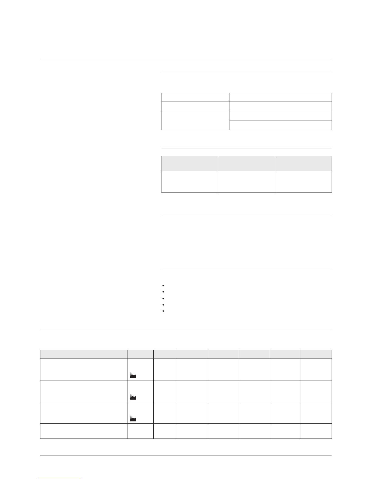
Tab.1 Certifications
CE identification number PIN 0063CL3333
NOx class 5 (EN 15502–1)
Type of connection B23, B
23P
, B
33
C13, C33, C43, C53, C63, C83, C
93
3.1.2 Unit categories
Category Gas type Connection pressure
(mbar)
II
2H3B/P
G20 (H gas)
G30/G31 (butane/
propane)
20
30-50
3.1.3 Directives
In addition to the legal requirements and guidelines, the supplementary
guidelines in this manual must also be followed.
Supplements or subsequent regulations and guidelines that are valid at
the time of installation shall apply to all regulations and guidelines speci
fied in this manual.
3.1.4 Factory test
Before leaving the factory, each boiler is optimally set and tested for:
Electrical safety.
Adjustment of (O2/CO2).
Water tightness.
Gas tightness.
Parameter setting.
3.2 Technical data
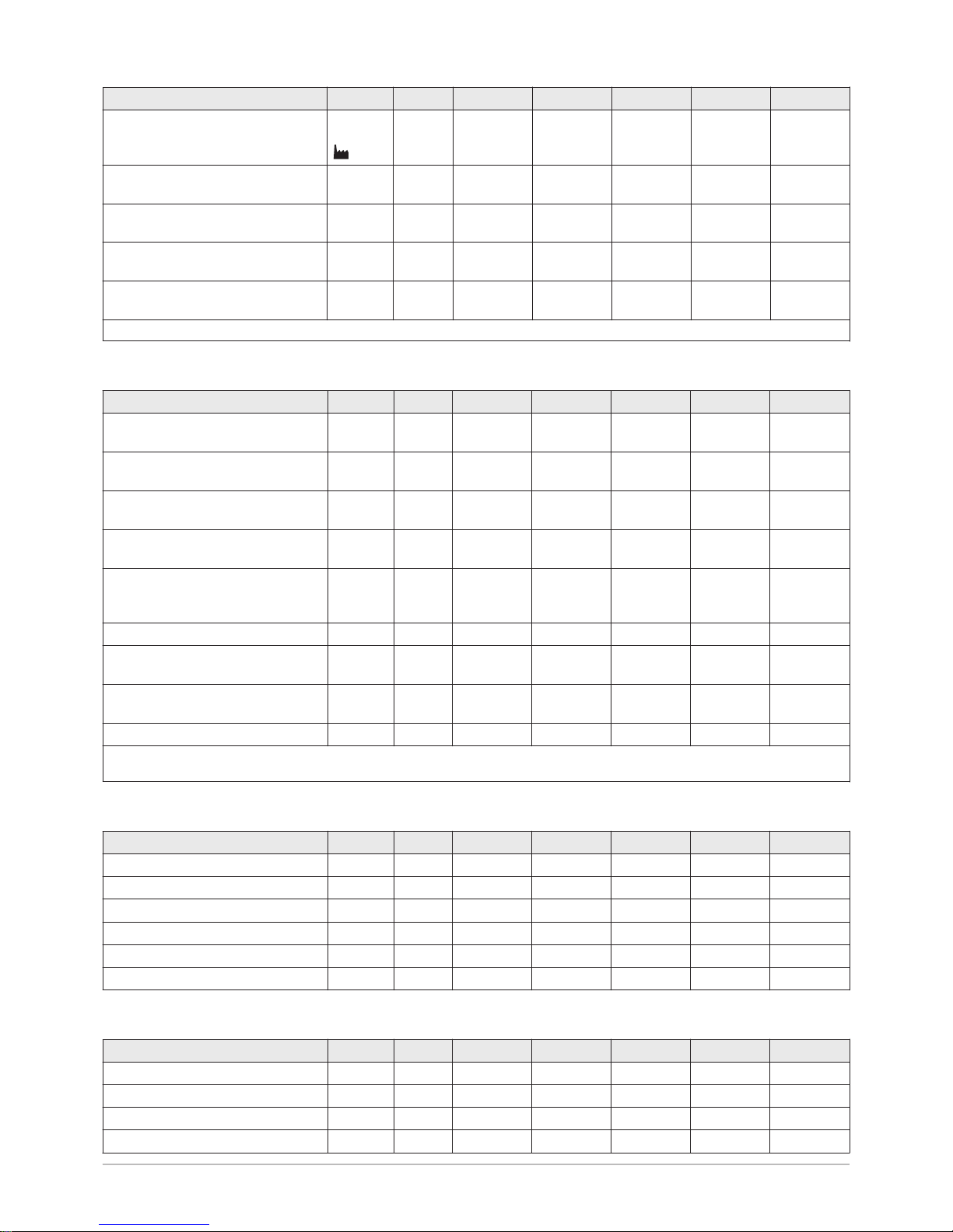
Tab.2 General
Quinta Pro 30 45 65 90 115
Nominal output (Pn)
Central heating operation (80°C/
60°C)
min.–
max.
(1)
kW 8.0–29.3
29.3
8.0–40.0
40.0
12.0–61.0
61.0
14.1–84.2
84.2
20.5–107.0
107.0
Nominal output (Pn)
Central heating operation (50°C/
30°C)
min.–
max.
(1)
kW 8.9–31.4
31.4
8.9–43.0
43.0
13.3–65.0
65.0
15.8–89.5
89.5
22.7–114.0
114.0
Nominal input (Qn)
Central heating operation (Hi)
min.–
max.
(1)
kW 8.2–30.0
30.0
8.2–41.2
41.2
12.2–62.0
62.0
14.6–86.0
86.0
19.6–110.2
110.2
Nominal input (Qn)
CH operation (Hi) G31 (propane)
min kW 8.8 8.8 12.2 22.1 21.2
3 Technical specifications
123157 - v.06 - 24022015 11
Quinta Pro 30 45 65 90 115
Nominal input (Qn)
Central heating operation (Hs)
min.–
max.
(1)
kW 9.1–33.3
33.3
9.1–45.7
45.7
13.6–68.8
68.8
16.2–95.5
95.5
21.9–122.4
122.4
Full load central heating efficiency
(Hi) (80°C/60°C)
% 97.5 97.2 98.3 97.9 97.1
Full load central heating efficiency
(Hi) (50°C/30°C)
% 102.9 102.9 104.6 104.1 102.5
Low load central heating efficiency
(Hi) (return temperature 60°C)
% 97.5 97.5 98.3 96.6 96.5
Partial load CH efficiency (return
temperature 30°C)
% 108.5 108.4 108.9 108.1 108.0
(1) Factory setting
Tab.3 Gas and flue gas data
Quinta Pro 30 45 65 90 115
Gas inlet pressure G20 (H gas) min.–
max.
mbar 17–25 17–25 17–25 17–25 17–25
Gas inlet pressure G31 (propane) min.–
max.
mbar 37–50 37–50 37–50 37–50 37–50
Gas consumption G20 (H gas)
(1)
min.–
max.
m3/h
0.9–3.2 0.9–4.4 1.3–6.6 1.5–9.1 2.0–11.7
Gas consumption G31 (propane)
(2)
min.–
max.
m3/h
0.4–1.2 0.4–1.7 0.5–2.5 0.9–3.5 0.9–4.5
Gas resistance between boiler con
nection and measurement point on
the gas valve unit G20 (H gas)
0.5 1.0 2.0 2.5 3.0
BREAM NOx mg/kWh 37 37 32 29 35
Flue gas quantity min.–
max.
kg/h
g/s
14–50
4.1–15.1
14–69
4.1–20.7
21–104
5.9–30.1
28–138
6.5–39.5
36–178
8.0–52.8
Flue gas temperature min.–
max.
°C 30–65 30–67 30–68 30–68 30–72
Maximum counter pressure Pa 70 150 100 160 220
(1) Gas consumption based on lower heating value under standard conditions: T=288.15 K, p=1013.25 mbar. Gag 30.33; G25 29.25; G31
88.00 MJ/m3
Tab.4 Central heating circuit data
Quinta Pro 30 45 65 90 115
Water content l 6.2 6.2 7.9 11.5 11.5
Water operating pressure min bar 0.8 0.8 0.8 0.8 0.8
Water operating pressure (PMS) max bar 4.0 4.0 4.0 4.0 4.0
Water temperature max °C 110.0 110.0 110.0 110.0 110.0
Operating temperature max °C 90.0 90.0 90.0 90.0 90.0
Hydraulic resistance (ΔT=20K) mbar 70 90 130 140 250
Tab.5 Electrical data
Quinta Pro 30 45 65 90 115
Supply voltage VAC 230 230 230 230 230
Power consumption - full load max W 39 68 88 125 199
Power consumption - low load max W 18 18 23 20 45
Power consumption - standby max W 5 5 6 4 7
3 Technical specifications
12 123157 - v.06 - 24022015
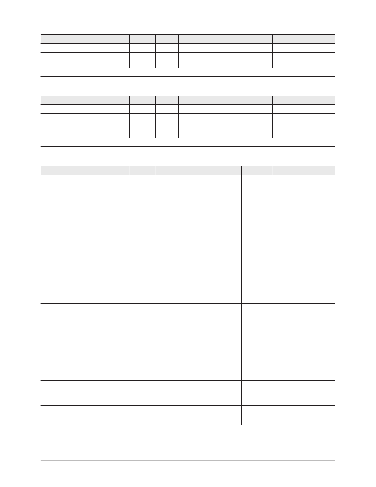
Quinta Pro 30 45 65 90 115
Electrical protection index
(1)
IP
X4D
(3)
X4D
(3)
X4D
(3)
X4D
(3)
X4D
(3)
Fuses Main
PCU
A 6.3
2.0
6.3
2.0
6.3
2.0
6.3
2.0
6.3
2.0
(1) Splashproof; under certain conditions, the boiler may be installed in damp areas, such as bathrooms.
Tab.6 Other data
Quinta Pro 30 45 65 90 115
Total weight (empty) kg 53 53 60 67 68
Minimum mounting weight
(1)
kg 49 49 56 65 65
Average acoustic level at a distance
of one metre from the boiler
dB(A) 38 45 45 52 51
(1) Without front panel.
Tab.7 Technical parameters
Quinta Pro 30 45 65 90 115
Condensing boiler Yes Yes Yes Yes Yes
Low-temperature boiler
(1)
Yes Yes Yes Yes Yes
B1 boiler No No No No No
Cogeneration space heater No No No No No
Combination heater Yes Yes Yes No No
Rated heat output
Prated
kW 29 40 61 84 107
Useful heat output at nominal heat
output and high temperature oper
ation
(2)
P
4
kW 29.3 40.0 61.0 84.2 107.0
Useful heat output at 30% of rated
heat output and low temperature
regime
(5)
P
1
kW 9.8 13.4 20.3 27.9 35.7
Seasonal space heating energy effi
ciency
ƞ
s
% 93 93 93 - -
Useful efficiency at rated heat out
put and high temperature regime
(6)
ƞ
4
% 87.8 87.6 88.6 88.2 87.5
Useful efficiency at 30% of rated
heat output and low temperature
regime
(5)
ƞ
1
% 97.7 97.7 98.1 97.4 97.3
Auxiliary electricity consumption
Full load
elmax
kW 0.039 0.068 0.088 0.125 0.199
Part load
elmin
kW 0.018 0.018 0.023 0.020 0.045
Standby mode
P
SB
kW 0.005 0.005 0.006 0.004 0.007
Other items
Standby heat loss
P
stby
kW 0.101 0.101 0.110 0.123 0.123
Ignition burner power consumption
P
ign
kW - - - - -
Annual energy consumption
Q
HE
kWh
GJ
- - - - -
Sound power level, indoors
L
WA
dB 46 53 53 60 59
Emissions of nitrogen oxides NO
X
mg/kWh 32 33 29 41 41
(1) Low temperature means 30°C for condensing boilers, 37°C for low temperature boilers and 50°C (at heater inlet) for other heating appli
ances.
(2) High temperature operation means 60°C return temperature at heater inlet and 80°C feed temperature at heater outlet.
3 Technical specifications
123157 - v.06 - 24022015 13
See
The back cover for contact details.
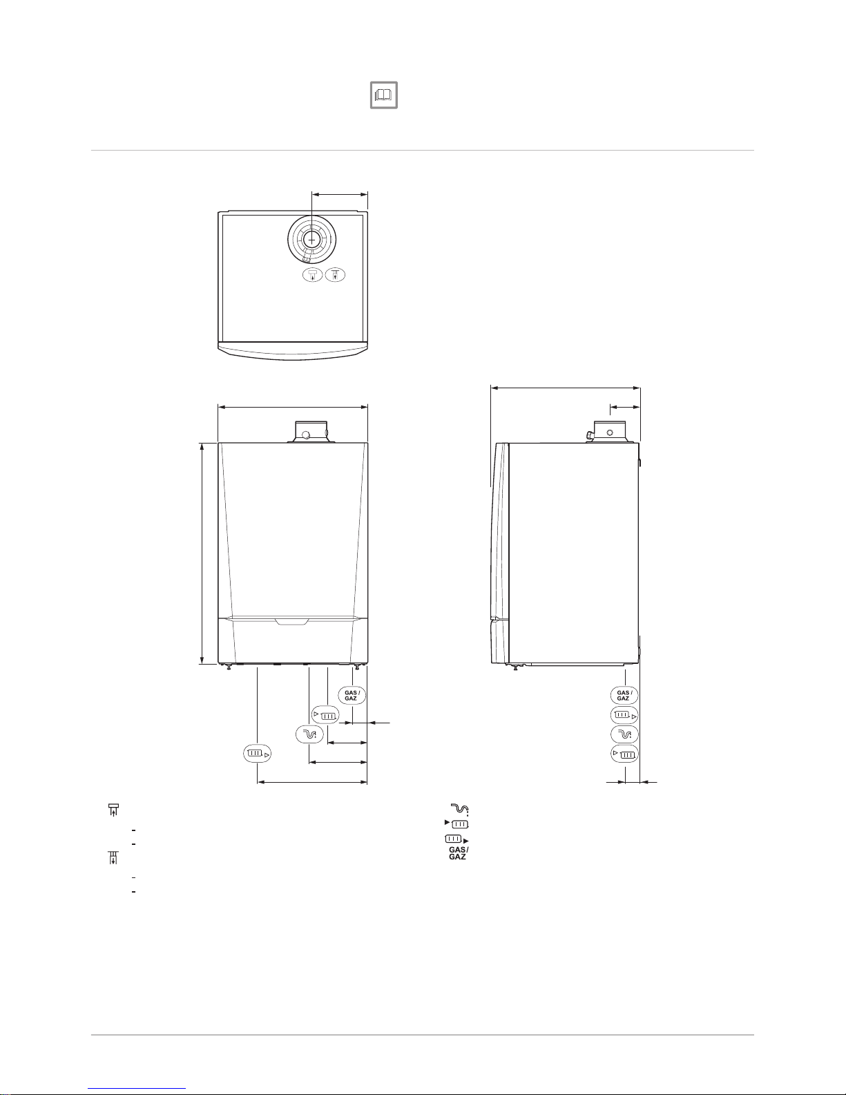
3.3 Dimensions and connections
Fig.1 Dimensions
AD-0000017-01
191
500
750
500
100
50
50
130
191
365
Flue gas outlet connection:
Ø 80 mm (≤ 45 kW)
Ø 100 mm (≥ 65 kW)
Air supply connection:
Ø 125 mm (≤ 45 kW)
Ø 150 mm (≥ 65 kW)
Siphon connection, 32 mm
CH supply connection; 1 ¼ inch male thread
CH return connection; 1 ¼ inch male thread
Gas connection; ¾ inch male thread
3 Technical specifications
14 123157 - v.06 - 24022015
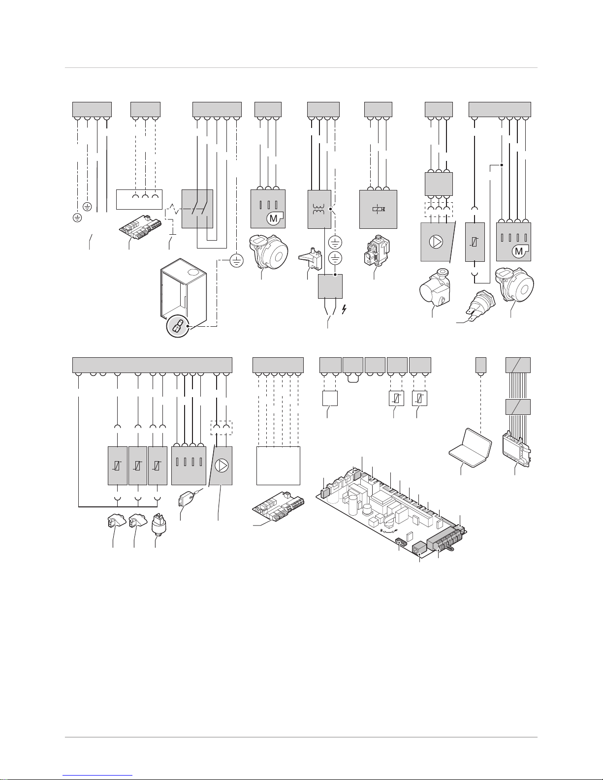
3.4 Electrical diagram
Fig.2 Electrical diagram
AD-0000062-01
X1
X14
X13
X12
X3
X2
X4
X5
X6
X7
X8
X9
X10
X11
X13
1
X6
1 2 3
GN/
YW
WH
BL
153
X21
X8
1 2 3
BR
BL
GN/
YW
2 1 3
X81
3 1 2
X11
1 2 3 4 5 6
WH
GY
OR
RD
GN
YW
X5
2 3 4 1
BK
BL
GN/
YW
GY
1 23
X51
12 13
BK
BK
1 2
X116
9
RD
1
BK
1
2 2
X115
8
BL
1
2
X114
10 11
BK
BK
3 1
X112
2 3
X10
4 5 7 6
X111
BK
BK
BK
BK
1 2 3 4
X9
2 3 4 5
X91
BK
BK
BK
BK
1 2 4 5
1
BK
BK
1
2
X117
X4
1 2 3
X41
BR
BL
GN/
YW
3 1 2
230V, 50Hz
LN
X2
1 32
BL
BR
GN/
YW
2 31
K1
X1
1 32
BR
BL
4
X14
1 10
1 10
X3
4 3 2 15
BR
BL
BR
BL
GN/
YW
3 1
4 2
X51
X12
3 4 5 61 2 7 8
9 1 0
GN/
YW
GN/
YW
1 2 3
4 7
8
13 14
15 16 17
18 19
121110
4
5
6
2
9
1
Power supply (P)
2
Extended PCB (SCU)
3
On/off switch (S)
4
Fan (FAN)
5
Ignition transformer (IT)
6
Ignition pin (E)
7
Gas combination block (GB)
8
Circulating pump (pump A)
9
High limit switch (HLS)
10
Return sensor (RTS)
11
Flow sensor (FTS)
12
Pressure switch (PS)
13
Storage parameter (PSU)
14
Circulating pump (PWM pump)
15
Thermostat (OT)
16
Outside sensor (OS)
17
Calorifier sensor (WS)
18
Computer connection (PC)
19
Display (DIS)
3 Technical specifications
123157 - v.06 - 24022015 15
4 Description of the product
4.1 General description
The Quinta Pro boiler is a high-efficiency wall-hung gas boiler with the fol
lowing properties:
High-efficiency heating.
Option to produce domestic hot water using a separate hot water appli
ance.
Limited emissions of polluted substances.
Ideal choice for cascade configurations.
4.2 Operating principle
4.2.1 Circulating pump
The boiler is supplied without a pump. Take the boiler resistance and sys
tem resistance into account when selecting a pump.
Caution
The pump may have a maximum input of 200 W. Use an auxiliary
relay for a pump with greater power.
See
Technical data, page 11
If possible, install the pump directly under the boiler on the return connec
tion.
For more information, see
Connecting the heating circuit, page 22
4.2.2 Cascade system
The boiler is ideally suited for a cascade system. There are a number of
standard solutions available.
Note
Contact us for more information.
4.2.3 Water flow
The modulating control of the boiler limits the maximum temperature differ
ence between the flow and return and the maximum rise velocity of the
flow temperature. As a result, the boiler is virtually unaffected by low water
flow. In all cases, maintain a minimum water flow of 0.4 m
3
/h. If progres
sive calorifier control is activated with parameter , then maintain a
minimum water flow of 0.8 m
3
/h.
4.2.4 Calorifier connection
A calorifier can be connected to the boiler. Our range includes various cal
orifiers.
Note
Contact us for more information.
Connect the calorifier to the boiler with a calorifier pump. A three-way
valve is not suitable due to the hydraulic resistance. An optional PCB is re
quired to connect a calorifier pump.
4 Description of the product
16 123157 - v.06 - 24022015
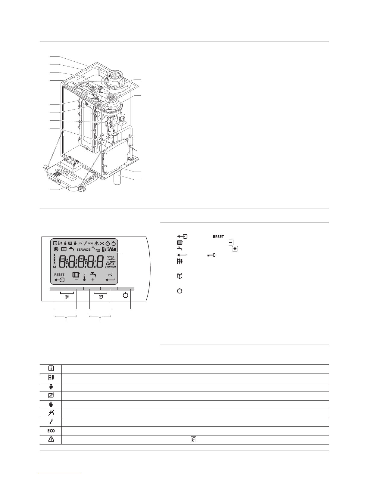
4.3 Main components
1
Flue gas outlet/air supply
2
Casing/air box
3
Heat exchanger (CH)
4
Flue gas measuring point
5
Ionisation/ignition electrode
6
Mixer tube
7
Combined gas valve unit
8
Air intake silencer
9
Instrument box
10
Siphon
11
Housing for PCBs
12
Fan
13
Water flow pipe
4.4 Control panel description
4.4.1 What each key means
1
Display
2
Escape or key
3
CH temperature or key
4
DHW temperature or key
5
Enter or Cancel key lockout
6
Chimney-sweeping keys
Press the 2 and 3 keys simultaneously.
7
Menu keys
Press the 4 and 5 keys simultaneously.
8
On/off switch
4.4.2 Meaning of the symbols on the display
Tab.8 Symbols on the display
Information menu: Read out various current values.
Chimney-sweeping position: Forced high or low load for O2/CO2 measurement.
User menu: Parameters at user level can be changed.
Central heating function off: The heating function is deactivated.
Manual mode: Boiler is set to manual mode.
DHW function off: The DHW function is switched off.
Service menu: Parameters at installer level can be changed.
ECO setting: The economy setting is activated.
Fault: Boiler indicates a fault. This can be seen from the code and red display.
Fig.3 Main components
AD-0000011-01
8
7
4
5
5
6
2
1
3
9
11
10
12
13
Fig.4 Control panel
AD-0000065-01
1
2 3 4 5 8
6 7
4 Description of the product
123157 - v.06 - 24022015 17
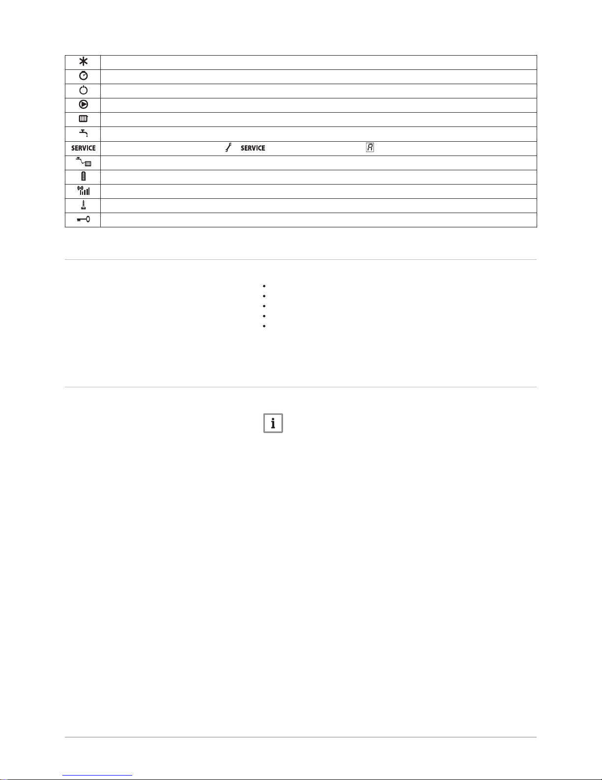
Frost protection: Boiler is running in frost protection mode.
Hour counter menu: Read out the operating hours, number of successful starts and hours on mains supply.
On/off switch: After 5 lockouts, the boiler must be switched off/on again.
Circulating pump: The pump is running.
CH function: Access to CH temperature parameter.
DHW function: Access to DHW temperature parameter.
Yellow display with the symbols: + + (maintenance message).
Water pressure: The water pressure is too low.
Battery symbol: Status of battery in wireless controller.
Signal strength symbol: Signal strength of the wireless controller.
Burner level: Boiler is running at full or part load.
Key lockout: Key lockout is activated.
4.5 Standard delivery
The delivery includes:
The boiler, with mains lead
Suspension bracket and fasteners for wall mounting
Mounting template
Connection cable for pump (Quinta Pro 90/115)
Documentation
This manual only deals with the standard scope of supply. For the installa
tion or mounting of any accessories delivered with the boiler, refer to the
corresponding mounting instructions.
4.6 Accessories and options
Various accessories can be obtained for the boiler.
Note
Contact us for more information.
4 Description of the product
18 123157 - v.06 - 24022015
5 Before installation
5.1 Installation regulations
Warning
The installer must be registered with Gas Safe and have the cor
rect ACS qualifications.
Note
Practical guidelines — see the latest version.
5.2 Choice of the location
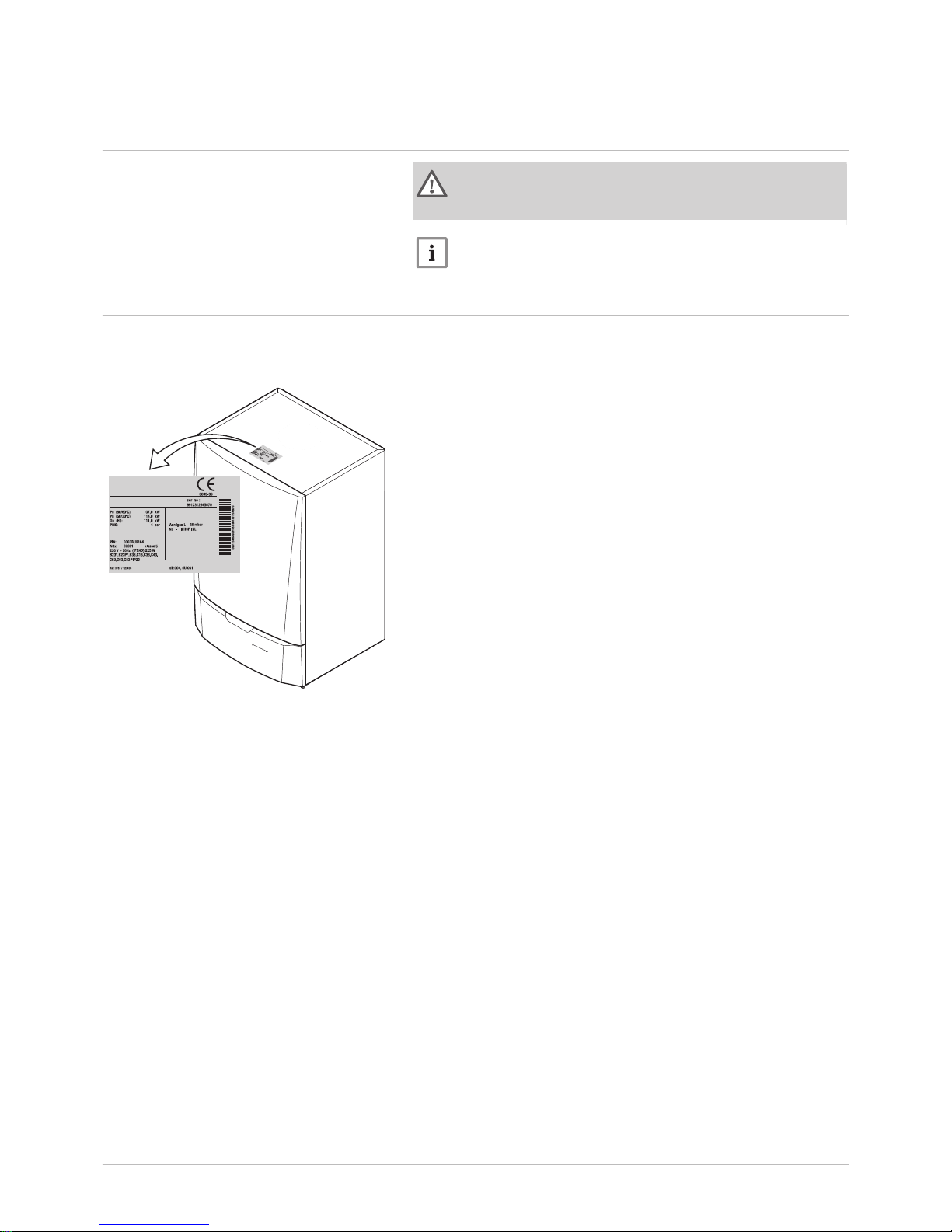
5.2.1 Type plate
The type plate on top of the boiler features the boiler serial number and
important boiler specifications, for example the model and unit category.
The dF and dU codes are also stated on the type plate.
Fig.5
Position of type plate
AD-0000013-01
5 Before installation
123157 - v.06 - 24022015 19
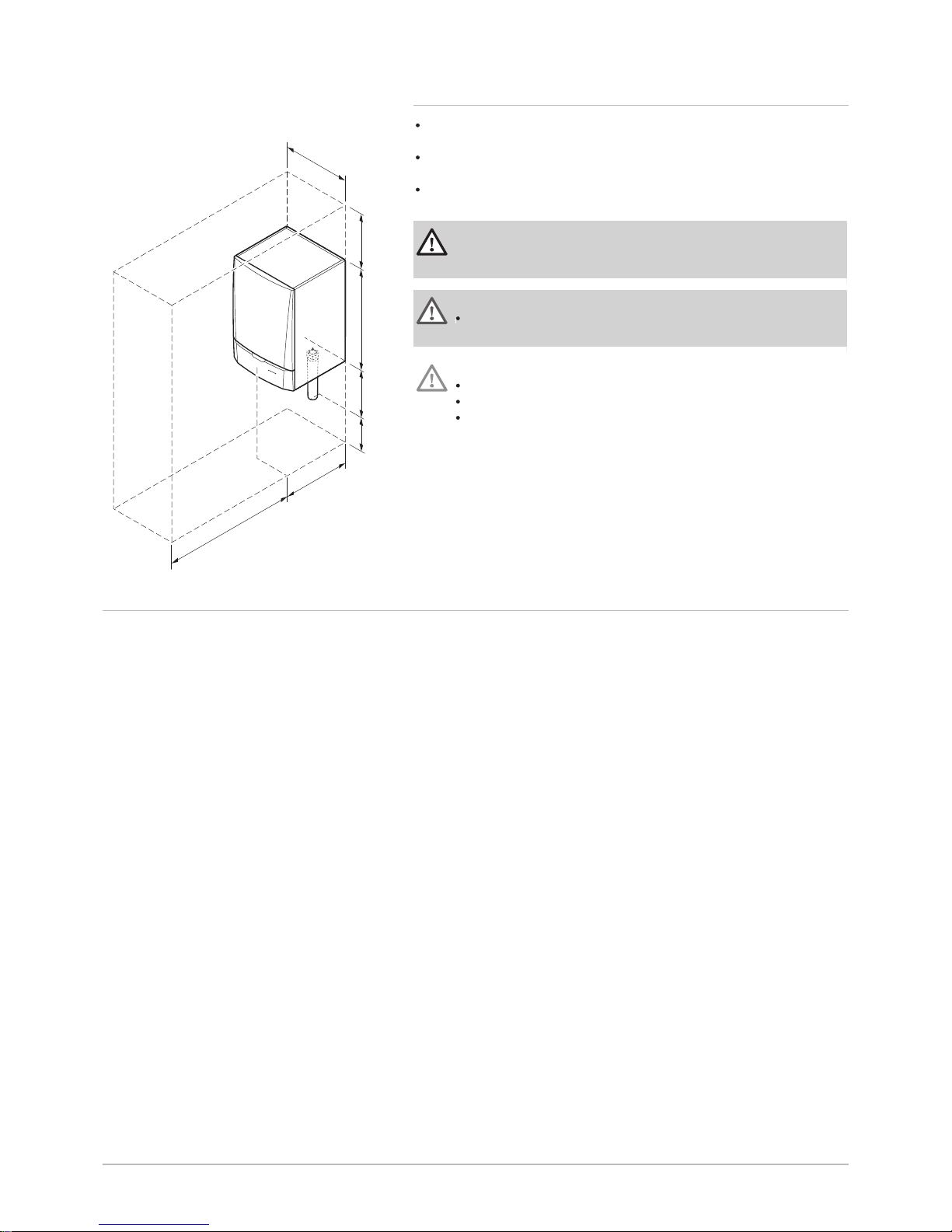
5.2.2 Boiler position
Use the guidelines and the required installation space as a basis for de
termining the correct place to install the boiler.
When determining the correct installation space, take account of the
permitted position of the flue gas discharge and/or air supply outlet.
Ensure that there is sufficient space around the boiler for good access
and ease of maintenance.
Danger
It is forbidden to store, even temporarily, combustible products
and substances in the boiler or near the boiler.
Warning
Fix the appliance to a solid wall capable of bearing the weight of
the boiler when full of water and fully equipped.
Caution
The boiler must be installed in a frost-free area.
The boiler must have an earthed electrical connection.
A connection to the sewer must be present for the condensate
drain close to the boiler.
5.3 Ventilation
The installation must comply with BS 5540 (part 1 + 2), BS 6640 and
IGUP/10.
Fig.6 Installation area
AD-0000014-01
500
min.1000
500
min.
400
350
min.
250
750
5 Before installation
20 123157 - v.06 - 24022015
6 Installation
6.1 General
Warning
The boiler must be installed by a qualified installer in accordance
with local and national regulations.
6.2 Preparation
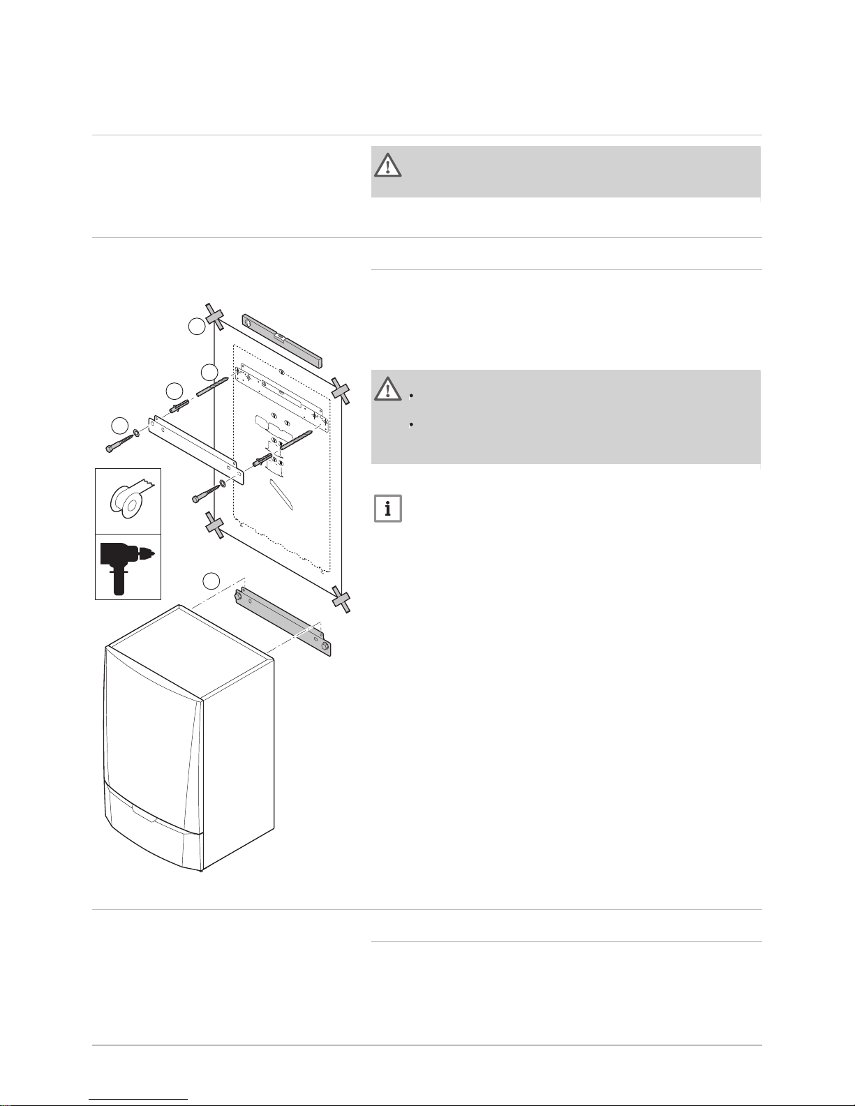
6.2.1 Positioning the boiler
The fitting bracket on the back of the casing can be used to mount the
boiler directly on the suspension bracket.
The boiler is supplied with a mounting template.
1. Attach the mounting template of the boiler to the wall using adhesive
tape.
Warning
Use a level to check whether the mounting template is hanging
perfectly horizontally.
Protect the boiler against building dust and cover the connection
points for the flue gas outlet and air supply. Only remove this
cover to assemble the relevant connections.
2. Drill 2 holes of Ø 10 mm.
Note
The extra holes are intended for use in the event that one of the
two fastening holes is not suitable for correct fastening of the plug.
3. Fit the Ø 10 mm plugs.
4. Attach the suspension bracket to the wall with the Ø 10 mm bolts
supplied.
5. Mount the boiler on the suspension bracket.
6.3 Water connections
6.3.1 Rinsing the system
The installation must be cleaned and flushed in accordance with BS 7593
(2006).
Before a new CH boiler can be connected to an existing or new installa
tion, the entire installation must be thoroughly cleaned and flushed. This
step is absolutely crucial. The flushing helps to remove residue from the
Fig.7 Mounting the boiler
AD-0000018-01
2
1
5
4
3
6 Installation
123157 - v.06 - 24022015 21
installation process (weld slag, fixing products etc.) and accumulations of
dirt (silt, mud etc.)
Note
Flush the CH installation with a volume of water equivalent to at
least three times the volume of the CH installation. Flush the DHW
pipes with at least 20 times the volume of the pipes.
Note
Due to the presence of an aluminium heat exchanger, suitable
chemicals and the correct use of these chemicals should be dis
cussed with specialist water treatment companies.
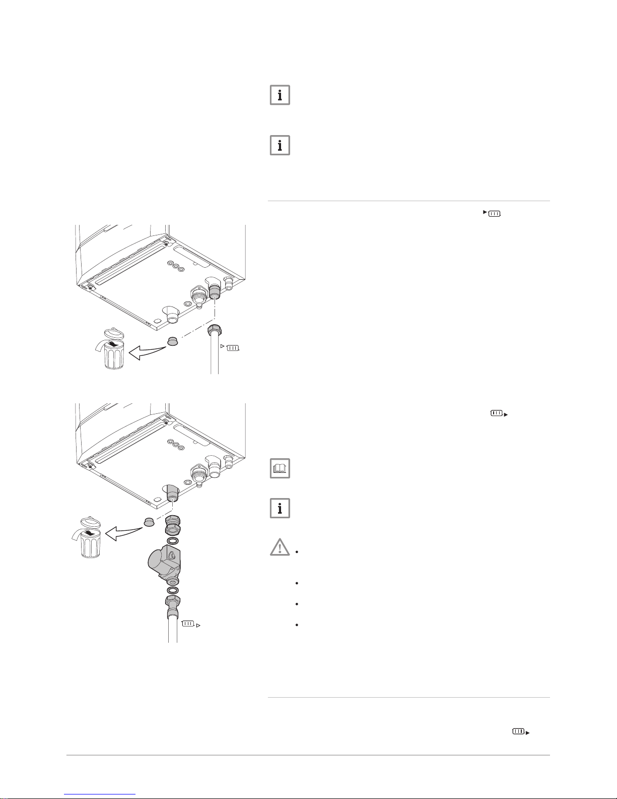
6.3.2 Connecting the heating circuit
1. Remove the dust cap from the CH flow connection at the bot
tom of the boiler.
2. Fit the outlet pipe for CH water to the CH flow connection.
3. For filling and tapping the boiler, install a filling and drain valve in the
system.
4. Remove the dust cap from the CH return connection at the bot
tom of the boiler.
5. Fit the inlet pipe for CH water to the CH return connection.
6. Install the pump in the CH return pipe (if applicable).
See
For the pump's electrical connection: Connecting the pump, page
30
Note
Fit a service shut-off valve in the CH flow pipe and the CH return
pipe to facilitate servicing work.
Caution
When fitting service shut-off valves, position the filling and drain
valve, the expansion vessel and the safety valve between the
shut-off valve and the boiler.
Carry out any welding work required at a safe distance from the
boiler or before the boiler is fitted.
If using synthetic pipes, follow the manufacturer's (connection)
instructions.
When installing open-vented systems, the cold feed and expan
sion tank heights must comply with the requirements laid down
in the Health and Safety Executive publication PM5. The Quinta
Pro boilers require a minimum static height of 3 m (Quinta Pro
30/45/65/90) or 5 m (Quinta Pro 115).
6.3.3 Connecting the expansion vessel
1. Ensure that there is an expansion vessel with the correct volume
and inlet pressure.
2. Fit the expansion vessel on the central heating return pipe
Fig.8 Connecting the CH flow
AD-0000022-01
Fig.9 Connecting the CH return
AD-0000023-01
6 Installation
22 123157 - v.06 - 24022015
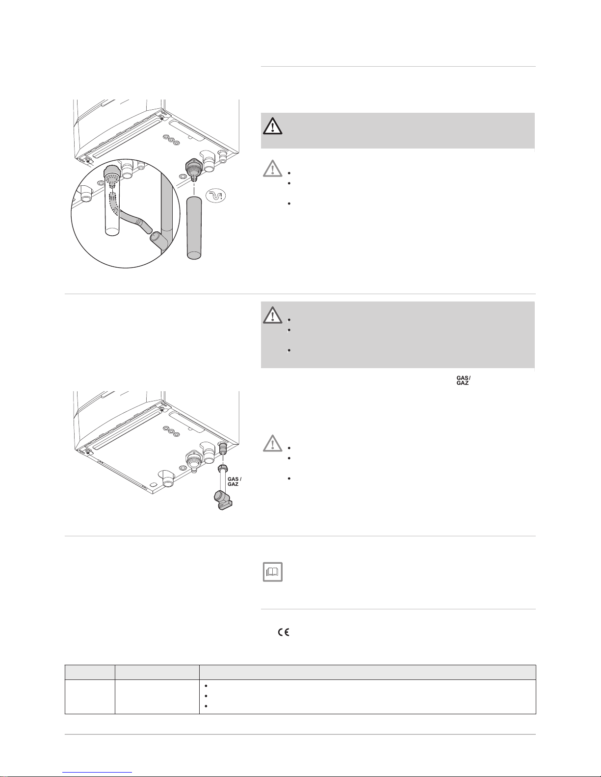
6.3.4 Connecting the condensate discharge pipe
1. Fit a plastic drain pipe of Ø 32 mm or larger, terminating in the drain.
2. Insert the flexible condensate drain hose into the pipe.
3. Fit a stench-trap or siphon in the drain pipe.
Danger
The siphon must always be filled with water. This prevents flue
gases from entering the room.
Caution
Never seal the condensate drain.
The drain pipe must slope down at least 30 mm per metre, the
maximum horizontal length is 5 metres.
Condensed water must not be discharged into a gutter.
6.4 Gas connection
Warning
Before starting work on the gas pipes, turn off the main gas tap.
Before installing, check that the gas meter has sufficient capaci
ty. Take into account the consumption of all appliances.
Notify the local energy company if the gas meter has insufficient
capacity.
1. Remove the dust cap from the gas supply pipe at the bottom of
the boiler.
2. Fit the gas supply pipe.
3. Fit a gas tap in this pipe, directly underneath the boiler.
4. Fit the gas pipe to the gas tap.
Caution
Remove dirt and dust from the gas pipe.
Always perform welding work at a sufficient distance from the
boiler.
Place a gas filter to prevent pollution of the gas valve unit.
6.5 Air supply/flue gas connections
The boiler is suitable for the following types of flue gas connections:
For more information, see
Certifications, page 11
6.5.1 Classification
This classification is specified in more detail in the table in accordance
with .
Tab.9 Types of flue gas connections
Type Version Description
B23
B23P
(1)
Open Without down-draught diverter.
Flue gas discharge via the roof.
Air from the installation area.
Fig.10 Connecting the condensate dis
charge pipe
AD-0000024-01
Fig.11 Connecting the gas pipe
AD-0000025-01
6 Installation
123157 - v.06 - 24022015 23
Type Version Description
B33 Open Without down-draught diverter.
Joint flue gas discharge via the roof.
Flue gas discharge rinsed with air, air from the installation area (special construction).
C13 Closed Discharge in the outside wall.
Inlet opening for the air supply is in the same pressure zone as the discharge (e.g. a
combined outside wall feed-through).
C33 Closed Flue gas discharge via the roof.
Inlet opening for the air supply is in the same pressure zone as the discharge (e.g. a
concentric roof feed-through).
C43
(2)
Closed/cascade Joint air supply and flue gas discharge duct (CLV system):
Concentric.
Eccentric: air supply from the shaft.
Cascade overpressure
C53 Closed Closed unit.
Separate air supply duct.
Separate flue gas discharge duct.
Discharging into various pressure areas.
C63 Closed This type of unit is supplied by the manufacturer without a supply and discharge sys
tem.
C83
(3)
Closed The appliance can be connected to a semi-CLV system (with common flue gas outlet).
C93
(4)
Closed Air supply and flue gas discharge duct in shaft or ducted:
Concentric.
Eccentric: air supply from the shaft.
Flue gas discharge via the roof.
Inlet opening for the air supply is in the same pressure zone as the discharge.
(1) Also pressure class P1
(2) EN 15502-2-1: 0.5 mbar suction due to depression
(3) 4 mbar depression can occur
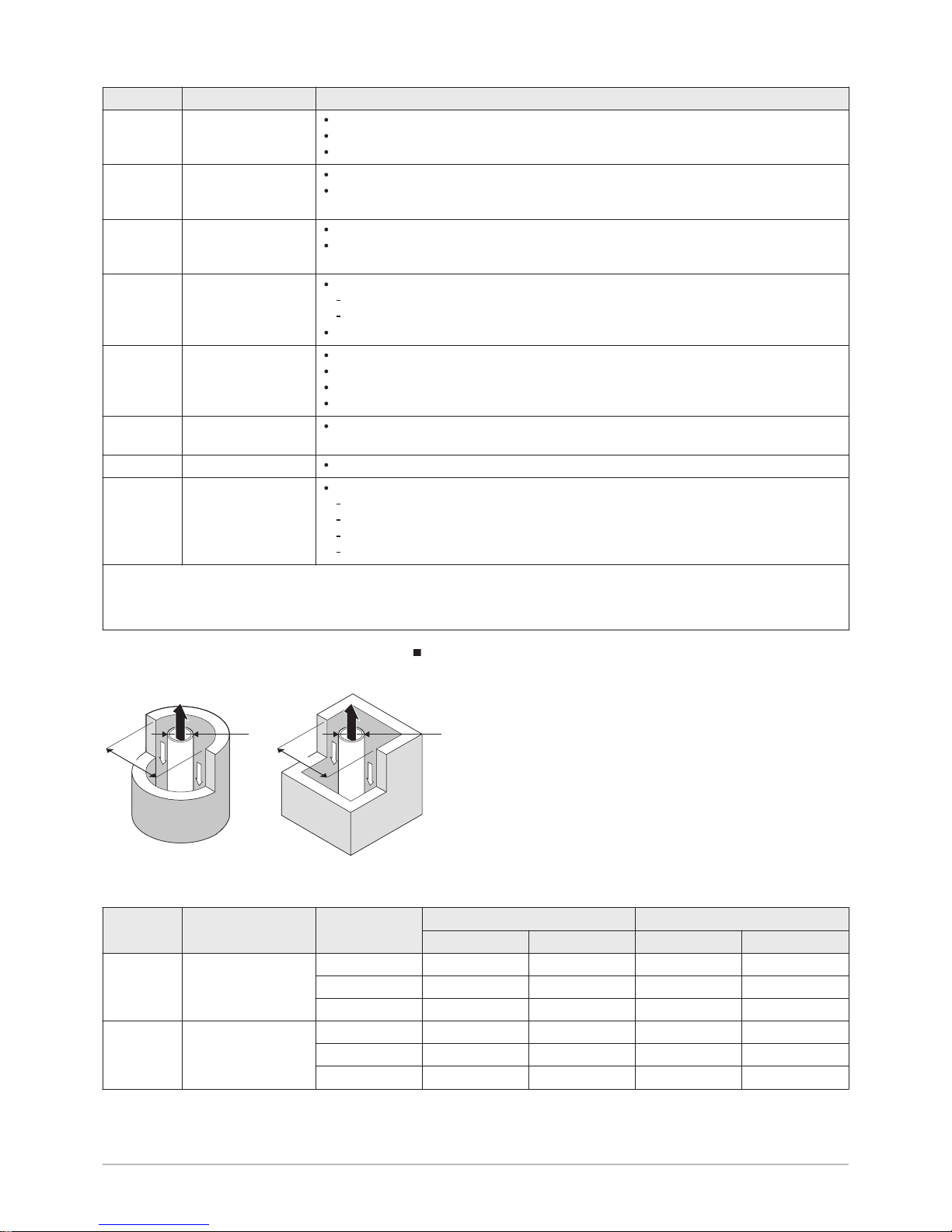
(4) See table for minimum dimensions of shaft or duct
Shaft dimensions
Fig.12
Minimum dimensions of shaft or duct
AD-3000330-01
□
D
Ø
D
Tab.10 Minimum dimensions of shaft or duct
Type Version Diameter (D) Without air supply With air supply
Ø duct □ duct Ø duct □ duct
C93 Rigid 60 mm 110 mm 110 x 110 mm 120 mm 110 x 110 mm
80 mm 130 mm 130 x 130 mm 140 mm 130 x 130 mm
100 mm 160 mm 160 x 160 mm 170 mm 160 x 160 mm
C93 Flexible 60 mm 110 mm 110 x 110 mm 120 mm 110 x 110 mm
80 mm 130 mm 130 x 130 mm 145 mm 130 x 130 mm
100 mm 160 mm 160 x 160 mm 170 mm 160 x 160 mm
6 Installation
24 123157 - v.06 - 24022015
Type Version Diameter (D) Without air supply With air supply
Ø duct □ duct Ø duct □ duct
C93 Concentric 60/100 mm 120 mm 120 x 120 mm 120 mm 120 x 120 mm
80/125 mm 145 mm 145 x 145 mm 145 mm 145 x 145 mm
100/150 mm 170 mm 170 x 170 mm 170 mm 170 x 170 mm
6.5.2 Outlets
Drain systems (roof feed-through and outside wall feed-through) must be
supplied by the following manufacturers:
Centrotherm
Cox Geelen
Muelink & Grol
Natalini
Poujoulat
Ubbink
Note
Where regulations stipulate that a wire grille must be fitted, use a
suitable grille made from stainless steel. There must be a mini
mum distance of 50 mm between each part of the outlet and the
grille.
Boiler-specific roof and outside wall feed-through kits are also available.
Note
Contact us for more information.
6.5.3 Length of the air and flue gas pipes
Note
When using bends, the maximum chimney length (L) must be
shortened according to the reduction table.
The boiler is also suitable for longer chimney lengths and diam
eters other than those specified in the tables. Contact us for
more information.
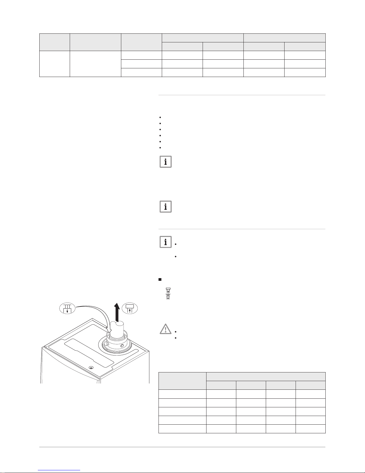
Room-ventilated version (B23, B23P, B33)
Flue gas outlet connection
Air supply connection
With a room-ventilated version, the air supply opening stays open; only the
flue gas outlet opening is connected. This will ensure that the boiler ob
tains the necessary combustion air directly from the installation area.
Caution
The air supply opening must stay open.
The installation area must be equipped with the necessary air
supply openings. These openings must not be obstructed or
shut off.
Tab.11 Maximum chimney length (L)
Quinta Pro Diameter
80 mm 90 mm 100 mm 110 mm
30 40 m 40 m 40 m 40 m
45 33 m 40 m 40 m 40 m
65 10 m 18 m 27 m 40 m
90 9 m 16 m 24 m 40 m
115 8 m 12 m 19 m 37 m
Fig.13 Room-ventilated version
AD-0000028-01
L
=
6 Installation
123157 - v.06 - 24022015 25
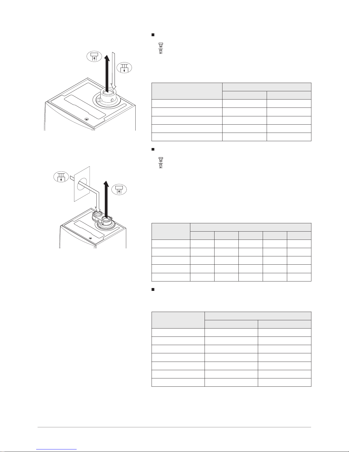
Room-sealed version (C13, C33, C43, C63, C93)
Flue gas outlet connection
Air supply connection
With a closed version, both the flue gas outlet and the air supply openings
are connected (concentrically).
Tab.12 Maximum chimney length (L)
Quinta Pro Diameter
80–125 mm 100–150 mm
30 20 m 20 m
45 16 m 20 m
65 - 13 m
90 - 13 m
115 - 7 m
Connection in different pressure areas (C53, C83)
Flue gas outlet connection
Air supply connection
A 100/100 mm flue gas adapter (accessory) must be fitted for this connec
tion.
Combustion air supply and flue gas discharge are possible in different
pressure areas and semi-CLV systems, with the exception of the coastal
area. The maximum permitted height difference between the combustion
air supply and the flue gas outlet is 36 m.
Tab.13 Maximum chimney length (L) in the various pressure zones
Quinta Pro Diameter
80 mm 90 mm 100 mm 110 mm 130 mm
30 20 m 36 m 36 m 36 m 36 m
45 20 m 36 m 36 m 36 m 36 m
65 - 2 m 8 m 34 m 36 m
90 - - 4 m 32 m 36 m
115 - - - 24 m 36 m
Reduction table
Tab.14 Pipe reduction for each element used (parallel)
Diameter
Pipe reduction
45° bend 90° bend
60 mm 0.9 m 3.1 m
70 mm 1.1 m 3.5 m
80 mm 1.2 m 4.0 m
90 mm 1.3 m 4.5 m
100 mm 1.4 m 4.9 m
110 mm 1.5 m 5.4 m
130 mm 1.6 m 6.2 m
Fig.14 Room-sealed version (concentric)
AD-0000029-01
L
=
Fig.15 Different pressure areas
AD-0000030-01
L
=
+
6 Installation
26 123157 - v.06 - 24022015
 Loading...