

REMEHA HFS 600, HFS 750 Installation And Service Manual
HFS
600 - 750
Installation and service manual
Powerful domestic water boiler
Great Britain
en

Dear customer,
Thank you for purchasing this appliance.
Be sure to read this manual carefully before using the product and keep it in a safe place for future use.
To ensure continued safe and proper operation, we recommend having the product serviced regularly. Our service and
customer service organisation can assist you with this.
We hope you will continue to enjoy the product for many years to come.

37651255 - v.01 - 23052016 HFS 650 / HSF 700
Table of contents
Table of contents
1 Introduction .......................................................................................4
1.1 Symbols used .................................................................................4
1.2 General information .............................................................................4
2 Safety instructions and recommendations . . . . . . . . . . . . . . . . . . . . . . . . . . . . . . . . . . . . . . . . . . . . . . . . . . . . . . . . . . . . . .5
3 Technical description................................................................................6
3.1 General description .............................................................................6
3.2 Technical data .................................................................................6
3.3 Description of operation ..........................................................................7
3.3.1 Filling the hot water boiler.................................................................7
3.3.2 Installation of a recirculation line............................................................8
4 Installation .......................................................................................10
4.1 Installation instructions..........................................................................10
4.1.1 Domestic water quality .....................................................................10
4.2 Scope of delivery ..............................................................................12
4.3 Placement ...................................................................................12
4.4 Main dimensions – Connections ..................................................................12
4.5 Mounting the appliance .........................................................................13
4.5.1 Installation of a recirculation line set........................................................13
4.5.2 Mounting the boiler .....................................................................14
4.6 Hydraulic examples ............................................................................16
4.7 Connections on the domestic water side ............................................................21
4.7.1 Special precautions ....................................................................21
4.7.2 Combination inlet group .................................................................21
4.7.3 Shut-off valves ........................................................................21
4.7.4 Cold water/domestic water connection ......................................................21
4.7.5 Tap water mixing valve ..................................................................21
4.7.6 Hot water recirculation line ...............................................................21
4.7.7 Measures to prevent backflow of heated water ...............................................22
4.8 Connection of the expansion vessels to the collector and heating circuit ...................................22
4.8.1 Boiler circuit ..........................................................................22
4.8.2 Collector circuit (on the boiler side) ........................................................22
4.9 Electrical connection ...........................................................................22
4.10 Commissioning ...............................................................................22
5 Inspection and maintenance.........................................................................23
5.1 Switching off during the summer: Safety through Steam Back ...........................................23
5.2 Maintenance .................................................................................23
6 Commissioning report..............................................................................24
6.1 System description.............................................................................24
6.2 Inspection of collector circuit supply and return lines...................................................24
6.3 Control station, verification of operation RemaSOL C2 .................................................24
6.4 System inspection .............................................................................25
6.5 Resetting ....................................................................................25
6.6 Remarks.....................................................................................26
7 Maintenance report ................................................................................27
7651255 - v.01 - 230520164 HFS 650 / HSF 700
1 Introduction
1 Introduction
1.1 Symbols used
This manual uses various danger levels to draw attention to the special
instructions. We do this to increase the safety of the user, to prevent
problems and to ensure the technical reliability of the device.
Danger
Chance of dangerous situations that can cause severe personal
injury.
Danger of electric shock
Danger of electric shock
Warning
Chance of dangerous situations that can cause minor personal
injury.
Attention
Chance of property damage.
Explanation
Attention, important information.
See
Reference to other manuals or other pages in this manual.
HW: hot water
1.2 General information
Congratulations! You have chosen a quality product. We advise you
to read the instructions below in order to ensure the optimal operation
of your installation. We are confident that this product will meet your
expectations. The manufacturer cannot be held liable for damage resulting
from incorrect use of the appliance, deficient or inadequate maintenance
or incorrect installation of the appliance (it is your responsibility to have
the installation performed by an authorised heating installer).

57651255 - v.01 - 23052016 HFS 650 / HSF 700
2 Safety instructions and recommendations
2 Safety instructions and recommendations
Attention
Installation, commissioning and maintenance must be performed by
a competent technician and in accordance with the applicable legal
requirements and supplied instructions.
Attention
Heating water and domestic water may not come into contact with
each other.
Regular maintenance of the appliance is necessary to ensure reliable and
safe operation. If the hot water boiler is modified in any way, the warranty
will be void.
7651255 - v.01 - 230520166 HFS 650 / HSF 700
3 Technical description
3 Technical description
3.1 General description
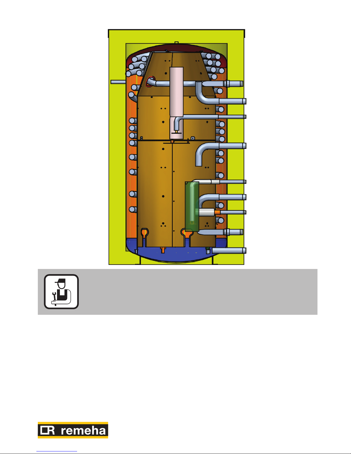
The HFS 600 / HFS 750 is a powerful hot water boiler for legionella-free
heating of domestic water based on continuous recirculation with heating
boiler and solar energy installation. The hot water boiler is suitable for
use where there is a high demand for hot water, in the types of situations
found in:
• Hotels
• Carecomplexes
• Apartmentcomplexes
• Campsites
• Sportsaccommodations
• Farm/cattleranches
• Processindustry
etc.
Description of the product:
• Steelboilervesselwithavolumeof600and750litresrespectively
• Boilervesselexternallyprotectedbyarust-inhibitinglayer,black
• Domesticwatercoilmadeofcorrugatedstainlesssteelpipe,
grade 1.4404
• Insulationofpolyesterfibre(120mm)withNeoporwhiteoutercovering.
• Incl.thermometermetimmersionsleeve
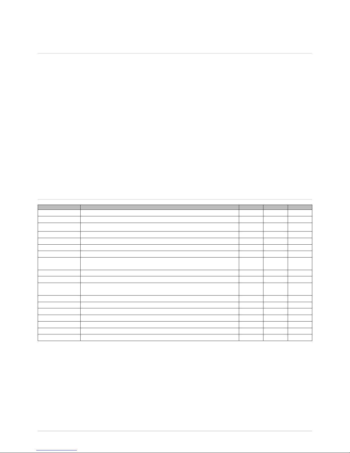
3.2 Technical data
Type HFS 600 750
Buffer vessel Nominalvolume Litre 620 750
Max. operating overpressure bar 6 6
Max. operating temperature °C 95 95
Heat exchanger Corrugated stainless steel coil Litre 46 52
Max. operating overpressure bar 8 8
Consumed energy at 35 K kW 150 195
Continuous capacity 35 K l/hr 3000 4800
Situation 1: Return line from the heating boiler connected to the upper
connection (connection 3 + 6, page 7)
Flow in 10 min. at 35 K (mixed) (1) l/10 min 750 990
Power index 18 45
Situation 2: Return line from the heating boiler connected to the lower
connection (connection 8, page 7)
Flow in 10 min. at 35 K (mixed) (1) l/10 min 900 1200
Power index(1) 25 62
Stand-by losses Vtotal = 55 °C (primary temperature) kWh/24 h 2.7 3
Cooling constant Cr 0.13 0.14
ErP data
Boiler volume V I 653 742
Standby heat loss S W 113 125
(1) Temperature cold water supply: 10 °C - Outlet temperature hot water unit: 45 °C - Primary temperature 80 °C
Target value hot water unit: 70 °C
77651255 - v.01 - 23052016 HFS 650 / HSF 700
3 Technical description
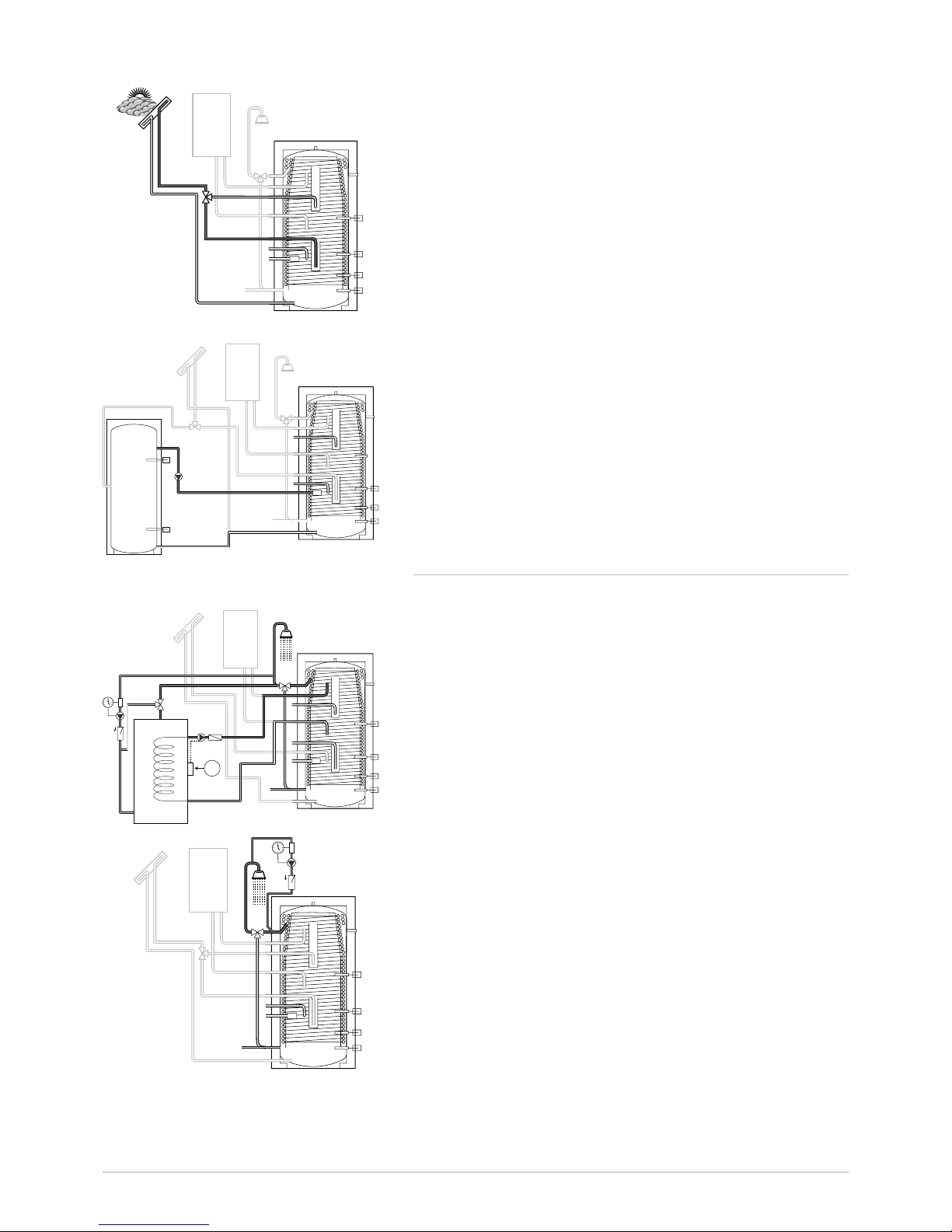
3.3 Description of operation
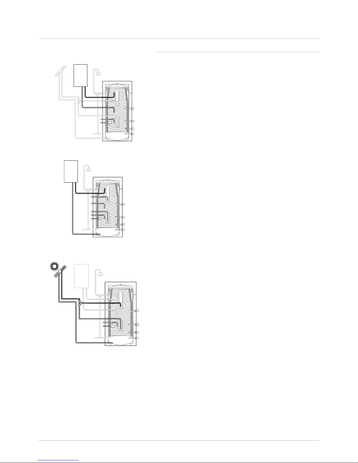
3.3.1 Filling the hot water boiler
Q Situation 1: Heating boiler + collector circuit
S2: Solar boiler sensor
Stb: Boiler sensor
Q Situation 2: Only heating boiler
HW: Boiler sensor
Q Situation 3a: Charging via the solar energy installation, at
top, with boiler
S2: Solar boiler sensor
Stb: Boiler sensor
WW
S2
Stb
KW
L000017-C
WW
KW
L000016-C
Stb
WW
S2
KW
L000019-C
7651255 - v.01 - 230520168 HFS 650 / HSF 700
Q Situation 3b: Charging via the solar energy installation, at
bottom, with boiler
S2: Solar boiler sensor
Stb: Boiler sensor
Q Situation 4: Filling / draining via buffer
S2: Solar boiler sensor
S4: Buffer - bottom
HW: Boiler sensor
S5: Buffer - top
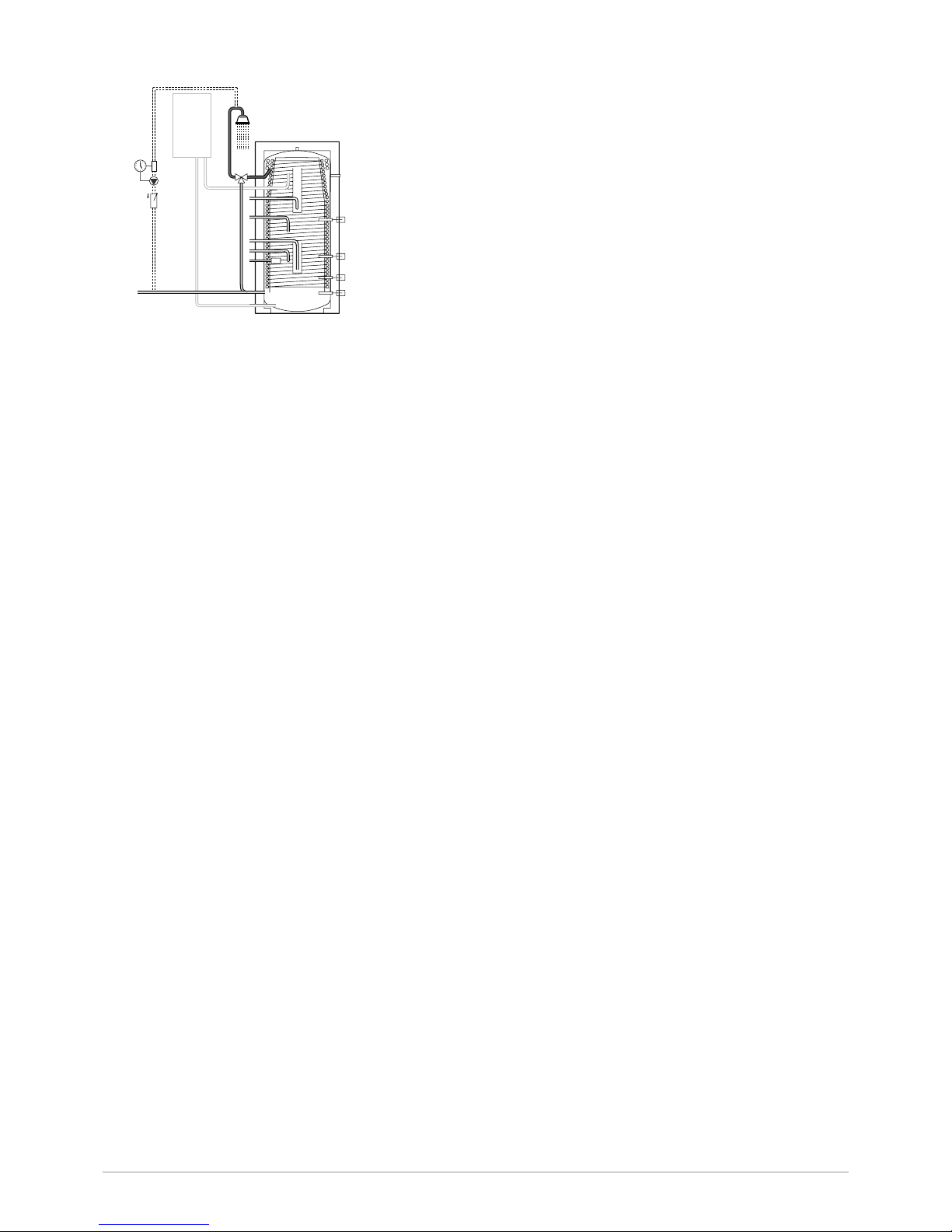
3.3.2 Installation of a recirculation line
Q Situation 1: Recirculation: use of a separate recirculation
buffer (with a flow rate loss of more than 250 l/hr: see
ISSO publication 55.1 section 4.2.3 Thermal management
concept).
Thermostat x °C
S2: Solar boiler sensor
Stb: Boiler sensor
Q Situation 2: Recirculation: use of optional recirculation
connection set 100020184 at a flow rate loss of up to
250 l/hr (see ISSO publication 55.1 section 4.2.3 Thermal
management concept).
S2: Solar boiler sensor
S4: Boiler sensor CH boiler
Stb
WW
S2
KW
L000020-C
WW
S2
KW
S5
S4
L000021-C
Stb
WW
S2
KW
1
L000024-C
Stb
WW
S2
KW
L000022-C
3 Technical description
97651255 - v.01 - 23052016 HFS 650 / HSF 700
Q Situation 3: Recirculation without collector circuit (at a
flow rate loss of more than 250 l/hr: see ISSO publication
55.1 section 4.2.3 Thermal management concept).
HW: Boiler sensor
WW
KW
L000025-D
3 Technical description

7651255 - v.01 - 2305201610 HFS 650 / HSF 700
4 Installation
4 Installation
4.1 Installation instructions
All aspects of the installation must be carried out in accordance with the
current regulations for work performed and technical systems in private,
public or other buildings.
Attention
The installation must be carried out in accordance with the current
regulations, best practices for technical work, and the instructions in
this manual.
4.1.1 Domestic water quality
Self-cleaning effect
Boilers with corrugated stainless steel coil for heating of domestic water
are insusceptible to deposits of pure lime (pure calcium). Pressure
differences in the pipe during opening and closing of the taps cause
pressure surges in the corrugated stainless steel coil. This causes the coil
to stretch slightly and then contract again.
These movements in the coil are sufficient to cause ‘normal’ lime deposits
(calcium) to flake off. The dissolved lime is flushed away when a tap is
opened.
Attention
This self-cleaning effect of the corrugated stainless steel coil in HFS
boilers is no longer sufficient when in addition to the lime (calcium)
there are also other substances such as free carbonic acid and
magnesium present in the water. When lime and free carbonic acid
are present in the water, these substances react to form ‘scale’.
The presence of magnesium in the water at a filling temperature
> 60 °C promotes the formation of scale.
Boiler scale, in contrast to lime, is not broken loose by the selfcleaning effect of the corrugated stainless steel coil but rather forms
larger deposits. When the pressure is relieved from the corrugated
stainless steel coil in the boiler, during maintenance for example,
boiler scale in solid form may break loose and clog the coil (heat
exchanger).
For domestic water containing these substances, the corrugated stainless
steel coil must be inspected regularly and decalcified with a softening
agent as necessary or a decalcification system must be installed in the
cold water supply line of the HFS domestic water boiler.
 Loading...