

HFS
600 - 750
Installation and service manual
Powerful domestic water boiler
Great Britain
en

Dear customer,
Thank you for purchasing this appliance.
Be sure to read this manual carefully before using the product and keep it in a safe place for future use.
To ensure continued safe and proper operation, we recommend having the product serviced regularly. Our service and
customer service organisation can assist you with this.
We hope you will continue to enjoy the product for many years to come.

37651255 - v.01 - 23052016 HFS 650 / HSF 700
Table of contents
Table of contents
1 Introduction .......................................................................................4
1.1 Symbols used .................................................................................4
1.2 General information .............................................................................4
2 Safety instructions and recommendations . . . . . . . . . . . . . . . . . . . . . . . . . . . . . . . . . . . . . . . . . . . . . . . . . . . . . . . . . . . . . .5
3 Technical description................................................................................6
3.1 General description .............................................................................6
3.2 Technical data .................................................................................6
3.3 Description of operation ..........................................................................7
3.3.1 Filling the hot water boiler.................................................................7
3.3.2 Installation of a recirculation line............................................................8
4 Installation .......................................................................................10
4.1 Installation instructions..........................................................................10
4.1.1 Domestic water quality .....................................................................10
4.2 Scope of delivery ..............................................................................12
4.3 Placement ...................................................................................12
4.4 Main dimensions – Connections ..................................................................12
4.5 Mounting the appliance .........................................................................13
4.5.1 Installation of a recirculation line set........................................................13
4.5.2 Mounting the boiler .....................................................................14
4.6 Hydraulic examples ............................................................................16
4.7 Connections on the domestic water side ............................................................21
4.7.1 Special precautions ....................................................................21
4.7.2 Combination inlet group .................................................................21
4.7.3 Shut-off valves ........................................................................21
4.7.4 Cold water/domestic water connection ......................................................21
4.7.5 Tap water mixing valve ..................................................................21
4.7.6 Hot water recirculation line ...............................................................21
4.7.7 Measures to prevent backflow of heated water ...............................................22
4.8 Connection of the expansion vessels to the collector and heating circuit ...................................22
4.8.1 Boiler circuit ..........................................................................22
4.8.2 Collector circuit (on the boiler side) ........................................................22
4.9 Electrical connection ...........................................................................22
4.10 Commissioning ...............................................................................22
5 Inspection and maintenance.........................................................................23
5.1 Switching off during the summer: Safety through Steam Back ...........................................23
5.2 Maintenance .................................................................................23
6 Commissioning report..............................................................................24
6.1 System description.............................................................................24
6.2 Inspection of collector circuit supply and return lines...................................................24
6.3 Control station, verification of operation RemaSOL C2 .................................................24
6.4 System inspection .............................................................................25
6.5 Resetting ....................................................................................25
6.6 Remarks.....................................................................................26
7 Maintenance report ................................................................................27
7651255 - v.01 - 230520164 HFS 650 / HSF 700
1 Introduction
1 Introduction
1.1 Symbols used
This manual uses various danger levels to draw attention to the special
instructions. We do this to increase the safety of the user, to prevent
problems and to ensure the technical reliability of the device.
Danger
Chance of dangerous situations that can cause severe personal
injury.
Danger of electric shock
Danger of electric shock
Warning
Chance of dangerous situations that can cause minor personal
injury.
Attention
Chance of property damage.
Explanation
Attention, important information.
See
Reference to other manuals or other pages in this manual.
HW: hot water
1.2 General information
Congratulations! You have chosen a quality product. We advise you
to read the instructions below in order to ensure the optimal operation
of your installation. We are confident that this product will meet your
expectations. The manufacturer cannot be held liable for damage resulting
from incorrect use of the appliance, deficient or inadequate maintenance
or incorrect installation of the appliance (it is your responsibility to have
the installation performed by an authorised heating installer).

57651255 - v.01 - 23052016 HFS 650 / HSF 700
2 Safety instructions and recommendations
2 Safety instructions and recommendations
Attention
Installation, commissioning and maintenance must be performed by
a competent technician and in accordance with the applicable legal
requirements and supplied instructions.
Attention
Heating water and domestic water may not come into contact with
each other.
Regular maintenance of the appliance is necessary to ensure reliable and
safe operation. If the hot water boiler is modified in any way, the warranty
will be void.
7651255 - v.01 - 230520166 HFS 650 / HSF 700
3 Technical description
3 Technical description
3.1 General description
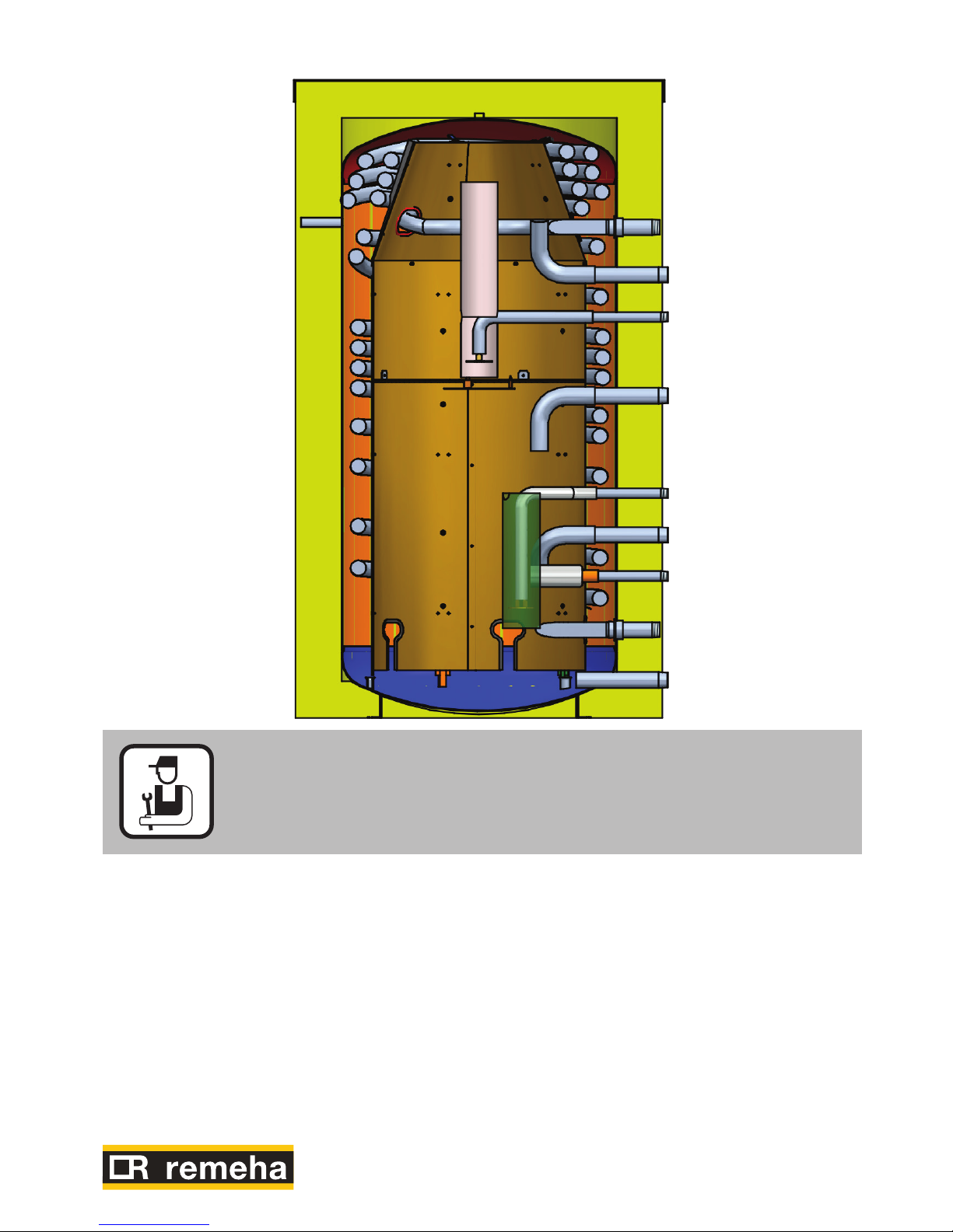
The HFS 600 / HFS 750 is a powerful hot water boiler for legionella-free
heating of domestic water based on continuous recirculation with heating
boiler and solar energy installation. The hot water boiler is suitable for
use where there is a high demand for hot water, in the types of situations
found in:
• Hotels
• Carecomplexes
• Apartmentcomplexes
• Campsites
• Sportsaccommodations
• Farm/cattleranches
• Processindustry
etc.
Description of the product:
• Steelboilervesselwithavolumeof600and750litresrespectively
• Boilervesselexternallyprotectedbyarust-inhibitinglayer,black
• Domesticwatercoilmadeofcorrugatedstainlesssteelpipe,
grade 1.4404
• Insulationofpolyesterfibre(120mm)withNeoporwhiteoutercovering.
• Incl.thermometermetimmersionsleeve
3.2 Technical data
Type HFS 600 750
Buffer vessel Nominalvolume Litre 620 750
Max. operating overpressure bar 6 6
Max. operating temperature °C 95 95
Heat exchanger Corrugated stainless steel coil Litre 46 52
Max. operating overpressure bar 8 8
Consumed energy at 35 K kW 150 195
Continuous capacity 35 K l/hr 3000 4800
Situation 1: Return line from the heating boiler connected to the upper
connection (connection 3 + 6, page 7)
Flow in 10 min. at 35 K (mixed) (1) l/10 min 750 990
Power index 18 45
Situation 2: Return line from the heating boiler connected to the lower
connection (connection 8, page 7)
Flow in 10 min. at 35 K (mixed) (1) l/10 min 900 1200
Power index(1) 25 62
Stand-by losses Vtotal = 55 °C (primary temperature) kWh/24 h 2.7 3
Cooling constant Cr 0.13 0.14
ErP data
Boiler volume V I 653 742
Standby heat loss S W 113 125
(1) Temperature cold water supply: 10 °C - Outlet temperature hot water unit: 45 °C - Primary temperature 80 °C
Target value hot water unit: 70 °C
77651255 - v.01 - 23052016 HFS 650 / HSF 700
3 Technical description
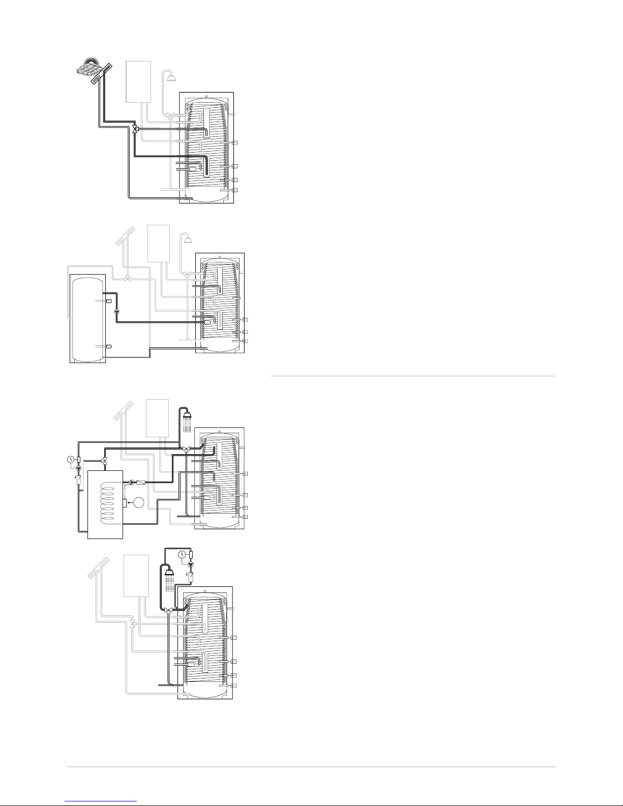
3.3 Description of operation
3.3.1 Filling the hot water boiler
Q Situation 1: Heating boiler + collector circuit
S2: Solar boiler sensor
Stb: Boiler sensor
Q Situation 2: Only heating boiler
HW: Boiler sensor
Q Situation 3a: Charging via the solar energy installation, at
top, with boiler
S2: Solar boiler sensor
Stb: Boiler sensor
WW
S2
Stb
KW
L000017-C
WW
KW
L000016-C
Stb
WW
S2
KW
L000019-C
7651255 - v.01 - 230520168 HFS 650 / HSF 700
Q Situation 3b: Charging via the solar energy installation, at
bottom, with boiler
S2: Solar boiler sensor
Stb: Boiler sensor
Q Situation 4: Filling / draining via buffer
S2: Solar boiler sensor
S4: Buffer - bottom
HW: Boiler sensor
S5: Buffer - top
3.3.2 Installation of a recirculation line
Q Situation 1: Recirculation: use of a separate recirculation
buffer (with a flow rate loss of more than 250 l/hr: see
ISSO publication 55.1 section 4.2.3 Thermal management
concept).
Thermostat x °C
S2: Solar boiler sensor
Stb: Boiler sensor
Q Situation 2: Recirculation: use of optional recirculation
connection set 100020184 at a flow rate loss of up to
250 l/hr (see ISSO publication 55.1 section 4.2.3 Thermal
management concept).
S2: Solar boiler sensor
S4: Boiler sensor CH boiler
Stb
WW
S2
KW
L000020-C
WW
S2
KW
S5
S4
L000021-C
Stb
WW
S2
KW
1
L000024-C
Stb
WW
S2
KW
L000022-C
3 Technical description
97651255 - v.01 - 23052016 HFS 650 / HSF 700
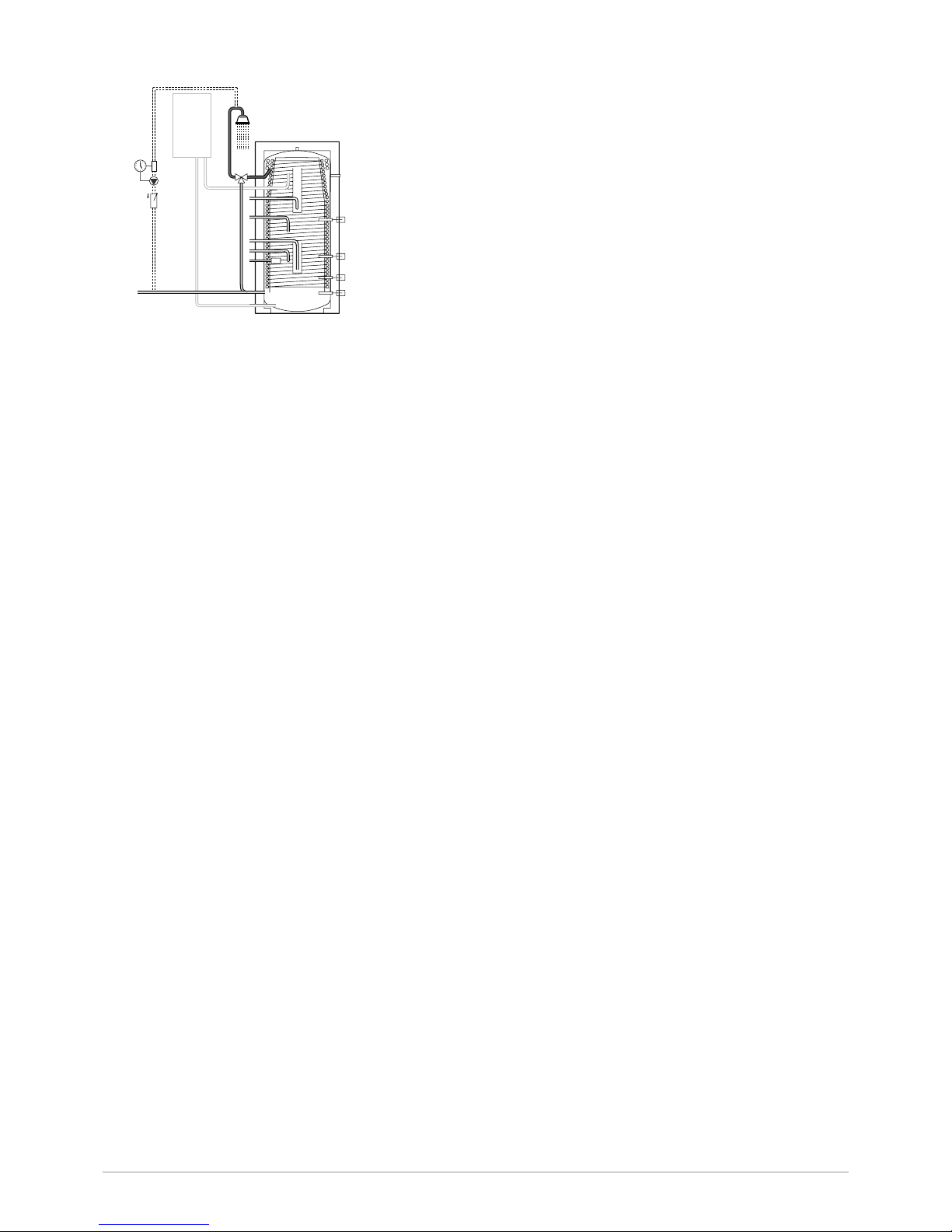
Q Situation 3: Recirculation without collector circuit (at a
flow rate loss of more than 250 l/hr: see ISSO publication
55.1 section 4.2.3 Thermal management concept).
HW: Boiler sensor
WW
KW
L000025-D
3 Technical description

7651255 - v.01 - 2305201610 HFS 650 / HSF 700
4 Installation
4 Installation
4.1 Installation instructions
All aspects of the installation must be carried out in accordance with the
current regulations for work performed and technical systems in private,
public or other buildings.
Attention
The installation must be carried out in accordance with the current
regulations, best practices for technical work, and the instructions in
this manual.
4.1.1 Domestic water quality
Self-cleaning effect
Boilers with corrugated stainless steel coil for heating of domestic water
are insusceptible to deposits of pure lime (pure calcium). Pressure
differences in the pipe during opening and closing of the taps cause
pressure surges in the corrugated stainless steel coil. This causes the coil
to stretch slightly and then contract again.
These movements in the coil are sufficient to cause ‘normal’ lime deposits
(calcium) to flake off. The dissolved lime is flushed away when a tap is
opened.
Attention
This self-cleaning effect of the corrugated stainless steel coil in HFS
boilers is no longer sufficient when in addition to the lime (calcium)
there are also other substances such as free carbonic acid and
magnesium present in the water. When lime and free carbonic acid
are present in the water, these substances react to form ‘scale’.
The presence of magnesium in the water at a filling temperature
> 60 °C promotes the formation of scale.
Boiler scale, in contrast to lime, is not broken loose by the selfcleaning effect of the corrugated stainless steel coil but rather forms
larger deposits. When the pressure is relieved from the corrugated
stainless steel coil in the boiler, during maintenance for example,
boiler scale in solid form may break loose and clog the coil (heat
exchanger).
For domestic water containing these substances, the corrugated stainless
steel coil must be inspected regularly and decalcified with a softening
agent as necessary or a decalcification system must be installed in the
cold water supply line of the HFS domestic water boiler.

117651255 - v.01 - 23052016 HFS 650 / HSF 700
4 Installation
Operation:
Flushing connection set HFS 600-750 for flushing the corrugated stainless
steel coil to remove deposits of boiler scale
Flushing provisions on the HFS:
The flushing provisions on the HFS must, in accordance with regulations,
consist of the following parts:
2 T-fittings, 2 shut-off valves
Installation: in the cold water line before the inlet on the HFS boiler and
on the hot water outlet.
The extra valves makes it possible to shut off the cold and hot water lines,
empty and inspect the corrugated stainless steel coil in the HFS boiler
and flush it with a suitable flushing agent if necessary.
After completion of these tasks, the cold water valve must be opened first
and the corrugated stainless steel coil must be flushed with clean water.
Only after flushing may the hot water line be opened again.
a) Cold water line
b) Hot water line
c) Recirculation line
d) Flush valve cold
e) Flush valve hot
s) combination inlet group
See ISSO publication
55.1 section 4.2.3
Thermal management
concept
Hot water outlet
Cold water supply
Flush connection supply
max. 65 °CkW

7651255 - v.01 - 2305201612 HFS 650 / HSF 700
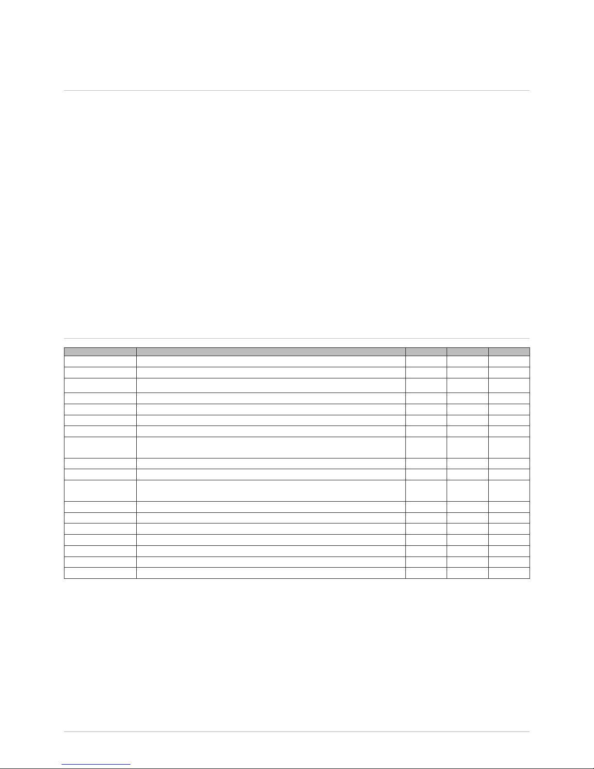
4.2 Scope of delivery
Name
Buffer vessel 1
Cover 1
Options:
- Connection set recirculation line set 100020184
4.3 Placement
The device:
• Installinalocationprotectedfromfreezingtemperatures
• Placeonaconcretepadtomakeiteasiertocleanthespace
• Installascloseaspossibletoatappointtokeepheatlossinthepipes
to a minimum.
4.4 Main dimensions – Connections
A mm B mm C mm D mm E mm F mm G mm H mm I mm
HFS 600 W 100 237 383 495 609 875 1000 1755 1090
HFS 750 W 100 237 596 708 822 1088 1000 1970 1303
J mm K mm L mm M mm N mm O mm P mm Q mm T mm
HFS 600 W 1205 1335 1348 215 350 480 848 1631 750
HFS 750 W 1418 1547 1561 231 405 646 1061 1844 750
4 Installation
a
Domestic hot water outlet R 1 1/4 (corrugated stainless
steel coil)
b
Heating boiler supply R 1 1/4
c
Heating boiler return line - with modulating heating
boiler R 1 1/4
d
Collector circuit connection - supply line 1 R 3/4
e
Fill/drain connection R 3/4
f
Heating boiler return line 2 - with modulating heating
boiler R 1 1/4
g
Cold water supply R 1 1/4 (corrugated stainless steel
coil)
h
Collector circuit return line connection R 1 1/4 heating
boiler return line (without collector circuit)
i jkImmersion sleeve Ø16 mm
l
Thermometer connection Rp 1/2
m
Manual air bleed Rp 1/2
n
Supply – collector circuit 2 R 3/4
o
Immersion sleeve Ø7 mm
Boiler dimensions
Diameter: Ø750 mm
Height HFS 600/750: 1755-1970 mm
Tilting dimension HFS 600/750: 1740/1950 mm
R = male thread
Rp = female thread

137651255 - v.01 - 23052016 HFS 650 / HSF 700
4.5 Mounting the appliance
4.5.1 Installation of a recirculation line set
To ensure that hot water is available at the taps, an inline recirculation
system can be connected to the HFS. The inline recirculation system
is not part of the boiler and must be ordered separately. Be aware that
the boiler temperature is reduced by the complete recirculation line. The
following hydraulic configurations can be used.
The recirculation set is connected to the outlet of the hot water boiler,
directly in series with the outlet or as diversion through use of a T-fitting
(depending on the flow). The hose must be inserted in the hot water outlet
over a length of at least three meters and connected to the return line
of the recirculation line and the cold water supply of the thermostatic tap
water mixing valve. A timer must be installed for the recirculation line.
See
Thermal management concept ISO publication 55.1, section 4.2.3
(1)
(7)
(9)
(10)
(8)
(6)
(2)
(3)
(5)
(4)
(10)
(11)
(7)
(9)
(8)
(6)
(1)
(2)
(3)
(5)
(4)
(10)
(7)
(9)
(8)
(1)
(6)
(2)
(3)
(5)
(4)
Recirculation connection via the cold water line
Recirculation connection via the recirculation
buffer
Recirculation connection through use of the inline
recirculation connection set (without tap water mixing valve)
4 Installation
Legend:
1) return – CH boiler
2) supply – CH boiler
3) -
4) supply – collector circuit
5) return – collector circuit
6) Domestic hot water
7) timer
8) sensor
9) domestic water pump
10) supply – cold water
11) inline recirculation line

7651255 - v.01 - 2305201614 HFS 650 / HSF 700
4.5.2 Mounting the boiler
Attention
The installation must be carried out in accordance with the current
regulations, best practices for technical work, and the instructions in
this manual.
Danger of electric shock
Solar collectors must be protected against lightning strikes and be
earthed.
Stb
WW
S2
M001070D
S2, Stb: Before proceeding with the installation the sensors must be
placed in the corresponding immersion sleeves.
See
Page 5
Stb
WW
S2
M001070D
M001071C
4 Installation

157651255 - v.01 - 23052016 HFS 650 / HSF 700
4 Installation
Fit a manual
bleed valve

7651255 - v.01 - 2305201616 HFS 650 / HSF 700
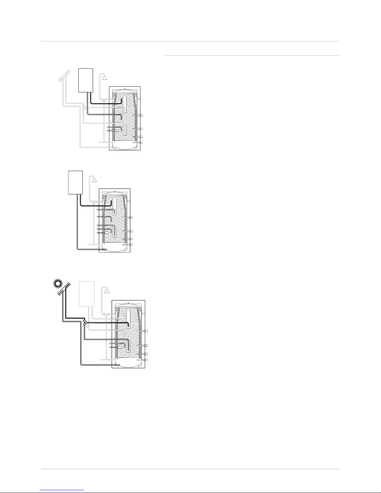
4.6 Hydraulic examples
1. Quinta Pro + HFS + DKC + collector field
4 Installation
Select diagram SC514000.SET from the SD card (see control station doc section 2.4)
The components enclosed in a green rectangle are used.
Legend CH boiler
1 CH supply
2 CH return
TB Mount boiler sensor S43.946 on boiler terminal Tdhw (see boiler doc)
Legend Quadro HFS vessel
1 Domestic hot water out R1
1
/
4
”
2 Supply – CH boiler connection R1
1
/
4
”
3 Return – CH boiler connection R1
1
/
4
”
4 Solar supply R3/4”
5 Fill R3/4”
6 2nd return – CH boiler connection R1
1
/
4
”
7 Domestic cold water in R1
1
/
4
”
8 Solar return/CH boiler return line (without collector circuit) 1
1
/
4
”
9, 10, 11 immersion sleeve Ø16 mm
12 Thermometer R1/2”
13 Manual air bleed Rp
1
/
2
” (not included)
14 2nd supply – solar connection R
3
/
4
”
15 Immersion sleeve Ø 7 mm
S2 Boiler sensor bottom – HFS vessel in no. 9
TB boiler sensor part no. S43.946 CH boiler in no. 11
Legend Solar station/collector DKC
1 Supply – solar collector
2 Return – solar collector
3 Supply to boiler
4 Return to boiler
S1 Collector sensor
S3 Primary sensor plate heat exchanger
S9 Primary sensor return
R1 Primary solar pump
R3 Secondary solar pump
See section 4.2.3 Thermal management
concept ISSO publication 55.1
#
Legionella circuit
Timer with pump for legionella prevention
(not supplied by Remeha)
$
Install domestic water portion in
accordance with the applicable domestic
water installation standards. For more
information about the recirculation
connection options, see the documentation
for the recirculation connection set.
Terminal strip RemaSOL C/2
Max. 5 kW loss
from 10 to 100 m
2
collectors

177651255 - v.01 - 23052016 HFS 650 / HSF 700
2. Quinta Pro + HFS + P-buffer + DKC + collector field
4 Installation
Select diagram SC514000.SET from the SD card (see control station doc section 2.4)
The components enclosed in a green rectangle are used.
Legend CH boiler
1 CH supply
2 CH return
TB Mount boiler sensor S43.946 on boiler terminal Tdhw (see boiler doc)
Legend Quadro HFS vessel
1 Domestic hot water out R1
1
/
4
”
2 Supply – CH boiler connection R1
1
/
4
”
3 Return – CH boiler connection R1
1
/
4
”
4 Supply – solar R3/4”
5 Fill R3/4”
6 2nd return – CH boiler connection R1
1
/
4
”
7 Domestic cold water in R1
1
/
4
”
8 Solar return/CH boiler return line (without collector circuit) 1
1
/
4
”
9, 10, 11 immersion sleeve Ø16 mm
12 Thermometer R1/2”
13 Manual air bleed Rp
1
/
2
” (not included)
14 2nd supply – solar connection R
3
/
4
”
15 Immersion sleeve Ø 7 mm
S2 Boiler sensor bottom – HFS vessel in no. 9
TB boiler sensor part no. S43.946 CH boiler in no. 11
Legend Solar station/collector DKC
1 Supply – solar collector
2 Return – solar collector
3 Supply to boiler
4 Return to boiler
S1 Collector sensor
S3 Primary sensor plate heat exchanger
S9 Primary sensor return
R1 Primary solar pump
R3 Secondary solar pump
Legend P vessel
1 Air bleed (not included) Rp ½”
2 Supply – CH installation 1/drain R1 ¼”
3 Supply – CH installation 2, R1 ¼”
4 Supply – boiler R1 ¼”
5 Immersion sleeve Ø16 mm
6 Return/supply – CH installation 3, R1 ¼”
7 Supply – boiler / buffer / heat pump
8 Supply line – collector G1”
9 Return – CH installation-2 R1 ¼”
10 Return – boiler / buffer / heat pump R1 ¼”
11 Return – low temp. system R1 ¼”
12 Return – boiler / draining
13 Return – CH system-1 / draining
14 Return line – collector
15 Thermometer connection Rp ½”
S4Slideboilersensoronvesselterminalstrip.Nearno.12
S7 Boiler sensor top in no. 5
R4 Drain pump
See section 4.2.3 Thermal management
concept ISSO publication 55.1
$
Install domestic water portion in
accordance with the applicable domestic
water installation standards. For more
information about the recirculation
connection options, see the documentation
for the recirculation connection set.
#
Legionella circuit
Timer with pump for legionella prevention
(not supplied by Remeha)
Terminal strip RemaSOL C/2
Max. 5 kW loss
Port A
Port B
From 10 to 100 m
2
collectors

7651255 - v.01 - 2305201618 HFS 650 / HSF 700
3. CWH + HFS + DKC + collector field
4 Installation
Select diagram SC514000.SET from the SD card (see control station doc section 2.4)
The components enclosed in a green rectangle are used.
Legend CH boiler
1 Domestic cold water in
2 Domestic water recirculation return
3 Domestic supply/recirculation
Legend Quadro HFS vessel
1 Domestic hot water out R1
1
/
4
”
2 Supply – CH boiler connection R1
1
/
4
”
3 Return – CH boiler connection R1
1
/
4
”
4 Supply – solar R3/4”
5 Fill R3/4”
6 2nd return – CH boiler connection R1
1
/
4
”
7 Domestic cold water in R1
1
/
4
”
8 Solar return/CH boiler return line (without collector circuit) 1
1
/
4
”
9, 10, 11 immersion sleeve Ø16 mm
12 Thermometer R1/2”
13 Manual air bleed Rp
1
/
2
” (not included)
14 2nd supply – solar connection R
3
/
4
”
15 Immersion sleeve Ø 7 mm
S2 Boiler sensor bottom – HFS vessel in no. 9
Legend Solar station/collector DKC
1 Supply – solar collector
2 Return – solar collector
3 Supply to boiler
4 Return to boiler
S1 Collector sensor
S3 Primary sensor plate heat exchanger
S9 Primary sensor return
R1 Primary solar pump
R3 Secondary solar pump
See section 4.2.3 Thermal management
concept ISSO publication 55.1
%
Install domestic water portion in
accordance with the applicable domestic
water installation standards.
Terminal strip RemaSOL C/2
Max. 5 kW loss
From 10 to 100 m
2
collectors

197651255 - v.01 - 23052016 HFS 650 / HSF 700
4. CWH + HFS + P-buffer + DKC + collector field
4 Installation
Select diagram SC514000.SET from the SD card (see control station doc section 2.4)
The components enclosed in a green rectangle are used.
Legend CWH
1 Domestic cold water in
2 Domestic water recirculation return
3 Domestic supply/recirculation
Legend Quadro HFS vessel
1 Domestic hot water out R1
1
/
4
”
2 Supply – CH boiler connection R1
1
/
4
”
3 Return – CH boiler connection R1
1
/
4
”
4 Supply – solar R3/4”
5 Fill R3/4”
6 2nd return – CH boiler connection R1
1
/
4
”
7 Domestic cold water in R1
1
/
4
”
8 Solar return/CH boiler return line (without collector circuit) 1
1
/
4
”
9, 10, 11 immersion sleeve Ø16 mm
12 Thermometer R1/2”
13 Manual air bleed Rp
1
/
2
” (not included)
14 2nd supply – solar connection R
3
/
4
”
15 Immersion sleeve Ø 7 mm
S2 Boiler sensor bottom – HFS vessel in no. 9
Legend Solar station/collector DKC
1 Supply – solar collector
2 Return – solar collector
3 Supply to boiler
4 Return to boiler
S1 Collector sensor
S3 Primary sensor plate heat exchanger
S9 Primary sensor return
R1 Primary solar pump
R3 Secondary solar pump
%
Install domestic water portion in
accordance with the applicable
domestic water installation standards.
See section 4.2.3 Thermal
management concept ISSO
publication 55.1
Terminal strip RemaSOL C/2
Max. 5 kW loss
From 10 to 100 m
2
collectors
Legend P vessel
1 Air bleed (not included) Rp ½”
2 Supply – CH installation 1/drain R1 ¼”
3 Supply – CH installation 2, R1 ¼”
4 Supply – boiler R1 ¼”
5 Immersion sleeve Ø16 mm
6 Return/supply – CH installation 3, R1 ¼”
7 Supply – boiler / buffer / heat pump
8 Supply line – collector G1”
9 Return – CH installation-2 R1 ¼”
10 Return – boiler / buffer / heat pump R1 ¼”
11 Return – low temp. system R1 ¼”
12 Return – boiler / draining
13 Return – CH system-1 / draining
14 Return line – collector
15 Thermometer connection Rp ½”
S4Slideboilersensoronvesselterminalstrip.Nearno.12
S7 Boiler sensor top in no. 5
R4 Drain pump
Port A
Port B

7651255 - v.01 - 2305201620 HFS 650 / HSF 700
5. Quinta Pro + HFS
4 Installation
Legend CH boiler
1 CH supply
2 CH return
TB Mount boiler sensor S43.946 on boiler terminal Tdhw (see boiler doc)
Legend Quadro HFS vessel
1 Domestic hot water out R1
1
/
4
”
2 Supply – CH boiler connection R1
1
/
4
”
3 Return – CH boiler connection R1
1
/
4
”
4 Supply – solar R3/4”
5 Fill R3/4”
6 2nd return – CH boiler connection R1
1
/
4
”
7 Domestic cold water in R1
1
/
4
”
8 Solar return/CH boiler return line (without collector circuit) 1
1
/
4
”
9, 10, 11 immersion sleeve Ø16 mm
12 Thermometer R1/2”
13 Manual air bleed Rp
1
/
2
” (not included)
14 2nd supply – solar connection R
3
/
4
”
15 Immersion sleeve Ø 7 mm
S2 Boiler sensor bottom – HFS vessel in no. 9
TB boiler sensor part no. S43.946 CH boiler in no. 11
Max. 5 kW loss
See section 4.2.3 Thermal
management concept ISSO
publication 55.1
Legionella circuit via boiler controller
(see boiler doc.)
#
Install domestic water portion in
accordance with the applicable
domestic water installation standards.
For more information about the
recirculation connection options,
see the documentation for the
recirculation connection set.

217651255 - v.01 - 23052016 HFS 650 / HSF 700
4.7 Connections on the domestic water side
This must be done in accordance with the current standards and local
regulations.
The maximum operating pressure of the heat exchanger in the hot water
boiler is 8 bar.
4.7.1 Special precautions
For the hydraulic connection it is absolutely essential that the supply lines
be flushed to prevent metal filings or other particles from entering the
boiler.
4.7.2 Combination inlet group
Attention
According to the safety regulations, a combination inlet group must
be installed on the cold water inlet of the domestic water heating
circuit.
Maximum pressure of the combination inlet group: 8 bar
Include the combination inlet group in the cold water circuit.
4.7.3 Shut-off valves
The primary and secondary circuits must include shut-off valves so
they can be isolated for convenient maintenance of the domestic water
heating circuit. Through use of these shut-off valves it is possible to
perform maintenance on the boiler and the components without having
to empty the entire system. Moreover, these shut-off valves make it
possible to isolate the domestic water heating circuit in the installation to
perform pressure testing at pressures higher than the permitted operating
pressure.
Attention
When connecting to copper pipes, a coupling made of steel, cast
metal or an insulating material must be used between the hot water
outlet of the boiler and this pipe to fully eliminate the possibility of
corrosion of the connection.
4.7.4 Cold water/domestic water connection
The connection to the cold water supply must be made as shown in the
diagram on page 11. A drain and a funnel for the safety fittings must be
present in the boiler room. The parts used for connection to the cold
water supply must comply with the local standards and regulations. A
combination inlet group must be installed in the cold water supply.
4.7.5 Tap water mixing valve
In combination with solar collectors, we recommend the installation of a
thermostatic tap water mixing valve.
4.7.6 Hot water recirculation line
See
Page 13.
4 Installation

7651255 - v.01 - 2305201622 HFS 650 / HSF 700
4 Installation
4.7.7 Measures to prevent backflow of heated water
A non-return valve must be installed in the cold water supply.
4.8 Connection of the expansion vessels to the collector and heating circuit
4.8.1 Boiler circuit
The expansion vessel must be connected directly to the boiler.
The installation must be carried out in accordance with the applicable
technical guidelines.
4.8.2 Collector circuit (on the boiler side)
See
Manual accompanying the solar energy station
4.9 Electrical connection
See
• Manualaccompanyingthecontrolstationforthesolarenergy
system
• Technicalmanualaccompanyingtheheatingboiler.
4.10 Commissioning
See
• Manualaccompanyingthesolarenergystations(DKC).
• Manualaccompanyingthecontrolstationforthesolarenergy
system
• Technicalmanualaccompanyingtheheatingboiler.

237651255 - v.01 - 23052016 HFS 650 / HSF 700
5 Inspection and maintenance
5 Inspection and maintenance
5.1 Switching off during the summer: Safety through Steam Back
Remeha solar installations with RemaSOL control stations include threeway protection that prevents damage to the solar energy system itself and
that potentially caused by the system (particularly when it is switched off).
See
The manual accompanying the control station.
Explanation
The installation has been designed so that no special safety
measures are required in the summer when the user will be away
for a longer period of time.
Attention
The control station may not be switched off and the heat conducting
liquid may not be drained.
The control station for the solar energy system keeps the system in
operation as long as mains electricity is available and the circulation pump
is working. With the functions for boiler protection, collector protection,
night-time cooling and complete shutdown, the system is always kept
within the desired parameters without the system entering the steam
phase. In the event of a pump failure, Steam Back also ensures that no
problems develop for the house owner when the steam temperature of
> 140 °C is reached. When a temperature of 145 °C is reached and a
pressure of approximately 2.5 bar is exceeded in the installation, one
drop of collector liquid evaporates in the collector for every two litres
of saturated vapour (steam). Within a tenth of a second the resulting
pressure increase forces the liquid out of the collector and into the
expansion vessel provided for this purpose. This all happens very quickly,
without noise and without steam pressure. The solar energy system is
now empty. There is no load on the system, because the collectors no
longer contain any collector liquid.
The collector liquid is not affected, because it is not in the collector. When
the temperature in the collector drops below 135 °C again, the two litres
of steam in each condenser condenses to one drop of collector liquid.
The collector liquid stored in the expansion vessel is released back to the
collector. The installation is filled automatically. During the next start of
the solar energy system the collector circuit is opened for three minutes.
If micro-bubbles have formed, these are now separated via the Airstop
in the station. At the end of the three minutes the installation starts
completely again. Steam Back ensures safe operation of the installation,
completely automatically, without the need for manual intervention. For a
collector surface area of 10 m2 or greater, in addition to a regular expansion
vessel a buffer vessel must be installed to provide storage capacity for
larger quantities of collector liquid. Steam Back protects all components of
the solar energy system. The solar energy station with integrated Airstop,
the special expansion vessel, the safety valve, the collectors with single pipe
and the control station for the system.
5.2 Maintenance
We recommend entering a maintenance contract that includes annual or
biannualinspectionoftheliquidlevel,anti-freezingprotectionandsystem
pressure as well as a leak check and overall check for correct operation.

7651255 - v.01 - 2305201624 HFS 650 / HSF 700
6 Commissioning report
6.1 System description
6.2 Inspection of collector circuit supply and return lines
6.3 Control station, verification of operation RemaSOL C2
Installation location ................................................................. Company name .....................................................................
Customer ................................................................................ Street .....................................................................................
Street ...................................................................................... Postal code/city .....................................................................
Postal code/city ...................................................................... Tel. ....................................... Fax ..........................................
Tel. ..................................... Fax ............................................ Mobile ....................................................................................
Mobile ..................................................................................... Email ......................................................................................
Email....................................................................................... Technician ..............................................................................
Solar energy installation for: £Domestic hot water £Supplemental heating £Swimming pool heating
Solar collectors: Type: ................................................................. Quantity: ..................................
.
Mounting type: £On the roof £Flush with the roof £Flat roof
Line: £Duo-Tube £Cu 15 £Cu 18
£Other line: ø .........................................mm Length ........................m
Insulation: ...................mm Type/Manufacturer ................................................................
Boiler: Type: ...............................................................................................
Solar energy station: £Installation integrated in the collector £Other: ............................
Solarheat-transferuid: £LS £Othersolaruid.................. Volumeinlitres:................
Installation pressure: ................................bar
Expansion vessel pre-charge
collector: ................................bar
- Return line (cold) connected Return line £OK
- Supply line (hot) connected to collector line Supply line £OK
- Sensor installed on the side where the hot collector line exits the collector (supply line) Sensor position £OK
Purging 10 min, £ OK Temperature buffer bottom S4 = .......... °C
Thenmatched-owoperation £ OK Temperature buffer top S5 = .......... °C
Collectortemperature(TC) S1 = .......... °C Temperaturecollectoreld2 S6 = .......... °C
Temperature boiler 1 bottom (TS) S2 = .......... °C Collector temperature return or S9 = .......... °C
Supply temperature exchanger (TE) S3 = .......... °C temperature buffer
6 Commissioning report

257651255 - v.01 - 23052016 HFS 650 / HSF 700
6.4 System inspection
6.5 Resetting
Commissioning
Pump primary circuit, speed-controlled R1
□
Yes□No
Three-way diverting valve R2
□
Yes□No
Pump secondary circuit, speed-controlled R3
□
Yes□No
Pump biomass boiler R4
□
Yes□No
Switchingvalvellinganddraining R5
□
Yes□No
Drain pump / swimming pool pump R8
□
Yes□No
Filling pump for the boiler R9
□
Yes□No
Legionella prevention pump R10
□
Yes□No
Heat capacity = .............. kW
∆ Ttarget = .............. K
Min. switching point = .............. °C
Collector temperature max. = .............. °C
Self-calibration phase tu = .............. min.
Minimum speed R1 = .............. rpm
Minimum speed R3 = .............. rpm
Domestic water heating, desired values of the
supplemental heating:
- Boiler circuit .............. °C
Components on the roof:
All mounting screws tightened £ yes
All plumbing connections checked, no leaks £ yes
Solar energy station:
Correctly connected to the supply and return lines £ yes
Thermometer supply and return temperature placed and checked £ yes
Boiler:
Combination inlet group installed £ yes
Pressure reducer set at ........ bar £ yes
Hot water mixer with thermosiphon U connected to the solar boiler £ yes
Thermostatic mixer set to ..............°C £ yes
Insulation on the boiler checked £ yes
All connections lines installed £ yes
Expansion vessel:
Pre-charge pressure of the expansion vessel checked £ yes
.....................................................................................................................................................................................................................................
.....................................................................................................................................................................................................................................
.....................................................................................................................................................................................................................................
.....................................................................................................................................................................................................................................
.....................................................................................................................................................................................................................................
.....................................................................................................................................................................................................................................
.....................................................................................................................................................................................................................................
.....................................................................................................................................................................................................................................
Installation manuals (solar collector, boiler, complete station, controller) given to the customer £ yes
Operation of the solar energy system via the display on the control station explained to the customer £ yes
6 Commissioning report

7651255 - v.01 - 2305201626 HFS 650 / HSF 700
6 Commissioning report
6.6 Remarks
.....................................................................................................................................................................................................................................
.....................................................................................................................................................................................................................................
.....................................................................................................................................................................................................................................
.....................................................................................................................................................................................................................................
.....................................................................................................................................................................................................................................
.....................................................................................................................................................................................................................................
.....................................................................................................................................................................................................................................
Place: .......................................................................................... Date: .............................................................................
Customer’s signature Technician’s signature

277651255 - v.01 - 23052016 HFS 650 / HSF 700
7 Maintenance report
7 Maintenance report
Maintenance number: .........................................
System description
Inspection
Three-way diverting valve R3
Temporary inlet heat regulation S10 = .............. °C
Temporary outlet heat regulation S11 = .............. °C
Pump primary circuit, speed-controlled R1
□
Yes□No
Three-way diverting valve R2
□
Yes□No
Pump secondary circuit, speedcontrolled
R3
□
Yes□No
Pump biomass boiler R4
□
Yes□No
Switchingvalvellinganddraining R5
□
Yes□No
Drain pump / swimming pool pump R8
□
Yes□No
Filling pump for the boiler R9
□
Yes□No
Legionella prevention pump R10
□
Yes□No
Installation pressure checked .......................... bar pH value ......................
Pre-charge pressure of the collector
expansion vessel .......................... bar
Freezeprotectionchecked ..........................°C
Noleaks: Visualinspection:
Collector £ OK £ OK
Pipe £ OK £ OK
Solar energy station £ OK £ OK
Domestic water heating £ OK £ OK
Controlstation Vericationofoperation £ OK
Collector temperature (TC) S1 = ............°C
Temperature boiler 1 bottom (TS) S2 = ............°C
Exchanger supply temperature (TE) S3 = ............°C
Temperature boiler 1 top S4 = ............°C
Temperature buffer bottom S4 = ............°C
Temperature buffer top S5 = ............°C
Temperaturecollectoreld2 S6=............°C
Collector temperature return or S9 = ............°C
temperature buffer
Enamelledboiler: Sacricialanodechecked £issufcient £ must be replaced
Thermostatic tap water mixer Setting ...............°C
Customer ................................................................................ Company name .....................................................................
Street ...................................................................................... Street .....................................................................................
Postal code/city ...................................................................... Postal code/city .....................................................................
Tel. ...................................... Fax ........................................... Tel. ....................................... Fax ...........................................
Mobile .................................................................................... Mobile .....................................................................................
Email....................................................................................... Email .....................................................................................
Technician ..............................................................................
Solar energy installation for: £ Domestic hot water £ Supplemental heating £ Swimming pool heating
Solar collectors: ................................................... Surface area .................................m
2
Domestic water heating: .............................................. Solar energy station: . ..............................................................

7651255 - v.01 - 2305201628 HFS 650 / HSF 700
7 Maintenance report
Complete installation checked
Functional inspection £ OK £ must be replaced
Swimming pool = ............°C Biomass = ............°C
Min. temp. Sp. = ............°C Min. temp. boiler = ............°C
Max. temp. Schw. = ............°C Max. temp. Sp. = ............°C
ΔTin =............°C ΔTin =............°C
ΔTuit =............°C ΔTuit =............°C
Place: ......................................................................... Date: ...............................................................
Customer’s signature Technician’s signature
£ Installation OK
£Installationhasdeciencies
.......................................................................................................................................................................................................
.......................................................................................................................................................................................................
.......................................................................................................................................................................................................
.......................................................................................................................................................................................................
.......................................................................................................................................................................................................
.......................................................................................................................................................................................................
.......................................................................................................................................................................................................
.......................................................................................................................................................................................................
.......................................................................................................................................................................................................
.......................................................................................................................................................................................................
.......................................................................................................................................................................................................
.......................................................................................................................................................................................................
.......................................................................................................................................................................................................
.......................................................................................................................................................................................................
.......................................................................................................................................................................................................
.......................................................................................................................................................................................................
.......................................................................................................................................................................................................
.......................................................................................................................................................................................................
.......................................................................................................................................................................................................
.......................................................................................................................................................................................................
.......................................................................................................................................................................................................
.......................................................................................................................................................................................................

297651255 - v.01 - 23052016 HFS 650 / HSF 700
7 Maintenance report

7651255 - v.01 - 2305201630 HFS 650 / HSF 700
7 Maintenance report

© Copyright
All technical and technological information contained in these technical instructions, as well as any drawings and technical
descriptions supplied, remain our property and shall not be multiplied without our prior consent in writing. Specifications subject
to change without notice.

7651255 - v.01 - 23052016
REMEHA BV
Kanaal Zuid 110,
NL-7332BDApeldoorn
THENETHERLANDS
Tel: +31 55 5496969
Fax: +31 55 5496496
Internet: www.remeha.nl
E-mail: remeha@remeha.com
 Loading...