

Remcor Vista Installation Manual
Installation Manual
VISTA POST-MIX CARBONATED &
NON-CARBONATED DISPENSERS
Part No. 300584000
December 13, 1989
Revised: February 16, 1994
Control Code A
THIS DOCUMENT CONTAINS IMPORTANT INFORMATION
This Manual must be read and understood before installing or operating this equipment
IMI CORNELIUS INC; 1989-94
PRINTED IN U.S.A

TABLE OF CONTENTS
GENERAL INFORMATION 1. . . . . . . . . . . . . . . . . . . . . . . . . . . . . . . . . . . . . . . . . . . . . . . . . .
GENERAL DESCRIPTION 1. . . . . . . . . . . . . . . . . . . . . . . . . . . . . . . . . . . . . . . . . . . . . .
UNIT DESCRIPTION 1. . . . . . . . . . . . . . . . . . . . . . . . . . . . . . . . . . . . . . . . . . . . . . . . . . .
THEORY OF OPERATION 2. . . . . . . . . . . . . . . . . . . . . . . . . . . . . . . . . . . . . . . . . . . . . .
INSTALLATION 9. . . . . . . . . . . . . . . . . . . . . . . . . . . . . . . . . . . . . . . . . . . . . . . . . . . . . . . . . . . .
UNPACKING AND INSPECTION 9. . . . . . . . . . . . . . . . . . . . . . . . . . . . . . . . . . . . . . . .
IDENTIFICATION OF LOOSE–SHIPPED PARTS 9. . . . . . . . . . . . . . . . . . . . . . . . . .
SELECTING LOCATION 9. . . . . . . . . . . . . . . . . . . . . . . . . . . . . . . . . . . . . . . . . . . . . . . .
INSTALLATION 10. . . . . . . . . . . . . . . . . . . . . . . . . . . . . . . . . . . . . . . . . . . . . . . . . . . . . . . .
PLACING UNIT IN OPERATING LOCATION 10. . . . . . . . . . . . . . . . . . . . . . . . . .
ROUTING DRIP TRAY DRAIN HOSE TO A PERMANENT DRAIN 10. . . . . . .
INSTALLING TRANSFORMER 11. . . . . . . . . . . . . . . . . . . . . . . . . . . . . . . . . . . . . .
INSTALLING BAFFLES, DISPENSING VALVES ON UNIT 0559 11. . . . . . . . .
CONNECTING PLAIN WATER SOURCE INLET LINE TO UNIT 11. . . . . . . . .
CONNECTING CO2 TO UNIT (UNIT WITH INTEGRAL (BUILT-IN)
CARBONATOR) 11. . . . . . . . . . . . . . . . . . . . . . . . . . . . . . . . . . . . . . . . . . . . . . . . . . .
CONNECTING SYRUP SOURCE LINES TO UNIT 12. . . . . . . . . . . . . . . . . . . . .
ADJUSTING CO2 REGULATORS 12. . . . . . . . . . . . . . . . . . . . . . . . . . . . . . . . . . . . . . . .
CARBONATOR PRIMARY CO2 REGULATOR (UNITS WITH BUILT-IN
CARBONATORS) 12. . . . . . . . . . . . . . . . . . . . . . . . . . . . . . . . . . . . . . . . . . . . . . . . . .
SYRUP PUMPS PRIMARY CO2 REGULATOR (SYSTEM USING
BAG-IN-BOX SYRUP SYSTEM) 12. . . . . . . . . . . . . . . . . . . . . . . . . . . . . . . . . . . . .
SUGAR SYRUP TANKS SECONDARY CO2 REGULATOR 13. . . . . . . . . . . . .
LOW-CALORIE (DIET) SYRUP TANK CO2 REGULATOR 13. . . . . . . . . . . . . .
ACTIVATING PLAIN WATER SYSTEM 13. . . . . . . . . . . . . . . . . . . . . . . . . . . . . . .
PREPARATION FOR OPERATION 13. . . . . . . . . . . . . . . . . . . . . . . . . . . . . . . . . . . . . . .
FILL WATER TANK AND START REFRIGERATION SYSTEM 13. . . . . . . . . . .
CONNECTING SYRUP INTO SYRUP SYSTEMS 14. . . . . . . . . . . . . . . . . . . . . .
ADJUSTING WATER-TO-SYRUP “RATIO” OF DISPENSED PRODUCT 14. .
OPERATORS INSTRUCTIONS 19. . . . . . . . . . . . . . . . . . . . . . . . . . . . . . . . . . . . . . . . . . . . . .
Page
OPERATING CONTROLS 19. . . . . . . . . . . . . . . . . . . . . . . . . . . . . . . . . . . . . . . . . . . . . .
DISPENSING VALVES 19. . . . . . . . . . . . . . . . . . . . . . . . . . . . . . . . . . . . . . . . . . . . .
DISPENSING VALVE KEY-LOCK SWITCH 19. . . . . . . . . . . . . . . . . . . . . . . . . . .
DAILY PRE–OPERATION CHECK 19. . . . . . . . . . . . . . . . . . . . . . . . . . . . . . . . . . . . . . .
CHANGE CO2 CYLINDER 19. . . . . . . . . . . . . . . . . . . . . . . . . . . . . . . . . . . . . . . . . . . . . .
CHANGE SYRUP SUPPLY 19. . . . . . . . . . . . . . . . . . . . . . . . . . . . . . . . . . . . . . . . . . . . .
CLEANING AND SANITIZING SYRUP SYSTEMS 20. . . . . . . . . . . . . . . . . . . . . . . . .
CLEANING 20. . . . . . . . . . . . . . . . . . . . . . . . . . . . . . . . . . . . . . . . . . . . . . . . . . . . . . .
SANITIZING SYRUP SYSTEMS 20. . . . . . . . . . . . . . . . . . . . . . . . . . . . . . . . . . . . .
SERVICE AND MAINTENANCE 21. . . . . . . . . . . . . . . . . . . . . . . . . . . . . . . . . . . . . . . . . . . . .
APPLICABLE CAUTIONS AND NOTES 21. . . . . . . . . . . . . . . . . . . . . . . . . . . . . . . . . .
MAINTENANCE SCHEDULE 21. . . . . . . . . . . . . . . . . . . . . . . . . . . . . . . . . . . . . . . . . . . .
RESPONSIBILITY KEY: 21. . . . . . . . . . . . . . . . . . . . . . . . . . . . . . . . . . . . . . . . . . . .
DAILY 21. . . . . . . . . . . . . . . . . . . . . . . . . . . . . . . . . . . . . . . . . . . . . . . . . . . . . . . . . . . .
i
300584000

TABLE OF CONTENTS (cont’d)
WEEKLY 21. . . . . . . . . . . . . . . . . . . . . . . . . . . . . . . . . . . . . . . . . . . . . . . . . . . . . . . . .
MONTHLY 22. . . . . . . . . . . . . . . . . . . . . . . . . . . . . . . . . . . . . . . . . . . . . . . . . . . . . . . .
THREE MONTHS 22. . . . . . . . . . . . . . . . . . . . . . . . . . . . . . . . . . . . . . . . . . . . . . . . .
YEARLY 22. . . . . . . . . . . . . . . . . . . . . . . . . . . . . . . . . . . . . . . . . . . . . . . . . . . . . . . . . .
WHEN OCCURRING 22. . . . . . . . . . . . . . . . . . . . . . . . . . . . . . . . . . . . . . . . . . . . . .
CHECK SYRUP-TO-WATER RATIO. 22. . . . . . . . . . . . . . . . . . . . . . . . . . . . . . . . . . . . .
CLEANING AND SANITIZING 22. . . . . . . . . . . . . . . . . . . . . . . . . . . . . . . . . . . . . . . . . . .
DAILY CLEANING OF UNIT 22. . . . . . . . . . . . . . . . . . . . . . . . . . . . . . . . . . . . . . . .
SANITIZING POST-MIX SYRUP SYSTEMS 22. . . . . . . . . . . . . . . . . . . . . . . . . .
CLEAN DROP–IN REFRIGERATION ASSEMBLY CONDENSER COIL 25. . . . . . .
CHECK ICE WATER BATH 25. . . . . . . . . . . . . . . . . . . . . . . . . . . . . . . . . . . . . . . . . . . . . .
CLEAN WATER TANK 26. . . . . . . . . . . . . . . . . . . . . . . . . . . . . . . . . . . . . . . . . . . . . . . . . .
CLEAN WATER STRAINER 27. . . . . . . . . . . . . . . . . . . . . . . . . . . . . . . . . . . . . . . . . . . . .
LIQUID DOUBLE CHECK VALVE 27. . . . . . . . . . . . . . . . . . . . . . . . . . . . . . . . . . . . . . . .
CO2 GAS CHECK VALVE 29. . . . . . . . . . . . . . . . . . . . . . . . . . . . . . . . . . . . . . . . . . . . . . .
TROUBLESHOOTING 35. . . . . . . . . . . . . . . . . . . . . . . . . . . . . . . . . . . . . . . . . . . . . . . . . . . . . .
TROUBLESHOOTING PRODUCT SYSTEMS 35. . . . . . . . . . . . . . . . . . . . . . . . . . . . .
ADJUSTMENT OF FLOW DISPENSING VALVE SYRUP REGULATOR DOES
NOT INCREASE TO DESIRED WATER-TO-SYRUP “RATIO”.35. . . . . . . . . . .
ADJUSTMENT OF DISPENSING VALVE SYRUP FLOW REGULATOR DOES
NOT DECREASE TO DESIRED WATER-TO-SYRUP “RATIO”.35. . . . . . . . . .
DISPENSED PRODUCT CARBONATION TOO LOW. 35. . . . . . . . . . . . . . . . . .
DISPENSED PRODUCT COMES OUT OF DISPENSING VALVE CLEAR
BUT FOAMS IN CUP. 36. . . . . . . . . . . . . . . . . . . . . . . . . . . . . . . . . . . . . . . . . . . . . .
DISPENSED PRODUCT FOAMS AS IT LEAVES DISPENSING VALVE. 36. .
ONLY CARBONATED WATER DISPENSED. 36. . . . . . . . . . . . . . . . . . . . . . . . . .
ONLY SYRUP DISPENSED 37. . . . . . . . . . . . . . . . . . . . . . . . . . . . . . . . . . . . . . . . .
NO PRODUCT DISPENSED FROM ALL DISPENSING VALVES (STEPS B,C,
AND D APPLICABLE ONLY TO UNITS 0557 AND 0559) 37. . . . . . . . . . . . . . .
NO PRODUCT DISPENSED FROM ONE DISPENSING VALVE 37. . . . . . . . .
TROUBLESHOOTING REFRIGERATION SYSTEM - ALL UNITS 37. . . . . . . . . . . .
COMPRESSOR DOES NOT OPERATE. 37. . . . . . . . . . . . . . . . . . . . . . . . . . . . .
COMPRESSOR WILL NOT STOP AFTER SUFFICIENT ICE BANK IS
PRODUCED. 38. . . . . . . . . . . . . . . . . . . . . . . . . . . . . . . . . . . . . . . . . . . . . . . . . . . . .
COMPRESSOR OPERATES CONTINUOUSLY BUT DOES NOT FORM
SUFFICIENT ICE BANK 38. . . . . . . . . . . . . . . . . . . . . . . . . . . . . . . . . . . . . . . . . . . .
CONDENSER FAN/AGITATOR MOTOR NOT OPERATING. 38. . . . . . . . . . . .
WARRANTY 39. . . . . . . . . . . . . . . . . . . . . . . . . . . . . . . . . . . . . . . . . . . . . . . . . . . . . . . . . . . . . .
Page
LIST OF FIGURES
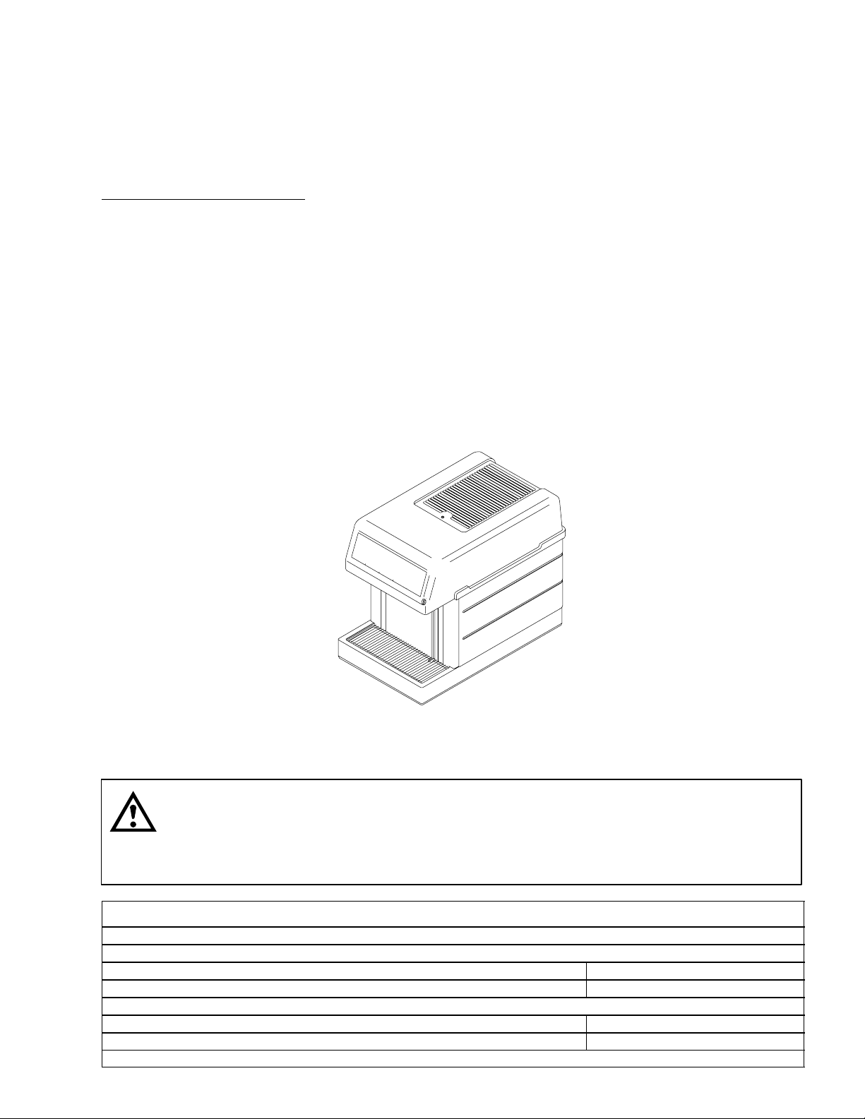
FIGURE 1. VISTA POST–MIX DISPENSER 1. . . . . . . . . . . . . . . . . . . . . . . . . . . . . . .
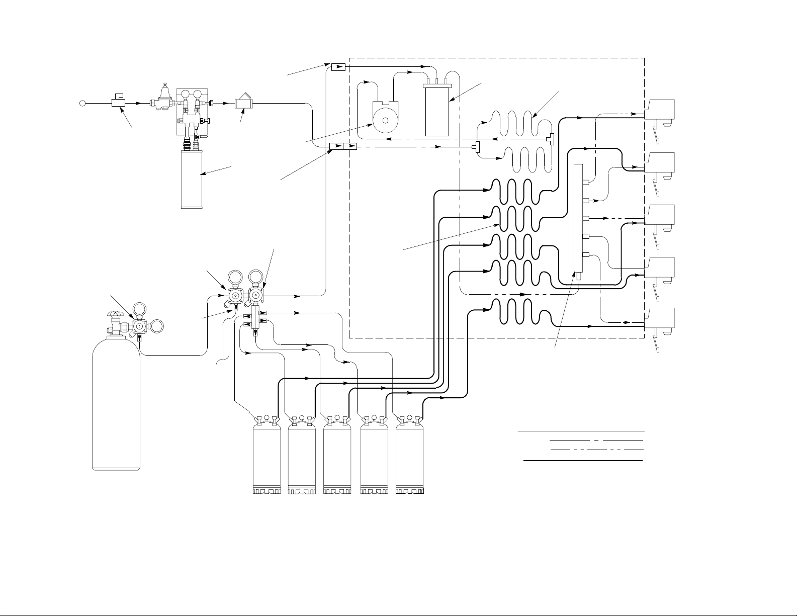
FIGURE 2. FLOW DIAGRAM (FIVE-FLAVOR CARBONATED DISPENSER) 4. .
FIGURE 3. FLOW DIAGRAM (THREE-FLAVOR CARBONATED DISPENSER) 5
FIGURE 4. FLOW DIAGRAM (FIVE-FLAVOR NON-CARBONATED DISPENSER) 6
FIGURE 5. FLOW DIAGRAM (NON-CARBONATED DISPENSER WITH
BAG-IN-BOX SYRUP SYSTEM) 7. . . . . . . . . . . . . . . . . . . . . . . . . . . . . . . . . . . . . . . . .
300584000
ii

TABLE OF CONTENTS (cont’d)
Page
LIST OF FIGURES (CONT’D)
FIGURE 6. RATIO CUP AND SYRUP DIVERSION TUBE ASSEMBLY 15. . . . . . . .
FIGURE 7. DISPENSER COMPONENTS (UNIT WITH BUILT-IN CARBONATOR) 16
FIGURE 8. DISPENSER COMPONENTS (UNIT WITHOUT CARBONATOR) 17. .
FIGURE 9. WATER STRAINER 27. . . . . . . . . . . . . . . . . . . . . . . . . . . . . . . . . . . . . . . . . .
FIGURE 10. LIQUID DOUBLE CHECK VALVE ASSEMBLY (ONE VALVE IS
SHOWN) 28. . . . . . . . . . . . . . . . . . . . . . . . . . . . . . . . . . . . . . . . . . . . . . . . . . . . . . . . . . . . .
FIGURE 11. CO2 GAS CHECK VALVE ASSEMBLY 30. . . . . . . . . . . . . . . . . . . . . . . .
FIGURE 12. DISPENSING VALVE WIRING DIAGRAM WITH KEY-LOCK SWITCH30
FIGURE 13. WIRING DIAGRAM (UNIT MODEL NO. 0557) 31. . . . . . . . . . . . . . . . . .
FIGURE 14. WIRING DIAGRAM (UNIT MODEL NUMBERS 0824 AND 1551) 31.
FIGURE 15. DISPENSING VALVE WIRING DIAGRAM W/KEY-LOCK SWITCH 32
FIGURE 16. WIRING DIAGRAM (UNIT MODEL NO. 0559) 32. . . . . . . . . . . . . . . . . .
FIGURE 17. WIRING DIAGRAM (DISPENSING VALVE 33. . . . . . . . . . . . . . . . . . . . .
LIST OF TABLES
TABLE 1. DESIGN DATA 1. . . . . . . . . . . . . . . . . . . . . . . . . . . . . . . . . . . . . . . . . . . . . . .
TABLE 2. LOOSE-SHIPPED PARTS 9. . . . . . . . . . . . . . . . . . . . . . . . . . . . . . . . . . . . .
iii
300584000
GENERAL INFORMATION
IMPORTANT: To the user of this manual – This manual is a guide for installing, operating and
maintaining this equipment. Refer to Table of Contents for page location of detailed information
pertaining to questions that arise during installation, operation, service and maintenance, or
troubleshooting this equipment.
GENERAL DESCRIPTION
This section provides a description, design data, and theory of operation for the Vista Three and Five-Flavor
Post-Mix Dispensers (with electric dispensing valves) hereinafter referred to as Units.
UNIT DESCRIPTION
The Unit is compact with a high-impact and corrosion-resistant moulded lower housing. It may be installed on a
front or rear counter, or island-mounted. The Unit refrigeration assembly is a ‘‘drop-in’’ type of 1/25 H.P. (40
watt) which can be removed for cleaning and service. The Unit, (except for the non-carbonated version), is
equipped with an integral (built-in) cold carbonator which supplies cold carbonated water to the dispensing
valves.Installation consists of locating the Unit, connecting water, CO2 and syrup lines, filling the water tank and
applying electrical power.
Optional four-inch-high legs are available to elevate the Unit above the countertop for ease of cleaning. Order
four each of the leg (P/N 314744000).
FIGURE 1. VISTA POST–MIX DISPENSER
CAUTION: Before shipping, storing, or relocating this Unit, the syrup systems must be
sanitized and all sanitizing solution must be purged from the syrup systems. All water must
also be purged from the plain and carbonated water systems. A freezing ambient
environment will cause residual water in the Unit to freeze resulting in damage to internal
components.
Table 1. Design Data
Model No.
115 VAC, 60 HZ:
Five-Flavor Carbonated 0557
Five-Flavor Non-Carbonated 0559
230 VAC, 50 HZ:
Five-Flavor Carbonated 0824
Three-Flavor Carbonated 1551
1 300584000
Table 1. Design Data (cont’d)
Overall Dimensions:
Width 13-inches
Depth 22-inches
Height 19-inches
Weights: (approximate)
Shipping 55 pounds
Dry Weight 46 pounds
Ice Bank 16 pounds
Drop-in Refrigeration Ass’y 36 pounds
Dispensing Rates:
9-oz. @ 2 per min. *100
12-oz. @ 3 per min. *55
*Number of drinks dispensed 42° F or below at 75° F syrup and plain water inlet temperature at 75° F
ambient.
Refrigerant:
Refrigerant Requirement See Unit
Nameplate
Ambient Operating Temperature 40° F to 90° F
Electrical Requirements:
Operating Voltage (115VAC Unit) 115VAC,60 Hz
Current Draw 2.6 Amps
Operating Voltage (230VAC Unit) 230VAC,50HZ
Current Draw 1.3 Amps
Inlet CO2 Requirements:
Inlet CO2 pressure must be higher than inlet water pressure, but must not exceed 60 psi.
Water Inlet Requirements:
Minimum: 25-psi Maximum: 50-psi**
**If inlet pressure exceeds maximum, a water pressure regulator is required.
WARNING: CO2 displaces oxygen. Strict attention must be observed in the prevention of
CO2 (carbon dioxide) gas leaks in the entire CO2 and soft drink system. If a CO2 gas leak is
suspected, particularly in a small area, immediately ventilate the contaminated area before
attempting to repair the leak. Personnel exposed to high concentration of CO2 gas will experience
tremors which are followed rapidly by loss of consciousness and suffocation.
THEORY OF OPERATION
Units with model numbers 0557, 0824, and 1551 dispense carbonated drinks and are equipped with integral
(built-in) carbonators. Model number 0559 dispenses non-carbonated (still) drinks and has no provision for carbonation.
2300584000

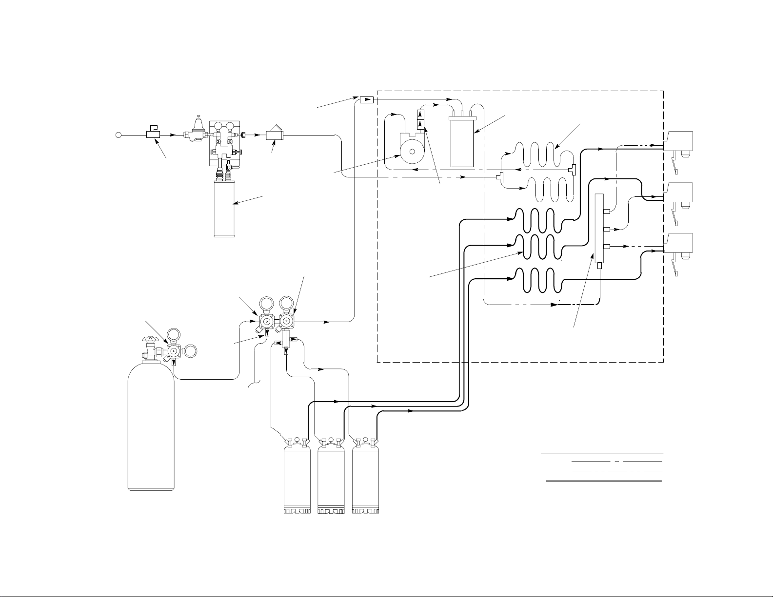
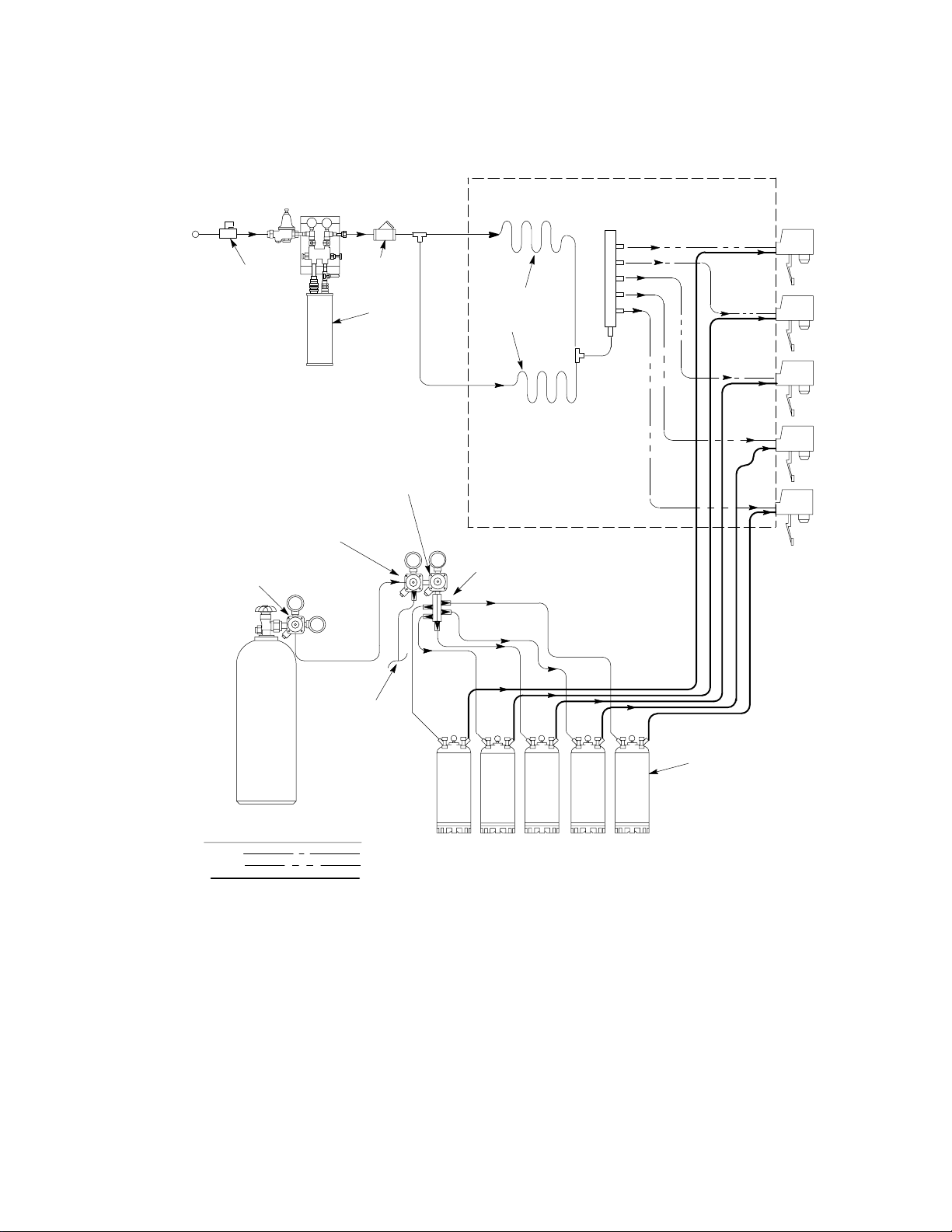
Units With Integral (Built-In) Carbonators. (see Figures 2 and 3)
Units with integral (built-in) carbonators use regulated carbon dioxide (CO
syrup tanks and CO
gas to the carbonator within the Unit. Plain cooled water pumped into the carbonator tank
2
gas to provide pressurization for the
2)
absorbs the CO2 gas and is thereby carbonated. When a drink dispense valve is opened, CO2 pressure within
the carbonator drives pre-cooled carbonated water from the carbonator to the dispensing valve. CO2 pressure
exerted upon the syrup tank contents similarly drives syrup from the syrup tank, through an individual syrup
cooling coil in the water tank, then to the dispensing valve. Carbonated water and syrup meet simultaneously at
the dispensing valve to create a carbonated drink flowing from the valve.
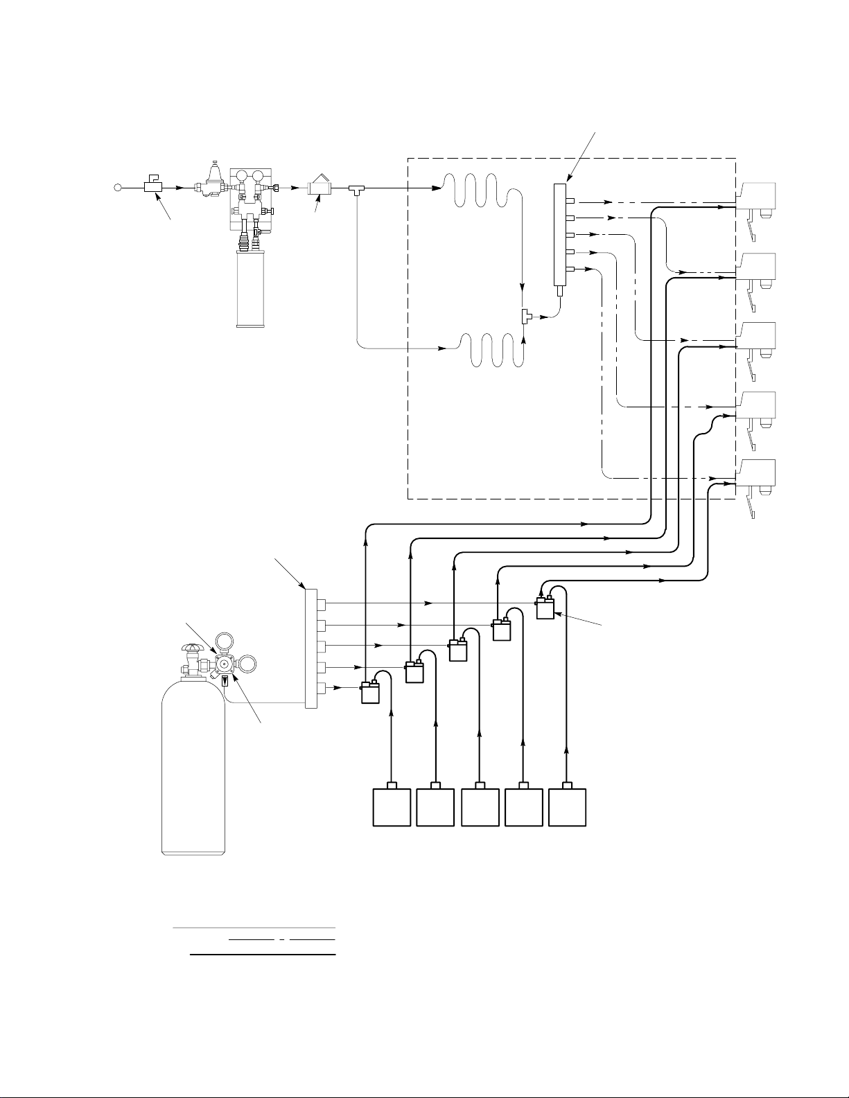
Unit without Carbonator. (see Figure 4)
When the dispensing valve is opened, inlet water at a pressure above 25-psi flows through two plain water cooling coils to the dispensing valve. At the same time, syrup under CO2 pressure in the syrup tank flows
directly to the dispensing valve. Water and syrup meet at the dispensing valve to create a non-carbonated drink
flowing from the valve. If a Bag-in-Box (BIB) configuration is used as shown in Figure 5, the flow of water remains as described, but each BIB is provided with a CO2 operated syrup pump which is energized when the
dispensing valve is operated. The syrup pump provides syrup under pressure to the dispensing valve.
3 300584000
300584000
4
WATER FILTER INSTALLATION
FOR FILTERS WITHOUT
BUILT–IN WATER SHUTOFF VALVE
WATER
SOURCE
SHUTOFF
VALVE
PRIMARY CO2
REGULATOR ASS’Y
DIET SYRUP TANK
SECONDARY CO
REGULATOR
CO
GAS
2
CHECK VALVE
WATER
STRAINER
WATER
PUMP
FILTER
DOUBLE LIQUID
CHECK VALVE ASS’Y
SYRUP TANK
SECONDARY CO
REGULATOR
2
CARBONATED
WATER TANK
PLAIN WATER
COOLING COILS
1
2
3
2
SYRUP
COOLING
COIL (5)
4
CO2 GAS
CHECK
VALVE (7)
TO DIET
SYRUP
TANK
5
DISPENSER
CARBONATED
WATER
MANIFOLD
LINE LEGEND
CO2
PLAIN WATER
CARB WATER
SYRUP
FIGURE 2. FLOW DIAGRAM (FIVE-FLAVOR CARBONATED DISPENSER)
WATER FILTER INSTALLATION
FOR FILTERS WITHOUT
BUILT–IN WATER SHUTOFF VALVE
WATER
SOURCE
SHUTOFF
VALVE
DIET SYRUP TANK
SECONDARY CO
5
PRIMARY CO2
REGULATOR ASS’Y
REGULATOR
CO2 GAS
CHECK
VALVE (5)
CO2 GAS
CHECK VALVE
WATER
STRAINER
FILTER
2
WATER
PUMP
SYRUP TANK
SECONDARY CO
REGULATOR
CARBONATED
WATER TANK
DOUBLE LIQUID
CHECK VALVE ASS’Y
2
SYRUP
COOLING
COIL (3)
CARBONATED
WATER
DISPENSER
MANIFOLD
PLAIN WATER
COOLING COILS
1
2
3
300584000
TO DIET
SYRUP
TANK
LINE LEGEND
CO2
PLAIN WATER
CARB WATER
SYRUP
FIGURE 3. FLOW DIAGRAM (THREE-FLAVOR CARBONATED DISPENSER)
WATER FILTER INSTALLATION
FOR FILTERS WITHOUT
BUILT–IN WATER SHUTOFF VALVE
WATER
SOURCE
SHUTOFF
VALVE
WATER
STRAINER
FILTER
PLAIN WATER
COOLING COILS
WATER
MANIFOLD
1
2
3
PRIMARY CO2
REGULATOR ASS’Y
LINE LEGEND
CO2
PLAIN WATER
CARB WATER
SYRUP
SYRUP TANK
SECONDARY CO
REGULATOR
DIET SYRUP TANK
SECONDARY CO
REGULATOR
TO DIET
SYRUP TANK
4
2
5
DISPENSER
2
CO2 GAS
CHECK VALVE
SYRUP
TANKS (5)
54321
FIGURE 4. FLOW DIAGRAM (FIVE-FLAVOR NON-CARBONATED DISPENSER)
6300584000
WATER
SOURCE
WATER FILTER INSTALLATION
FOR FILTERS WITHOUT
BUILT–IN WATER SHUTOFF VALVE
SHUTOFF
VALVE
WATER
STRAINER
PLAIN WATER
COOLING COILS
WATER
MANIFOLD
1
2
PRIMARY REGULATOR
(70–80 PSI)
FILTER
CO2 MANIFOLD
CHECK
VALVE
3
4
5
DISPENSER
SYRUP PUMP (5)
BAG–IN–BOX SYRUP CONTAINERS
LINE LEGEND
CO2
PLAIN WATER
SYRUP
FIGURE 5. FLOW DIAGRAM (NON-CARBONATED DISPENSER WITH BAG-IN-BOX SYRUP SYSTEM)
7 300584000

THIS PAGE LEFT BLANK INTENTIONALLY
8300584000
INSTALLATION
UNPACKING AND INSPECTION
Each Unit is completely tested under operating conditions and thoroughly inspected before shipment. At time of
shipment, the carrier accepts the Unit and any claim for damage in transit must be made with the carrier. Upon
receiving Units from the delivering carrier, carefully inspect the carton for visible indication of damage. Any
damage or irregularities should be noted at this time (not later than 15-days from date of delivery) and
immediately reported to the delivering carrier. Request a written inspection report from the carrier’s claims
inspector to substantiate claim. File claim with the delivering carrier not with IMI Cornelius Inc.
Unpack the Unit as follows:
1. Cut two bands.
2. Lift carton wrap off Unit.
3. Remove hood.
4. Remove loose-shipped items from the drip tray and check each item against Table 2.
5. Carefully inspect Unit for evidence of damage. If evidence of damage is found, file a claim against the
carrier.
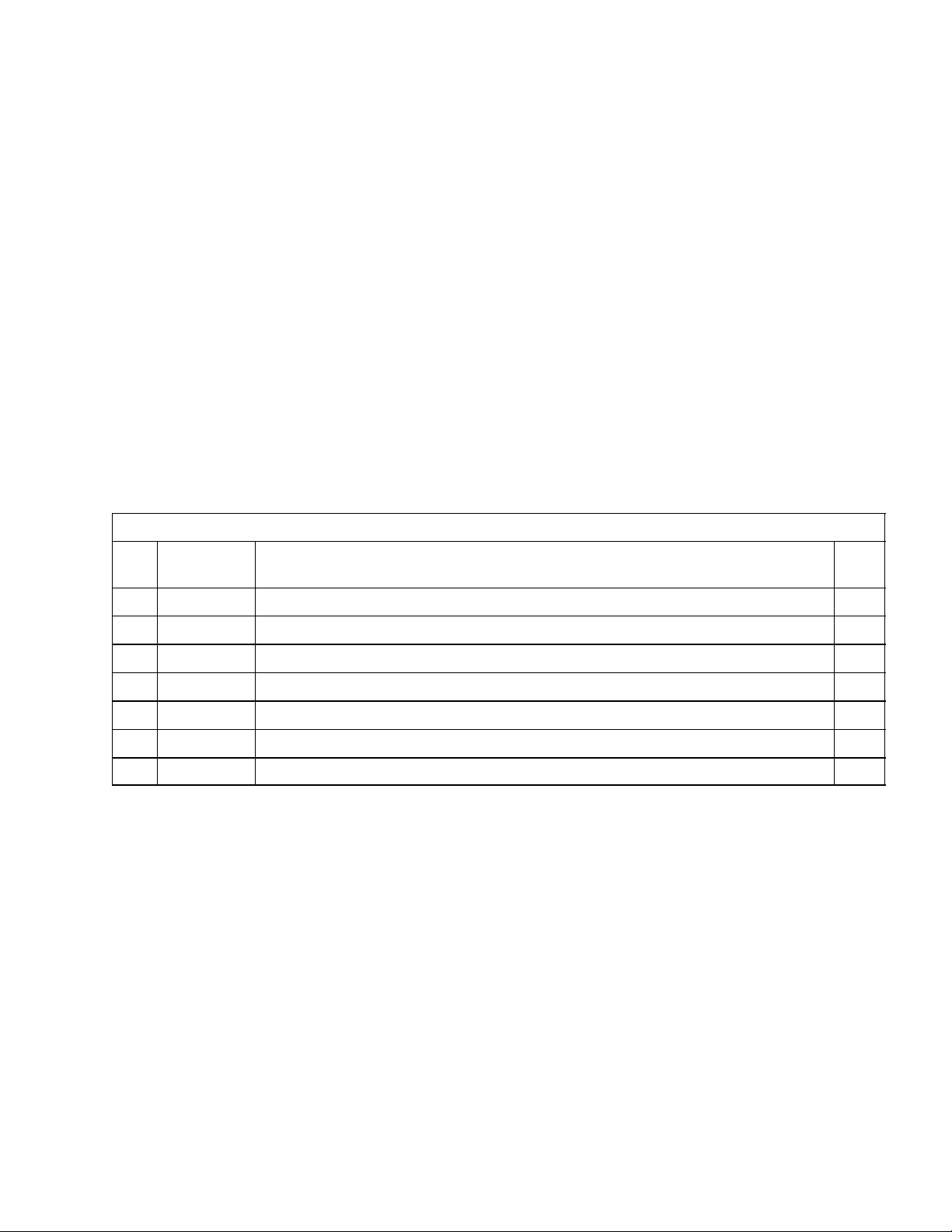
Table 2. Loose-Shipped Parts
Item
No. Part No. Name Qty.
1 317920000 Drip Tray 1
2 317982000 Cup Rest 1
3 183061 Adapter Fitting, 1/4 NPT by 7/16–20 2
4 311035000 Water Strainer 1
5 178025100 Tapered Gasket,White 2
6 319581000 Transformer Ass’y, 115VAC, 60HZ (Models 0557 and 0559) 1
7 300584000 Baffle, Dispensing Valve 5
IDENTIFICATION OF LOOSE–SHIPPED PARTS
1. Item 2 is to be installed in Drip Tray item 1.
2. ADAPTER FITTINGS ( Item 3) are to be installed in the inlet and outlet of the WATER STRAINER
(ITEM 4). The TAPERED GASKETS (ITEM 5) are used to seal connections of the water strainer to the
water inlet line.
3. TRANSFORMER ASS’Y (item 6) is used to provide electrical power to the Electric Dispensing Valves.
4. BAFFLES, DISPENSING VALVES (item 7) to be installed on dispensing valves of the Five-Flavor
Non-Carbonated Dispenser model number 0559 during installation.
SELECTING LOCATION
The Unit may be island-mounted or installed on a front or rear counter provided that the following requirements
are satisfied.
IMPORTANT: Ambient operating temperature for Unit must not exceed 90° F. Satisfactory temperatures
may be obtained using blowers, air conditioning etc. Check local codes.
9 300584000
1. Locate Unit to provide the following minimum clearance:
Over top of hood Open (15-inches)
Rear 6 inches
Sides 0 inches
WARNING: All electrical wiring must conform to national and local electrical codes.
WARNING: CO2 displaces oxygen. Strict attention must be observed in the prevention of
CO2 (carbon dioxide) gas leaks in the entire CO2 and soft drink system. If a CO2 gas leak is
suspected, particularly in a small area, immediately ventilate the contaminated area before
attempting to repair the leak. Personnel exposed to high concentration of CO2 gas will experience
tremors which are followed rapidly by loss of consciousness and suffocation.
2. Locate Unit near a grounded electrical outlet having a dedicated circuit fused at 15-amps (slow-blow) for
115 VAC, 60 HZ Units and fused at 7.5-amps for 230 VAC, 50 HZ Units. Alternate protection using an
equivalent HACR (US) circuit breaker may be used. Note: No other equipment should be connected to
this circuit.
3. Locate the Unit close to a water inlet supply with pressure and flow as given in the listing of Table 1. Design
Data.
INSTALLATION
PLACING UNIT IN OPERATING LOCATION
Place the Unit in the selected operating location. When connecting plain water, CO2, and syrup lines, leave
three feet of extra tubing to allow for servicing the Unit.
1. Place Unit in operating location meeting requirements of SELECTING LOCATION.
2. To comply with National Sanitation Foundation (NSF) requirements, Unit base must be sealed to the
countertop. Proceed as follows to seal Unit base to the countertop.
Note: An alternate arrangement to avoid sealing the Unit base to the countertop would be to install the
4-inch legs (P/N 314744000) on the Unit. When ordering, order four legs.
A. Tilt Unit up to expose bottom of the base.
B. Liberally apply silastic sealant such as Dow Corning RTV 731 or equivalent on base bottom edges.
Note: Do not move Unit after positioning or seal from Unit base to countertop will be broken.
C. Lower Unit into operating position on the countertop to complete seal from Unit base to the
countertop.
D. Apply additional sealant around bottom of the Unit base. Seal must have a minimum radius of 1/2-inch
to prevent crevices and to insure a complete seal.
ROUTING DRIP TRAY DRAIN HOSE TO A PERMANENT DRAIN
Note: Drip tray drain hose routed to a waste container is not recommended due to sanitation and
cleaning problems. Connection of drain hose to a permanent drain is recommended.
1. Preferably, route drip tray drain hose and connect to a permanent drain.
10300584000
 Loading...