

Page 1
IMI CORNELIUS INC g One Cornelius Place g Anoka, MN 55303-6234
Telephone (800) 238-3600 Facsimile (763) 422-3246
Installation/Service Manual
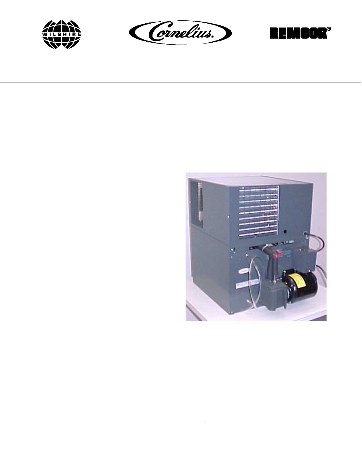
UCGR GLYCOL COOLING UNIT
Part No. 569000330
January 10, 2001
THIS DOCUMENT CONTAINS IMPORTANT INFORMATION
This Manual must be read and understood before installing or operating this equipment
PRINTED IN U.S.A
Page 2

TABLE OF CONTENTS
SAFETY INFORMATION 1. . . . . . . . . . . . . . . . . . . . . . . . . . . . . . . . . . . . . . . . . . . . . . . . . . . .
RECOGNIZE SAFETY INFORMATION 1. . . . . . . . . . . . . . . . . . . . . . . . . . . . . . .
UNDERSTAND SIGNAL WORDS 1. . . . . . . . . . . . . . . . . . . . . . . . . . . . . . . . . . . .
FOLLOW SAFETY INSTRUCTIONS 1. . . . . . . . . . . . . . . . . . . . . . . . . . . . . . . . .
CO2 (CARBON DIOXIDE) WARNING 1. . . . . . . . . . . . . . . . . . . . . . . . . . . . . . . .
SHIPPING, STORING, OR RELOCATING UNIT 1. . . . . . . . . . . . . . . . . . . . . . .
GENERAL INFORMATION 3. . . . . . . . . . . . . . . . . . . . . . . . . . . . . . . . . . . . . . . . . . . . . . . . . .
GENERAL DESCRIPTION 3. . . . . . . . . . . . . . . . . . . . . . . . . . . . . . . . . . . . . . . . . . . . . .
COOLING UNIT DESCRIPTION 3. . . . . . . . . . . . . . . . . . . . . . . . . . . . . . . . . . . . . . . . .
THEORY OF OPERATION 3. . . . . . . . . . . . . . . . . . . . . . . . . . . . . . . . . . . . . . . . . . . . . .
INSTALLATION 7. . . . . . . . . . . . . . . . . . . . . . . . . . . . . . . . . . . . . . . . . . . . . . . . . . . . . . . . . . . .
UNPACKING AND INSPECTION 7. . . . . . . . . . . . . . . . . . . . . . . . . . . . . . . . . . . . . . . .
SELECTING COOLING UNIT LOCATION 7. . . . . . . . . . . . . . . . . . . . . . . . . . . . . . . . .
INSTALLING SYSTEM 8. . . . . . . . . . . . . . . . . . . . . . . . . . . . . . . . . . . . . . . . . . . . . . . . .
PLACING COOLING UNIT IN OPERATING LOCATION 8. . . . . . . . . . . . . . . . . . . .
FILLING COOLING UNIT TANK WITH FOOD GRADE PROPYLENE
GLYCOL-TYPE ANTIFREEZE 8. . . . . . . . . . . . . . . . . . . . . . . . . . . . . . . . . . . . . . . . . . .
STARTING COOLING UNIT REFRIGERATION SYSTEM 8. . . . . . . . . . . . . . . . . . .
STARTING PROPYLENE GLYCOL ANTI-FREEZE CIRCULATING SYSTEM 9. .
OPERATORS INSTRUCTIONS 11. . . . . . . . . . . . . . . . . . . . . . . . . . . . . . . . . . . . . . . . . . . . . .
Page
OPERATING CONTROL 11. . . . . . . . . . . . . . . . . . . . . . . . . . . . . . . . . . . . . . . . . . . . . . . .
GLYCOL CIRCULATING PUMP POWER SWITCH 11. . . . . . . . . . . . . . . . . . . . .
COOLING UNIT MAINTENANCE 11. . . . . . . . . . . . . . . . . . . . . . . . . . . . . . . . . . . . . . . .
CLEANING CONDENSER COIL 11. . . . . . . . . . . . . . . . . . . . . . . . . . . . . . . . . . . . .
REPLENISHING COOLING UNIT GLYCOL (COOLANT) TANK 11. . . . . . . . . .
CLEANING COOLING UNIT EXTERIOR 11. . . . . . . . . . . . . . . . . . . . . . . . . . . . .
LUBRICATION 11. . . . . . . . . . . . . . . . . . . . . . . . . . . . . . . . . . . . . . . . . . . . . . . . . . . .
SERVICE AND MAINTENANCE 13. . . . . . . . . . . . . . . . . . . . . . . . . . . . . . . . . . . . . . . . . . . . .
ADJUSTING COOLING UNIT GLYCOL (COOLANT) TEMPERATURE 13. . . . . . . .
COOLING UNIT MAINTENANCE 13. . . . . . . . . . . . . . . . . . . . . . . . . . . . . . . . . . . . . . . .
REMOVAL OF DROP-IN REFRIGERATION ASSEMBLY 13. . . . . . . . . . . . . . .
CLEANING CONDENSER COIL 13. . . . . . . . . . . . . . . . . . . . . . . . . . . . . . . . . . . . .
CLEANING COOLING UNIT EXTERIOR 14. . . . . . . . . . . . . . . . . . . . . . . . . . . . .
REPLENISHING COOLING UNIT GLYCOL (COOLANT) TANK 14. . . . . . . . . .
LUBRICATION 14. . . . . . . . . . . . . . . . . . . . . . . . . . . . . . . . . . . . . . . . . . . . . . . . . . . .
TROUBLESHOOTING 17. . . . . . . . . . . . . . . . . . . . . . . . . . . . . . . . . . . . . . . . . . . . . . . . . . . . . .
DAIRY PRODUCT IN LINES TOO WARM 17. . . . . . . . . . . . . . . . . . . . . . . . . . . . . . . . .
COMPRESSOR DOES NOT OPERATE. 17. . . . . . . . . . . . . . . . . . . . . . . . . . . . . . . . . .
COMPRESSOR WILL NOT STOP AFTER GLYCOL (COOLANT) HAS REACHED
RECOMMENDED 265° F TO 285° F TEMPERATURE. 18. . . . . . . . . . . . . . . . . . . . .
i 0622
Page 3

TABLE OF CONTENTS (cont’d)
COMPRESSOR OPERATES CONTINUOUSLY BUT DOES NOT LOWER
GLYCOL (COOLANT) TO 265° F TO 285° F. 18. . . . . . . . . . . . . . . . . . . . . . . . . . . . . .
CONDENSER FAN MOTOR NOT OPERATING. 18. . . . . . . . . . . . . . . . . . . . . . . . . . .
WARRANTY 19. . . . . . . . . . . . . . . . . . . . . . . . . . . . . . . . . . . . . . . . . . . . . . . . . . . . . . . . . . . . . .
LIST OF FIGURES
FIGURE 1. PYTHON FOR DAIRY PRODUCT COOLING 9. . . . . . . . . . . . . . . . . . .
FIGURE 2. PARTS IDENTIFICATION 15. . . . . . . . . . . . . . . . . . . . . . . . . . . . . . . . . . . .
FIGURE 3. WIRING DIAGRAM 16. . . . . . . . . . . . . . . . . . . . . . . . . . . . . . . . . . . . . . . . . .
LIST OF TABLES
TABLE 1. DESIGN DATA 3. . . . . . . . . . . . . . . . . . . . . . . . . . . . . . . . . . . . . . . . . . . . . . .
TABLE 2. LOOSE-SHIPPED PARTS 7. . . . . . . . . . . . . . . . . . . . . . . . . . . . . . . . . . . . .
Page
0622
ii
Page 4
SAFETY INFORMATION
Recognize Safety Information
This is the safety-alert symbol. When you see this
symbol on our machine or in this manual, be alert to
the potentially of personal injury.
Follow recommended precautions and safe operating
practices.
Understand Signal Words
A signal word - DANGER, WARNING, OR CAUTION
is used with the safety-alert symbol. DANGER identi-
fies the most serious hazards.
DANGER
Safety signs with signal word DANGER or WARNING
are typically near specific hazards.
General precautions are listed on CAUTION safety
signs. CAUTION also calls attention to safety messages in this manual.
WARNING
CAUTION
Follow Safety Instructions
Carefully read all safety messages in this manual and on your machine safety signs. Keep safety signs in
good condition. Replace missing or damaged safety signs. Learn how to operate the machine and how to
use the controls properly. Do not let anyone operate the machine without instructions. Keep your machine in
proper working condition. Unauthorized modifications to the machine may impair function and/or safety and
affect the machine life.
CO2 (Carbon Dioxide) Warning
CO2 Displaces Oxygen. Strict Attention must be observed in the prevention of CO2 (carbon dioxide)
gas leaks in the entire CO2 and soft drink system. If a CO2 gas leak is suspected, particularly in a
small area, immediately ventilate the contaminated area before attempting to repair the leak. Personnel exposed to high concentration of CO2 gas will experience tremors which are followed rapidly by
loss of consciousness and suffocation.
Shipping, Storing, Or Relocating Unit
CAUTION: Before shipping, storing, or relocating this Unit, the syrup systems must be sanitized and
all sanitizing solution must be purged from the syrup systems. All water must also be purged from
the plain and carbonated water systems. A freezing ambient temperature will cause residual water
remaining inside the Unit to freeze resulting in damage to internal components of the Unit.
1 0622
Page 5

THIS PAGE LEFT BLANK INTENTIONALLY
20622
Page 6

GENERAL INFORMATION
IMPORTANT: To the user of this manual - This manual is a guide for installing, operating, and
maintaining this system. Refer to Table of Contents for page location of detailed information pertaining
to questions that arise during installation, operation, service and maintenance, or troubleshooting this
Cooling Unit.
GENERAL DESCRIPTION
This section gives the description and theory of operation for the UCGR Glycol Cooling Unit (hereafter referred
to as a Cooling Unit).
COOLING UNIT DESCRIPTION
The UCGR Glycol Cooling Unit consists basically of a refrigeration system with a 1/2 horsepower compressor, a
refrigerated glycol holding tank to cool the glycol/water solution, and a glycol circulating pump to circulate cold
glycol/water solution (coolant) out and back through the dairy products system.
Table 1. Design Data
Cooling Unit Model Number 111815
Overall Dimensions:
Width 16-1/4 inches
Height 27-5/8 inches
Depth 24-1/2 inches
Weights: (approximate)
Shipping Weight 106 Pounds
Dry Weight 102 Pounds
Capacity:
Glycol Tank 10 gallons
Refrigeration System:
Refrigerant Type and Charge See Cooling Unit Nameplate
Ambient Operating Temperature 40° F to 100° F
Electrical Requirements:
Operating Voltage 115VAC, 60Hz
Operating Current 12 Amps
THEORY OF OPERATION
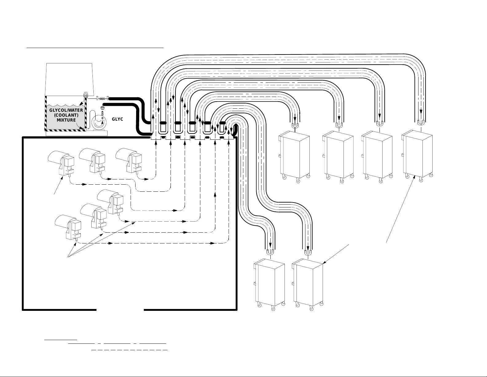
Food grade propylene glycol antifreeze/water solution (coolant) is cooled by the Cooling Unit and is circulated
through the glycol lines to each freezer. The glycol lines and the dairy product mix lines are covered with
insulation and the dairy product mix lines are kept cool by the glycol lines. Direction of glycol (coolant) flow is
from the Cooling Unit glycol tank, through glycol circulating pump, out through glycol feed line to each freezer,
and back through glycol return line to the Cooling Unit.
3 0622
Page 7
0622
NOTE: FOR GLYCOL CONNECTION DETAIL SEE FIGURE B
*COMET GLYCOL
COOLING UNIT
INSTALLED ON TOP
OF COOLER
*COMET GLYCOL
COOLING UNIT
GLYCOL/WATER
(COOLANT)
MIXTURE
BOX (SUGGESTED
INSTALLATION
GLYCOL
(COOLANT)
CIRCULATING
PUMP
4
MIX
PUMP (6)
PRODUCT LINES (6)
LINE LEGEND
GLYCOL
DAIRY PRODUCT
FREEZER (6)
Walk-In Cooler
Dairy Product Cooling System
Page 8
Ç
Ç
Ç
Ç
Ç
Ç
Ç
To Freezer
*COMET GLYCOL COOLING UNIT
INSTALLED ON TOP OF COOLER
BOX (SUGGESTED INSTALLATION
Trunk Lines to Freezers
*COMET GLYCOL
COOLING UNIT
GLYCOL/WATER
(COOLANT)
MIXTURE
5
GLYCOL
(COOLANT)
CIRCULATING
PUMP
0622
Trunk Line
Product Lines
Clamps
Elbows
Walk-In Cooler
Page 9

THIS PAGE LEFT BLANK INTENTIONALLY
60622
Page 10
INSTALLATION
UNPACKING AND INSPECTION
NOTE: The Cooling Unit was thoroughly inspected before leaving the factory and the carrier has
accepted and signed for it. Any damage or irregularities should be noted at time of delivery (or not later
than 15 days from date of delivery) and immediately reported to the delivering carrier. Request a written
inspection report from Claims Inspector to substantiate any necessary claim. File claim with the
delivering carrier, not with IMI Cornelius Inc.
1. After Cooling Unit has been unpacked, remove shipping tape and other packing material.
2. Unpack LOOSE-SHIPPED PARTS. Make sure all items are present and in good condition.
The following loose shipped parts are shipped with kit number 0576.
Table 2. Loose-Shipped Parts
Item
No. Part No. Name Qty.
1 77900200 U-Bend Fitting 6
2 77040800 Elbow Fitting 3/8 Barb 8
3 111353000 Tubing Clamp 50
4 311242000 Swivel Nut 5/8-18 2
5 176205000 Nipple for 3/8 ID Tubing 2
6 311304000 Tapered Gasket Black 2
7 174029000 Tubing Polyethylene .375 ID x .610 OD 250 ft.
8 940079000 Rubatex Insulation, 1-3/4 ID x 1/2-inch Wall 78 ft.
9 940061000 Rubatex Insulation, 1/2-inch ID x 1/4 Wall 18 ft.
10 960050000 Insulating Tape 1/8-inch x 2-inches x 50 ft. 1
11 0622 Installation Instructions 1
The product tubing, cement and tape for sheath splices, and vinyl tape will not be shipped with the unit. It must
be supplied by the parent product company. The insulation and cooling lines must be assembled by qualified
personnel only.
SELECTING COOLING UNIT LOCATION
Locate Cooling Unit so the following requirements are satisfied.
IMPORTANT: Ambient temperature for Cooling Unit must not exceed 100° F. Several means are
available to achieve proper ambient temperature and air circulation around the Cooling Unit which are
wall air intake grilles and ceiling exhaust fans, air conditioning, etc. Check local codes.
1. Cooling Unit must be installed near a properly grounded electrical outlet with proper electrical requirements
fused at 20-amps (‘‘slow-blow’’) or circuit connected through an equivalent HACR circuit breaker. No other
electrical equipment should be connected to this circuit. ALL ELECTRICAL WIRING MUST CONFORM TO
NATIONAL AND LOCAL ELECTRICAL CODES.
Note: circulating air, required to cool the refrigeration condenser coil, is drawn in through a grille on
the front and is exhausted out through grille on top of the hood. Restricting air in and out of the
Cooling Unit will decrease it’s cooling efficiency.
7 0622
Page 11
2. A minimum of 15-inches clearance must be maintained above the Cooling Unit to the nearest obstruction
(shelf, cupboard, ceiling, etc.). The front grille of the Cooling Unit must be unobstructed to allow air to enter
the hood.
INSTALLING SYSTEM
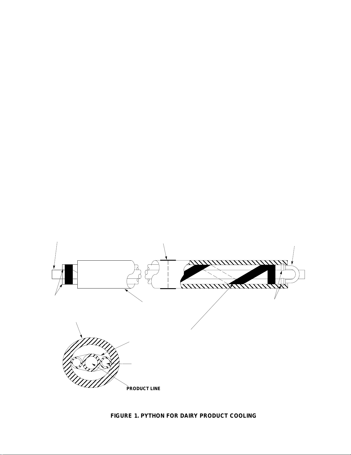
IMPORTANT: To insure maximum heat transfer and cooling of dairy product line:
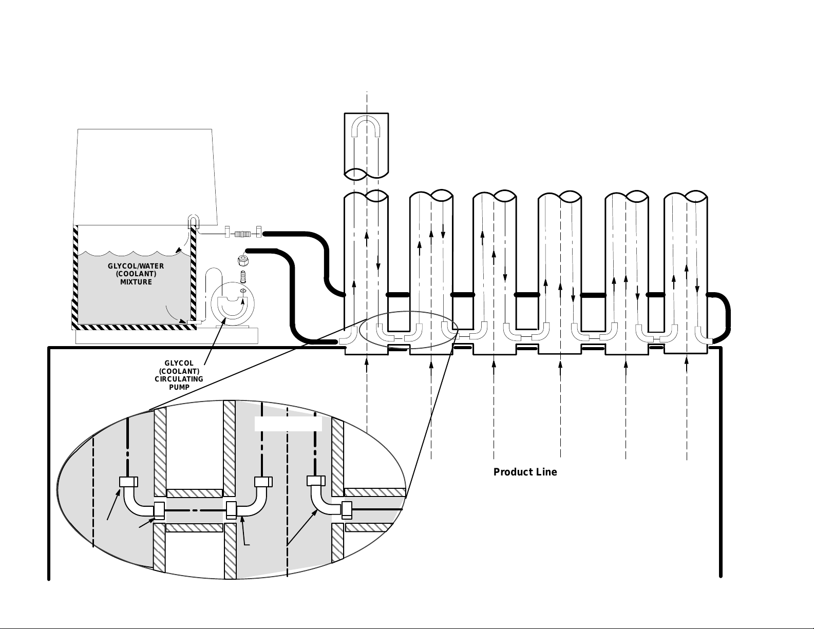
U-BEND FITTING (item 4) should be positioned as close as possible to the inlet on the freezer. The
coolant circulating lines should be held in contact with the dairy product line by spiral wrapping them
in place with vinyl tape (one turn every six to twelve inches). To meet National Sanitation Foundation
(NSF) approval, the ends of the RUBATEX INSULATION (item 8) must be taped closed around the dairy
product and coolant circulating lines. It is important that NO circulating room air come in contact with
the glycol coolant lines. Therefore the coolant truck line must be
completely sealed
PLACING COOLING UNIT IN OPERATING LOCATION
1. Place Cooling Unit in operating location meeting requirements of SELECTING COOLING UNIT
LOCATION.
2. Install SWIVEL NUT (Item 4) and NIPPLE
(item 5) on end of glycol feed line. Secure connection with TUBING CLAMP (Item 3).
3. Connect glycol feed line, with swivel nut on its end, to 3/8-flare (5/8-18) male outlet fitting on Cooling Unit
glycol circulating pump. Seal connection with TAPERED GASKET, BLACK (Item 6).
4. Connect glycol return line to barbed fitting in end of glycol return line protruding out front of Cooling Unit.
Secure connection with TUBING CLAMP (Item 3).
FILLING COOLING UNIT TANK WITH FOOD GRADE PROPYLENE
GLYCOL-TYPE ANTIFREEZE
WARNING: Use food grade propylene glycol-type anti-freeze such as Cornelius P/N
111521000 or equivalent only! Use of other than food grade propylene glycol-type
anti-freeze such as ethylene glycol (automotive) type anti-freeze in Cooling Unit glycol tank
and circulating system will create a health hazard.
1. Loosen screw securing Cooling Unit hood, then lift hood straight up to remove.
2. Remove plug from drop-in refrigeration assembly platform glycol fill hole.
3. Fill Cooling Unit tank with coolant made up of a 1 to 1 ‘‘ratio’’ of FOOD GRADE PROPYLENE
GLYCOL-TYPE ANTI-FREEZE and water solution (coolant) until coolant runs out of overflow notch in top
front corner of tank. This coolant mixture when checked with a hydrometer will read -28° F. USE
LOW-MINERAL CONTENT WATER WHERE A LOCAL WATER PROBLEM EXISTS.
MAKE SURE GLYCOL TANK IS COMPLETELY FILLED WITH COOLANT BEFORE STARTING
COOLING UNIT.
STARTING COOLING UNIT REFRIGERATION SYSTEM
WARNING: The Cooling Unit must be electrically grounded to prevent possible fatal
electrical shock or serious injury to personnel. The Cooling Unit power cord is equipped
with a three-prong plug. If a three-hole (grounded) electrical outlet is not available, use an
approved method to ground the unit.
80622
Page 12
1. Make sure glycol circulating pump power switch on side of Cooling Unit (see Figure 2) is in ‘‘OFF’’ (down)
position.
2. Plug Cooling Unit power cord into (refer to WARNING note) properly grounded electrical outlet with proper
electrical requirements. ADDITIONAL ELECTRICAL EQUIPMENT MUST NOT BE CONNECTED TO
THIS CIRCUIT.
3. Allow Cooling Unit refrigeration system to operate for two hours, then check temperature of coolant. If
coolant temperature has not dropped to 26° F to 28° F, temperature control thermostat will have to be
adjusted as instructed.
STARTING PROPYLENE GLYCOL ANTI-FREEZE CIRCULATING SYSTEM
1. Place Cooling Unit glycol circulating pump power switch (see Figure 2) in ‘‘ON’’ (up) position to start
circulating pump.
2. After insulated glycol circulating system is in operation, continue adding industrial grade propylene
glycol-type anti-freeze and water at a 1 to 1 ‘‘ratio’’ to Cooling Unit tank until coolant is at level described
when filling tank.
3. Note circulating pump for quietness of operation. A noisy pump and air bubbles in return line during
operation indicates air is being drawn into system on pump inlet side. If pump is noisy and air bubbles are
present, check pump inlet tube connection for misaligned gasket or burr on fitting. OPERATING PUMP IN
SYSTEM CONTAINING AIR BUBBLES WILL EVENTUALLY RESULT IN PUMP DAMAGE.
4. Check glycol circulating system connections for leaks and repair if evident.
5. Using INSULATING TAPE (Item 9), insulate glycol feed line connection to Cooling Unit glycol circulating
pump and glycol return line connection to Cooling Unit. FAILURE TO INSULATE LINES WILL CAUSE
LINES SWEATING, FROST ACCUMULATION AND GLYCOL TO WARM UP.
6. Install Cooling Unit hood and secure with screw.
PRODUCT TUBE
GL YCOL LINES(2)
SHEATH
CEMENT AND TAPE
SHEATH SPLICES (TYP)
RUBATEX SHEATH
(40 FT. TOT AL)
VINYL TAPE
TURNAROUND
CLAMPS
SPIRAL WRAP COOLING LINES TO PRODUCT LINE
WITH VINYL TAPE. 1 TURN EVER Y 6 TO 12 INCHES
SECTION
GL YCOL LINES (2)
PRODUCT LINE
FIGURE 1. PYTHON FOR DAIRY PRODUCT COOLING
9 0622
Page 13

THIS PAGE LEFT BLANK INTENTIONALLY
100622
Page 14

OPERATORS INSTRUCTIONS
This section covers Cooling Unit operating controls, adjustments, and Cooling Unit maintenance.
OPERATING CONTROL
GLYCOL CIRCULATING PUMP POWER SWITCH
Glycol circulating pump power switch, located on side of Cooling Unit, must be in ‘‘ON’’ (up) position before
pump will operate. Place switch in ‘‘OFF’’ (down) position to stop pump.
COOLING UNIT MAINTENANCE
CLEANING CONDENSER COIL
NOTE: Circulating air required to cool the refrigeration system condenser coil is drawn in through
grille on front and is exhausted out through grille on top of the hood. Restricting air in and out of
Cooling Unit will decrease its cooling efficiency.
The Cooling Unit hood top and front grilles must be kept free of obstructions at all times. Make sure nothing is
stored on top or in front of hood. Refrigeration condenser coil should be periodically cleaned as instructed to
maintain cooling efficiency.
REPLENISHING COOLING UNIT GLYCOL (COOLANT) TANK
The Cooling Unit tank glycol (coolant) should be periodically checked and if necessary, added to as instructed.
CLEANING COOLING UNIT EXTERIOR
The Cooling Unit exterior should be periodically cleaned as instructed.
11 0622
Page 15

THIS PAGE LEFT BLANK INTENTIONALLY
120622
Page 16
SERVICE AND MAINTENANCE
This section describes service and maintenance procedures to be performed on the Cooling Unit.
IMPORTANT: Only properly trained personnel should service Cooling Unit internal components and
electrical wiring.
WARNING: Disconnect electrical power to Cooling Unit to prevent personal injury before
attempting any internal maintenance. Only qualified personnel should service internal
components or electrical wiring.
ADJUSTING COOLING UNIT GLYCOL (COOLANT) TEMPERA TURE
NOTE: Cooling Unit tank glycol (coolant) temperature must be maintained at 26° F to 28° F for proper
cooling of dairy products lines.
1. Loosen screw securing Cooling Unit hood, then remove hood for access to control box cover.
2. Insert screwdriver through hole in control box cover and place in thermostat control slotted adjustment
screw. Turn adjustment screw to the right (clockwise) to next higher setting for a colder coolant
temperature or turn adjustment screw to the left (counterclockwise) to next lower setting for a warmer
coolant temperature.
3. Allow Cooling Unit to operate for at least two hours after adjustment. Recheck coolant temperature and
adjust thermostat control as many times as necessary until proper coolant temperature has been achieved.
4. Install Cooling Unit hood and secure with screw.
COOLING UNIT MAINTENANCE
REMOVAL OF DROP-IN REFRIGERATION ASSEMBLY
1. Unplug Cooling Unit power cord from electrical outlet.
2. Loosen screw securing Cooling Unit hood, then lift hood straight up to remove.
3. Unplug refrigeration assembly power cord from Cooling Unit power cord.
4. Remove four shipping nuts securing drop-in refrigeration assembly in lower housing.
5. Lift drop-in refrigeration assembly up and out of Lower housing.
6. Install drop-in refrigeration assembly by reversing removal procedure.
7. Plug Cooling Unit power cord into electrical outlet.
8. Install Cooling Unit hood and secure with screw.
CLEANING CONDENSER COIL
NOTE: Circulating air required to cool the refrigeration condenser coil is drawn in through grille on
front and is exhausted out through grille on top of hood. Restricting air in and out of Cooling Unit will
decrease its cooling efficiency.
IMPORTANT: Cleaning condenser coil should be performed during non-dispensing period.
13
0622
Page 17
1. Unplug Cooling Unit power cord from electrical outlet.
2. Loosen screw securing Cooling Unit hood, then remove hood.
3. Vacuum or use soft bristle brush to clean condenser coil. If available, use low-pressure compressed air.
4. Install hood on Cooling Unit and secure with screw.
5. Plug Cooling Unit power cord into electrical outlet.
CLEANING COOLING UNIT EXTERIOR
Periodically wash all external surfaces of Cooling Unit, rinse with clean water, then wipe dry with a clean soft
cloth. DO NOT USE ABRASIVE-TYPE CLEANERS.
REPLENISHING COOLING UNIT GLYCOL (COOLANT) TANK
1. Unplug Cooling Unit power cord from electrical outlet.
WARNING: Use food-grade propylene glycol-type anti-freeze such as Cornelius P/N
111521000 or equivalent only! Use of other than food grade propylene glycol-type
anti-freeze such as ethylene glycol (automotive) type anti-freeze in Cooling Unit glycol tank
and circulating system will create a health hazard.
2. Loosen screw securing Hood on Cooling Unit, then remove hood.
3. Remove plug from drop-in refrigeration assembly platform glycol fill hole.
4. Fill Cooling Unit tank with coolant made up of 1 to 1 ‘‘ratio’’ of food grade propylene glycol-type antifreeze
and water solution until coolant runs out of overflow notch in top front corner of tank. This coolant mixture
when checked with a hydrometer will read -28° F. USE LOW-MINERAL CONTENT WATER WHERE A
LOCAL WATER PROBLEM EXISTS.
MAKE SURE GLYCOL TANK IS COMPLETELY FILLED WITH COOLANT BEFORE STARTING THE
COOLING UNIT.
5. Install plug in drop-in refrigeration assembly platform glycol fill hole.
6. Install hood on Cooling Unit and secure with screw.
7. Plug Cooling Unit power cord into electrical outlet.
LUBRICATION
The Glycol circulating pump motor bearings must be oiled periodically. Refer to oiling instructions on motor. DO
NOT OVER OIL.
140622
Page 18
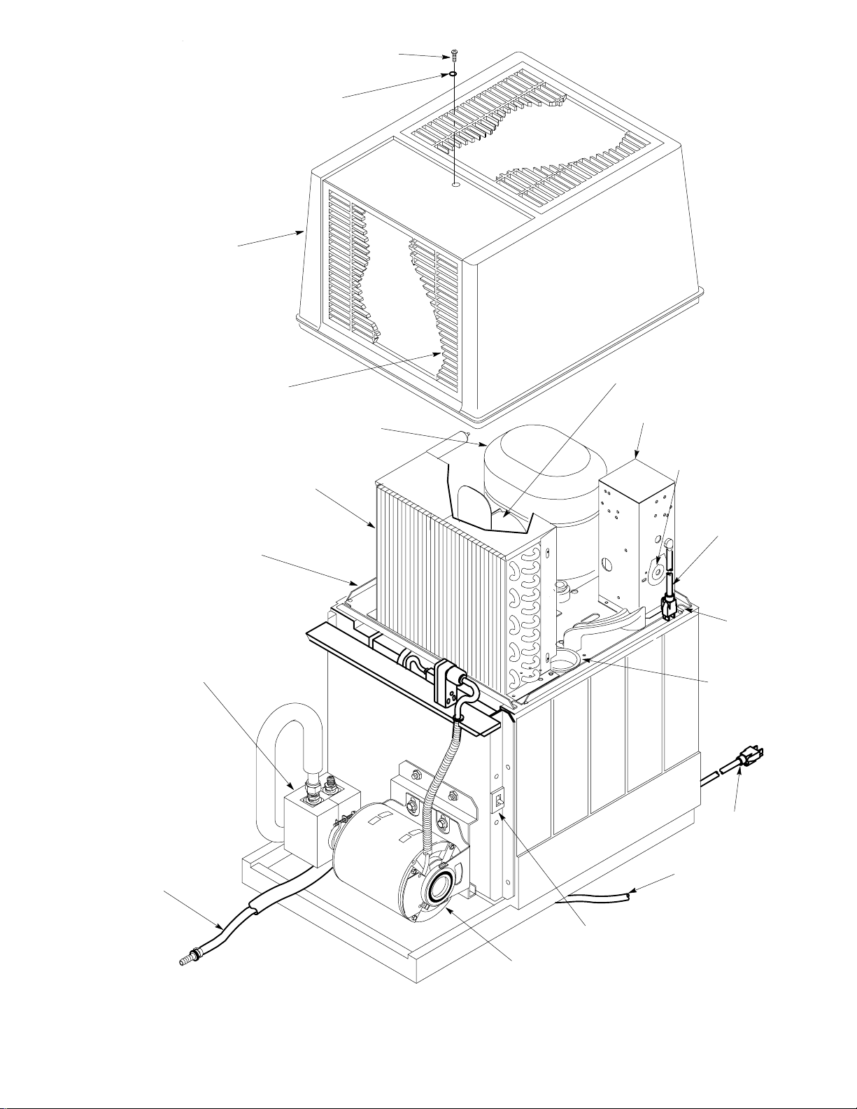
HOOD
HOOD RETAINING SCREW
O-RING
GRILLE (3)
CONDENSER COIL
DROP-IN
REFRIGERATION
ASS’Y
GLYCOL CIRCULATING
PUMP
COMPRESSOR
CONDENSER FAN MOTOR
ELECTRICAL
CONTROL BOX
THERMOSTAT
ADJUSTMENT
ACCESS HOLE
DROP-IN
REFRIGERATION
ASS’Y POWER
CORD
SHIPPING
NUTS (4)
GL YCOL FILL
HOLE PLUG
GLYCOL
RETURN
LINE
GLYCOL CIRCULATING
PUMP MOTOR
FIGURE 2. PARTS IDENTIFICATION
15
POWER
CORD
DRIP TRAY
DRAIN HOSE
CIRCULA TING PUMP
POWER SWITCH
0622
Page 19
0622
16
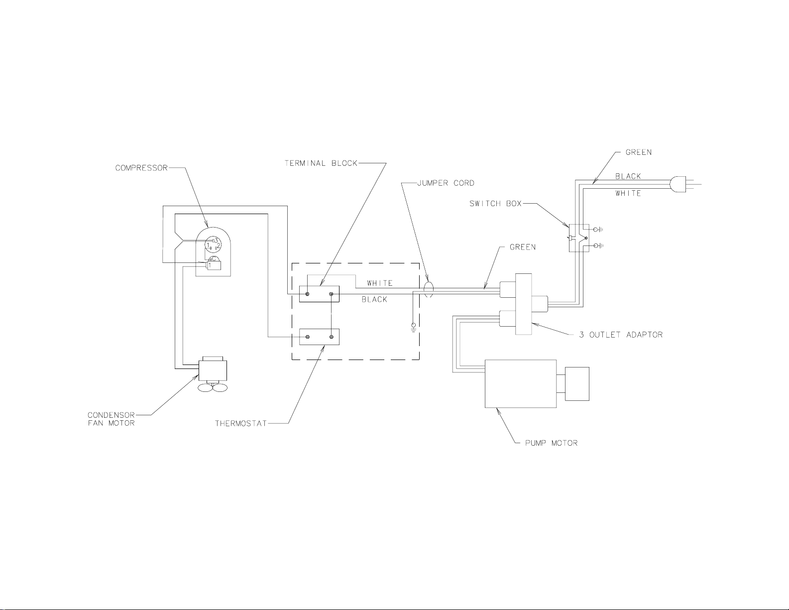
FIGURE 3. WIRING DIAGRAM
Page 20
TROUBLESHOOTING
WARNING: Disconnect electrical power from Cooling Unit to prevent personal injury
before attempting any internal maintenance. Only qualified Personnel should service
internal components or electrical wiring.
TROUBLESHOOTING DIARY PRODUCT SYSTEM
Trouble Probable Cause Remedy
DAIRY PRODUCT IN LINES
TOO WARM
TROUBLESHOOTING COOLING UNIT REFRIGERATION SYSTEM
COMPRESSOR DOES NOT
OPERATE.
A. Cooling Unit tank glycol
(coolant) too warm.
B. Cooling Unit power cord
unplugged or electrical circuit
fuse blown or circuit breaker
tripped.
C. Glycol circulating pump power
cord unplugged, switch in
‘‘OFF’’ position, or inoperable
pump or motor.
D. Inoperable Cooling Unit
refrigeration system.
A. Glycol (coolant) at
recommended 26° F to 28° F
temperature.
B. Cooling Unit power cord
unplugged.
C. No Power source (blown fuse
or tripped circuit breaker).
A. Glycol (coolant) in Cooling Unit
tank should be maintained
between 26° F to 28° F. Adjust
temperature as instructed.
B. Make sure power cord is plugged
in or circuit fuse is not blown or
circuit breaker is not tripped.
C. Make sure Power cord is plugged
in, or repair or replace pump or
motor.
D. Repair Cooling Unit refrigeration
system.
A. Refrigeration not called for.
B. Plug in Cooling Unit power cord.
C. Replace fuse or reset circuit
breaker.
D. Low voltage. D. Voltage must be at least 103 volts
at compressor terminals when
compressor is trying to start.
E. Loose, disconnected, or
broken wiring.
F. Overload protector cut out;
over-heated compressor.
Condenser fan motor not
operating as required.
G. Inoperative overload protector
or start relay.
H. Inoperative glycol tank
temperature control.
I. Inoperative compressor. I. Replace compressor.
17 0622
E. Tighten connections or replace
broken wiring.
F. Compressor will cool enough to
restart. Refer to ‘‘CONDENSER
FAN MOTOR NOT OPERATING’’
in this section.
G. Replace inoperative part.
H. Replace glycol tank temperature
control.
Page 21

Trouble RemedyProbable Cause
COMPRESSOR WILL NOT
STOP AFTER GLYCOL
A. Glycol tank temperature
control inoperative.
A. Replace glycol tank temperature
control.
(COOLANT) HAS REACHED
RECOMMENDED 26° F TO
28° F TEMPERATURE.
B. Glycol tank temperature
control stuck in closed
B. Replace glycol tank temperature
control.
position.
COMPRESSOR OPERATES
CONTINUOUSLY BUT DOES
NOT LOWER GLYCOL
(COOLANT) TO 26°F TO 28°F.
A. Cooling Unit located in
excessively hot area.
B. Air circulation through
condenser coil restricted.
A. Refer to IMPORTANT note at
start of ‘‘SELECTING
COOLING UNIT LOCATION’’ in
INSTALLATION SECTION.
B. Clean condenser coil as
instructed.
NOTE: If overload protector cuts out compressor, condenser fan motor will continue to operate;
otherwise; troubleshooting condenser fan motor problems are same as for ‘‘COMPRESSOR DOES
NOT OPERATE’’ paragraph plus the following:
CONDENSER FAN MOTOR
NOT OPERATING.
A. Jumper cord loose or
disconnected from condenser
A. Tighten connections or replace
cord.
fan motor or compressor
terminals. Broken wire in cord.
B. Fan blade obstructed. B. Remove obstruction.
C. Inoperative condenser fan
motor.
C. Replace condenser fan motor.
0622
18
Page 22

WARRANTY
IMI Cornelius Inc. warrants that all equipment and parts are free from defects in material and workmanship under normal use and service. For a copy of the warranty applicable to your Cornelius, Remcor or Wilshire product, in your country, please write, fax or telephone the IMI Cornelius office nearest you. Please provide the
equipment model number, serial number and the date of purchase.
IMI Cornelius Offices
AUSTRALIA D P.O. 210, D RIVERWOOD, D NSW 2210, AUSTRALIA D (61) 2 533 3122 D FAX (61) 2 534 2166
D AM LANGEN FELDE 32 D A-1222 D VIENNA, AUSTRIA D (43) 1 233 520 D FAX (43) 1-2335-2930
AUSTRIA
D BOSKAPELLEI 122 D B-2930 BRAASCHAAT, BELGIUM D (32) 3 664 0552 D FAX (32) 3 665 2307
BELGIUM
D RUA ITAOCARA 97 D TOMAS COELHO D RIO DE JANEIRO, BRAZIL D (55) 21 591 7150 D FAX (55) 21 593 1829
BRAZIL
ENGLAND
D TYTHING ROAD ALCESTER D WARWICKSHIRE, B49 6 EU, ENGLAND D (44) 789 763 101 D FAX (44) 789 763 644
D 71 ROUTE DE ST. DENIS D F-95170 DE UIL LA BARRE D PARIS, FRANCE D (33) 1 34 28 6200 D FAX (33) 1 34 28 6201
FRANCE
GERMANY
GREECE
HONG
ITALY
NEW
SINGAPORE
SPAIN
USA
D CARL LEVERKUS STRASSE 15 D D-4018 LANGENFELD, GERMANY D (49) 2173 7930 D FAX (49) 2173 77 438
D 488 MESSOGION AVENUE D AGIA PARASKEVI D 153 42 D ATHENS, GREECE D (30) 1 600 1073 D FAX (30) 1 601 2491
KONG D 1104 TAIKOTSUI CENTRE D 11-15 KOK CHEUNG ST D TAIKOKTSUE, HONG KONG D (852) 789 9882 D FAX (852) 391 6222
D VIA PELLIZZARI 11 D 1-20059 D VIMARCATE, ITALY D (39) 39 608 0817 D FAX (39) 39 608 0814
ZEALAND D 20 LANSFORD CRES. D P.O. BOX 19-044 AVONDALE D AUCKLAND 7, NEW ZEALAND D (64) 9 8200 357 D FAX (64) 9 8200 361
D 16 TUAS STREET D SINGAPORE 2263 D (65) 862 5542 D FAX (65) 862 5604
D POLIGONO INDUSTRAIL D RIERA DEL FONOLLAR D E-08830 SANT BOI DE LLOBREGA T D BARCELONA, SPAIN D (34) 3 640 2839 D FAX (34) 3 654 3379
D ONE CORNELIUS PLACE D ANOKA, MINNESOTA D (612) 421-6120 D FAX (612) 422-3255
LD004
4/21/98
19 0622
Page 23
IMI CORNELIUS INC.
CORPORATE HEADQUARTERS:
One Cornelius Place
Anoka, Minnesota 55303-6234
(612) 421-6120
(800) 238-3600
 Loading...