

Page 1
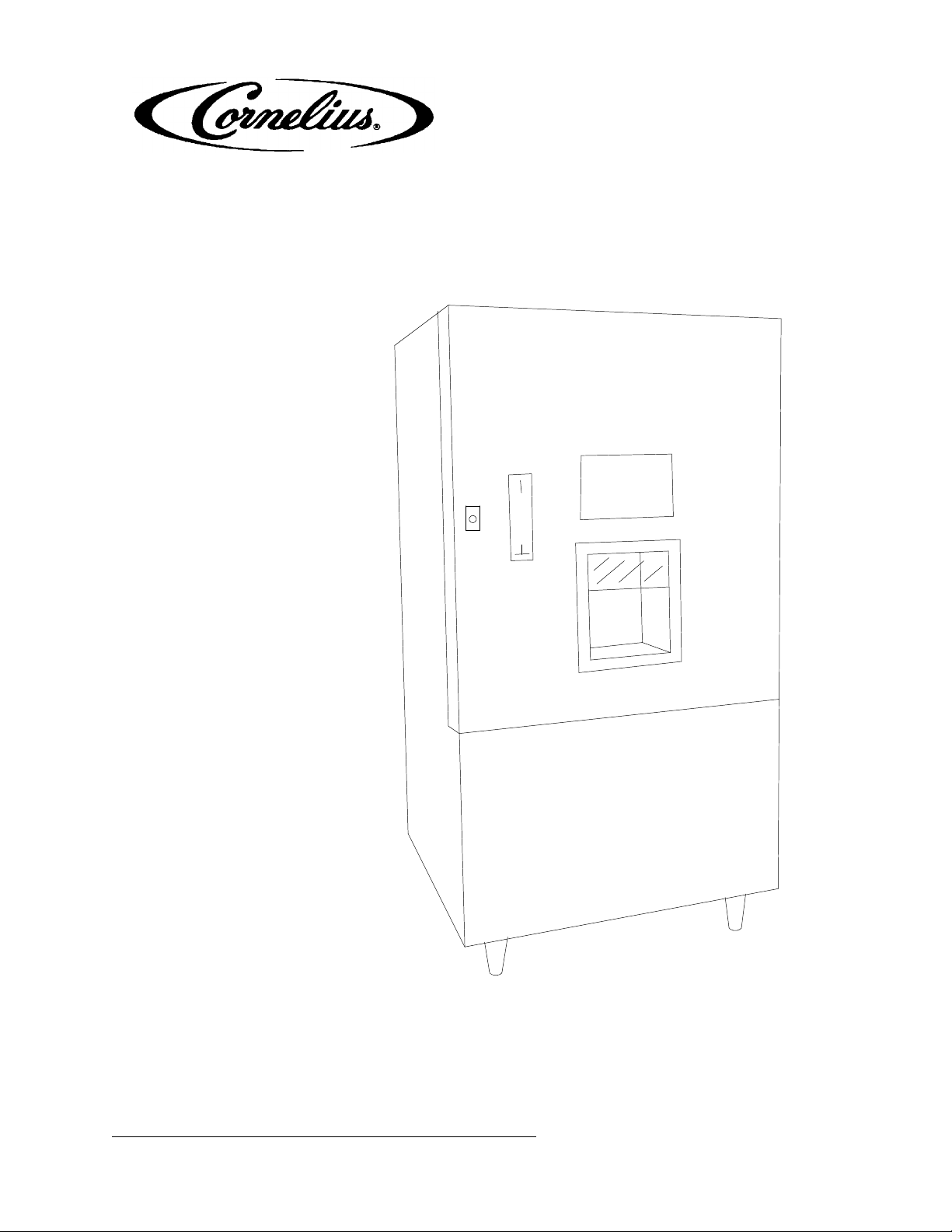
Operator’s Manual
ICE/VENDING DISPENSER
Models: TW200-V, VK, VT
REMCOR
ICE DISPENSER
Part No. 90678
February, 1997
Revision B
THIS DOCUMENT CONTAINS IMPORTANT INFORMATION
This Manual must be read and understood before installing or operating this equipment
IMI CORNELIUS INC; 1995Ó
PRINTED IN U.S.A
Page 2

TABLE OF CONTENTS
SAFETY PRECAUTIONS 1. . . . . . . . . . . . . . . . . . . . . . . . . . . . . . . . . . . . . . . . . . . . . . . . . . .
GENERAL DESCRIPTION 1. . . . . . . . . . . . . . . . . . . . . . . . . . . . . . . . . . . . . . . . . . . . . .
INSTALLA TION INSTRUCTIONS 2. . . . . . . . . . . . . . . . . . . . . . . . . . . . . . . . . . . . . . . . . . . .
UNPACKING 2. . . . . . . . . . . . . . . . . . . . . . . . . . . . . . . . . . . . . . . . . . . . . . . . . . . . . . . . . .
LEGS 2. . . . . . . . . . . . . . . . . . . . . . . . . . . . . . . . . . . . . . . . . . . . . . . . . . . . . . . . . . . . . . . .
LOCATION 2. . . . . . . . . . . . . . . . . . . . . . . . . . . . . . . . . . . . . . . . . . . . . . . . . . . . . . . . . . . .
DRAIN 2. . . . . . . . . . . . . . . . . . . . . . . . . . . . . . . . . . . . . . . . . . . . . . . . . . . . . . . . . . . . . . . .
ELECTRICAL 3. . . . . . . . . . . . . . . . . . . . . . . . . . . . . . . . . . . . . . . . . . . . . . . . . . . . . . . . .
OPERA TING INSTRUCTIONS 5. . . . . . . . . . . . . . . . . . . . . . . . . . . . . . . . . . . . . . . . . . . . . . .
PUSHBUTTON VEND MODELS 5. . . . . . . . . . . . . . . . . . . . . . . . . . . . . . . . . . . . . . . . .
PORTION SWITCH SET TO “CONTINUOUS” 5. . . . . . . . . . . . . . . . . . . . . . . . . . . .
PORTION SWITCH SET TO “TIMED” 5. . . . . . . . . . . . . . . . . . . . . . . . . . . . . . . . . . .
KEY SWITCH VEND MODELS 5. . . . . . . . . . . . . . . . . . . . . . . . . . . . . . . . . . . . . . . . . .
COIN/TOKEN VEND MODELS 5. . . . . . . . . . . . . . . . . . . . . . . . . . . . . . . . . . . . . . . . . .
POTION CONTROL SWITCH & TIMER 5. . . . . . . . . . . . . . . . . . . . . . . . . . . . . . . . . .
SERVICE SWITCH 5. . . . . . . . . . . . . . . . . . . . . . . . . . . . . . . . . . . . . . . . . . . . . . . . . . . . .
MAINTENANCE 6. . . . . . . . . . . . . . . . . . . . . . . . . . . . . . . . . . . . . . . . . . . . . . . . . . . . . . . . . . .
Page
PERIODIC CLEANING 6. . . . . . . . . . . . . . . . . . . . . . . . . . . . . . . . . . . . . . . . . . . . . . . . .
DAIL Y REQUIRE (OR AS REQUIRED) 6. . . . . . . . . . . . . . . . . . . . . . . . . . . . . . . . . .
WEEKL Y (OR AS REQUIRED) 6. . . . . . . . . . . . . . . . . . . . . . . . . . . . . . . . . . . . . . . . .
MONTHL Y 6. . . . . . . . . . . . . . . . . . . . . . . . . . . . . . . . . . . . . . . . . . . . . . . . . . . . . . . . . . .
CLEANING INSTRUCTION 7. .. .. .. .. .. .. .. .. .. .. .. .. .. .. .. .. .. .. .. .. .. .. .. ..
TROUBLESHOOTING 8. . . . . . . . . . . . . . . . . . . . . . . . . . . . . . . . . . . . . . . . . . . . . . . . . . . . . .
DISPENSER COMPLETELY INOPERATIVE 8. . . . . . . . . . . . . . . . . . . . . . . . . . . . . .
DISPENSER BLOWS FUSE OR CIRCUIT BREAKER 8. . . . . . . . . . . . . . . . . . . . . .
AGITATOR MOTOR INOPERATIVE GATE OPERATES NORMALL Y SERVICE
SWITCH DOES NOT OPERATE MOTOR. 8. . . . . . . . . . . . . . . . . . . . . . . . . . . . . . . .
GATE INOPERATIVE. AGITATOR OPERATES NORMALL Y. SERVICE SWITCH
DOES NOT OPERATE GATE. 8. . . . . . . . . . . . . . . . . . . . . . . . . . . . . . . . . . . . . . . . . . .
PUSHBUTTON OR KEY SWITCH INOPERATIVE. SERVICE SWITCH
OPERATES UNIT NORMALLY. 9. . . . . . . . . . . . . . . . . . . . . . . . . . . . . . . . . . . . . . . . . .
COIN MECHANISM INOPERATIVE. COIN RETURNS. SERVICE SWITCH
OPERATES UNIT NORMALLY (VT MODELS ONLY) 9. . . . . . . . . . . . . . . . . . . . . . .
COIN MECHANISM INOPERATIVE COIN IS ACCEPTED. SERVICE SWITCH
OPERATES UNIT NORMALLY (--VT MODELS ONL Y) 9. . . . . . . . . . . . . . . . . . . . . .
SLUSHY ICE. WATER IN HOPPER. 9. . . . . . . . . . . . . . . . . . . . . . . . . . . . . . . . . . . . . .
ICE SOLIDIFIED OR PACKED IN HOPPER. 10. . . . . . . . . . . . . . . . . . . . . . . . . . . . . .
ELECTRONIC DISPENSER CONTROL 11.. . . . . . . . . . . . . . . . . . . . . . . . . . . . . . . . . . . . .
DIP SWITCH SETTINGS 12. . . . . . . . . . . . . . . . . . . . . . . . . . . . . . . . . . . . . . . . . . . . . . . . . . . .
EDC TROUBLESHOOTING 13. . . . . . . . . . . . . . . . . . . . . . . . . . . . . . . . . . . . . . . . . . . . . . . . .
TESTING INPUT SWITCHES (TERMINAL 3--13) 13. . . . . . . . . . . . . . . . . . . . . . . . . .
TEST OUTPUT DEVICES 13. . . . . . . . . . . . . . . . . . . . . . . . . . . . . . . . . . . . . . . . . . . . . .
WARRANTY 14. . . . . . . . . . . . . . . . . . . . . . . . . . . . . . . . . . . . . . . . . . . . . . . . . . . . . . . . . . . . . .
i
90678
Page 3

TABLE OF CONTENTS (cont’d)
LIST OF FIGURES
FIGURE 1. LEG INSTALLATION 2. . . . . . . . . . . . . . . . . . . . . . . . . . . . . . . . . . . . . . . . .
FIGURE 2. DRAIN INSTALLATION 3. . . . . . . . . . . . . . . . . . . . . . . . . . . . . . . . . . . . . . .
FIGURE 3. PLUG INSTALLATION 3. . . . . . . . . . . . . . . . . . . . . . . . . . . . . . . . . . . . . . .
FIGURE 4. MODEL TW200--VK KEY VEND LOCK INSTALLATION 4. . . . . . . . . .
FIGURE 5. ELECTRONIC DISPENSER CONTROL 1 1. . . . . . . . . . . . . . . . . . . . . . . .
FIGURE 6. HOW TO CHANGE SWITCH SETTINGS 12. . . . . . . . . . . . . . . . . . . . . . .
LIST OF TABLES
TABLE 1. SPECIFICATIONS 1.. .. .. .. .. .. .. .. .. .. .. .. .. .. .. .. .. .. .. .. .. ..
Page
MFG. UNDER PATENT NOS.
3,393,839
3,517,860
CANADIAN 912,514
4,346,824 (10/72)
OTHER PATENTS PENDING
90678
ii
Page 4
SAFETY PRECAUTIONS
This ice dispenser has been specifically designed to provide protection against personal injury and eliminates
contamination of ice. To insure continued protection and sanitation, observe the following
Always disconnect power to the dispenser before servicing or cleaning.
Never place hands inside of hopper or gate area without disconnecting power to the dispenser. Agitator rotation
occurs automatically when the dispenser is energized!
ALWAYS be sure the removable lid is properly installed to prevent unauthorized access to the hopper interior and possible contamination of ice.
ALWAYS be sure the upper and lower front panels are securely fastened.
ALWAYS keep areaaround the dispenser clean of ice cubes.
CAUTION: Dispenser cannot be used with crushed or flaked ice.
Use of bagged ice which has frozen into large chunks can void warranty. The dispenser
agitator is not designed to be an ice crusher. Use of large chunks of ice which “jam up”
inside the hopper will cause failure of the agitator motor and damage to the hopper. If bagged ice
is used, it must be carefully and completely broken into small, cube-sized pieces before filing into
the dispenser hopper.
GENERAL DESCRIPTION
Remcor solves your ice service needs the sanitary, space saving, economical way. The Remcor 200 lb. ice
vending dispenser is designed for automatic filling from your existing icemaker, or a new unit of your choice.
These ice dispensers are available with several vending options to meet all your needs. Refer to page 18 for
information on icemaker installation kits and vending options accessories. All Remcor dispensers are designed
to dispense all types of cubes and cublet ice. These dispensers cannot be used with flaked ice.
Table 1. Specifications
Model: TW200--V, --VT, --VK
Ice Storage Capacity: 200 lbs.
Electrical: 115 Volts, single phase, 60 Hz.
Electrical Connection 12FT., 3-wire cord w/3-prong ground-type plug
Amperage: 6.0
Drain Connection: 3/4 FPT
Dimensions: 32? Wide x 63 5/8? high x 33? deep
Shipping Weight: 290 lbs.
Operating Weight (less icemaker) 490 lbs.
Cabinet: Neutral beige baked enamel finish with
simulated walnut vinyl clad door panel.
Accessories Installation Kits
31351 Coin Acceptor (Quarters) 01930 Sunbeam Series C--20, C--40, C--61
31352 Coin Acceptor (.900 token) 01931 Manitowac Series 200, 400
31250 Pushbutton Vend Package 01932 Kold Draft Series GT7, GT8
31252 Key Vend Package 01935 Scotsman MH--750
70467 Cash Box Lock 01936 Scotsman CM--450
1
90678
Page 5
INSTALLATION INSTRUCTIONS
UNPACKING
With the dispenser upright, carefully remove all carton material and unpack all accessories. Inspect for shipping
damage and report any such damage to the shipper immediately.
LEGS
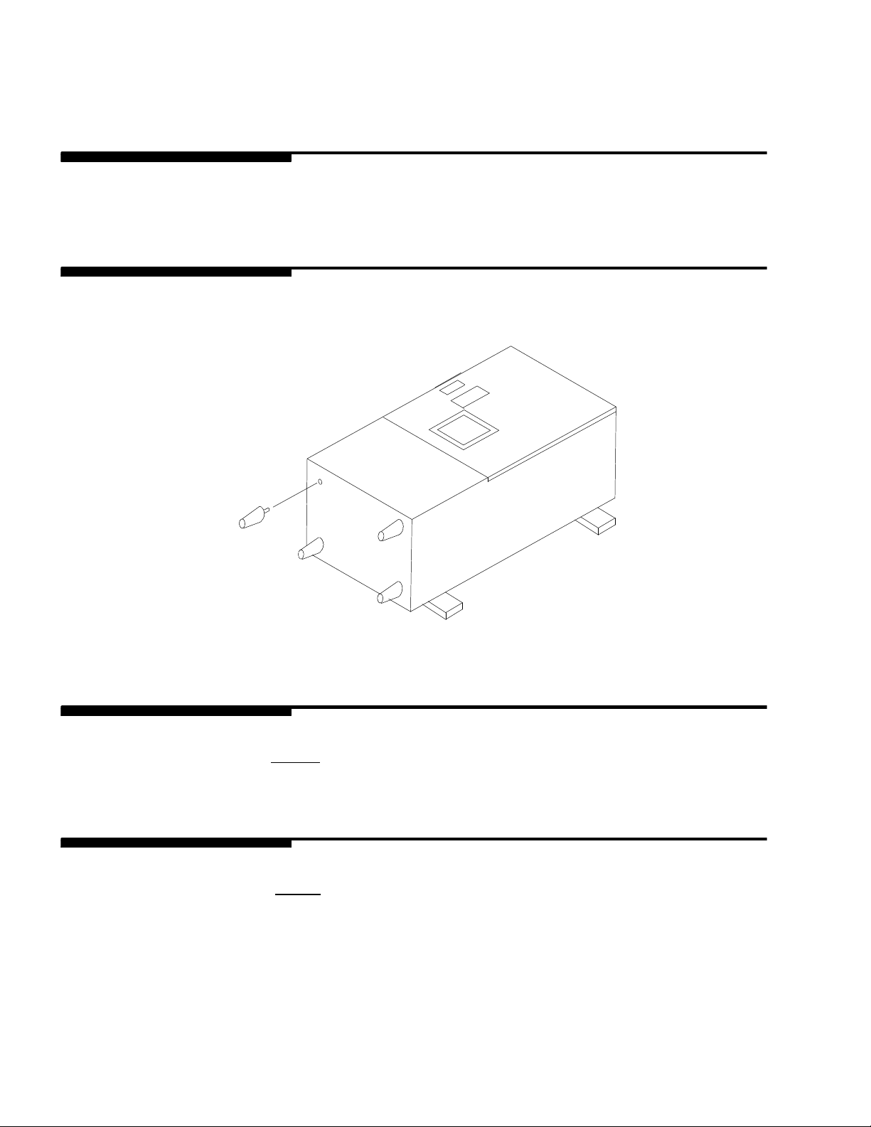
Carefully lay the dispenser on its back on two by fours, and install the four legs supplied, by securely screwing
them into the threaded sockets on the bottom of the unit. After installation of the legs, stand the unit upright.
FIGURE 1. LEG I NSTALLATION
LOCATION
Locate the dispenser in an indoor location away from hot air discharge vents. After setting in position, adjust the
legs as required to level the unit. NOTE: To ensure proper drainage, the unit must be level in all
directions.
DRAIN
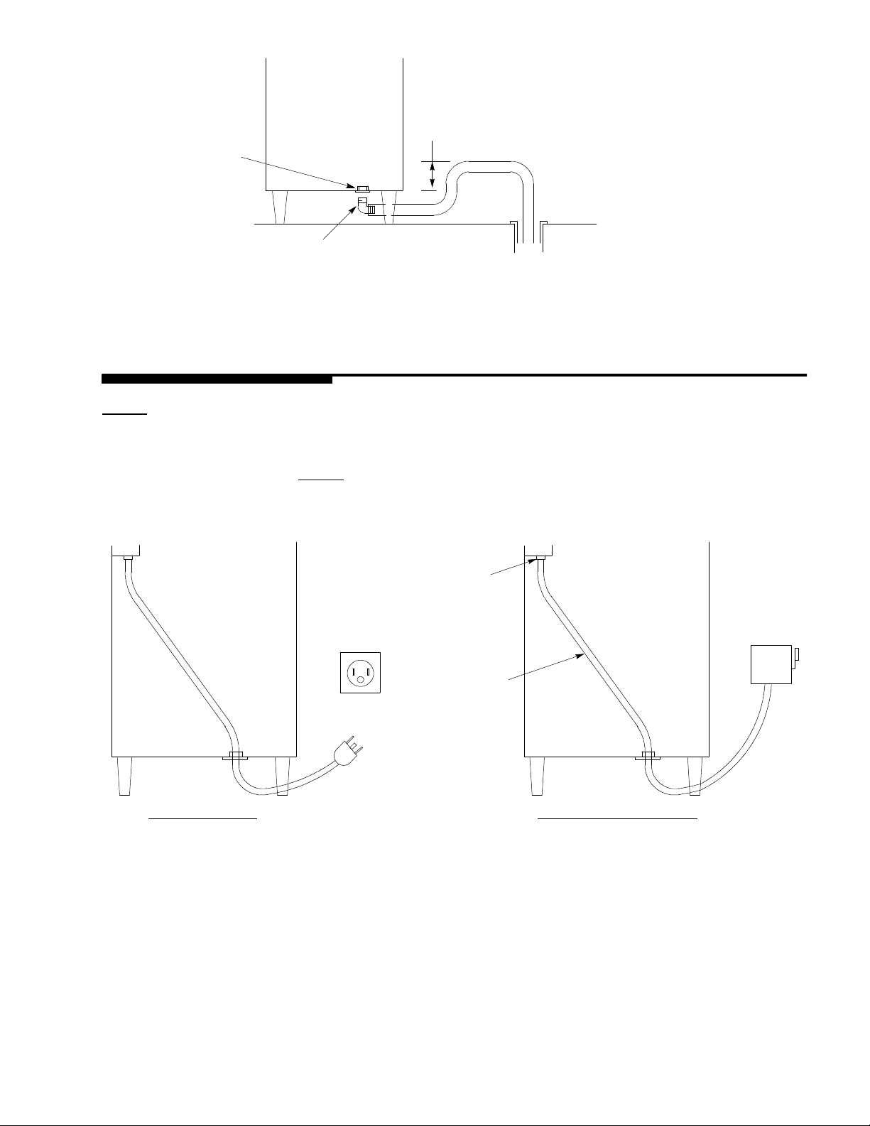
Connect the drain hose to the 3/4? FPT drain connection on the bottom of the dispenser. Run this hose to an
open gravity drain (see Figure 2). NOTE: Do not allow any part of the drain hose to rise higher than 12?
above the bottom of the cabinet, or the unit may not drain properly. Drain hose should be 3/4? I.D.
Minimum.
90678
2
Page 6
12-IN
MAX
3/4-IN FPT
DRAIN
3/4-IN FPT X 3/4-IN BARB ELBOW
FIGURE 2. DRAIN INSTALLATI ON
ELECTRICAL
NOTE: Check the unit nameplate for proper voltage. all wiring must be per N.E.C. and local electrical
codes. Route the power cord out through the bushing in the bottomof the cabinet and connect to a grounded
electric outlet. The power cord may be replaced if desired by permanent conduit. Remove the cord and strain
relief, install an appropriate conduit connector in the knockout in the electrical box, and make new electrical connections as shown in Figure 3. NOTE: Disconnect switch may be required by code in the case of perma-
nent connection.
CORD CONNECTED
CONDUIT
CONNECTOR
DISCONNECT
CONDUIT
OUTLET
PERMANENTLY CONNECTED
FIGURE 3. PLUG I NSTALLATION
3
90678
Page 7
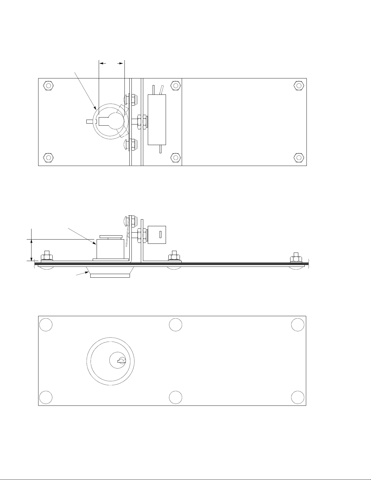
4
BY REMCOR
NUT SUPPLIED
9/16 TO 7/8
MUST HOLD
CYLINDER
CUSTOMER
SUPPLIED BY
1-IN
MUST HOLD
SPACER AS
BY CUSTOMER
REQ’D SUPPLIED
FIGURE 4. MODEL TW200--VK KEY VEND LOCK INSTALLATION
90678
Page 8

OPERATING INSTRUCTIONS
PUSHBUTTON VEND MODELS
Insert a bucket or container into the vending area and close the plastic Vend door. Ice can be dispensedby operating the pushbutton as follows:
Portion Switch Set To “Continuous”
Ice dispenses as long as vend switch is maintained. Ice flow stops when end switch is released.
Portion switch set to “Timed”
Ice flow starts when vend switch is actuated, and continues for preset portion time. Ice flow stops automatically.
A second portion may be obtained by releasing and actuating the vend switch a second time after the first vend
is completed. The vend switch has no effect during a vend.
NOTE: Dispenser will not operate with the vend door open.
KEY SWITCH VEND MODELS
Install key cylinder assembly as shown in Figure 4. Insertingthe proper key and turning will actuate the vend
switch. The unit will operate with the portion switch set in either the “continuous” or “Timed” mode describedfor
pushbutton vend models.
COIN/TOKEN VEND MODELS
Insert a bucket or container into the vending area and close the plastic vend door. Inserting the proper coin or
token into the coin slot will cause dispensingof a timed portionof ice. A second portionmay be obtained by inserting another coin after the first vend is completed. Coins inserted during a vend will be lost.
Coins will return automatically if there is no power to the dispenser and/or no ice in the hopper (light on).
The portion control switch must be in the “timed” position for operation of the portion control timing function.
POTION CONTROL SWITCH & TIMER
The portion switch selects either continuous or timed vending for pushbutton and key switch operation.
The portion may be adjusted by turning the knob, clockwise to increase, and counterclockwise to decrease.
SERVICE SWITCH
The service switch allows ice to be dispensed with the vend door removed for the purpose or checking operation, or emptying the hopper for maintenance or cleaning.
5
90678
Page 9

MAINTENANCE
The followingdispenser maintenance items should be performed at the intervals indicated:
PERIODIC CLEANING
The followingdispenser maintenance should be performed at the intervals indicated.
DAILY (or as required)
Remove foreign material from vending a rea sink to prevent drain blockage.
Empty cash box (coin operated units only).
WEEKLY (or as required)
Clean vending area and vend door.
Check for proper water drainage from the vendingarea sink.
MONTHLY
Clean and sanitize the hopper interior (see CLEANING INSTRUCTIONS).
90678
6
Page 10

CLEANING INSTRUCTION
WARNING: Disconnect power before cleaning. Do not use metal scrapers. Sharp objects or
abrasives on the plastic surfaces as damage may result. Do not use solvents or other
cleaning agents a s they may attack the plastic
1. Clean the ice dispenser interior at least once a month.
2. Remove the agitator bolt and lift off the agitation assembly taking care not to lose the shaft key. W ash and
rinse all parts thoroughly.
3. Carefully remove,wash and rinse all internal hopper components.
4. Wash down the inside of hopper and top cover with mild detergentsolution, and rinse thoroughly to remove
all traces of detergent.
5. Replace agitator and othercomponents.
6. Wash the vendingarea with a mild detergent solution and rinse thoro ughly.
7. Remove the vend door and wash and rinse thoroughly. ( To avoid scratching, do not use abrasives.)
8. Wash the vendingarea with a mild detergent solution and rinse thoro ughly.
9. Replace the vend door, checking to be sure it actuates the interlock switch properly.
7
90678
Page 11

TROUBLESHOOTING
IMPORTANT: Only qualified personnel should service internal components or electrical wiring.
WARNING: If repairs are to be made to a product system, remove quick disconnects from
the applicable product tank, then relieve the system pressure before proceeding. If repairs
are to be made to the CO2system, stop dispensing, shut off the CO2supply, then relieve the
system pressure before proceeding. If repairs are to be made to the refrigeration system, make sure
electrical power is disconnected from the unit.
Should your unit fail to operate properly, check that there is power to the unit and that the hopper contains ice. If the problem persists, check the following.
1. Determine if the agitator is rotating (check for the sound f ice movement in the hopper).
2. Observe whether the gate is operating.
3. Check if the unit dispenses when the “service switch” is operated.
After checking the above, refer to the following “troubleshooting Guide” under the appropriate symp-
tom(s) for possible problem causes and corrective action.
Contact your local syrup or beverage equipment distributor for additional information and trouble-
shooting of beverage system.
Trouble Probable Cause Remedy
DISPENSER COMPLETELY
INOPERATIVE
DISPENSER BLOWS FUSE
OR CIRCUIT BREAKER
AGITATOR MOTOR
INOPERATIVE GATE
OPERATES NORMALLY
SERVICE SWITCH DOES
NOT OPERATE MOTOR.
A. Unit unplugged. A. Connect plug to proper supply
circuit.
B. Supply circuit deenergized. B. Energize circuit.
A. Supply circuit overloaded. A. Change circuits, or remove extra
loads.
B. Defective agitator motor. B. Check motor for stuck rotor, faulty
centrifugal switch, or shorted
windings. Repair or replace if
defective.
C. Wiring shorted. C. Check all components and wiring
for short circuit. Replace faulty
components.
A. Motor protector tripped. A. Depress reset button on bottom
end of motor.
B. Defective agitator relay. B. Check relay coil and contacts.
Replace if defective.
C. Defective agitator motor. C. Check motor for stuck rotor, open
protector, faulty centrifugal switch,
shorted or open windings. Repair
or replace if defective.
GATE INOPERATIVE.
AGITATOR OPERATES
NORMALLY. SERVICE
SWITCH DOES NOT
OPERATE GATE.
90678
A. Blown solenoidfuse. A. Check items B & C before
replacing.
B. Defective gate solenoid. B. Check solenoid for proper
operation. Replace if defective.
8
Page 12

Trouble RemedyProbable Cause
GATE INOPERATIVE.
AGITATOR OPERATES
NORMALLY. SERVICE
SWITCH DOES NOT
OPERATE GATE. (CONT’D)
PUSHBUTTON OR KEY
SWITCH INOPERATIVE.
SERVICE SWITCH
OPERATES UNIT NORMALLY.
COIN MECHANISM
INOPERATIVE. COIN
RETURNS. SERVICE SWITCH
OPERATES UNIT NORMALLY
(VT MODELS ONLY)
C. Brokenor worn components in
C. Replace faulty parts
solenoidassy.
A. Vend door open. A. Close vend door.
B. Interlock switch requires
adjustment.
B. Check that switch is operated by
vend door. Carefully bend switch
actuator to adjust if required.
C. Defective pushbutton or Key
Switch.
C. Check switch for proper
operation. Replace if defective.
D. Defective Interlock switch. D. Check switch for proper
operations. Replace if defective.
E. Defective electronic dispenser
control.
E. Refer to the EDC troubleshooting
section on page
A. Wrongcoin. A. Use specified coil.
COIN MECHANISM
INOPERATIVE COIN IS
ACCEPTED. SERVICE
SWITCH OPERATES UNIT
NORMALLY (--VT MODELS
ONLY)
B. Out of ice light on. B. Check icemaker for malfunction.
C. Vend door open. C. Close vend door.
D. Interlock witch requires
adjustment.
D. Check that switch is operated by
vend door. Carefully bend switch
actuator to adjust if required.
E. Defective Interlock switch. E. Check switch for proper
operation. Replace if defective.
F. Defective coin reject
F. Check coil. Replace if defective.
Electromagnet.
G. Defective ice level Thermostat. G. Check contacts. Replace if
defective.
H. Defective electronic dispenser
control.
H. Refer to the EDC troubleshooting
section on page .
A. Defective coin switch. A. Check operation. Replace if
defective.
B. Coin reject electromagnet
requires adjustment.
B. Coin should reject with vend door
open. Careful bend bracket to
adjust if required.
C. Defective electronic dispenser
control.
C. Refer to the EDC troubleshooting
section on page .
906789
Page 13

Trouble RemedyProbable Cause
SLUSHY ICE. WATER IN
HOPPER.
ICE SOLIDIFIED OR PACKED
IN HOPPER.
A. Blocked drain A. Unblock the drain.
B. Unit not level. B. level the unit.
C. Ice maker malfunction. C. Refer to manufacturer’s
instructions for troubleshooting
icemaker.
A. Defective or improperly
adjustedicemaker thermostat.
(not shuting off)
A. Refer to manufacturer’s
instructions for troubleshooting
icemaker.
90678
10
Page 14
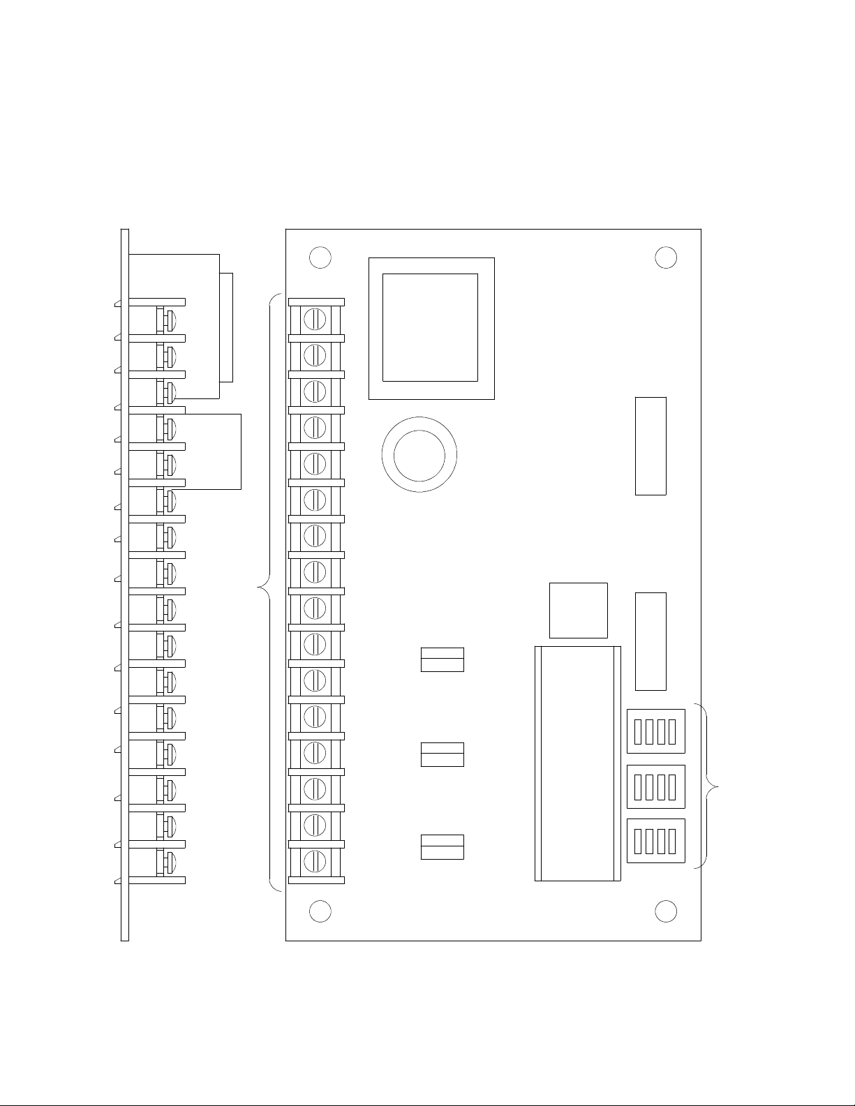
ELECTRONIC DISPENSER CONTROL
The electronic dispenser control (EDC) is a said--state circuit board, containing a microprocessor, which controls
the timing and operating functions of the dispenser. Operation of the unit is determined by connections on the
terminal strip and by the settings of DIP switches located on the circuit board. The wiring diagram supplied with
each model dispenser shows the correct wiring connections and switch settings for that model.
REMCOR
P/N 31405
1
2
3
4
5
TERMINALS
6
7
8
9
10
11
12
13
14
15
16
SW 3 CYCLE TIME
SW 2 COINCOUNT
SW 1 AGIT. TIME
(See Wiring Diagram)
1 2 3 4
OPEN
SW 3
1 2 3 4
OPEN
SW 2
1 2 3 4
OPEN
SW 1
DIP
SWITCHES
FIGURE 5. ELECTRONIC DISPENSER CONTROL
11
90678
Page 15
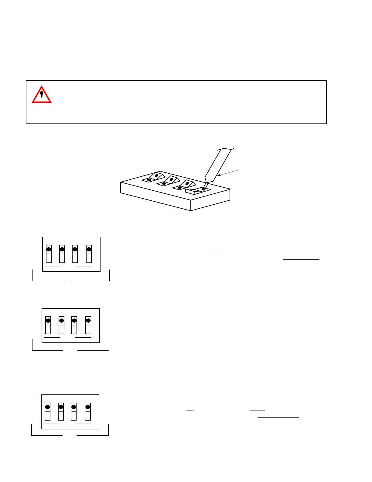
DIP SWITCH SETTINGS
Three sets of DIP switches are provided on the boardto control agitation timingand coin count options. Note
that each set of switches operates in a binary fashion, each switch has a value twice that of the preceding
switch. The switches are “off” when they are pushed up. Any combination of switches may be pushed down to
add up to the desired value, as shown below .
CAUTION: Disconnect power before setting switches
FIGURE 6. HOW TO CHANGE SWITCH SETTINGS
SHARP POINT OBJECT
5 10 20 40
1 2 3 4
OPEN
SW3
1 2 4 8
1 2 3 4
OPEN
SW2
.5 1 2 4
1 2 3 4
OPEN
SWITCH FUNCTIONS
CYCLE TIME -- MINUTES
Determines time between agitation pulses. All
switches up = no agitation, push down switches
to add up to desired time. Rangeis 5--75 minutes,
in 5 minute increments.
COIN COUNT
Determines # of coins required to vend on coin/token units. All switches up = no operation, push
down switches to add up to desired # of coins.
Range is 1 -- 15 coins, in increments of 1.
AGITATION TIME -- SECONDS
Determines length of agitation pulse. All switches
up = no agitation, push down switches to add up
to desired time. Range is .5--7.5 seconds, in .5
seconds increments.
SW1
1290678
Page 16
EDC TROUBLESHOOTING
WARNING: To prevent damage to the EDC board, never connect any load devices such as
test lamps, relays, or buzzers, or any source of external power to any terminals, except as
shown on the wiring diagram. Use only the following procedures when troubleshooting.
CAUTION: ELECTRICAL SHOCK HAZARD.
This is not an isolated low voltage system,, Although low voltages are present on the EDC
board, the circuit is tied to the hot side of the A.C. power line, and the entire board i s at 120
volts with respect to ground. Use the same cautions normal ly used when servicing 120 volt
circuits to prevent electric shock.
TESTING INPUT SWITCHES (terminal 3--13)
To conform proper operation of input switches (such as the vend switch), disconnect power from the unit, and
disconnect the device wires from the EDC terminal board. Connect an ohmmeter or continuity tester to the
switch wires, and confirm that resistance is low when the switch is closed, and high when the the switch is open.
Replace the switch if defective.
NOTE: When testing vend switch #1 on models which utilize the coin count function, the input
switch must be operated the number of times indicated by the setting of the coin count
switch (SW2) in orders to trigger vending. Also if SW2 is set to “o” (al l switches up) no vend
will occur, regardless of the number of times the vend switch is operated.
TEST OUTPUT DEVICES
If gate solenoids or agitator motor do not function check the following.
Blown fuse in solenoidcircuit (replace and check solenoid and gate mechanism.
Faulty ,motor relay (replace).
Motor protector tripped (reset red button on motor)
If all external devices appear to be ok and the EDC board is suspected, proceed as follows.
Use of A.C. voltmeter set to a range of 150 volts (or higher) to measure the voltage between the power line
neutral (terminal 1 on the EDC board) and the appropriate output terminal. B efore testing outputs, confirm
the presence of line voltage (105--132 V) at terminals 1--2 of the EDC board. Make measurements with the
dispenser both non--vending and ending, and compare results with the following chart to determine problem cause.
Non--vending vending problem
volts operation volts operation
0 no line voltage yes normal
0 no line voltage no faulty output device
Line voltage no line voltage no disconnected or faulty output device.
0 no 0 no faulty EDC
0 no less than full yes/no faulty EDC
line voltage
NOTE: Failure of the EDC board would result from a faulty output device. Therefore, if EDC board is
faulty, check the external devices for short circuits or other problems before connecting to a new
board.
13
90678
Page 17

ELECTRIC BOX COMPONENTS
31406 FUSE -- GATE SOLENOID
31375 AGITATION RELAY
31405 ELECTRONIC DISPENSER CONTROL
31001 ICE LEVEL THERMOSTAT
31507 NOISE FILTER ASSEMBLY
30385 PORTION CONTROL SWITCH
31480 SERVICE SWITCH
31441 POTIENTIOMETER -- PORTION CONTROL ADJ.
DOOR COMPONENTS
31249 LOW ICE LIGHT
31364 COIN SWITCH (--VT MODELS ONLY)
31365 COINT RETURN ELECTRO--MAGNET (VT MODELS ONLY)
30895 KEY SWITCH (--VK MODELS ONLY)
30894 DISPENSE BUTTON W/SWITCH (--MODELS ONLY)
70461 T--HANDLE
70458 CYLINDER LOCK
HOPPER ASSEMBLY COMPONENTS
31470 GATE SOLENOID ASSEMBLY
31094 SOLENOID
10077 PIVOT BUSHING
10080 GATE ROD
10081 ROD BUSHING
22890 GATE ARM
21491 GATE SLIDE
50752 ISOLATER (3 REQUIRED)
70438 REBUILDING KIT (INCLUDES: 1 SPRING, 12 COTTER PIN, 2 RETAINING CLIPS,
2 BUMPERS AND 1 GATE ROD)
22047 AGITATOR
31197 AGITATOR MOTOR
30794 MOTOR HEATER
21991 T” STAT BULB TUBING
22040 ICE LEVEL BAR
50891 TEFLON SEAL (MOTOR SHAFT)
MISCELLANEOUS COMPONENTS
50898 DOOR (ALCOVE)
70484 GRILL (ALCOVE)
50968 ICE CHUTE ASSEMBLY
22111 DOOR LATCH
30528 INTERLOCK SWITCH
90678 OWNERS INSTRUCTION MANUAL
1490678
Page 18

90803 WIRING DIAGRAM
ACCESSORIES
31351 COIN ACCEPTOR (QUARTERS)
31352 COIN ACCEPTOR (.900 TOKEN)
31250 PUSHBUTTON VEND PACKAGE
31252 KEY VEND PACKAGE
31251 COIN VEND PACKAGE
70467 CASH LOCK BOX
ICEMAKER INSTALLATION KITS
01930 SUNBEAM SERIES C--20, C--40, C--61
01931 MANITOWAC SERIES 200, 400
01932 KOLD DRAFT SERIES GT7, GT8
01935 SCOTSMAN MH--750
01936 SCOTSMAN CM--450
15
90678
Page 19

TW200--V, VT, VK S ERVICE PARTS
1690678
Page 20

IMI CORNELIUS INC.
ONE CORNELIUS PLACE
ANOKA, MN. 55303--6234
TELEPHONE (800) 238--3600
FACSI MI LE (612) 422--3232
TECH SVC 1-800-535-4240
WARRANTY
IMI Cornelius Inc. and Remcor Products Company warrants that all equipment and parts are free from defects
in material and workmanship under normal use and service. For a copy of the warranty applicable to your
Cornelius and or Remcor product, in your country, please write, fax or telephone the IMI Cornelius office nearest you. Please provide the equipment model number, serial number and the date of purchase.
IMI Cornelius Offices
AUSTRALIA D P.O. 210, D RIVERWOOD, D NSW 2210, AUSTRALIA D (61) 2 533 3122 D FAX (61) 2 534 2166
AUSTRIA D AM LANGEN FELDE 32 D A-1222 D VIENNA, AUSTRIA D (43) 1 233 520 D FAX (43) 1-2335-2930
BELGIUM D BOSKAPELLEI 122 D B-2930 BRAASCHAAT, BELGIUM D (32) 3 664 0552 D FAX (32) 3 665 2307
BRAZIL D RUA ITAOCARA 97 D TOMAS COELHO D RIO DE JANEIRO, BRAZIL D ( 55) 21 591 7150 D FAX (55) 21 593 1829
ENGLAND D TYTHING ROAD ALCESTER D WARWICKSHIRE, B 49 6 EU, ENGLAND D (44) 789 763 101 D FAX (44) 789 763 644
FRANCE D 71 ROUTE DE ST . DENIS D F-95170 DEUIL LA BARRE D PARIS, FRANCE D (33) 1 34 28 6200 D FAX (33) 1 34 28 6201
GERMANY D CARL LEVERKUS STRASSE 15 D D-4018 LANGENFELD, GERMANY D (49) 2173 7930 D FAX (49) 2173 77 438
GREECE D 488 MESSOGION AVENUE D AGIA PARASKEVI D 153 42 D ATHENS, GREECE D (30) 1 600 1073 D FAX (30) 1 601 2491
HONG KONG D 1104 TAIKOTSUI CENTRE D 11-15 KOK CHEUNG ST D TAIKOKTSUE, HONG KONG D (852) 789 9882 D FAX (852) 391 6222
ITALY D VIA PELLIZZARI 11 D 1-20059 D VIMARCATE, ITALYD (39) 39 608 0817 D FAX (39) 39 608 0814
NEW ZEALAND D 20 LANSFORD CRES. D P.O. BOX 19-044 AVONDALE D AUCKLAND 7, NEW ZEALAND D (64) 9 8200 357 D FAX (64) 9 8200 361
SINGAPORE D 16 TUAS STREET D SINGAPORE 2263 D (65) 862 5542 D FAX (65) 862 5604
SPAIN D POLIGONO INDUSTRAIL D RIERA DEL FONOLLAR D E-08830 SANT BOI DE LLOBREGAT D BARCELONA, SPAIN D (34) 3 640 2839 D FAX (34) 3 654 3379
USA D ONE CORNELIUS PLACE D ANOKA, MINNESOTA D (612) 421-6120 D FAX (612) 422-3255
Manualnumber
17
Page 21

IMI CORNELIUS INC.
Corporate Headquarters:
Anoka, Minnesota 55303-6234
One Cornelius Place
(612) 421-6120
(800) 238-3600
 Loading...