

Page 1
Installation Instructions
UNIVERSAL 750 PRE-MIX
DISPENSER
IMI CORNELIUS INC.
One Cornelius Place
Anoka, MN. 55303--6234
Telephone(800) 238--3600
Facsimile (612) 422--3232
Part No. 189159000
August 20, 1964
Revised: January 22, 1991
THIS DOCUMENT CONTAINS IMPORTANT INFORMATION
This Installation Manual must be read and understood before starting to install or operate this equipment.
IMI CORNELIUS INC; 1964-91Ó
Printed in U.S.A.
Page 2

Page 3

TABLE OF CONTENTS
GENERAL INFORMATION 1. . . . . . . . . . . . . . . . .
GENERAL DESCRIPTION 1. . . . . . . . . . . . . . .
UNIT DESCRIPTION 1. . . . . . . . . . . . . . . . . . . .
THEORY OF OPERA TION 2. . . . . . . . . . . . . .
INSTALLA TION 5. . . . . . . . . . . . . . . . . . . . . . . . . . .
UNP ACKING AND INSPECTION 5. . . . . . . . .
IDENTIFICA TION OF LOOSE--SHIPPED
P ARTS 5. . . . . . . . . . . . . . . . . . . . . . . . . . . . . . . .
SELECTING LOCATION 5. . . . . . . . . . . . . . . . .
INSTALLING UNIT 5. . . . . . . . . . . . . . . . . . . . . .
LOCA TING UNIT 5. . . . . . . . . . . . . . . . . . . . .
DRAIN CONNECTIONS 6. . . . . . . . . . . . . . .
ROUTING UNIT PRODUCT INLET LINES AND
DRIP TRAY DRAIN HOSE OUT OF UNIT CAB-
INET 6. . . . . . . . . . . . . . . . . . . . . . . . . . . . . . . .
CONNECTING UNIT PRODUCT INLET
LINES 6. . . . . . . . . . . . . . . . . . . . . . . . . . . . . . .
INSTALLING DISPENSING VALVES
KNOBS 6. . . . . . . . . . . . . . . . . . . . . . . . . . . . . .
FILL EVAPORATOR TANK AND STAR T REFRIG-
ERA TION SYSTEM 6.. . . . . . . . . . . . . . . . . . . .
PREP ARING UNIT FOR OPERATION 7. . . . .
UNIT OPERATION 7. . . . . . . . . . . . . . . . . . . . . .
OPERA TORS INSTRUCTIONS 9. . . . . . . . . . . . .
OPERA TING CONTROLS 9. . . . . . . . . . . . . . .
DISPENSING VALVE LEVER 9. . . . . . . . . . .
UNIT POWER SWITCH 9. . . . . . . . . . . . . . .
DAIL Y PRE OPERATION CHECK 9. . . . . . . . .
UNIT OPERATION 9. . . . . . . . . . . . . . . . . . . . . .
ADJUSTMENTS 9. . . . . . . . . . . . . . . . . . . . . . . .
ADJUSTING PRODUCT TANKS CO2 REG-
ULA TORS 9. . . . . . . . . . . . . . . . . . . . . . . . . . .
ADJUSTING DISPENSED PRODUCT FLOW
RA TE 9. . . . . . . . . . . . . . . . . . . . . . . . . . . . . . . .
REPLENISHING CO2 SUPPLY 9. . . . . . . . . . .
REPLENISHING PRODUCT SUPPLY 9. . . . .
CLEANING AND SANITIZING 9. . . . . . . . . . . .
DAIL Y CLEANING OF UNIT 9. . . . . . . . . . . .
WEEKL Y CLEANING OF DISPENSING
V ALVES 9. . . . . . . . . . . . . . . . . . . . . . . . . . . . .
SANITIZING UNIT 9. . . . . . . . . . . . . . . . . . . .
CHECKING CONDENSER COIL FOR RESTRIC-
TIONS 9. . . . . . . . . . . . . . . . . . . . . . . . . . . . . . . . .
CHECKING ICE WATER BATH 9. . . . . . . . . . .
SERVICE AND MAINTENANCE 11.. . . . . . . . . . .
PREP ARING UNIT FOR SHIPPING, RELOCAT-
ING, OR STORING 1 1.. . . . . . . . . . . . . . . . . . . .
PAGE
TOP COVER, ACCESS GRILLES, AND DRIP
TRA Y REMOVAL ) 1 1.. . . . . . . . . . . . . . . . . . . . .
TOP COVER REMOV AL 1 1.. . . . . . . . . . . . . .
ACCESS GRILLES REMOVAL 1 1.. . . . . . . .
DRIP TRAY REMOVAL 11. . . . . . . . . . . . . . . .
PERIODIC INSPECTION 11.. . . . . . . . . . . . . . .
ADJUSTMENTS 1 1.. . . . . . . . . . . . . . . . . . . . . . .
ADJUSTING PRODUCT TANKS CO2 REG-
ULA TORS 11.. . . . . . . . . . . . . . . . . . . . . . . . . .
ADJUSTING DISPENSED PRODUCT FLOW
RA TE 1 1.. . . . . . . . . . . . . . . . . . . . . . . . . . . . . . .
REPLENISHING CO2 SUPPLY 1 1.. . . . . . . . . .
REPLENISHING PRODUCT SUPPLY 12. . . . .
PRODUCT FLAVOR CHANGE 12. . . . . . . . . . .
CLEANING CONDENSER COIL 12. . . . . . . . . .
CHECKING ICE WATER BATH ) 12.. . . . . . . . .
CLEANING EVAPORATOR TANK ) 14. . . . .
CLEANING AND SANITIZING 15. . . . . . . . . . . .
DAIL Y CLEANING OF UNIT 15. . . . . . . . . . . .
WEEKL Y CLEANING OF DISPENSING
V ALVES ) 16. . . . . . . . . . . . . . . . . . . . . . . . . . . .
SANITIZING UNIT 16. . . . . . . . . . . . . . . . . . . .
TROUBLESHOOTING 21. . . . . . . . . . . . . . . . . . . . .
NO PRODUCT DISPENSED. 21.. . . . . . . . . . . .
DISPENSED PRODUCT COMES OUT OF DISPENSING VALVE CLEAR BUT FOAMS IN CUP
OR GLASS 21. . . . . . . . . . . . . . . . . . . . . . . . . . . . .
DISPENSED PRODUCT FOAMS AS IT LEAVES
DISPENSING VALVE. 21. . . . . . . . . . . . . . . . . . .
REFRIGERA TION SYSTEM 22. . . . . . . . . . . . . .
COMPRESSOR DOES NOT OPERA TE. 22.
COMPRESSOR WILL NOT STOP AFTER
SUFFICIENT ICE BANK IS FORMED. 22. .
COMPRESSOR OPERATES CONTINUOUSLY
BUT DOES NOT FORM SUFFICIENT ICE
BANK. 22.. . . . . . . . . . . . . . . . . . . . . . . . . . . . . .
CONDENSER FAN MOTOR NOT
OPERA TING. 23. . . . . . . . . . . . . . . . . . . . . . . .
AGITA TOR MOTOR NOT OPERATING. 23.
COMMERCIAL WARRANTY 25. . . . . . . . . . . . . . .
LIST OF FIGURES
FIGURE 1. UNIVERSAL 750 PRE-MIX DISPENS-
ER 1. . . . . . . . . . . . . . . . . . . . . . . . . . . . . . . . . . . .
FIGURE 2. FLOW DIAGRAM 3. . . . . . . . . . . . .
FIGURE 3. PAR TS IDENTIFICATION 13. . . . . .
FIGURE 4. EVAPORATOR TANK (STANDARD
UNIT SHOWN) 14. . . . . . . . . . . . . . . . . . . . . . . . .
FIGURE 5. CLEANING DISPENSING VALVE 15
FIGURE 6. WIRING DIAGRAM 18. . . . . . . . . . .
i
PAGE
189159000
Page 4

TABLE OF CONTENTS CONT’D
FIGURE 7. INSTRUCTIONS FOR CRIMPING
TUBE CLAMPS 19. . . . . . . . . . . . . . . . . . . . . . . . .
PAGE
PAGE
LIST OF TABLES
TABLE 1. DESIGN DA TA 1. . . . . . . . . . . . . . . . .
TABLE 2. LOOSE-SHIPPED P ARTS 5.. . . . .
189159000
ii
Page 5
GENERAL INFORMATION
IMPORTANT: To the user of this manual -- This
manual is a guide for installing, operating, and
maintaining this equipment. Refer to Table of
Contents for page location of detailed
information pertaining to questions that arise
during installation, operation, service and
maintenance, or troubleshooting this equipment.
GENERAL DESCRIPTION
This section gives the unit description, installation
requirements, theory of operation, design data, and
flow diagram for the Universal 750 Four-- Flavor Pre-Mix Dispenser (hereafter referred to as a unit).
UNIT DESCRIPTION
The dispenser (see Figure 1) is a compact unit that
may be installed free standing or under a
counter or bar.
Installation of the LOOSE-- SHIPPED PARTS, (see
Table 2-- 1), connection to a grounded electrical outlet
with proper electrical requirements, filling evaporator
tank with water, and connection to product tanks with
regulated CO2pressure are all that is required to set
unit up for operation. A 6--inch leg kit (P/N
187416-- 000) is available. Also available is a four
caster kit (P/N 316290-- 000) to make unit mobile.
CAUTION: Before shipping, storing,
or relocating this Unit, the syrup
systems must be sanitized and all
sanitizing solution must be purged from the
syrup systems. All water must also be
purged from the plain and carbonated water
systems. A freezing ambient environment
will cause residual water in the Unit to freeze
resulting in damage to internal components.
Table 1. Design Data
Model Numbers:
Universal 750 (domestic) 284729-- 000
Standard Unit
Universal 750 (domestic) with 284780-- 000
Sealed Evaporator Tank
Universal 750 (export) 494729-- 000
Overall Dimensions:
Height 37--1/4 inches
Width 16 inches
Depth (with drip tray) 22 inches
FIGURE 1. UNIVERSAL 750 PRE-MIX DISPENSER
Table 1. Design Data (cont’d)
Weights:
Shipping (1Carton) 159 pounds
Dry Weight 140 pounds
With Evaporator Tank full 225 pounds
of Water
Ice Bank Weight 46 pounds
Capacities:
Unit Water Bath (no ice bank)
approx.
Dispensing Rate:
6-- oz. drinks @ 4/minute *763
6-- oz. drinks @ 6/minute *507
Recovery Rate 3 drinks/minute
NOTE: *Number of 6-- oz. drinks that can be dispensed at 40° F or below with 75° F product inlet
temperature and 75° F ambient.
Ambient Operating Temperature 40°F to 100°F
Electrical Requirements:
Operating Voltage (domestic) 1 15 VAC, 60
Current Draw (domestic) 8.1 amps
Operating Voltage (export) 230 VAC, 50
Current Draw (export) 3 amps
1 189159000
10 gallons
Hz
Hz
Page 6

THEORY OF OPERATION (see Figure 2)
A CO2cylinder delivers carbon dioxide gas (CO2)
through regulated CO2regulators to product tanks.
When dispensing lever is opened, CO2pressure exerted upon product tanks pushes product from tanks,
through unit cooling coils, to dispensing valves resulting in cold dispensed drinks.
When unit power cord has been plugged into electrical outlet and power switch on back of unit has been
flipped to ‘‘ON’’ (up) position, compressor, condenser
fan motor, and agitator motor will start and begin
forming an ice bank. When full ice bank has been
formed, compressor and condenser fan motor will
stop but agitator motor will continue to operate circulating ice water bath in evaporator tank. Evaporator
tank ice bank sensing bulb will cycle compressor and
condenser fan motor on and off as required to maintain full ice bank.
2189159000
Page 7

FIGURE 2. FLOW DIAGRAM
CYLINDER
REGULATOR (2)
2
2
CO
CHECK VALVE (4)
CO
PRODUCT TANK (4)
DISPENSING
PRODUCT COIL (4)
ICE WATER
VALVE (4)
BATH DISPENSER
2
LINE LEGEND
PRODUCT
CO
3
189159000
Page 8

THIS PAGE LEFT BLANK INTENTIONALLY
4189159000
Page 9
INSTALLATION
This section covers unpacking and inspection, identification of LOOSE--SHIPPED PARTS, selecting location, installing unit, preparing unit for operation, and
unit operation.
UNPACKING AND INSPECTION (see Figure
3)
NOTE: The unit was thoroughly inspected before
leaving factory and carrier has accepted and
signed for it. Any damage or irregularities
should be noted at time of delivery and immediately reported to delivering carrier. Request a
written inspection report from Claims Inspector
to substantiate any necessary claim. File claim
with delivering carrier, not with IMI Cornelius Inc.
1. After unit has been removed from shipping carton, remove shipping tape and other packing
material. Inspect for shipping damage and follow
procedure in preceding NOTE if damage is evident.
2. Unpack item listed in LOOSE--SHIPPED
P ARTS. Make sure all items are present and in
good condition.
2. CUP REST (item 2) to be installed in DRIP
TRA Y
(item 3).
3. DRIP TRAY (item 3) to be installed on unit by
inserting rear edge of tray under lip of valve trim
panel and lifting up until bottom tray supports
are inserted in square holes provided in front
panel. Lock drip tray in place by slight downward pressure.
4. DECALS, DISPENSING VALVES KNOBS (item
7) to be installed on DISPENSING V ALVES
KNOBS (item 4)
5. DISPENSING VALVES KNOBS (item 4) to be
installed on dispensing valves by pushing knobs
down into place on valves levers.
6. Applicable ADAPTERS (item 5) to be used to
connect product inlet lines from product tanks to
unit product inlet lines. REDUCERS (item 6)
may be used to connect unit product inlet lines
directly to product tanks quick disconnects provided disconnects have 1/4-- inch flare (7/16--20)
male fittings.
SELECTING LOCATION
Table 2. Loose-Shipped Parts
Item
No. Part No. Name Qty.
1 188090 Leveling Legs 4
2 186642 Cup Rest 1
3 186573-- 039 Drip Tray 1
4 151741-- 039 Dispensing Valve
Knob
5 150807-- 100 Adapter, 7/16-- 20
Male by 1/2--16 Male
150807-- 200 Adapter, 1/2-- 16
Male by 1/2--16 Male
(domestic unit only)
6 31 1245 Reducer, 7/16--20
Female by 1/2--16
Male
7 317904-- 999 Decal, Dispensing
V alve Knob (as
ordered)
IDENTIFICATION OF LOOSE--SHIPPED
PARTS (see Figure 3)
1. LEVELING LEGS (item 1) to be installed in
threaded holes provided on unit base (only units
installed outside the United States).
NOTE: For identification purposes, side of unit
dispensing valves are on is designated ‘‘front’’ of
unit. This unit may be installed free standing or
under counter or bar. Locate unit so following
requirements are satisfied.
1. Near a properly grounded electrical outlet with
proper electrical requirements. No other electrical appliance should be connected to this circuit.
ALL ELECTRICAL WIRING MUST CONFORM
4
4
4
4
TO NATIONAL AND LOCAL ELECTRICAL
CODES.
2. Air circulation through condenser coil, required
for cooling coil, is drawn in through air intake
grille on front of unit and is exhausted out
through grilles on sides and back of unit. When
locating unit, make sure grilles are not restricted
to insure proper air circulation through unit.
INSTALLING UNIT
LOCATING UNIT
4
Areas Outside United States (Canada, Europe, etc.)
Install LEVELING LEGS (item 1) in threaded holes
on each corner of unit base. Adjust each leveling leg
until unit sits level and stands solid. Make sure all
leveling legs are in contact with floor.
Areas Within United States -- To comply with National
Sanitation Foundation (NSF) requirements, unit must
be sealed to floor and LEVELING LEGS (item 1)
may not be used. Perform following procedure to
install unit.
5 189159000
Page 10

NOTE: An alternate arrangement for following
installation method described would be to install
available 6--inch leg kit (P/N 187416--000) or four
caster kit (P/N 316290--000).
1. Slide unit into operating position.
2. Tilt unit up to expose bottom of base.
3. Liberally apply silastic sealant such as Dow
Corning RTV 731 or equivalent around edges on
bottom of base.
NOTE: Do not move unit after positioning or seal
from unit base to floor will be broken.
4. Lower unit into operating position to complete
seal from unit base to floor. Apply additional
sealant around bottom of unit base. Seal must
have a minimum radius of 1/2--inch to prevent
crevices and to insure a complete seal.
DRAIN CONNECTIONS
ROUTING UNIT PRODUCT INLET LINES AND
DRIP TRAY DRAIN HOSE OUT OF UNIT
CABINET
IMPORTANT: When routing product inlet lines
out through side of unit, use care to see that
lines do not come in contact with compressor or
hot discharge line. Accidental contact may result
in foaming of dispensed product.
All internal connections have been made at factory.
Unit product inlet lines and drip tray drain hose may
be brought out through either side or back product
line access holes on unit cabinet. If either leg kit (P/N
187416-- 000) or four caster kit (P/N 316290--000) are
used, product lines and drip tray drain hose may be
routed out through hole in unit base.
CONNECTING UNIT PRODUCT INLET LINES
NOTE: REDUCERS (item 6) may be used to connect unit inlet supply lines directly to product
tanks quick disconnects provided disconnects
have 1/4--inch flare (7/16--20) male fittings.
NOTE: Drip tray drain hose routed to waste container is not recommended due to sanitation and
cleaning problems. Connection of drain hose to
permanent drain is recommended.
Drip Tray Drain Hose -- The drip tray, as provided, is
self-- contained and must be emptied periodically. If
permanent drain is desired, cut out center of drain
connection on drip tray . Be sure to remove all plastic
to open drain to its maximum inside diameter preventing any rough edges which will trap dirt. Install
DRIP TRAY (item 3) by inserting rear edge of tray
under lip of valve trim panel and lifting up until bottom tray supports are inserted in square holes provided in front panel. Lock drip tray in place by a slight
downward pressure. Connect drain hose below drip
tray to drain connection on drip tray . This drain hose
runs to the inside of the unit and must be brought out
with unit product inlet lines and routed to permanent
drain or waste receptacle.
Evaporator Tank Drain Hose -- A drain hose, connected to bottom of evaporator tank, is provided to
drain water from tank. Plug in end of drain hose
should be removed only when desired to drain tank.
Standard Unit Evaporator Tank Overflow Tube -Overflow tube from evaporator tank is routed to water tight pan in base of unit. During initial forming of
ice bank and during periods of high humidity, excess
water will overflow from evaporator tank to pan and
be evaporated.
Unit With Sealed Evaporator Tank Overflow Tube
--Overflow tube from evaporator tank is routed out
through rear panel of unit (see Figure 3). Plug in end
of overflow tube should be removed only when ice
water bath is being replenished, and during initial
forming of ice bank.
1. Install applicable ADAPTERS (item 5) on ends
of unit product inlet lines.
NOTE: The numbered unit product inlet lines to
dispensing valves are labeled to identify dispensing valve they serve. For example: The line
labeled ‘‘1’’ must be connected to system that
provides product to be dispensed from NO. 1
dispensing valve. (NO. 1 dispensing valve is
valve on right side when facing front of unit.)
2. Connect .265 I.D. or larger braided tubing from
product tanks to unit product inlet lines.
INST ALLING DISPENSING VALVES KNOBS
1. Install DECALS (item 7) on DISPENSING
V ALVES KNOBS (item 4)
2. Install knobs on dispensing valves by pushing
knobs down into place on valves levers.
FILL EVAPORATOR TANK AND START
REFRIGERATION SYSTEM
1. Make sure plug is secure in end of evaporator
tank drain hose inside cabinet.
2. Remove four screws securing top cover on unit,
then lift cover straight up and off.
3. Standard Unit. Fill evaporator tank up to top of
stainless steel product coils with approximately
10 gallons of water. USE LOW--MINERAL-CONTENT WA TER WHERE A LOCAL WATER
PROBLEMS EXISTS.
Unit with sealed evaporator tank.
A. Remove plug from end of evaporator tank
overflow tube (see Figure 3).
6189159000
Page 11
B. Remove water fill hole plug from evapora-
tor tank cover.
6. Plug unit power cord into a properly grounded
electrical outlet.
C. Fill evaporator tank until water starts flow-
ing from overflow tube. USE LOW--MINERAL-- CONTENT WATER WHERE A LOCAL
WATER PROBLEM EXISTS.
D. Install plug in water fill hole in evaporator
tank cover.
E. Install plug in end of evaporator tank over-
flow tube after full ice bank has been
formed.
4. Install cover on unit and secure with four
screws.
5. Flip unit power switch (see Figure 3) to ‘‘OFF’’
(down) position.
WARNING: Unit must be electrically
grounded to prevent possible fatal
electrical shock or serious injury to
operator. Unit power cord is equipped with a
three--prong plug. If a three--hole (grounded)
electrical outlet is not available, use an
approved method to ground unit.
7. Flip unit power switch to ‘‘ON’’ (up) position.
8. With unit power switch in ‘‘ON’’ position, make
sure compressor, condenser fan motor, and agitator motor start to begin forming an ice bank.
When full ice bank is formed, compressor and
condenser fan motor will stop but agitator motor
will continue to operate circulating ice water
bath in evaporator tank.
PREPARING UNIT FOR OPERATION
1. Adjust product tanks CO2regulators as
instructed.
2. Connect product tanks into systems. Check for
leaks and tighten loose connections.
UNIT OPERATION
1. Dispense from dispensing valve until air is bled
from system and product is dispensed.
2. Repeat step 1 preceding to purge air from remaining systems.
3. Adjust dispensed product flow rate as
instructed.
7 189159000
Page 12

THIS PAGE LEFT BLANK INTENTIONALLY
8189159000
Page 13

OPERATORS INSTRUCTIONS
This section covers operating controls, daily pre-operation check, unit operation, adjustments, replenishing CO2and product supplies, cleaning and sanitizing unit, checking condenser coil for restrictions, and
checking ice water bath.
OPERATING CONTROLS (see Figure 3)
DISPENSING VAL VE LEVER
Dispensing valve lever need only to be pulled forward to dispense product and released when cup or
glass is full.
UNIT POWER SWITCH
Unit power switch, located on back of unit, must be
in ‘‘ON’’ (up) position before unit will operate. PLACE
UNIT POWER SWITCH IN ‘‘OFF’’ (DOWN) POSITION BEFORE PERFORMING INTERNAL SERVICE AND MAINTENANCE.
DAILY PRE OPERATION CHECK
1. Make sure CO2cylinder regulator assembly
2000-- psi gage indicator is not in shaded
(‘‘change CO2cylinder’’) portion of dial. If so,
CO2cylinder is almost empty and must be replaced.
REPLENISHING CO2SUPPLY
NOTE: When indicator on CO2cylinder regulator assembly 2000--psi is in shaded (‘‘change CO2cylinder’’) portion of the dial, CO2cylinder is almost
empty and should be changed. CO2supply should
be checked daily and if necessary, replenished as
instructed.
REPLENISHING PRODUCT SUPPLY
Product supply should be checked daily and if necessary , replenished as instructed.
CLEANING AND SANITIZING
DAILY CLEANING OF UNIT
Daily cleaning of unit should be performed at end of
daily operation as instructed.
WEEKLY CLEANING OF DISPENSING
VAL VES
Dispensing valves should be cleaned at least once a
week as instructed.
2. Sufficient product supply in all product tanks. If
not, replenish product supply as instructed.
3. Make sure drip tray is clean and clean cup rest
is in place in drip tray.
UNIT OPERATION
1. Make sure unit power switch, located on back of
unit, is in ‘‘ON’’ (up) position.
2. Hold cup or glass under dispensing valve. Pull
dispensing valve lever forward and dispense
until cup or glass is full, then release lever.
ADJUSTMENTS
ADJUSTING PRODUCT T ANKS CO
REGULATORS
Product tanks CO2regulators should be periodically
checked for proper pressure settings and if necessary , adjusted as instructed.
ADJUSTING DISPENSED PRODUCT FLOW
RATE
2
SANITIZING UNIT
Product systems should be sanitized as instructed
every 90 days following Sanitizer Manufacturer ’s recommendations.
CHECKING CONDENSER COIL FOR
RESTRICTIONS
NOTE: Air circulation through condenser coil,
required to cool coil, is drawn in through air intake grille on unit front panel and is exhausted
out through grilles on sides and back of unit.
Restricting air circulation through unit will decrease its cooling efficiency .
Area in front, sides, and back of unit must be kept
free of obstructions at all times which would prevent
air flow in and out of unit. Cooling unit condenser coil
should be periodically cleaned to maintain cooling
efficiency as instructed.
CHECKING ICE WATER BATH
Product flow rate of dispensed product should be
periodically checked and if necessary, adjusted as
instructed.
A ‘‘gurgle’’ heard from unit indicates water level in
evaporator tank is low and more water should be
added for maximum product cooling as instructed.
1891590009
Page 14

THIS PAGE LEFT BLANK INTENTIONALLY
10189159000
Page 15
SERVICE AND MAINTENANCE
This section describes service and maintenance procedures to be performed on the unit.
IMPORTANT: Only qualified personnel should
service internal components or electrical wiring.
PREPARING UNIT FOR SHIPPING,
RELOCATING, OR STORING
CAUTION: Before shipping, storing,
or relocating this Unit, the syrup
systems must be sanitized and all
sanitizing solution must be purged from the
syrup systems. All water must also be
purged from the plain and carbonated water
systems. A freezing ambient environment
will cause residual water in the Unit to freeze
resulting in damage to internal components.
TOP COVER, ACCESS GRILLES, AND
DRIP TRAY REMOVAL (see Figure 3)
TOP COVER REMOVAL
Remove four screws securing unit top cover, then lift
cover straight up and off.
ACCESS GRILLES REMOVAL
Remove four screws securing access grille on unit,
then remove grille.
DRIP TRAY REMOVAL
1. If drip tray drain hose is used, disconnect drain
hose from bottom of drip tray.
2. Lift drip tray up slightly, and at same time, tip
front of drip tray up to disengage its bottom supports from square holes in unit front panel. Slide
drip tray down to disengage its upper rear edge
from under valve trim panel lip.
3. Install drip tray on unit by reversing removal procedure.
PERIODIC INSPECTION
6. Check dispensing valves for dripping that indicates leaking and repair as necessary.
ADJUSTMENTS
ADJUSTING PRODUCT T ANKS CO
REGULATORS
NOTE: To readjust CO2regulator to a lower setting, loosen adjusting screw lock nut, then turn
screw to the left (counterclockwise) until pressure gage reads 5--psi lower than new setting
will be. Turn adjusting screw to the right (clockwise) until gage registers new setting, then tighten lock nut.
Set product tanks CO2regulators, using Cornelius
PRE-- MIX COMPUTER slide rule or bottling room
chart, at equilibrium pressure for highest temperature
encountered between product tank storage area and
cooling unit plus 5-- psig operating pressure for lines
10-- feet in length or less and no vertical lift. Add one
pound for every 10-- feet over initial 10--feet of product tank--to--cooling unit line length and one pound
for every 2--feet of vertical lift. Add one pound for
every product tank on line over three tanks. MAXIMUM UNIT INLET PRESSURE MUST NOT EXCEED 100--PSIG. Loosen lock nut on CO2cylinder
adjusting screw, then turn adjusting screw to the right
(clockwise) until gage registers desired pressure.
Tighten adjusting screw lock nut.
ADJUSTING DISPENSED PRODUCT FLOW
RATE
Rotate dispensing valve Compensator Adjusting
Screw (Figure 3) to the left (counterclockwise) for
higher product flow rate or to the right (clockwise) for
lower product flow rate.
2
REPLENISHING CO2SUPPLY
NOTE: When indicator on CO2cylinder regulator
assembly 2000--psi gage is in shaded (‘‘change
CO2cylinder’’) portion of dial, CO2cylinder is
almost empty and should be changed.
4. Check unit condenser coil for accumulation of
dust, lint, and grease which will restrict air flow
through condenser coil which will decrease unit
cooling efficiency.
5. Check area in front, sides, and back of unit for
obstructions. These areas must be kept clear at
all times which would prevent air flow in and out
of unit.
1. Fully close (clockwise) CO2cylinder valve.
2. Slowly loosen CO2regulator assembly coupling
nut allowing CO2pressure to escape, then remove regulator assembly from empty CO2cylinder.
3. Unfasten safety chain and remove empty CO
cylinder.
1 1 189159000
2
Page 16
WARNING: To avoid personal injury
and/or property damage, always
secure CO2cylinder with safety chain
to prevent it from falling. Should valve
become accidentally damaged or broken off,
CO2cylinder can become an unguided
missile.
4. Position CO2cylinder and secure with safety
chain.
5. Make sure gasket is in place inside CO2regulator coupling nut, then install regulator on CO
cylinder.
6. Open (counterclockwise) CO2cylinder valve
slightly to allow lines to slowly fill with gas, then
open valve fully to back--seat valve. (Back--seating valve prevents leakage around valve shaft).
7. Check CO2connections for leaks. Tighten loose
connections.
REPLENISHING PRODUCT SUPPLY
3. V acuum or use a soft brush to clean condenser
coil. If available, use low--pressure compressed
air.
4. Install grille on front panel and secure with four
screws.
5. Flip unit power switch to ‘‘ON’’ (up) position.
CHECKING ICE WATER BATH (see Figures 3
and 4)
A ‘‘gurgle’’ heard from unit indicates water level in
evaporator tank is low and more water should be
2
added for maximum product cooling. Before adding
more water, ice water bath and ice bank should be
checked for cleanliness and agitator motor shaft, ice
bank sensing bulb, and anode checked for excessive
mineral deposit build--up.
1. Flip unit power switch, located on back of unit,
to ‘‘OFF’’ (down) position.
2. Remove four screws securing unit top cover,
then lift cover straight up and off.
3. Unit with sealed evaporator tank only.
1. Remove inlet (CO2) disconnect (grey) and outlet
disconnect (black) from empty product tank,
then remove tank.
2. Place full product tank in position, then connect
inlet (CO2) disconnect (grey) and outlet disconnect (black) to tank.
PRODUCT FLAVOR CHANGE
Sanitize applicable system as instructed, then install
full tank of new flavor product.
CLEANING CONDENSER COIL
NOTE: Air circulation through condenser coil,
required to cool coil, is drawn in through grille
on front panel and is exhausted out through
grilles on sides and back of unit. Restricting air
circulation through unit will decrease its cooling
efficiency .
Excessive accumulation of dust, lint, and grease on
condenser coil will restrict air flow through coil and
cause a loss of cooling efficiency . Perform following
procedure to clean condenser coil.
1. Flip unit power switch, located on back of unit,
to ‘‘OFF’’ (down) position.
2. Remove four screws securing grille on front
panel, then remove grille.
A. Remove quick disconnects (black) from
product tanks outlets.
B. Relieve pressure from systems by opening
each dispensing valve.
C. Disconnect agitator motor ground wire and
power cord.
D. Disconnect product inlet lines swivel nut
connections from fittings on evaporator
tank cover. Be careful not to lose tapered
gaskets.
E. Remove hex nuts securing evaporator tank
coils line fittings to evaporator tank cover.
F. Remove screws securing evaporator tank
cover to unit, then lift cover straight up to
remove. Be careful not to lose rubber
washers on tank coils line fittings.
4. Check condition of ice water bath and ice bank.
Ice water bath should be clear and ice bank free
of foreign particles.
5. Check agitator motor shaft, ice bank sensing
bulb, and anode for excessive mineral deposit
build-- up.
6. If cleaning of evaporator tank is necessary , refer
to CLEANING EVAPORATOR TANK in this section.
12189159000
Page 17

*WATER FILL PLUG
VALUE TRIM
PANEL
DISPENSING VALVE (4)
2
DRIP TRAY
DRAIN HOSE
ACCESS
GRILLE (4)
ACCESS GRILLE
RETAINING SCREW (4)
COMPENSAT OR
ADJUSTING
SCREW
COVER
RETAINING SCREW (2)
*EVAPORATOR TANK
OVERFLOW TUBE
3
PLUG
EVAPORATOR TANK
DRAIN HOSE
UNIT POWER
SWITCH
*UNIT WITH SEALED EVAPORATOR TANK.
FIGURE 3. PARTS IDENTIFICA TION
13 189159000
Page 18

ALUMINUM
SCREW
EVAPORATOR
TANK
ANODE
FIGURE 4. EVAPORATOR TANK (STANDARD UNIT SHOWN)
7. Fill evaporator tank with water up to top of stainless steel product coils. USE LOW--MINERAL-CONTENT WA TER WHERE A LOCAL WATER
PROBLEM EXISTS.
8. Unit with sealed evaporator tank only.
AGITATOR
MOTOR
CLEANING EVAPORATOR TANK (see Figure 4)
NOTE: Ice water bath should be changed as
often as necessary to keep evaporator tank
clean. A convenient time to perform this operation is at time unit is being sanitized. To save
time, water can be drained from the evaporator
tank while unit is being sanitized.
A. Install evaporator tank cover and coils line
fittings, connect agitator motor ground wire
and power cord, and connect product inlet
lines swivel nut connections to fittings on
evaporator tank cover.
B. Install quick disconnects (black) on product
tanks outlets.
C. Dispense from dispensing valves to bleed
air from systems.
D. Check for leaks and repair if evident.
9. Install unit top cover and secure with four
screws.
10. Flip unit power switch to ‘‘ON’’ (up) position.
1. Flip power switch, on back of unit, to ‘‘OFF’’
(down) position.
2. Remove four screws securing unit top cover,
then remove cover.
3. Remove four screws securing either side or
back access grille, then remove grille.
4. Extend drain hose from bottom of evaporator
tank inside unit out through removed access
grille to waste receptacle or drain. Remove plug
and allow water to drain from evaporator tank.
5. Unit with sealed evaporator tank only.
Refer to step 3 CHECKING ICE WATER BA TH
and perform procedures to disconnect product
tanks from systems, relieve systems pressures,
and remove evaporator tank cover.
NOTE: If ice bank is clear and contains no foreign particles, it does not have to be melted
down. Skip steps 6 and 7 and proceed with step
8).
14189159000
Page 19
6. If ice bank is dirty, allow it to melt. Hot water
may be used to speed melting.
CAUTION: Never use an ice pick or
other instrument to remove ice from
evaporator. Such practice can result
in punctured refrigerant circuit or damage to
corrosion protective coating on evaporator
tank.
7. Wash inside of evaporator tank with a mild soap
solution.
CAUTION: Function of the anode in
the ice water bath is to draw
corrosive agents to itself and away
from evaporator tank. Make sure ice bank
sensing bulb and anode, with its rubber
insulator in place on top end, are properly
placed in their respective position. Anode
must be completely insulated from other
metal components and only an aluminum
screw must be used to secure its connecting
wire to evaporator tank. If anode is allowed
to contact other metal parts, its effectivity
will be destroyed, allowing corrosive action
to take place on evaporator tank.
8. Use fiber brush and carefully clean mineral deposit build--up from agitator motor shaft, ice
bank sensing bulb, and anode. If after cleaning
anode, and it is found to be badly corroded, replace with a new one. Make sure only an aluminum screw is used to secure anode connecting
wire to evaporator tank.
9. Rinse all parts and flush evaporator tank with
clean water.
10. Install plug in drain hose, then place hose back
inside unit.
1 1. Install grille and secure with four screws.
12. Fill evaporator tank (if no ice bank is present)
with approximately 10 gallons of water up to top
of stainless steel product coils. USE LOW-- MINERAL-- CONTENT WATER WHERE A LOCAL
WATER PROBLEM EXISTS.
13. Unit with sealed evaporator tank only.
CLEANING AND SANITIZING
DAILY CLEANING OF UNIT
NOTE: Drip tray that is connected to drain hose
routed to waste container or permanent drain
need not be removed from unit to be cleaned.
Remove cup rest, then wash out and rinse drip
tray in place on unit allowing water to escape
through drain hose to waste container or drain.
Wash and rinse cup rest, then install cup rest in
drip tray. If drip tray is not connected to drain,
proceed as follows:
1. Lift drip tray up slightly and at the same time, tip
front of drip tray up to disengage its bottom supports from square holes in unit front panel. Slide
drip tray down to disengage its upper rear edge
from under valve trim panel lip.
2. Remove cup rest from drip tray. Wash cup rest
and drip tray, then rinse them with potable water.
3. Install cup rest in drip tray, then install drip tray
on unit by reversing removal procedure.
4. Rinse out sponge with clean water, then wring
excess water out of sponge. Wipe off external
surfaces of unit, then wipe unit dry with a clean
soft cloth. DO NOT USE ABRASIVE TYPE
CLEANERS.
KNOB LEVER BONNET
FRICTION WASHER
COMPENSAT OR
O-RING
SHAFT AND
SEAT ASS’Y
BODY
INNER SLEEVE
OUTER SLEEVE
PHILLIPS-HEAD SCREW
SPRING
COMPENSAT OR
ADJUSTING
SCREW
O-RING
LEVER
BALL WASHER
KNOB
Refer to step 8 CHECKING ICE WATER BA TH
and perform procedures to install evaporator
tank cover, connect product tanks into systems,
bleed air from systems, and check for leaks.
14. Flip unit power switch on back of unit to ‘‘ON’’
(up) position. Make sure compressor condenser
fan motor, and agitator motor are operating.
FIGURE 5. CLEANING DISPENSING VALVE
15 189159000
Page 20
WEEKLY CLEANING OF DISPENSING
VAL VES (see Figure 5)
Dispensing valves should be cleaned at least weekly
for proper operation. A convenient time to clean dispensing valves is at time unit is being sanitized. Perform following procedure to clean dispensing valves.
1. Remove quick disconnects (black) from product
tanks outlets.
2. Open dispensing valves to relieve pressure on
systems.
3. Remove dispensing valve knobs by pulling
knobs up and off valves.
4. Using a spanner wrench, loosen and remove
coupling nuts from dispensing valves, then remove valves from unit.
5. Remove phillips--head screw on end of dispensing valve, then remove outer sleeve, spring, and
inner sleeve.
6. Loosen and remove knob lever bonnet securing
lever in dispensing valve body, then remove lever.
7. Slide shaft and seat assembly out through rear
of dispensing valve body .
SANITIZING UNIT
NOTE: This unit should be sanitized every 90
days following Sanitizer Manufacturer’s recommendations. Use Chlor--Tergent (Oakite Products, Inc.) or equivalent sanitizer. An economic
practice would be to arrange any product flavor
changeover to coincide with sanitizing operation.
1. Remove quick disconnects from product tanks.
Rinse quick disconnects in potable water.
2. Following Sanitizer Manufacturer ’s instructions,
fill clean empty product tank with sanitizing solution.
3. Connect tank containing sanitizing solution into
system to be sanitized.
4. Place waste container under applicable dispensing valve. Open dispensing valve to permit sanitizing solution to push product out of line, coil,
and dispensing valve. Continue to draw from
valve until only sanitizing solution is dispensed.
5. Repeat steps 3 and 4 preceding to purge product from, and install sanitizing solution in, remaining systems.
6. Follow Sanitizer Manufacturer ’s application
instructions.
8. Wash disassembled dispensing valve parts in
warm potable water.
9. Assemble dispensing valve by reversing disassembly procedure steps 5 through 7 preceding.
10. Disassemble and clean remaining dispensing
valve by performing steps 5 through 9 preceding.
1 1. Remove compensators from inside sleeve and
coupling nut assemblies.
12. Wash compensators in warm potable water,
then install compensators in sleeve and coupling nut assemblies.
13. Install dispensing valves on unit. Make sure
coupling nuts are tight.
14. Install quick disconnects on product tanks outlets.
15. Open dispensing valves to bleed air from systems and until product flows from valves.
WARNING: To avoid possible
personal injury or property damage,
do not attempt to remove product
tank cover until CO2pressure has been
released from tank.
7. Remove tank containing sanitizing solution from
system and install tank containing potable water.
WARNING: Flush sanitizing solution
from system as instructed. Residual
solution left in system could create a
health hazard.
8. Place waste container under dispensing valve.
Open dispensing valve to permit flush water to
purge sanitizing solution out of line, coil, and
dispensing valve. Continue to draw from valve
until only flush water is dispensed.
9. Install tank containing flush water on remaining
systems, then repeat step 8 preceding to flush
sanitizing solution from systems until only flush
water is dispensed.
16189159000
Page 21
WARNING: To avoid possible
personal injury or property damage,
do not attempt to remove product
tank cover until CO2pressure has been
released from tank.
1 1. Place waste container under applicable dispens-
ing valve and blow residual water from system.
12. Repeat step 11 preceding to blow residual water
from remaining systems.
Install product tanks in systems.
10. Remove tank containing flush water from system and install clean empty product tank.
Open each dispensing valve until all gas is purged
from systems and product is dispensed.
17 189159000
Page 22

AGITATION MOTOR
RECEPTACLE
POWER SWITCH
WIRE SPLICE
CAP
WHITE
POWER
CORD
GREEN
ICE BANK
CONTROL
COMPRESSOR
CONDENSER
FAN MOTOR
CONTROL BOX
FIGURE 6. WIRING DIAGRAM
18189159000
Page 23
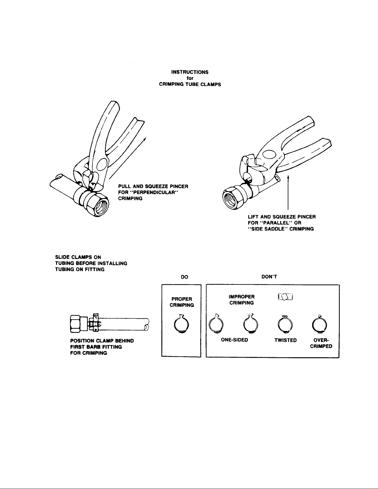
FIGURE 7. INSTRUCTIONS FOR CRIMPING TUBE CLAMPS
19 189159000
Page 24

THIS PAGE LEFT BLANK INTENTIONALLY
20189159000
Page 25
TROUBLESHOOTING
IMPORTANT: Only qualified personnel should service internal components or electrical wiring.
WARNING: If repairs are to be made to carbonated water system, disconnect electrical
power to Cooling Unit, shut off plain water and CO2supplies, and relieve the carbonated
water system pressure before proceeding. If repairs are to be made to syrup system,
remove quick disconnects from applicable syrup tank, then relieve the system pressure before
proceeding. If repairs are to be made to CO2system, stop dispensing, shut off CO2supply , then
relieve the system pressure before proceeding.
If repairs are to be made to an existing Remote Condensing unit, disconnect the power to the
condensing unit before proceeding
Trouble Probable Cause Remedy
NO PRODUCT DISPENSED. A. Product tank quick
disconnects not attached.
B. No product supply (tank
empty).
C. No CO2supply . C. Replenish CO2supply as
DISPENSED PRODUCT
COMES OUT OF
DISPENSING VALVE CLEAR
BUT FOAMS IN CUP OR
GLASS
DISPENSED PRODUCT
FOAMS AS IT LEA VES
DISPENSING VALVE.
A. Oil film or soap scum in cup or
glass.
B. Ice used for finished drink is
sub-- cooled.
NOTE: Crushed ice also causes dispensing problems. When dispensed
drink hits sharp edges of the ice, carbonation is released from drink.
A. Recovery rate of unit
exceeded (ice bank depleted).
B. Product tanks CO2regulator
adjusted too high.
A. Attach quick disconnects.
B. Replenish product supply as
instructed.
instructed.
A. Use clean cups and glasses.
B. Do not use ice directly from
freezer. Allow ice to become ‘‘wet’’
before using. (Refer to following
NOTE)
A. Allow ice bank to recover.
B. Adjust product tanks CO
regulator to proper equilibrium
pressure as instructed, then
replace product supply.
2
C. Dispensing valve restricted or
dirty .
D. Tapered nylon washer inside
tube swivel nut connection
distorted from being
overtightened restricting
product flow.
E. Oil, water, or dirt in CO
supply .
21 189159000
2
C. Clean dispensing valve as
instructed.
D. Replace nylon washer. Make sure
it is properly seated.
E. Remove contaminated CO2.
Clean CO2system (lines,
regulators, etc.). Install a clean
CO2supply .
Page 26

Trouble RemedyProbable Cause
REFRIGERATION SYSTEM
COMPRESSOR DOES NOT
OPERA TE.
A. Ice bank sufficient. A. Refrigeration not called for.
B. Unit power cord unplugged or
unit power switch in ‘‘OFF’’
(down) position.
C. No power source (blown fuse
or tripped circuit breaker).
D. Low voltage at compressor
terminals.
E. Loose, disconnect, or broken
wiring.
F. Overload protector cut out;
over-- heated compressor.
B. Plug in power cord or flip power
switch to ‘‘ON’’ (up) position.
C. Replace fuse or reset circuit
breaker. (Note: Fuse is not part of
unit)
D. V oltage must be at least 103 volts
(1 15 VAC model) or 208 volts
(230 VAC model) at compressor
terminals when compressor is
trying to start.
E. Tighten connections or replace
broken wiring.
F. Compressor will cool enough to
Condenser fan restart. Do not
overdraw cooling motor not
operating as required. capacity of
dispenser. Refer to
‘‘CONDENSER FAN MOTOR
NOT OPERATING’’ in this
section.
COMPRESSOR WILL NOT
STOP AFTER SUFFICIENT
ICE BANK IS FORMED.
(NOTE-- ICE BANK SHOULD
JUST COVER CONTROL
BULB).
COMPRESSOR OPERATES
CONTINUOUSL Y BUT DOES
NOT FORM SUFFICIENT ICE
BANK.
G. Inoperative overload protector
or start relay .
H. Inoperative ice bank control. H. Replace ice bank control.
I. Inoperative compressor. I. Replace compressor.
A. Ice bank control cap tube
kinked or broken.
B. Ice bank control stuck in
closed position.
A. Cooling capacity is exceeded
by over --drawing.
B. Unit located in excessively hot
area or air circulation through
condenser coil is restricted.
C. Refrigeration system leak. C. Repair refrigeration system.
NOTE: Ice bank freezes from bottom of evaporator upward. A
refrigerant leak or insufficient charge might show an ice bank at
bottom and not at top of evaporator.
G. Replace inoperative part.
A. Replace ice bank control.
B. Replace ice bank control.
A. Reduce amount of drinks drawn
per given time.
B. Relocate unit or determine and
correct condenser coil restriction.
22189159000
Page 27

Trouble RemedyProbable Cause
NOTE: If overload protector cuts out compressor, condenser fan motor
will continue to run; otherwise; troubleshooting condenser fan motor
problems is same as for “COMPRESSOR DOES NOT OPERATE”
paragraph plus the following:
CONDENSER FAN MOTOR
NOT OPERATING.
AGITA TOR MOTOR NOT
OPERA TING.
A. Jumper cord loose or
disconnected from motor or
terminal block. Broken wire is
cord.
B. Fan blade obstructed. B. Remove obstructions.
C. Inoperative condenser fan
motor.
A. Unit power cord or agitator
motor power cord
disconnected or unit power
switch in “OFF” position.
B. No power source (blown fuse
or tripped circuit breaker).
C. Agitator motor propeller
obstructed.
D. Low voltage. D. V oltage must be at least 103 volts
E. Loose, disconnected, or
broken wiring.
A. Tighten connections or replace
cord.
C. Replace condenser fan motor.
A. Plug in power cords or place unit
power switch in “ON” position.
B. Replace fuse or reset circuit
breaker. (Note: Fuse is not part of
unit).
C. Remove obstructions.
(1 15 VAC model or 208 volts (230
V AC model) at compressor
terminals when compressor is
trying to start.
E. Tighten connections or replace
broken wiring.
F. Inoperative agitator motor. F. Replace agitator motor as
instructed.
23 189159000
Page 28

WARRANTY
IMI Cornelius Inc. warrants that all equipment and parts are free from defects in material and workmanship under normal use and service. For a copy of the warranty applicable to your Cornelius, Remcor or
Wilshire product, in your country, please write, fax or telephone the IMI Cornelius office nearest you.
Please provide the equipment model number, serial number and the date of purchase.
IMI Cornelius Offices
AUSTRALIA D P.O. 210, D RIVERWOOD, D NSW 2210, AUSTRALIA D (61) 2 533 3122 D FAX (61) 2 534 2166
AUSTRIA D AM LANGEN FELDE 32 D A-1222 D VIENNA, AUSTRIA D (43) 1 233 520 D FAX (43) 1-2335-2930
BELGIUM D BOSKAPELLEI 122 D B-2930 BRAASCHAAT , BELGIUM D (32) 3 664 0552 D FAX (32) 3 665 2307
BRAZIL D RUA ITAOCARA 97 D TOMAS COELHO D RIO DE JANEIRO, BRAZIL D (55) 21 591 7150 D FAX (55) 21 593 1829
ENGLAND D TYTHING ROAD ALCESTER D WARWICKSHIRE, B49 6 EU, ENGLAND D (44) 789 763 101 D FAX (44) 789 763 644
FRANCE D 71 ROUTE DE ST. DENIS D F-95170 DEUIL LA BARRE D PARIS, FRANCE D (33) 1 34 28 6200 D FAX (33) 1 34 28 6201
GERMANY D CARL LEVERKUS STRASSE 15 D D-4018 LANGENFELD, GERMANY D (49) 2173 7930 D FAX (49) 2173 77 438
GREECE D 488 MESSOGION AVENUE D AGIA PARASKEVI D 153 42 D ATHENS, GREECE D (30) 1 600 1073 D FAX (30) 1 601 2491
HONG KONG D 1104 TAIKOTSUI CENTRE D 11-15 KOK CHEUNG ST D TAIKOKTSUE, HONG KONG D (852) 789 9882 D FAX (852) 391 6222
ITALY D VIA PELLIZZARI 11 D 1-20059 D VIMARCATE, ITALY D (39) 39 608 0817 D FAX (39) 39 608 0814
NEW ZEALAND D 20 LANSFORD CRES. D P.O. BOX 19-044 AVONDALE D AUCKLAND 7, NEW ZEALAND D (64) 9 8200 357 D FAX (64) 9 8200 361
SINGAPORE D 16 TUAS STREET D SINGAPORE 2263 D (65) 862 5542 D FAX (65) 862 5604
SPAIN D POLIGONO INDUSTRAIL D RIERA DEL FONOLLAR D E-08830 SANT BOI DE LLOBREGAT D BARCELONA, SPAIN D (34) 3 640 2839 D FAX (34) 3 654 3379
USA D ONE CORNELIUS PLACE D ANOKA, MINNESOTA D (612) 421-6120 D FAX (612) 422-3255
LD004
4/21/98
24
 Loading...