

Page 1
Owner’s Manual
ICE/BEVERAGE
DISPENSER
TJ400S-K
TJ400S-KB
TJ400S-KBC
Part No. 91700
August, 1995
THIS DOCUMENT CONTAINS IMPORTANT INFORMATION
This Manual must be read and understood before installing or operating this equipment
âREMCOR INC: 1995
PRINTED IN U.S.A
Page 2

TABLE OF CONTENTS
SAFETY PRECAUTIONS 1. . . . . . . . . . . . . . . . . . . . . . . . . . . . . . . . . . . . . . . . . . . . . . . . . . .
DESCRIPTION 2. . . . . . . . . . . . . . . . . . . . . . . . . . . . . . . . . . . . . . . . . . . . . . . . . . . . . . . . . . . .
INSTALLA TION INSTRUCTIONS 3. . . . . . . . . . . . . . . . . . . . . . . . . . . . . . . . . . . . . . . . . . . .
INSTALLING DISPENSER 3. . . . . . . . . . . . . . . . . . . . . . . . . . . . . . . . . . . . . . . . . . . . . .
GATE RESTRICTOR PLATE 4. . . . . . . . . . . . . . . . . . . . . . . . . . . . . . . . . . . . . . . . . . . .
GATE RESTRICTOR PLATE ADJUSTMENT 4. . . . . . . . . . . . . . . . . . . . . . . . . . . . . .
MAINTENANCE 8. . . . . . . . . . . . . . . . . . . . . . . . . . . . . . . . . . . . . . . . . . . . . . . . . . . . . . . . . . .
START-UP AND OPERATING INSTRUCTIONS 8. . . . . . . . . . . . . . . . . . . . . . . . . . .
CLEANING 8. . . . . . . . . . . . . . . . . . . . . . . . . . . . . . . . . . . . . . . . . . . . . . . . . . . . . . . . . . . .
DISPENSER 8. . . . . . . . . . . . . . . . . . . . . . . . . . . . . . . . . . . . . . . . . . . . . . . . . . . . . . . . .
COLD PLATE 9. . . . . . . . . . . . . . . . . . . . . . . . . . . . . . . . . . . . . . . . . . . . . . . . . . . . . . . .
BEVERAGE SYSTEM (B, BC MODELS) 9. . . . . . . . . . . . . . . . . . . . . . . . . . . . . . . .
TROUBLESHOOTING GUIDE 11. . . . . . . . . . . . . . . . . . . . . . . . . . . . . . . . . . . . . . . . . . . . . . .
BLOWN FUSE OR CIRCUIT BREAKER 11. . . . . . . . . . . . . . . . . . . . . . . . . . . . . . . . . .
GATE DOES NOT OPEN. 11. . . . . . . . . . . . . . . . . . . . . . . . . . . . . . . . . . . . . . . . . . . . . . .
GATE DOES NOT OPEN OR IS SLUGGISH. AGITATOR TURNS. 11. . . . . . . . . . .
GATE OPENS. AGITATOR DOES NOT TURN. 11. . . . . . . . . . . . . . . . . . . . . . . . . . . .
ICE DISPENSES CONTINUOUSLY. 11. . . . . . . . . . . . . . . . . . . . . . . . . . . . . . . . . . . . . .
SLUSHY ICE. WATER IN HOPPER. 11......................................
BEVERAGE DOES NOT DISPENSE 11. . . . . . . . . . . . . . . . . . . . . . . . . . . . . . . . . . . . .
BEVERAGES TOO SWEET 12. . . . . . . . . . . . . . . . . . . . . . . . . . . . . . . . . . . . . . . . . . . . .
BEVERAGES NOT SWEET ENOUGH 12. . . . . . . . . . . . . . . . . . . . . . . . . . . . . . . . . . . .
BEVERAGES NOT COLD (UNITS WITH BUILT-IN COLD PLATE). 12. . . . . . . . . . .
SOLENOID ASSEMBLY PARTS LIST 14. . . . . . . . . . . . . . . . . . . . . . . . . . . . . . . . . . . . . . . .
Page
PARTS LIST 15. . . . . . . . . . . . . . . . . . . . . . . . . . . . . . . . . . . . . . . . . . . . . . . . . . . . . . . . . . . . . .
WARRANTY 17..............................................................
LIST OF FIGURES
FIGURE 1. GATE RESTRICTOR PLATE ADJUSTMENT 4. . . . . . . . . . . . . . . . . . . .
FIGURE 2. MOUNTING TEMPLATE 5. . . . . . . . . . . . . . . . . . . . . . . . . . . . . . . . . . . . .
FIGURE 3. BEVERAGE SYSTEM SCHEMATIC (“B” MODELS) 6. . . . . . . . . . . . . .
FIGURE 4. BEVERAGE SYSTEM SCHEMATIC (“BC” MODELS) 7. . . . . . . . . . . .
FIGURE 5. WIRING DIAGRAM 13. . . . . . . . . . . . . . . . . . . . . . . . . . . . . . . . . . . . . . . . . .
FIGURE 6. SOLENOID ASSEMBLY EXPLODED VIEW AND PARTS LIST 14. . . .
FIGURE 7. DISPENSING LEVERS AND SWITCHES 16. . . . . . . . . . . . . . . . . . . . . . .
LIST OF TABLES
TABLE 1. SPECIFICATIONS 2. . . . . . . . . . . . . . . . . . . . . . . . . . . . . . . . . . . . . . . . . . . .
i
91700
Page 3
SAFETY PRECAUTIONS
ALWAYS: Disconnect power to the dispenser before servicing or cleaning.
NEVER: Place hands inside of hopper or gate area without disconnecting power to the dispenser. Agitator
rotation occurs automatically when dispenser is energized!
This ice dispenser has been specifically designed to provide protection against personal injury and eliminates
contamination of ice. To ensure continued protection and sanitation, observe the following:
ALWAYS: Be sure removable lid is properly installed to prevent unauthorized access to the hopper
interior and possible contamination of the ice.
ALWAYS: Be sure the upper and lower front panels are securely fastened.
ALWAYS: Keep area around the dispenser clean of ice cubes.
Dispenser cannot be used with crushed or flaked ice.
Use of bagged ice that has frozen into large chunks can void warranty . The dispenser
agitator is not designed to be an ice crusher. Use of large chunks of ice that “jam up”
inside the hopper will cause failure of the agitator motor and damage to the hopper. If bagged ice
is used, it must be carefully and completely broken into small, cube-sized pieces before filling into
the dispenser hopper.
917001
Page 4

DESCRIPTION
The TJ400 series ice dispensers solve your ice and beverage service needs in a sanitary , space saving,
economical way . Designed to be manually filled with ice from any remote ice-making source, these dispensers
will dispense cubes (up to 1-1/4 inch in size), cubelets and hard-chipped or cracked ice; and in addition, several
flavors of post-mix beverages. “B” models contain beverage faucets only , and must be supplied cold product
from any remote cold plate or refrigerated soda factory . “BC” units include beverage faucets and a cold plate
and are designed to be supplied direct from syrup tanks and carbonator; with no additional cooling required.
S=Stainless Steel Cabinetry .
K=Provided with top cover/frame for supporting ice maker.
B=Beverage dispenser.
BC=Beverage and Cold Plate System.
Table 1. Specifications
Model: TJ400 (K, KB, and KBC)
Ice Storage: 400 pounds
Maximum No. of Beverage Valves Available: 16
Built-in Cold Plate: Optional (KBC Model Only)
Electrical:
Voltage: 115/1/60
Amperage: 7.0 Amps
Dimensions:
Width: 48 inches
Depth: 36 inches
Height: 47-3/16 inches
Drain Connection: 7/8 inch
91700 2
Page 5

INSTALLATION INSTRUCTIONS
INSTALLING DISPENSER
1. The ice dispenser must be sealed to the counter. The template drawings (page 5) indicate openings that
must be cut in the counter. Locate the desired position for the dispenser, then mark the outline
dimensions and cut out locations using the template drawing. Cut openings in the counter.
Apply a continuous bead of NSF International (NSF) approved silastic sealant (Dow 732 or equal) approximately 1/4 inch inside of the unit outline dimensions and all around openings. Then, position the unit on the
counter within the outline dimensions. All excess sealant must be wiped off immediately.
2. Carefully pull beverage tubes, drain line, and power cord through the large openings in the bottom of the
unit. See mounting template (Figure 2) for locating the required clearance holes in the counter for these
utility lines.
3. Install the ice maker according to instructions supplied with the installation kit (consult factory for kit part
numbers), manufacturer’s instructions supplied with ice maker.
4. Connect the drain tube to an open drain. If additional piping is required, it must be 3/4? IPS (or equal), and
must pitch downward away from the unit for proper drainage.
5. Connect the beverage system product lines according to the system schematics shown on page 6 for “B”
Models and page 7 for “BC” Models. This work should be done by a qualified service person. Consult with
your local syrup or beverage equipment supplier for recommended practices for system hook-up.
IMPORTANT: Potable water supplied to the dispenser must comply with the Basic Plumbing Code of
the Building Officials and Code Administrators International, Inc. (BOCA).
6. Clean the storage hopper interior (see Cleaning Instructions on page 8).
7. Connect the power cord to a 115 volt, 60 cycle, 3-wire grounded receptacle. If local code requires the unit
to be permanently wired, the power supply cord can be disconnected from the machine’s internal wiring
(2 wire nuts) and the electrical control box (clamp-style strain relief fitting). The control box is located in the
upper right corner at the front of the unit. Access is provided by removing the upper front cabinet
panel. With the power cord removed, conduit can then be routed from the rear of the unit, inside the lower
compartment and up to the control box. Electrical wiring must comply with national and local electrical
codes.
NOTE: Water pipe connections and fixtures directly connected to a potable water supply shall be sized,
installed and maintained according to Federal, State, and Local Laws.
917003
Page 6
GATE RESTRICTOR PLATE
CAUTION: Disconnect power to dispenser before installing, removing, or adjusting
restrictor.
INSTALL PLATE ON
STUDS AS SHOWN
ADJUSTMENT
FIGURE 1. GA TE RESTRICTOR PLATE ADJUSTMENT
ADJUSTMENT
This dispenser is provided with a gate restrictor plate, installed in it’s highest position. This plate adjusts the rate
of ice flow from the dispenser. In applications using buckets, carafes, or other large containers, the plate may be
removed entirely for maximum ice flow. For glasses and cups, the plate may be adjusted downward to
reduce the flow of ice. The best position depends on the type of ice being used and the size container and must
be found by trial and error. Adjustment is made by loosening the upper two ice chute retaining nuts, sliding the
restrictor plate to the desired position and re-tightening the nuts.
If the dispenser fails to dispense the ice when operated, check that the hopper has ice in it and that power is
being supplied to the unit. If problems persist, check the following:
1. Determine if the agitator is rotating (check for the sound of ice movement in the hopper).
2. Observe if the gate is opening.
91700 4
Page 7

13 31/32-IN. 13 31/32-IN.7 25/32-IN. 3 15/16-IN.
25/32-IN.
3 17/32-IN.
2 3/4-IN.
OUTLINE
OF UNIT
5 7/32-IN.
20 13/32-IN.2 3/4-IN.
36-IN.
FRONT
48-IN.
NOTE: SHADED AREAS INDICATE OPENINGS IN CABINET BOTTOM
NEEDED FOR BEVERAGE TUBING AND UTILITIES.
FIGURE 2. MOUNTING TEMPLA TE
917005
Page 8

CO2 TANK
WATER
SUPPLY
SYRUP TANKS
REGULATORS
S10 S11 S12
60-100 PSIG
15-50 PSIG
OPTIONAL FOR
DIET OR ROOT BEER
S1 S2 S3 S4 S5 S6 S7 S8 S9
REGULATOR
OPTIONAL PRESSURE
FILTER
CARBONATOR
DOUBLE CHECK VALVE
5-15 PSIG
1
2
3
4
5
6
ICE BANK
COLD PLATE OR
REFRIGERATED
FAUCETS
REMCOR “B” ICE/BEVERAGE DISPENSER
ITEMS OUTSIDE OF BROKEN LINES NOT
FIGURE 3. BEVERAGE SYSTEM SCHEMA TIC (“B” MODELS)
91700 6
7
8
9
INCLUDED WITH UNIT
CW
CW
10
11
12
Page 9

CO2 TANK
“
WATER
SUPPLY
REGULATORS
SYRUP TANKS
REGULATOR
OPTIONAL PRESSURE
FILTER
60-100 PSIG
15-50 PSIG
S1 S2 S3 S4 S5 S6
CARBONATOR
OPTIONAL FOR
DIET OR ROOT BEER
5-15 PSIG
1
2
3
4
5
ICE BANK
COLD PLATE OR
REFRIGERATED
FAUCETS
6
DOUBLE CHECK VALVE
CW
CW
INCLUDED WITH UNIT
REMCOR “BC”ICE/BEVERAGE DISPENSER
ITEMS OUTSIDE OF BROKEN LINES NOT
FIGURE 4. BEVERAGE SYSTEM SCHEMA TIC (“BC” MODELS)
917007
Page 10

MAINTENANCE
The following dispenser maintenance should be performed at the intervals indicated.
DAILY: (or as required)--Remove foreign material from vending area sink to prevent drain blockage.
WEEKLY: (or as required)--Clean vending area. Check for proper water drainage from the vending area sink.
MONTHLY: (or as required)--Clean and sanitize the hopper interior (beverage valves and cold plate on KB and
KBC models). see CLEANING INSTRUCTIONS ON PAGE 8.
START-UP AND OPERATING INSTRUCTIONS
Fill the hopper with ice. With a built-in cold plate (KBC models only), dispense several large cups of ice (approximately 1 minute total dispensing time) to allow ice to agitate and fill the cold plate. Add ice to the hopper as necessary to refill and replace the lid. Allow 10 to 15 minutes for the cold plate to cool down. Repeat this procedure
whenever the dispenser has been standing overnight or other long periods without ice use. Start up the beverage system and adjust faucets to the proper brix. Contact your local syrup distributor for complete
information on the beverage system.
In normal operation, pushing the ice dispenser lever will cause ice to flow from the ice chute. Ice flow will continue until the lever is released. Pushing the lever or button on any faucet will provide beverage of the appropriate
flavor.
NOTE: Use caution to avoid spilling ice when filling dispenser. Clean up immediately any spilled ice
from filling or operating the unit. To prevent contamination of ice, the lid must be installed on the unit
at all times.
CLEANING
WARNING: DISCONNECT POWER BEFORE CLEANING. Do not use metal scrapers, sharp
objects, or abrasives on the ice storage hopper as damage may result. Do not use solvents
or other cleaning agents as they may attack the plastic liner.
DISPENSER
1. Clean the ice storage hopper at least once a month.
2. Remove the top lid and lift out the agitator.
3. Wash the agitator in a detergent solution and rinse thoroughly to remove all traces of detergent.
4. Wash down the inside of the hopper and top cover with a mild detergent solution, and rinse thoroughly to
remove all traces of detergent.
5. Replace agitator.
6. Sanitize agitator and all internal surfaces of the hopper with a solution of 1 ounce of household bleach in 2
gallons of water (200 PPM).
91700
8
Page 11

7. Remove ice chute cover as follows:
A. Flex sides outward to disengage lower pins.
B. Lift ice chute cover to disengage upper pins.
C. Lower ice chute cover down out of unit. NOTE: It may be helpful to twist cover slightly.
8. Clean the inside of the ice transfer conduits, ice chute covers, and ice chutes with a mild detergent solution
and rinse thoroughly to remove all traces of detergent.
9. Reverse steps above to reassemble ice chute.
10. Sanitize as described in preceding step 6.
COLD PLATE
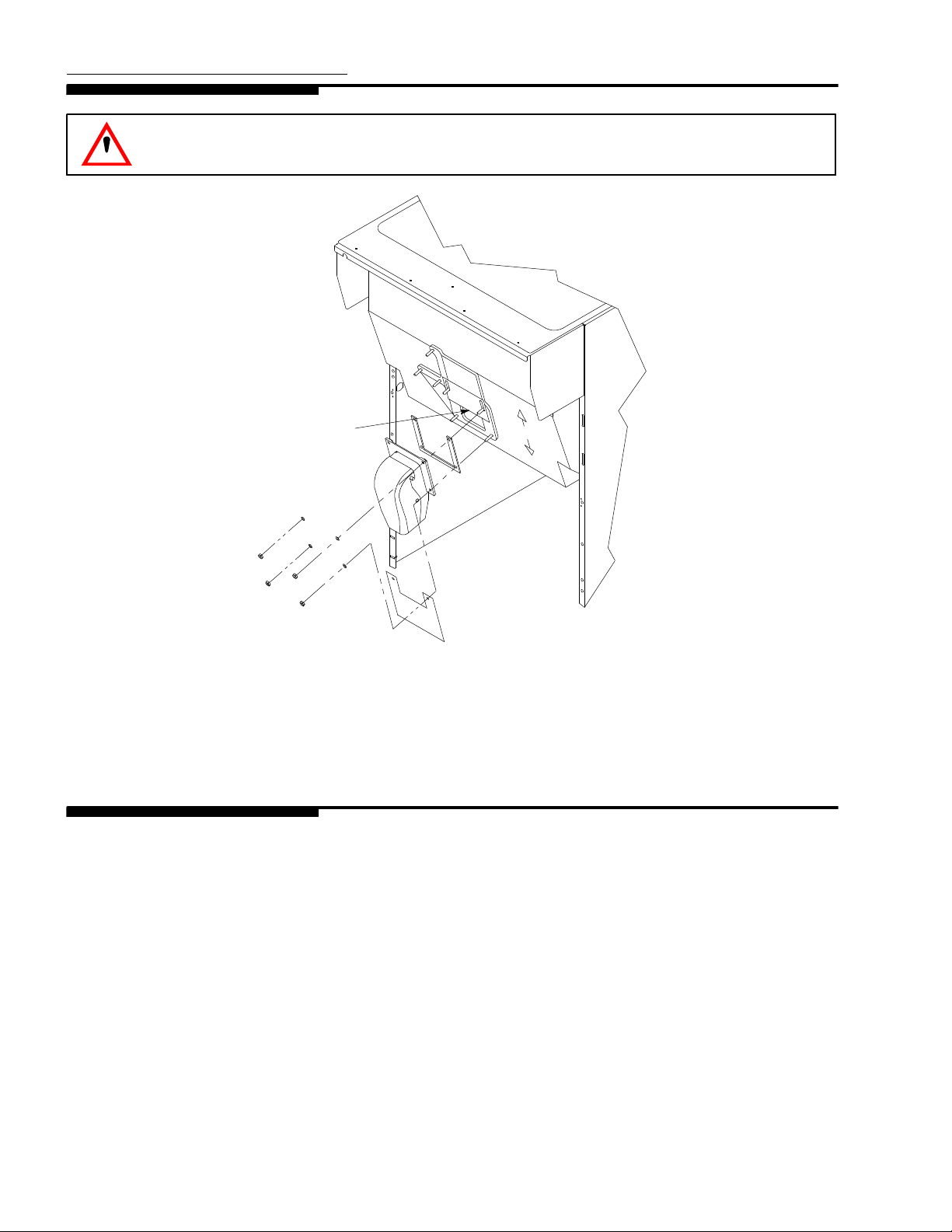
1. Carefully remove the lower front panel of the ice dispenser.
2. Remove cold plate cover by lifting slightly in front and slide forward.
3. Wash down the inside of the cold plate and cover with mild detergent solution and rinse. A small long handled brush will be found helpful in reaching the corners.
4. Replace the cover, taking care that it is securely positioned in the cold plate tray.
5. Replace the lower front panel, carefully feeding the tubing and wires into the cabinet. Be sure not to pinch
any tubing or wires between the panel and cabinet.
BEVERAGE SYSTEM (B, BC MODELS)
1. Remove faucet spouts, wash in mild detergent, rinse and replace.
2. Disconnect electrical power to the carbonator. Shut off the water supply and close the CO2regulator to the
carbonator.
3. Disconnect the syrup tanks from the system.
4. Energize the beverage faucets to purge the remaining soda water in the system.
5. Use a 5 gallon tank for each of the following:
A. Cleaning Tank: Fill with hot (120° F-140° F) potable water.
B. Sanitation Tank: Fill with a chlorine sanitizing solution in the strength of 1 ounce of household bleach
(sodium hypochlorite) to 2 gallons of cold (ambient) potable water (200 PPM).
6. Repeat the following procedure on each of the unit’s syrup product lines:
A. Connect the cleaning tank to the syrup line to be sanitized and to the CO2system.
B. Energize the beverage faucet until the liquid dispensed is free of syrup.
C. Disconnect the cleaning tank and hook up the sanitizing tank to the syrup line and CO2system.
D. Energize the beverage faucet until the chlorine sanitizing solution is dispensed through the faucet.
Flush at least 2 cups of liquid to ensure that the sanitizing solution has filled the entire length of the
syrup line. Allow sanitizer to remain in the system for 20 minutes.
917009
Page 12

E. Disconnect the sanitizing tank. Hook up the product tank to the syrup line and to the CO2system.
F. Energize the faucet to flush the sanitizing solution from the syrup line and faucet. Continue draw on
the faucet until only syrup is dispensed.
7. Repeat preceding step 2 in reverse order to turn on the carbonator. Dispense at least 1 cup of beverage
from each faucet. Check taste. Continue to flush, if needed, to obtain a satisfactory tasting drink.
91700
10
Page 13

TROUBLESHOOTING GUIDE
Should your unit fail to operate properly , check that there is power to the unit and that the hopper contains ice.
If the unit does not dispense, check the following table under the appropriate symptoms to aid in locating the
defect.
Trouble Probable Cause Remedy
BLOWN FUSE OR CIRCUIT
BREAKER.
GATE DOES NOT OPEN. A. No power. A. Restore power.
GATE DOES NOT OPEN OR
IS SLUGGISH. AGITATOR
TURNS.
GATE OPENS. AGITATOR
DOES NOT TURN.
A. Short circuit in wiring. A. Repair wiring.
B. Defective gate solenoid coil. B. Replace solenoid coil.
C. Defective agitator motor. C. Replace agitator motor.
B. Bent depressor plate (does not
actuate switch).
C. Defective dispensing switch. C. Replace dispensing switch.
D. Blown/defective fuse or
jammed gate solenoid.
A. Defective gate solenoid coil. A. Replace gate solenoid coil.
B. Weak gate spring. B. Replace gate spring.
C. Excessive pressure against
gate slide.
A. Ice solidified in hopper. A. Break ice up in hopper.
B. Defective agitator motor. B. Replace agitator motor.
B. Replace depressor plate.
D. Replace fuse or replace gate
solenoid coil.
C. Reduce pressure on gate slide.
ICE DISPENSES
CONTINUOUSLY.
SLUSHY ICE. WATER IN
HOPPER.
BEVERAGE DOES NOT
DISPENSE.
C. Defective capacitor. C. Replace capacitor.
D. BC models only: defective
agitation timer.
A. Stuck or bent depressor plate
(does not release switch).
B. Defective dispensing switch. B. Replace dispensing switch.
C. Improper switch installation. C. Install switch properly.
A. Blocked drain. A. Open drain.
B. Unit not level. B. Level the unit.
C. Poor ice quality due to water
quality or ice maker problems.
D. Improper use of flaked ice. D. Do not use flaked ice.
A. No 24 volts to faucets. A. Restore 24 volts to faucets.
B. No CO2pressure. B. Restore CO2pressure.
11
D. Replace agitation timer.
A. Replace depressor plate.
C. Improve water quality or repair
ice maker problems.
91700
Page 14

Trouble RemedyProbable Cause
BEVERAGES TOO SWEET. A. Carbonator not working. A. Repair carbonator.
B. No CO2pressure in
carbonator.
B. Restore CO2pressure to
carbonator.
C. Faucet brix requires adjusting. C. Adjust faucet brix.
BEVERAGES NOT SWEET
A. Empty syrup tank. A. Replenish syrup supply.
ENOUGH.
B. Faucet brix requires adjusting. B. Adjust faucet brix.
BEVERAGES NOT COLD
(UNITS WITH BUILT-IN COLD
PLATE).
A. Unit standing with no ice in
hopper--no ice in cold plate
cabinet.
A. Replenish ice supply .
Contact your local syrup or beverage equipment distributor for additional information and troubleshooting of the
beverage system. Refer to the Manufacturer’s instructions for troubleshooting the ice maker.
91700
12
Page 15

ICE LEVEL SIGNAL
OPTION
LIGHTT’STAT
WHT
BLK
COLD PLATE
MOTOR OPTION
24 V.
KEY
SWITCH
OPTION
BEVERAGE SYSTEM
PORTION
CONTROL
OPTION
WHT
TO
N
TO
A
TO
L
WHT
CAP
WHT
BLK
TRANSFORMER
BEVERAGE
FAUCET
(TYPICAL)
PORTION
TIMER
TD
RED
BRN
MOTOR
HEATER
BLK
SW
OR
YEL
DISPENSE
SWITCH
BLK
TERMINAL
BOARD
BLK
BRN
WHT
WHT
NL
DISPENSE
SWITCH
GRNNL
YEL
RED
WHT
BLK
WHT
RED
WHT
BLK
LIGHTED DISPLAY
OPTION
BALLAST
LIGHT
LIGHT
GATE
SOLENOID
1 1/4 AMP TIME
DELAY FUSE
AGITATION TIMER
C
NO
NC
BLUE
YEL
AGITATOR
MOTOR
AGITATOR
MOTOR RELAY
SERVICE INFORMATION
DANGER!
ELECTRIC SHOCK HAZARD. DISCONNECT
POWER BEFORE SERVICING UNIT.
7
8
SOLENOID
ADJUSTMENT
WHEN REPLACING SOLENOID,
ADJUST TO 7/8 AS SHOWN
BEFORE TIGHTENING
MOUNTING SCREWS.
FIGURE 5. WIRING DIAGRAM
13 91700
Page 16

22
17
19
22
4
1
4
18
21
16
15
14
19
13
9
2
3
5
22
20
6
8
11
10
12
7
FIGURE 6. SOLENOID ASSEMBLY -- EXPLODED VIEW AND PARTS LIST
Index
No.
1 21493 1 Solenoid Mounting Plate
2# 31551 1 Solenoid Service Kit
3 70171 2 8--32 x 3/8 Phil Tr HD Screw
4 70121 2 No. 8 Lockwasher
5 50752 3 Isolator
6* 50789 2 Bumper Assembly
7* 70423 1 Cotter Pin
8* 10080 1 Gate Lift Rod
9 10081 1 Gate Lift Rod Bushing
10 50754 1 Gate Arm Bearing
11 21492 1 Gate Lift Arm
12 70043 1 Flatwasher
13* 70422 1 Spring
14 70263 1 1/4-20 x 3/4 Hex Hd Screw
15 70048 1 1/4 Lockwasher
16 70066 1 1/4 Flatwasher
17 10077 1 Pivot Bearing
18 30227 1 1/4 Quick Connect Tab
19 50305 ---- Lubricant
20* 21592 1 Solenoid Linkage Pin
21* 70433 2 Retainer Ring
22 51088 ---- Loctite
----* 70438 ---- Rebuilding Kit
Part No. Qty . Name
NOTE: * Parts supplied with rebuilding kit.
# 31551 solenoid supplied with items 20 & 21.
91700
14
Page 17

PARTS LIST
Index
DESCRIPTION PART NO.
No.
1 Depressor Retainer (for 22777) 22644
2 Depressor Lever (Cup Activated)* 22777
3 Depressor Push Lever * 27472
4 Dispensing Switch 30895
5 Mercury Relay (Agitator Motor) 31375
6 Timer, Agitation 31763
7 Fuse, Gate Solenoid 31406
8 Terminal Board 30960
9 Switch Boot 31007
10 Transformer (2), Beverage Faucet 32682
11 Agitator Motor 31617
12 Agitator Motor Heater 30794
13 Sink Grill 70515
14 Sink 51113
15 Motor Shaft Seal 51101
16 Insulation (Agitator Motor) 50967
17 Gate Gasket 51891
18 Gate Slide 21491
19 Ice Chute (Back Section) 53015
20 Ice Chute Cover 53016
21 Ice Chute Extension * 52178
22 Solenoid (see page 14) 31551
23 Rebuilding Kit 70438
24 Agitator 23102
25 Lid Assembly (removable) 23086
26 Cover Assembly 23462
27 Ice Chute Extension Mtg. Brkt. * 28218
Options *
Beverage Faucets (--KB, and --KBC Models)
Lancer, Push Button 41050
Lancer, Push Button with Soda Lever 41037
McCann’s, Fast Flow -- Lever 40444
McCann’s, Fast Flow -- PB 40790
Cornelius, CC1 41181
Cornelius, SF1 -- PB (1.5 to 3 oz.) 40756
Cornelius, SF1 Lever (1.5 to 3 oz.) 40445
Wilshire, Fast Flow (Dole) -- PB 40730
Wilshire, Fast Flow (Dole) -- Lever 40483
Cornelius, UFF -- Lever (1.5 to 3 oz) 41368
Cornelius, UHF -- PB (1.5 to 3 oz) 41369
Cornelius, UFF -- Lever (3 to 4.5 oz) 41334
Cornelius, UHF -- PB (3 to 4.5 oz) 41335
15 91700
Page 18

CUP ACTIVATED
1
PUSH LEVER
3
9
2
9
4
4
91700
1
FIGURE 7. DISPENSING LEVERS AND SWITCHES
16
Page 19

REMCOR PRODUCT COMPANY
500 Regency Drive
Glendale Heights, IL60139-2268
Telephone(708) 980--6900
Facsimile (708) 980--8511
WARRANTY
REMCOR warrants that all equipment and parts are free from defects in material and workmanship under normal use and service. For a copy of the warranty applicable to your REMCOR product, in your country ,please
write, fax or telephone the IMI Cornelius office nearest you. Please provide the equipment model number and
the date of purchase.
IMI Cornelius Offices
AUSTRALIA D P.O. 210, D RIVERWOOD, D NSW 2210, AUSTRALIA D (61) 2 533 3122 D FAX (61) 2 534 2166
AUSTRIA D AM LANGEN FELDE 32 D A-1222 D VIENNA, AUSTRIA D (43) 1 233 520 D FAX (43) 1-2335-2930
BELGIUM D BOSKAPELLEI 122 D B-2930 BRAASCHAAT, BELGIUM D (32) 3 664 0552 D FAX (32) 3 665 2307
BRAZIL D RUA ITAOCARA 97 D TOMAS COELHO D RIO DE JANEIRO, BRAZIL D (55) 21 591 7150 D FAX (55) 21 593 1829
ENGLAND D TYTHING ROAD ALCESTER D WARWICKSHIRE, B49 6 EU, ENGLAND D (44) 789 763 101 D FAX (44) 789 763 644
FRANCE D 71 ROUTE DE ST. DENIS D F-95170 DEUIL LA BARRE D PARIS, FRANCE D (33) 1 34 28 6200 D FAX (33) 1 34 28 6201
GERMANY D CARL LEVERKUS STRASSE 15 D D-4018 LANGENFELD, WEST GERMANY D (49) 2173 7930 D FAX (49) 2173 77 438
GREECE D 488 MESSOGION AVENUE D AGIA PARASKEVI D 153 42 D ATHENS, GREECE D (30) 1 600 1073 D FAX (30) 1 601 2491
HONG KONG D 1104 TAIKOTSUI CENTRE D 11-15 KOK CHEUNG ST D TAIKOKTSUE, HONG KONG D (852) 789 9882 D FAX (852) 391 6222
ITALY D VIA PELLIZZARI 11 D 1-20059 D VIMARCATE, ITALY D (39) 39 608 0817 D FAX (39) 39 608 0814
NEW ZEALAND D 20 LANSFORD CRES. D P.O. BOX 19-044 AVONDALE D AUCKLAND 7, NEW ZEALAND D (64) 9 8200 357 D FAX (64) 9 8200 361
SINGAPORE D 16 TUAS STREET D SINGAPORE 2263 D (65) 862 5542 D FAX (65) 862 5604
SPAIN D POLIGONO INDUSTRAIL D RIERA DEL FONOLLAR D E-08830 SANT BOI DE LLOBREGAT D BARCELONA, SPAIN D (34) 3 640 2839 D FAX (34) 3 654 3379
USA D ONE CORNELIUS PLACE D ANOKA, MINNESOTA D (612) 421-6120 D FAX (612) 422-3255
17 91700
Page 20

CORPORATE HEADQUARTERS:
Glendale Heights, IL 60139
Remcor Incorporated
500 Regency Drive
708. 980.6900
 Loading...