

Page 1
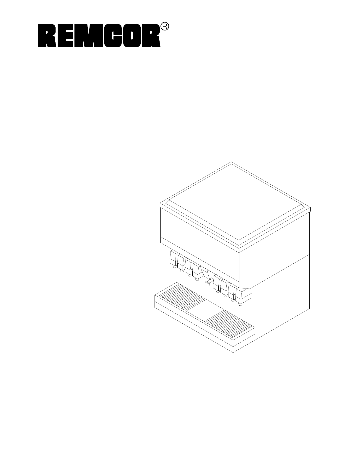
ICE/BEVERAGE DISPENSERS
MODELS: TJ150-B
Operator’s Manual
TJ150-KB
TJ150-BC
TJ150-KBC
Part No. 91803
February , 1997
Revision D
THIS DOCUMENT CONTAINS IMPORTANT INFORMATION
This Manual must be read and understood before installing or operating this equipment
âREMCOR INC:
PRINTED IN U.S.A
Page 2

TABLE OF CONTENTS
SAFETY PRECAUTIONS 1. . . . . . . . . . . . . . . . . . . . . . . . . . . . . . . . . . . . . . . . . . . . . . . . . . .
GENERAL DESCRIPTION 1. . . . . . . . . . . . . . . . . . . . . . . . . . . . . . . . . . . . . . . . . . . . . . . . . .
ICE MAKER 2. . . . . . . . . . . . . . . . . . . . . . . . . . . . . . . . . . . . . . . . . . . . . . . . . . . . . . . . . . .
INSTALLA TION INSTRUCTIONS 3. . . . . . . . . . . . . . . . . . . . . . . . . . . . . . . . . . . . . . . . . . . .
SINK DRAIN ASSEMBLY INSTRUCTIONS 3. . . . . . . . . . . . . . . . . . . . . . . . . . . . . . . .
CLEANING INSTRUCTIONS 4. . . . . . . . . . . . . . . . . . . . . . . . . . . . . . . . . . . . . . . . . . . . . . . .
DISPENSER 4. . . . . . . . . . . . . . . . . . . . . . . . . . . . . . . . . . . . . . . . . . . . . . . . . . . . . . . . . .
COLD PLATE 4. . . . . . . . . . . . . . . . . . . . . . . . . . . . . . . . . . . . . . . . . . . . . . . . . . . . . . . . .
BEVERAGE SYSTEM 5..................................................
MAINTENANCE 6. . . . . . . . . . . . . . . . . . . . . . . . . . . . . . . . . . . . . . . . . . . . . . . . . . . . . . . . . . .
DAILY OR AS REQUIRED 6. . . . . . . . . . . . . . . . . . . . . . . . . . . . . . . . . . . . . . . . . . . . . .
WEEKLY OR AS REQUIRED 6. . . . . . . . . . . . . . . . . . . . . . . . . . . . . . . . . . . . . . . . . . . .
MONTHLY 6. . . . . . . . . . . . . . . . . . . . . . . . . . . . . . . . . . . . . . . . . . . . . . . . . . . . . . . . . . . .
OPERATING INSTRUCTIONS 6. . . . . . . . . . . . . . . . . . . . . . . . . . . . . . . . . . . . . . . . . .
GATE RESTRICTOR PLATE 7. . . . . . . . . . . . . . . . . . . . . . . . . . . . . . . . . . . . . . . . . . . .
ADJUSTMENT 7. . . . . . . . . . . . . . . . . . . . . . . . . . . . . . . . . . . . . . . . . . . . . . . . . . . . . . . .
TROUBLESHOOTING GUIDE 8. . . . . . . . . . . . . . . . . . . . . . . . . . . . . . . . . . . . . . . . . . . . . . .
Page
BLOWN FUSE OR CIRCUIT BREAKER 8. . . . . . . . . . . . . . . . . . . . . . . . . . . . . . . . . .
GATE DOES NOT OPEN. AGITATOR DOES NOT TURN 8. . . . . . . . . . . . . . . . . . .
GATE DOES NOT OPEN OR IS SLUGGISH. AGITATOR TURNS. 8. . . . . . . . . . .
GATE OPENS. AGITATOR DOES NOT TURN. 8. . . . . . . . . . . . . . . . . . . . . . . . . . . .
ICE DISPENSES CONTINUOUSLY. 8. . . . . . . . . . . . . . . . . . . . . . . . . . . . . . . . . . . . . .
SLUSHY ICE. WATER IN HOPPER. 8......................................
ICE SOLIDIFIED IN HOPPER OR ICE AT REAR CORNER ONLY. 8...........
NO ICE IN HOPPER 8. . . . . . . . . . . . . . . . . . . . . . . . . . . . . . . . . . . . . . . . . . . . . . . . . . .
ICE PACKED IN HOPPER 8. . . . . . . . . . . . . . . . . . . . . . . . . . . . . . . . . . . . . . . . . . . . . .
BEVERAGES DO NOT DISPENSE 8. . . . . . . . . . . . . . . . . . . . . . . . . . . . . . . . . . . . . .
BEVERAGES TOO SWEET. 8. . . . . . . . . . . . . . . . . . . . . . . . . . . . . . . . . . . . . . . . . . . .
BEVERAGES NOT SWEET ENOUGH. 8. . . . . . . . . . . . . . . . . . . . . . . . . . . . . . . . . . .
BEVERAGES NOT COLD (UNITS WITH BUILT-IN COLD PLATE). 8. . . . . . . . . . .
FINAL ASSEMBLY PARTS LIST 16. . . . . . . . . . . . . . . . . . . . . . . . . . . . . . . . . . . . . . . . . . . .
WARRANTY 18. . . . . . . . . . . . . . . . . . . . . . . . . . . . . . . . . . . . . . . . . . . . . . . . . . . . . . . . . . . . . .
i
91803
Page 3

TABLE OF CONTENTS (cont’d)
LIST OF FIGURES
FIGURE 1. SINK DRAIN ASSEMBLY 3. . . . . . . . . . . . . . . . . . . . . . . . . . . . . . . . . . . . .
FIGURE 2. GATE RESTRICTOR PLATE 7. . . . . . . . . . . . . . . . . . . . . . . . . . . . . . . . . .
FIGURE 3. TJ150-K ICE CUBER INSTALLATION 9. . . . . . . . . . . . . . . . . . . . . . . . .
FIGURE 4. MOUNTING TEMPLATE TJ150-B, BC 10. . . . . . . . . . . . . . . . . . . . . . . . .
FIGURE 5. SPECIFICATION DRAWING TJ150-B, BC 11. . . . . . . . . . . . . . . . . . . . . .
FIGURE 6. BEVERAGE SYSTEM SCHEMATIC “-B” MODELS 12. . . . . . . . . . . . . .
FIGURE 7. BEVERAGE SYSTEM SCHEMATIC “-BC” MODELS 13. . . . . . . . . . . . .
FIGURE 8. WIRING DIAGRAM TJ150-BC DISPENSER 14. . . . . . . . . . . . . . . . . . . .
FIGURE 9. FINAL ASSEMBLY 15. . . . . . . . . . . . . . . . . . . . . . . . . . . . . . . . . . . . . . . . . .
FIGURE 10. SOLENOID ASSEMBLY -- EXPLODED VIEW AND PAR TS LIST 17.
LIST OF TABLES
TABLE 1. SPECIFICATIONS 1. . . . . . . . . . . . . . . . . . . . . . . . . . . . . . . . . . . . . . . . . . . .
TABLE 2. ICE MAKER/MODEL SERIES 2. . . . . . . . . . . . . . . . . . . . . . . . . . . . . . . . . .
Page
Manufactured Under One or More of the Following Patent Numbers:
3,211,336, 3,274,792, 3,393,839, 3,517,860, 3,739,842, 4,215,803, 4,227,377, 4,300,3594,346,824
Canadian Patent Numbers912,514 (10/72), 936,855 (11,73), 4,429,543, 4,921,149
Other Patents Pending
91803
Page 4
SAFETY PRECAUTIONS
This ice dispenser has been specifically designed to provide protection against personal injury and eliminate
contamination of ice. To ensure continued protection and sanit ation, observe the following:
Always d isconnect power to th e dispenser before servicing or cleaning.
Never place han ds inside of ho pper or gate area without disconnecting power to the dispenser. Agitator rotation
occurs automa tically when the dispenser is energized!
ALWAYS be sure the removable lid is properly installed to prevent unauthorized access to the hopper interior and possible contamination of ice.
ALWAYS be sure the upper and lower front panels are securely fastened.
ALWAYS keep area around the dispenser clean of ice cubes.
CAUTION: Dispenser cannot be used with crushed or flaked ice.
Use of bagged ice which has frozen into large chunks can void warranty. The dispenser
agitator is not designed to be an ice crusher. Use of large chunks of ice which “jam up”
inside the hopper will cause failure of the agitator motor and damage to the hopper. If bagged ice
is used, it must be carefully and completely broken into small, cube-sized pieces before filling into
the dispenser hopper.
GENERAL DESCRIPTION
The Remcor “TJ” series of ice and beverage dispensers solve your ice and beverage service needs the sanitary, space saving, economical way. Designed to be manually filled with ice from any remote ice-making source,
or automatically filled from a top-mounted “Ice cuber,” these dispensers will dispense cubes (up to1? in size),
cubelets, hard-chipped or cracked ice and in addition, several flavors of p ost-mix beverages. “B” models contain
beverage faucets only and must be supplied with cold product f rom any remote cold plate or refrigerated soda
factory. “-BC” models include faucets and a coldplate and are designed to be supplied directly from the syrup
tanks and carbonator, with no additional cooling required.
Table 1. Specifications
Model: TJ150E/S-B, “KB”
Ice Storage: 150 lbs.
Electrical: 120 /1 /60
Maximum Number of Faucets Available: 8
Dimensions: 30? W x 30? D x 34-1/2? H
Model: TJ150E/S-BC, “KBC”
Ice Storage: 150 lbs.
Electrical: 120 /1 /60
Maximum Number of Faucets Available: 8
Dimensions: 30? W x 30? D x 34-1/2? H
CABINETRY OPTIONS
E -- Neutral Beige or White Baked En amel Finish
S -- All Stainless Steel
1 91803
Page 5

ICE MAKER
REMCOR “K” model ice/beverage dispensers are designed to be used with one of several top-mount “ice cubers.” These cubers must be obtained from the appropriate manufacturer or distributor in your area.
The following ice makers are approved for use on the TJ150 “K” models:
Table 2. Ice Maker/Model Series
ICE MAKER MODEL SERIES
Ross Temp RCV--404 / 604
Scotsman CM500 / 650
Mile High Equipment Company C20 / C40 / C61
Manitowas E200 / E400 / G600
* Kold-Draft GT300 / 400 / 500
** Reynolds MCC700
* Order Installation Kit No. 02016
** Order Installation Kit No. 02020
Consult the factory for other ice-maker applications.
291803
Page 6
INSTALLATION INSTRUCTIONS
1. Locate the dispenser indoors on a level counter top.
MODELS “B”, “BC”
Unpack the fo ur (4) legs and install them into the threaded holes provided in the bottom of the unit. The
installer must provide flexibility in the product and utility lines to permit shifting the position of the dispenser
sufficiently t o clean the area beneath it.
MODEL “KB”, “KBC”
The ice dispenser must be sealed to the counter. The template drawing (Figure 4) indicates openings
which mu st be cut in the counter. Locate the desired position for the dispenser, then mark the outline dimensions on the counter using the template drawings. Cut openings in counter.
Apply a cont inuous bea d of NSF International (NSF) listed silastic sealant (Dow 732 or equal) approximately 1/4? inside of the unit outline dimensions and around all openings. Then position the unit on the counter
within the outline dimensions. All excess sealant must be wiped away immediately.
2. Carefully pull the beverage tubes, drain line and power cord through the large opening in the bot tom of the
unit. See Figure 4 for locating the required clearance holes in the counter for these utility lines.
3. Connect the drain tube to an open drain. If addition al piping is provided, it must be 3/4? IPS (or equal). This
line must continually pitch downward away from the unit and must contain no traps or improper drainage
will re sult.
4. Connect the beverage system product lines as indicated in Figure 6 (“B” units) or Figure 7 (“BC” units).
This work should be done by a qualif ied service person. Note that the hoses are marked with number 1
through 8 for syrup connections and “CW” for carbonated water connection.
IMPORTANT: The water supply to the carbonator must comply with the basic plumbin g co de o f t h e
Building Officials and Code Administrators International, Inc. (BOCA) and local
plumbing codes.
5. Clean the hopper interior (see CLEANING INSTRUCTIONS).
6. “K” Models Only: Install the ice maker on the dispenser as shown in Figure 3 or according to the instructions supplied with the kit, as appropriate. Follow the ice-maker manufacturer’s instructions to complete the
installation.
7. Connect the dispenser cord to a 120 volt, 60 hertz, 3-wire grounded receptacle.
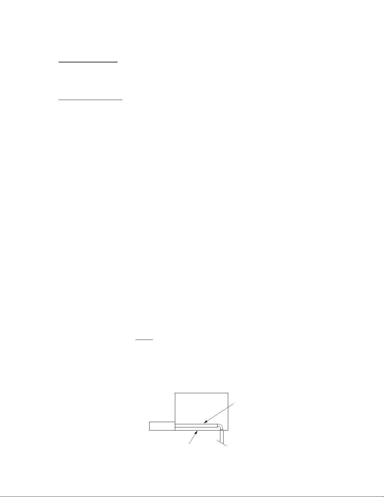
SINK DRAIN ASSEMBLY INSTRUCTIONS
1. Use tube, clamp and insulation provided to assemble drain.
2. To assure proper drainage, do not allow “trap” t o form in drain line. Be sure drain line runs flat with bottom
of the dispenser (See Figure 1).
3. Water pipe connections and fixtures connected directly to a potable water supply must be sized, installed
and maintained according to federal, state, and local laws.
4. The unit is now ready for operation.
DRAIN LINE
DISPENSER BOTTOM
FIGURE 1. SINK DRAIN ASSEMBLY
3 91803
Page 7

CLEANING INSTRUCTIONS
WARNING: DISCONNECT POWER BEFORE CLEANING! Do not use metal scrapers, sharp
objects or abrasives on the ice storage hopper, top co ver and t h e agitator disk; Damage
may result. Do not use solvents or other cleaning agents; they may attack the plastic
material.
DISPENSER
1. Clean the ice storage hopper at least once a month.
2. Lift off the agitator and the agitator disk. Wash with a mild detergent solution and rinse them thoroughly to
remove all traces of detergent.
3. Wash down the inside of the ho pper and top cover with a mild detergent solut ion and rinse thoroughly to
remove all traces of detergent.
4. Replace t he agitator.
5. Sanitize the inside of the hopper and agitator with a solution of 1/2 ounce of household bleach in 1 gallon of
water. (200 PPM)
6. Replace t he agitator disk. Sanitize as described in Step 5.
7. Remove i ce chute cover as follows:
A. Flex sides out ward to disengage lower pins.
B. Lift ice chute cover to disengage upper pins.
C. Lower ice chut e cover down out of unit. NOTE: it may be helpful to twist cover slightly.
8. With brush provided, clean the inside of the ice chute with a mild detergent solution a nd rinse thoroughly to
remove all traces of detergent.
9. Reverse steps above to reassemble ice chute.
10. Sanitize as described in Step 5.
COLD PLATE
1. Carefully remove the lower front panel of the ice dispenser.
2. Remove cold plate cover by lifting slightly in front and slide forward.
3. Wash down the inside of the cold plate, tray and cover with a mild detergent solution and rinse. A small,
long-handled brush will be found helpful in reaching the corners.
4. Slide the cover back, taking care that it is properly positioned on the cold plate.
5. Replace t he lower front panel, carefully feeding the tube and wires into the cabinet. Be sure not to punch
any tubing or wires between the panel and cabinet.
91803 4
Page 8

BEVERAGE SYSTEM
1. Remove faucet spouts, wash in mild detergent, rinse and replace.
2. Disconnect electrical power to the carbonato r. Shut off the water supply and close the CO2regulator to the
carbonator.
3. Disconnect the syrup tanks from the system.
4. Energize the beverage faucets to purge the remaining soda in the system.
5. Use a clean 5 gallon tank for each of the following:
A. Cleaning Tank - Fill with hot (120° - 140°) potable water.
B. Sanitation Tank - Fill with a chlorine sanitizing solution in the strength of 1/2 ounce of household
bleach (sodium hypochlorite) to 1 gallon of cold (ambient) potable water (200 PPM).
6. Repeat the following procedure on each of the units’ syrup product lines:
A. Connect the cleaning tank to the syrup line to be sanitized and to the CO2system.
B. Energize the beverage faucet until the liquid dispensed is free of any syrup.
C. Disconnect the cleaning tank and hookup the sanitizing tank to the syrup line and CO2system.
D. Energize the beverage faucet until the chlorine sanitizing solution is dispensed thro ugh the faucet.
Flush at least 2 cups of liquid to ensure that the sanitizing solution has filled the entire length of the
syrup lines.
E. Disconnect the sanitizing tank. Hookup the pro duct tank to the syrup line and to the CO2system.
F. Energ ize the faucet to flush the sanitizing solution from the syrup line and faucet. Continue to draw on
the faucet until only syrup is dispensed.
7. Repeat Step 2 in reverse order to turn on the carbonator. Dispense at least 1 cup of beverage from each
faucet. Check taste. Continue to flush if needed, to obtain a satisfactory tasting d rink.
5 91803
Page 9

MAINTENANCE
The following dispenser maintenance should be performed at the intervals indicated:
DAILY or as required
Remove foreign material from the vending area sink to prevent drain blockage.
WEEKLY or as required
Clean vending area. Check for prope r water drainage from the vending area sink.
MONTHLY
Clean and sanitize the hopper interior (see CLEANING INSTRUCTIONS).
OPERATING INSTRUCTIONS
Ice Dispensing: Depressing the operating lever activates a microswitch behind the front panel which ener-
gizes the a gitator motor and gate solenoid. This causes the agitator to rotate and the gate slide to lift, allowing
the ice to push out the gate opening.
Ice Level: (Standard Models): Remove the lid and fill the hop per with ice. Replace lid to avoid contamination
of ice.
For units equipped with the optional ice level light, low ice level in the storage hopper will be indicated when the
light is “on”.
CAUTION: Use caution to avoid spilling ice when filling d ispen ser. Immediately clean up
any spilled ice from filling or operating the unit. To prevent contamination of ice, the lid
must be installed on the unit at all times.
Automatic Ice Filling (“K” Models): The automa tic agitation time r maintains the ice at an even level which al-
lows the e ntire storage bin to fill before the ice machine shuts off. The ice maker control capillary bulb maintains
the ice level in the storage hopper. Consult the ice maker manual for location and operation of the ice maker
control.
Beverage System: Beverages may be dispensed by operating the lever on the appropriate faucets. On units
with cold plates (“C” models), periodic movement of the ice in the hopper is necessary to maintain the level of
ice on the cold plate. On initial start-up or after long, idle periods with no use, dispense several large cups of ice
(approximately 20-30 seconds total dispensing time) to allow ice to fill the cold plate cabinet. For manual-fill
units, add ice to the hopper as necessary to refill and then replace the lid. Allow 10-15 minutes for the cold plate
to cool down. Repeat this procedure whenever the dispenser has bee n standing overnight or other long periods
without ice use to prevent warm beverages on initial use. Start up the beverage system and adjust the faucets
to the proper brix. Contact your local syrup distributor for complete information on the beverage system.
GATE RESTRICTOR PLATE
CAUTION: Disconnect power to dispenser before installing, removing o r adjusting
restrictor.
91803
6
Page 10

INSTALL PLATE ON
STUDS AS SHOWN
FIGURE 2. GATE RESTRICTOR PLATE
ADJUSTMENT
This dispenser is provided with a gate re strictor plate, installed in its highest position.
This plate adjusts the rate of ice flow from the dispenser. In applications using buckets, carafes or other large
containers, the plate may be removed entirely for maximum ice flow. For glasses and cups, the plate may be
adjusted downward to reduce the flow of ice. The best position depends on the type of ice being used and the
size container and must be found by trial and error. Adjustment is made by loosening the upp er two ice chute
retaining nuts, sliding the restrictor plate to the desired position and re-tightening the nuts.
If the dispenser fails to dispense the ice when operated, check that the hopper has ice in it and that power is
being supplied to the unit. If the problem persists, check the following:
1. Determine if the agitator is rotating (check for the sound of ice movement in the hopper).
2. Observe whether t he gate is operating.
7 91803
Page 11

TROUBLESHOOTING GUIDE
Should your unit fail to operate properly, check that there is power to the unit and that the hopper contains ice.
If the unit does not dispense, check the following chart under the appropriate symptoms to aid in locating
the defect.
Trouble Probable Cause
BLOWN FUSE OR CIRCUIT BREAKER. A. Short circuit in wiring.
B. Defective ga te solenoid.
C. Defective agitator motor.
GATE DOES NOT OPEN. AGITATOR DOES
NOT TURN.
GATE DOES NOT OPEN OR IS SLUGGISH.
AGITATOR TURNS.
GATE OPENS. AGITATOR DOES NOT TURN. A. Agitator motor protector tripped.
A. No power.
B. Bent depressor plate (does not actuate switch).
C. Defective dispensing switch.
A. Defective ga te solenoid.
B. Weak gat e spring.
B. Defective ag itator motor.
C. Defective agitator relay.
ICE DISPENSES CONTINUOUSLY. A. Stuck or bent depressor plate (does not release
switch).
B. Defective di spensing switch.
C. Improper switch installation.
SLUSHY ICE. WATER IN HOPPER. A. Blocked drain.
B. Unit not level.
C. Poor ice quality due to water quality or ice maker
problems
ICE SOLIDIFIED IN HOPPER OR ICE AT
REAR CORNER ONLY.
NO ICE IN HOPPER. A. Ice maker malfunction.
ICE PACKED IN HOPPER. A. Defective or i mproperly adjusted ice maker control
BEVERAGES DO NOT DISPENSE. A. No 24 volt power to faucets.
BEVERAGES TOO SWEET. A. Carbonator not working.
A. Defective or i mproperly adjusted ice maker
thermostat.
(not shutting off).
B. No CO2pressure.
B. No CO2pressure in carbonator.
C. Faucet brix requires adjusting.
BEVERAGES NOT SWEET ENOUGH. A. Empty syrup tank.
B. Faucet brix requires adjusting.
BEVERAGES NOT COLD (UNITS WITH
BUILT-IN COLD PLATE).
Contact your l ocal syrup or beverage equipment distributor for additional information and troubleshooting of your
beverage system.
A. Unit standing with no ice in hopper, no ice in cold plate
cabinet.
891803
Page 12

POSITION ICE MAKER ON DISPENSER
TO COVER OPENING INTO STORAGE
HOPPER.
APPLY RTV AROUND INSIDE
OF ICE MAKER OUTLINE ON
DISPENSER COVER TO FORM
A SEAL.
REMOVE SCREWS AND
TURN BRACKET AROUND
180°, REPLACE SCREWS.
FIGURE 3. T J150-K ICE CUBER INSTALLATION
9
91803
Page 13

2 1/8 DIA.
(POWER CORD
AND DRAIN) OPENING REQUIRED FOR
BEVERAGE TUBING
30
2 5/16
2 9/16
1
4 1/2
14
1 1/8
8
18 1/2
1/2 DIA. (4)
27 3/4
30
FIGURE 4. MOUNTING TEMPLATE TJ150-B, BC
1091803
1 1/8
Page 14

15 1/4
17 5/8
27 5/8
30
8 5/8
34 15/32
32 7/8
11 11/32
FIGURE 5. SPECIFICATION DRAWING TJ150-B, BC
11
30
91803
Page 15

WATER
TANK
2
CO
REGULATORS
TANKS
SYRUP
15-50 PSIG
NOTE: REFERENCE ONLY
NOT FOR CONSTRUCTION
OPTIONAL: PRESSURE
60-100 PSIG
SUPPLY
REGULATOR
FILTER
CARBONATOR
5-15 PSIG
OR ROOT BEER
OPTIONAL-FOR DIET
S1 S2 S3 S4 S5 S6 S7 S8
ICE BANK
COLD PLATE OR
FIGURE 6. BEVERAGE SYSTEM SCHEMATIC “-B”MODELS
CW
1
FAUCETS
2
3
4
5
6
7
8
CW
91803
12
REMCOR “B”ICE/BEVERAGE DISPENSER
ITEMS OUTSIDE OF BROKEN LINES NOT
INCLUDED WITH UNIT. FAUCETS 5
THROUGH 8 ARE OPTIONAL.
Page 16

WATER
TANK
2
CO
REGULATORS
TANKS
SYRUP
OPTIONAL: PRESSURE
60-100 PSIG
15-50 PSIG
SUPPLY
REGULATOR
FILTER
CARBONATOR
5-15 PSIG
OR ROOT BEER
OPTIONAL-FOR DIET
1
FAUCETS
2
S1 S2 S3 S4 S5 S6 S7 S8
COLD PLATE
CW
3
4
5
6
7
8
CW
FIGURE 7. BEVERAGE SYSTEM SCHEMATIC “-BC”MODELS
NOTE: REFERENCE ONLY
NOT FOR CONSTRUCTION
REMCOR “BC”ICE/BEVERAGE
DISPENSER ITEMS OUTSIDE OF BROKEN
LINES NOT INCLUDED WITH UNIT.
FAUCETS 5 THROUGH 8 ARE OPTIONAL.
13
91803
Page 17

T’STAT LIGHT
WHT
ICE LEVEL
SIGNAL OPTION
BLK
MOTOR
HEATER
GROUND
NL
GRN
WHT
GATE
SOLENOID
1 1/4 AMP TIME
DELAY FUSE
KEY
SWITCH
OPTION
PORTION
CONTROL
OPTION
TO
TERMINAL
BOARD
WHT
24 V.
TRANSFORMER
BEVERAGE SYSTEM
WHT
RED
BLK
BLK
BEVERAGE
FAUCET
(TYPICAL)
PORTION
TIMER
SW
TD
OR
RED
DISPENSE
SWITCH
BLK
TERMINAL
BOARD
BLK
WHT
RED
RED
DISPENSE
SWITCH
AGITATION TIMER
WHT
C
NO
NC
PINK
RED
AGITATOR
MOTOR
CAPACITOR
SERVICE INFORMATION
DANGER!
7
8
FIGURE 8. W IRING DIAGRAM TJ150-BC DISPENSER
ELECTRIC SHOCK HAZARD.DISCONNECT POWER
BEFORE SERVICINGUNIT.
SOLENOID
ADJUSTMENT
WHEN REPLACING SOLENOID
ADJUST TO 7/8 INCH AS SHOWN
BEFORE TIGHTENING
MOUNTING SCREWS
1491803
Page 18

12
4
17
20
14
10
16
1
15
2
8
24
19
9
11
23
22
5
13
3
6 7
18
FIGURE 9. F INAL ASSEMBLY
15 91803
Page 19

FINAL ASSEMBLY PARTS LIST
1
2
1
3
Item No. Part No. Description
1 21491 Gate Slide
2 23062 Foam Shield
3 21515 Depressor Lever
4 24069 Agitator
5 30895 Dispense Switch
6 31007 Switch Boot
7 31163 Switch Insert
8 31091 Transformer
9 31889 Agitator Motor
10 50454 Motor Shaft Seal
11 50806 Motor Gasket
12
13
14 53015 Ice Chute Back Section
15 53016 Ice Chute Cover
16 50770 Gate Gasket
17 70570 Sink Grill
18 70439 Leg (“B”, “BC” Models Only)
19 30774 Capacitor
20 31093 Solenoid Assembly (See Page 17)
21 70438 Rebuilding Kit
22 22644 Depressor Retainer
23 30794 Agitation Motor Heater (“B”, “KBC” Models Only)
24 31763 Agitation Timer (“BC”, “KBC” Models Only)
51432 Lid (“B”, “BC”)
24200 (“KB”, “KBC”)
51430 Sink (“B” Models Only)
51431 (“BC” Models Only)
1691803
Page 20

22
17
19
22
4
1
4
18
21
16
15
14
19
13
9
2
3
5
22
20
6
8
11
10
12
7
FIGURE 10. SOLENOID ASSEMBLY -- EXPLODED VIEW AND PARTS LIST
Index
No.
1 21493 1 Solenoid Mounting Plate
2# 31551 1 Solenoid Service Kit
3 70171 2 8--32 x 3/8 Phil Tr HD Screw
4 70121 2 No. 8 Lockwasher
5 50752 3 Isolator
6* 50789 2 Bumper Assembly
7* 70423 1 Cotter Pin
8* 10080 1 Gate Lift Rod
9 10081 1 Gate Lift Rod Bushing
10 50754 1 Gate Arm Bearing
11 21492 1 Gate Lift Arm
12 70043 1 Flatwasher
13* 70422 1 Spring
14 70263 1 1/4-20 x 3/4 Hex Hd Screw
15 70048 1 1/4 Lockwasher
16 70066 1 1/4 Flatwasher
17 10077 1 Pivot Bearing
18 30227 1 1/4 Quick Connect Tab
19 50305 ---- Lubricant
20* 21592 1 Solenoid Linkage Pin
21* 70433 2 Retainer Ring
22 51088 ---- Loctite
----* 70438 ---- Rebuilding Kit
Part No. Qty . Name
NOTE: * Parts supp lied with rebuild ing kit.
# 31551 solenoid supplied with items 20 & 21.
17 91803
Page 21

IMI CORNELIUS INC.
ONE CORNELIUS PLACE
ANOKA, MN. 55303--6234
TELEPHONE (800) 238--3600
FACSIMILE (612) 422--3232
TECH SVC 1-800-535-4240
WARRANTY
IMI Cornelius Inc. and Remcor Products Company warrants that all equipment and parts are free from
defects in material and workmanship under normal use and service. For a copy of the warranty applicable
to your Cornelius and or Remcor product, in your country, please write, fax or telephone the
IMI Cornelius office nearest you. Please provide the equipment model number, serial number and the
date of purchase.
IMI Cornelius Offices
AUSTRALIA D P.O. 210, D RIVERWOOD, D NSW 2210, AUSTRALIA D (61) 2 533 3122 D FAX (61) 2 534 2166
AUSTRIA D AM LANGEN FELDE 32 D A-1222 D VIENNA, AUSTRIA D (43) 1 233 520 D FAX (43) 1-2335-2930
BELGIUM D BOSKAPELLEI 122 D B-2930 BRAASCHAAT , BELGIUM D (32) 3 664 0552 D FAX (32) 3 665 2307
BRAZIL D RUA ITAOCARA 97 D TOMAS COELHO D RIO DE JANEIRO, BRAZIL D (55) 21 591 7150 D FAX (55) 21 593 1829
ENGLAND D TYTHING ROAD ALCESTER D WARWICKSHIRE, B49 6 EU, ENGLAND D (44) 789 763 101 D FAX (44) 789 763 644
FRANCE D 71 ROUTE DE ST. DENIS D F-95170 DEUIL LA BARRE D PARIS, FRANCE D (33) 1 34 28 6200 D FAX (33) 1 34 28 6201
GERMANY D CARL LEVERKUS STRASSE 15 D D-4018 LANGENFELD, GERMANY D (49) 2173 7930 D FAX (49) 2173 77 438
GREECE D 488 MESSOGION AVENUE D AGIA PARASKEVI D 153 42 D ATHENS, GREECE D (30) 1 600 1073 D FAX (30) 1 601 2491
HONG KONG D 1104 TAIKOTSUI CENTRE D 11-15 KOK CHEUNG ST D TAIKOKTSUE, HONG KONG D (852) 789 9882 D FAX (852) 391 6222
ITALY D VIA PELLIZZARI 11 D 1-20059 D VIMARCATE, ITALY D (39) 39 608 0817 D FAX (39) 39 608 0814
NEW ZEALAND D 20 LANSFORD CRES. D P.O. BOX 19-044 AVONDALE D AUCKLAND 7, NEW ZEALAND D (64) 9 8200 357 D FAX (64) 9 8200 361
SINGAPORE D 16 TUAS STREET D SINGAPORE 2263 D (65) 862 5542 D FAX (65) 862 5604
SPAIN D POLIGONO INDUSTRAIL D RIERA DEL FONOLLAR D E-08830 SANT BOI DE LLOBREGAT D BARCELONA, SPAIN D (34) 3 640 2839 D FAX (34) 3 654 3379
USA D ONE CORNELIUS PLACE D ANOKA, MINNESOTA D (612) 421-6120 D FAX (612) 422-3255
SD 99-3
1/16/96
18
91803
Page 22

CORPORATE HEADQ UARTERS:
Glendale Heights, IL 60139
Remcor Incorporated
500 Regency Drive
708. 980.6900
 Loading...