

Page 1

SPIRAL ICE ICEMAKER--DISPENSER
MODEL NUMBER:SID350A/35S
Operator’s Manual
Distributed By:
Commercial Refrigeration Service, Inc.
WWW.CorneliusParts.COM
WWW.ICeCubes.NET
(866) 423-6253
(623) 869-8881
SID350W/35S,
SID350A/35S-B
SID350W/35S-B
Part No. 91626
Revised June, 1997
Revision
THIS DOCUMENT CONTAINS IMPORTANT INFORMA
This Manual must be read and understood before installing or operating this equipment
REMCOR INC: 8/95
B
TION
PRINTED IN U.S.A
Page 2

TABLE OF CONTENTS
SAFETY PRECAUTIONS 1...................................................
DESCRIPTION 2............................................................
UNPACKING 2..........................................................
INSTALLATION 3............................................................
LOCATION 3............................................................
PLUMBING 3...........................................................
ELECTRICAL 3.........................................................
BEVERAGE SYSTEM 7..................................................
INSTALLATION 7......................................................
START UP 7............................................................
OPERATING INSTRUCTIONS 9...............................................
MAINTENANCE 13...........................................................
CLEANING INSTRUCTIONS 13...........................................
ICEMAKER SECTION 13.................................................
DISPENSER SECTION 14...............................................
BEVERAGE SYSTEM 14..................................................
MAINTENANCE AND ADJUSTMENTS 16.......................................
Page
THERMOSTAT ALTITUDE ADJUSTMENT 16................................
BIN STAT 16............................................................
ICE PRODUCTION ADJUSTMENT 16......................................
CLEARING EVAPORATOR FREEZE-UP 16.................................
SERVICE PROCEDURES 17..............................................
HIGH PRESSURE CONTROL 17..........................................
BIN THERMOSTAT 17...................................................
CONDENSER (AIR COOLED) 18.........................................
TROUBLESHOOTING GUIDE 23...............................................
WARRANTY 37..............................................................
LIST OF FIGURES
FIGURE 1. SID 350 / 35S 4...............................................
FIGURE 2. SID 350 / 35S-B 5.............................................
FIGURE 3. MOUNTING TEMPLATE SID 350A/35, SID 350W/35,
SID 350A/35S-B, SID 350W / 35S-B 6......................................
FIGURE 4. BEVERAGE SYSTEM SCHEMATIC “-B”MODELS 8..............
FIGURE 5. SID 350/35 115/1/ 60 HZ SCHEMATIC 10.........................
FIGURE 6. SID 350/35 115/1/60 HZ WIRING 1 1.............................
FIGURE 7. REFRIGERATION SCHEMATIC 12...............................
FIGURE 8. SERVICE PAR TS LIST CONDENSING UNIT 34...................
FIGURE 9. CABINET ASSEMBLY EXPLODED VIEW AND SERVICE PARTS 35.
FIGURE 10. SOLENOID ASSEMBLY - EXPLODED VIEW & PARTS LIST 36.....
i
91626
Page 3

TABLE OF CONTENTS (cont’d)
LIST OF TABLES
Page
TABLE 1. SPECIFICATIONS 2............................................
TABLE 2. ICEMAKER CAPACITIES (LBS./DAY) 2...........................
TABLE 3. CONTROLLER 9...............................................
Manufactured Under One or More of the Following Patent Numbers:
3,211,336, 3,274,792, 3,393,839 , 3,517,860, 3,739,842, 4,215,803, 4,227,377, 4,300,3594,346,824
Canadian Patent Numbers912,514 (10/72), 936,855 (11,73), 4,429,543, 4,921,149
Other Patents Pending
91626
Page 4

SAFETY PRECAUTIONS
Always disconnect power to the dispenser before servicing or cleaning.
Never
occurs automatically when the dispenser is energized!
This ice dispenser has been specifically designed to provide protection against personal injury and eliminates
contamination of ice. To insure continued protection and sanitation, observe the following
IMPORTANT INSTALLATION NOTICE
An Everpure Model 9320-42, System IV Model DB900, or equal, icemaker quality water treatment unit MUST
BE INSTALLED in the water supply line to the icemaker. Failure to do so may result in poor quality ice, low production output and may cause premature failure of icemaker evaporator and void the extended evaporator warranty.
This icemaker is provided with a stainless steel evaporator, designed to last the life of the product. However,
some of the chemicals in treated and untreated water, specifically chlorine and sulfur (sulfide), have the ability to
attack stainless steel and cause premature failure. An initial investment in proper water treatment will pay for
itself in increased production, quality and long life of the product.
place hands inside of hopper or gate area without disconnecting power to the dispenser. Agitator rotation
ALWAYS be sure the removable lid is properly installed to prevent unauthorized access to the hopper interior and possible contamination of ice.
ALWAYS be sure the upper and lower front panels are securely fastened.
ALWAYS keep area around the dispenser clean of ice cubes.
1 91626
Page 5
DESCRIPTION
The REMCOR S.I.D. (Spiral Icemaker Dispenser) is a unique, self-contained, counter-top style unit which automatically makes hard, clear cube-quality ice and stores it in a sealed hopper for sanitary dispensing. The ice is
made by a new, patented process on a spiral shaped stainless steel evaporator and produces tube cube quality
ice on the outside of the tubes. There are no augers, no compressing of flaked ice, no bearings and no high
gear motor loads in the icemaking process. The unit has been designed to be simple, yet effective, to provide
many years of trouble free operation.
Table 1. Specifications
Compressor: HP 1/2
Refrigerant: R-22 1 lb.
Pressure Controls Setting: High: 400 Psig Low: 10 Psig
Voltage: 115 / 1 / 60
Amps: 16 Amps
Circuit Ampacity: 20 Amps
Fuse Size: 20 Amps
Ice Storage Capacity: 35 lbs.
Ice Making Capacity: Up to 350 lbs./24 hours
Shipping Weight: 170 lbs.
Ice Making Capacity Per 24 hr / lb at Given Conditions
Table 2. Icemaker Capacities (lbs./day)
Water Temperature °F
AIR TEMP. ° F 40 50 60 70 80
60 391 372 355 342 318
70 356 334 321 310 301
80 316 303 295 281 270
90 290 267 259 241 241
UNPACKING
1. With the unit upright carefully remove the shipping carton. Inspect for shipping damage and report any
such damage to the shipper immediately.
2. Unscrew and remove the top cover of the unit.
3. Remove shipping tape from storage hopper and agitator in storage hopper .
291626
Page 6
INSTALLATION
LOCATION
Locate the icemaker dispenser indoors in a well ventilated area. Avoid exposure to direct sunlight and/or heat
caused by radiation. Ambient room temperature must be in the range of 60° to 90° F. Do not install unit in an
enclosed area where heat build-up could be a problem. Note: Air flow direction and spacing required to Figure 1.
Consult Figure 1A and 1B for utility connection locations.
Consult Figure 2 for dimensions for mounting unit to the counter with the hardware provided. Note that the unit
must be level for proper operation.
The unit must be sealed
cut in the counter. Locate the desired position for the unit then mark the outline dimensions and cut-out locations using the template drawing cut openings in counter.
Apply a continuous bead of NSF listed silastic sealant (DOW 732 or equal) approximately 1/4”inside of the unit
outline dimensions, and around all openings. Then position the eater of the counter within the outline dimensions. All excess sealant must be wiped away immediately.
to the counter. The template drawing (Figure 2) indicates the openings which must be
PLUMBING
Connect the icemaker to a cold, potable water source, suitable for drinking. This water source must comply with
the basic plumbing code of the Building Officials and Code Administrators International Inc. (BOCA) and the
Food Service Sanitation Manual of the Food and Drug Administration. Do not install unit on a water softener
line. It is recommended that a hand shut-off valve and strainer be used on the incoming supply line. (See Figure
2 for size and location.) For proper operation of the incoming water supply pressure must be in the range of
30-90 PSIG. Install a pressure regulating valve if above this range!
IMPORTANT: To insure proper icemaker operation and also to reduce the frequency of water-related
service problems, a water filter should be installed. REMCOR recommends the use of one of the
following basic systems.
1. Everpure inc.
660 N. Blackhawk drive
Westmont, IL 60559
(708) 654-4000
2. System IV
16632 Burke Lane
Huntington Beach, CA 92647
Insurice Twin System
For specific recommendations on these filter systems for your local water conditions, consult with a distributor in
your area or contact the filter manufacturer.
Connect separate drain lines to all drain connections. See Figure 2 for size and location. These lines must pitch
downward to and open drain and must contain no traps, or improper drainage will result. Separate, not joined
drain lines are required to prevent back flow.
NOTE: In areas where consistently warm water temperatures are encountered, the use of a pre-cooler
in the water line is recommended to maximize the ice production of this unit.
#9320-42
ELECTRICAL
Thisunitissuppliedwitha2wire-withground 6 foot long conductor and suitable plug for a standard 115 volt 20
amp circuit receptacle. This cord exits the unit through the base and should be routed per the National Electric
Code.
WARNING: Only qualified personnel should service internal components or electrical
wiring.
Basic Water System
3
#B1000
91626
Page 7
AIR
FLO
W
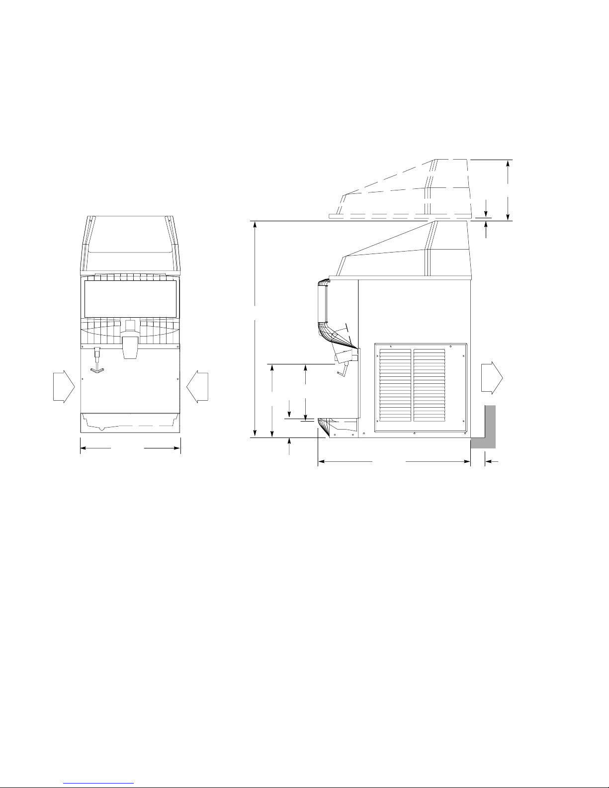
18.188
AIR
FLO
W
39.625
13.500
3.500
10.625
27.875
11.500
.500
AIR
FLO
W
3-MIN
1. Minimum 3”clearance must be provided at the rear of unit. (air flow out)
2. Inlet air flow may only be restricted on one side. (at least one side must be
open for proper performance)
3. Minimum top clearance must be 11.500.
FIGURE 1. SID 350 / 35S
491626
Page 8
AIR
FLO
W
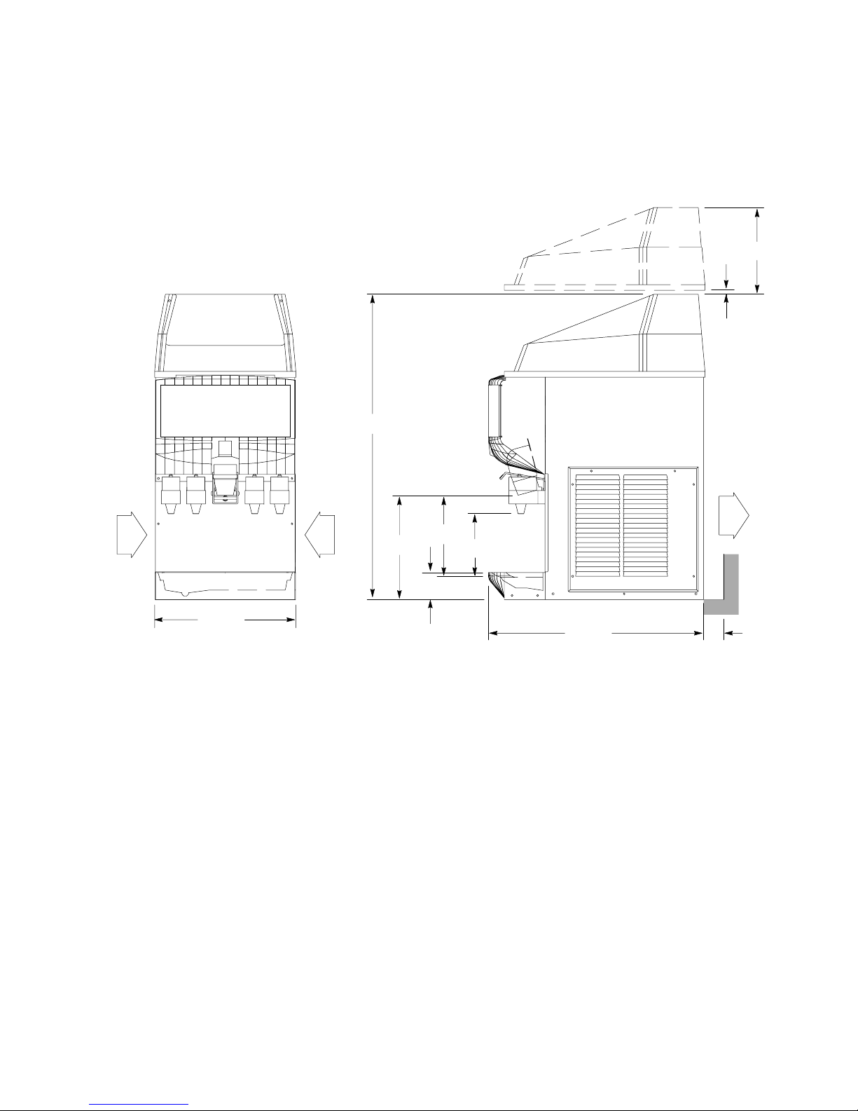
18.188
AIR
FLO
W
39.625
13.500
10.625
3.500
8.250
27.875
11.500
.500
AIR
FLO
W
3-MIN
1. Minimum 3”clearance must be provided at the rear of unit. (air flow out)
2. Inlet air flow may only be restricted on one side. (at least one side must be
open for proper performance)
3. Minimum top clearance must be 11.500.
FIGURE 2. SID 350 / 35S-B
5 91626
Page 9
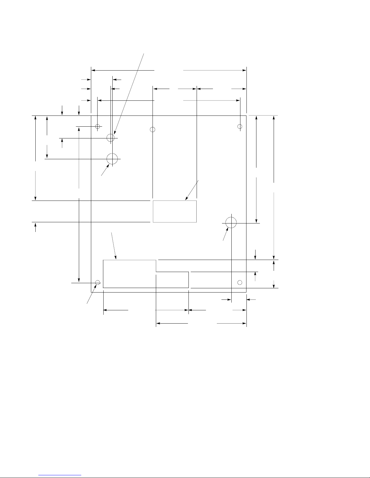
2 37/64
5
POWER CORD
1 5/8 MIN DIA.
CLEARANCE HOLE
17 29/32
27/16
21/4
5 53/4
3/4 16 13/32
1 17/64
9 27/32
18 1/32
21/2
3/8-16 THREADS (4) PLCS
FORLEGSORIFREQD.
1/2 DIA. HOLES IF
MOUNTED TO COUNTER
ICEMAKER WATER-IN
3/8 O.D. TUBE COMP
FITTING 1 1/4 DIA.
CLEARANCE HOLE
BEVERAGE TUBING CUTOUT
(FOR ”B”MODELS ONLY)
*SINK DRAIN AND
DRAIN COLLECTOR
OPENING
WATER COOLED CONDENSER
INLET 3/8 O.D. COMP. FITTING.
1 1/4-IN DIA. CLEARANCE HOLE
6 43/649 55/64
10 13/32
12 3/8
16 11/16
1 23/64
3 15/64
13/4
*NOTE:
DRAIN COLLECTOR REQUIRES
1-IN BARBBY MPT;
1-IN I.D. PLASTIC TUBING
FIGURE 3. MOUNTING TEMPLATE SID 350A/35, SID 350W/35, SID 350A/35S-B, SID 350W / 35S-B
691626
Page 10

BEVERAGE SYSTEM
“B”models contain beverage faucets only and must be supplied with cold product from any remote cold plate or
refrigerated soda factory.
Installation
1. Locate the required openings in the counter top for the beverage lines as shown in Figure 2.
2. Carefully pull the beverage tubes through the bottom opening in the unit and through the clearance opening
in the counter.
3. Connect the beverage system product lines as indicated in Figure 3. This work should be done by a qualified service person. Note that the hoses are marked with numbers 1 - 4 for syrup connections and “CW”for
carbonated water connection.
START UP
1. Remove front and side service panels and connect the water supply to the water valve.
2. Turn on water to icemaker. Depress fill switch to fill evaporator with water before starting unit.
3. Put the stop/rum switch in the “run”position. Observe that the icemaker goes through proper icemaking
and harvest cycle. If unit malfunctions, consult troubleshooting section.
NOTE: Do to meltage loss because of warm storage hopper, it will take longer to fill the hopper the
first time than when the icemaker has been operating continuously.
4. Depress the vend switch. Check that both the gate solenoid and agitator motor are energized simultaneously to lift the gas slid and rotate the agitator in the storage hopper, respectively. If either component
malfunctions, consult the troubleshooting section.
5. For beverage units, start up the beverage system and adjust the faucets to the proper brix. Contact your
local syrup distributor for complete information on the beverage system.
6. The bin thermostat is calibrated at an atmospheric pressure equivalent at 500 feet above sea level. For
locations at higher elevations, it may be necessary to re-adjust these controls. Consult the maintenance /
adjustment procedures section.
7 91626
Page 11
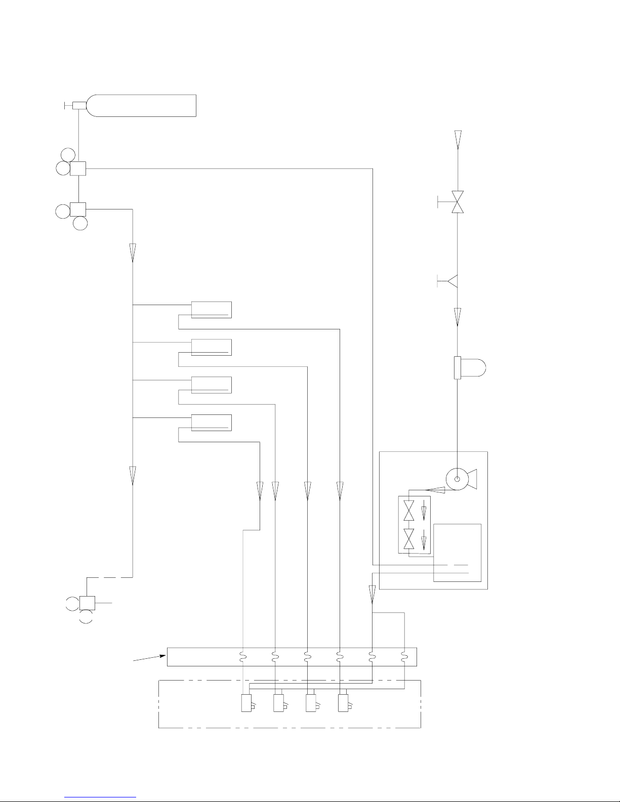
O
PTIONALFO
RDIET
R
EGULATORS
TANK
2
CO
WATER
SUPPLY
REGULATOR
FILTER
OPTIONAL PRESSURE
FIGURE 4. BEVERAGE SYSTEM SCHEMATIC “-B” MODELS
CARBONATOR
SYRUP TANKS
S1 S2 S3 S4
15-50 PSIG
60-100 PSIG
VALVE
DOUBLE CHECK
5-15 PSIG
OR ROOT BEER
COLD PLATE OR
REFRIGERATED ICE BANK
91626
1
2
3
4
CW
CW
INCLUDED WITH UNIT
ITEMS OUTSIDE OF BROKEN LINES NOT
REMCOR ”B”ICE/BEVERAGE DISPENSER
8
Page 12
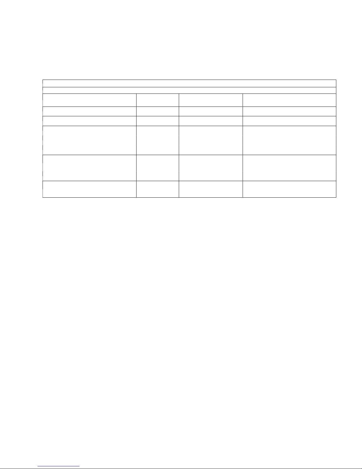
OPERATING INSTRUCTIONS
A temperature sensing control bulb, located in the storage hopper, starts and stop the icemaking process (compressor) in response to the ice level in the hopper. With this ice level control “calling”for ice (hopper ice level is
low), the total cycle timer is energized. This timer, in turn, energizes the harvest timer for its’respective “on”
times. The chart below details this sequence of events.
Table 3. CONTROLLER
TOTAL
TIME
Start - 35 seconds X 1. Hot gas solenoid valve open.
35 - 570 seconds
35 - 65 seconds X 1. Harvest motor one.
65 - 570 seconds (air-cooled)
65 - 510 seconds (water-cooled)
35 - 570 seconds (air-cooled)
35 - 510 seconds (water-cooled)
CYCLE TIME
X 1. Hot gas solenoid valve closed.
HARVEST TIME ACTION
2. Water fill valve on.
3. Agitator motor on.
X 1. Harvest motor and agitator
motors off.
2. Water fill valve off.
At the 35 second point in the cycle, the host gas solenoid valve closes and ice begins to form on the stainless
steel tubing coils of the evaporator. Ice will continue to form on these coils for the remainder of the cycle time.
At the end of the icemaking cycle, the total cycle timer (repeat starts sht harvest portion of the cycle again.
When ice contacts the control bulb in the storage hopper, the control switches the compressor off. This control
(thermostat) also switches off power to the total cycle timer. With power de-energized, the timer resets itself to
the “start”portion of the cycle. Therefore, the unit will always start with the hot gas/harvest portion of the ice
making cycle to ensure that the evaporator is cleared of any remaining ice.
991626
Page 13
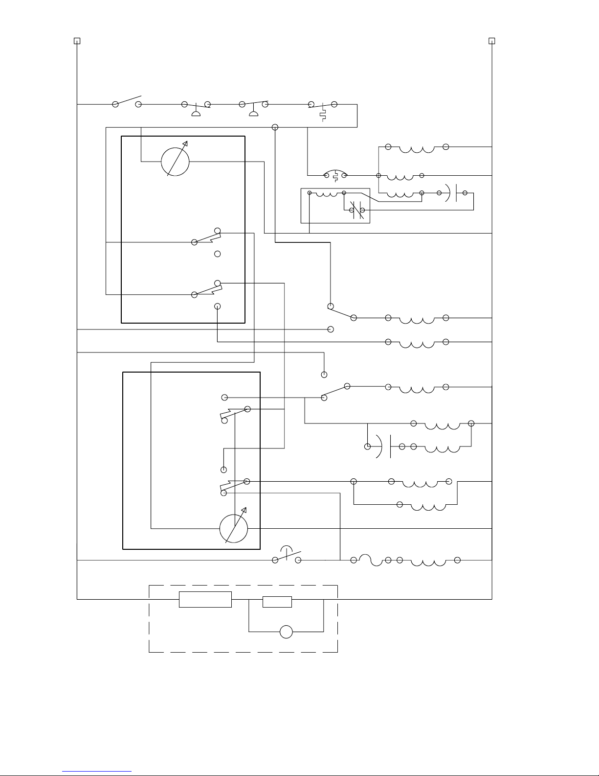
L
STOP/
RUN
8
HPS
TOTAL CYCLE
ADJUSTMENT
1
NC
LPS
BIN T’STAT
1
START
RELAY
2
CONDENSER FAN
(AIR--COOLED)
TP
COMPRESSOR
C
R
S
START CAP
N
REPEAT
CYCLE
TIMER
(RCT)
INTERVAL
TIMER
(IT)
C
C
HARVEST
ADJUSTMENT
NO
NC
NC
8
NO
NO
NO
NC
C
C
1
VEND SWITCH
RUN
CLEAN
NO
NC
FILL
SWITCH
C
CAP
WATER FILL VALVE
F
AIR PUMP
HG SOL VALVE
HARVEST MOTOR
RED
BLUE
AGITATORMOTOR
BLUE
RED
GATE SOLENOID
BALLAST
LIGHTED DISPLAY OPTION
FIGURE 5. SID 350/35 115/1/ 60 HZ SCHEMATIC
LAMP
STARTER
10 91626
Page 14

RED
RED
WHT
RED
BLUE
HARVESTMOTOR
ORG
1
BIN
3
T”STAT
2
RUN
STOP
CLEAN
RUN
NC NO
20A
6A
B
L
U
E
B
R
N
C
BLK
BLK
BLK
PINK
PUR
YEL
BLK
B
L
K
G
W
B
H
R
L
T
N
K
WHT
L2
L1
BLK
WHT
W
H
T
W
H
T
NEUTRAL/WHITE
RED
RED
W
W
W
H
H
H
T
T
T
WHT
W
H
T
ORG
CNONC
L2
L1
RED
P
U
R
NCNOC
R
E
D
CNONC
PUR
BLK
115 V
20 A
WHT
NCNOC
P
U
R
W
H
PUR
BLUE
YEL
T
P
U
R
R
E
D
W
H
T
W
H
T
YEL
PUR
ORG
BLK
YEL
BRN
WHT
RED
GRN
HIGH PRESSURE
SAFETY CONTROL
WHT
RED
BLUE
WHT
WHT
BLK
RED
C
VEND
SWITCH
YEL
WHT
WHT
RED
C2
3S
R
RED
RED
HG SOLVALVE
NC
NO
BLK
BLK
GRN
AIR PUMP
GATE
SOLENOID
RED
1
YEL
WHT
WA TERFILL
VALV E
BLUE
YEL
BLK
RED
LOW PRESSURE
SAFETY CONTROL
WHT
COMPRESSOR ELECTRICBOX
S
C
R
RED
COMPRESSOR
MOTOR
BLUE
BALLAST
AGITA TOR
MOTOR
LPS
START
RELAY
RED
LIGHTED DISPLAY
BLUE
BLUE
LAMP
STARTER
COND.FAN
CF
AIR COOLED
COMPRESSOR
STARTCAP.
MOTOR
FIGURE 6. SID 350/35 115/1/60 HZ WIRING
1191626
Page 15

LOW PRESSURE
SERVICE PORT
PRESSURE
CONTROL
COMPRESSOR
TXV BULB
LOW
HIGH SIDE
SERVICE
PORT
TXV PRESSURE
TAP
HIGH
PRESSURE
CONTROL
HOT GAS
SOLENOID
VALVE
AIR--COOLED MODELS
A
CONDENSER
CONDENSER
FAN
B
FILTER/DRIER
EVAPORATOR
EXPANSION
VALVE(TXV)
SUCTION
ACCUMULATOR
WATER- -COOLED MODELS
PRESSURE
REGULATING
VALVE
A
B
CITY
WATER
DRAIN
FIGURE 7. REFRIGERATION SCHEMATIC
12 91626
Page 16

MAINTENANCE
It is recommended that the air cooled condenser be cleaned every 3 months or sooner depending on the operating environment for proper refrigeration system performance, Check that this condenser is free of dirt/foreign
material that could cause air flow blockage.
cleaning of the icemaker is recommended on a regular basis not only for sanitary reasons but also to maintain
the performance of the unit. Build-up of lime and scale can hinder icemaking production rates and interfere with
proper dispensing of the ice. See the cleaning section for the recommended procedure.
Periodically, check the vending area sink for proper water drainage. Remove any foreign material from the sink
to prevent drain blockage.
CLEANING INSTRUCTIONS
IMPORTANT: The icemaker should be cleaned at a minimum of 3 month intervals or more frequently
depending on local water conditions. The storage hopper interior should be cleaned at
least once a
WARNING: Do no use metal scrapers, sharp objects or abrasives on the surface of the
storage hopper, as damage may result. Do not use solvents or other cleaning agents as
they may attack the plastic surface. Use only the recommended chemicals and solutions
for both the icemaker and hopper
month.
Icemaker Section
1. Remove top cover, lower front panel and right side access panel.
2. Put toe stop/run switch in the “stop”position at the end of the harvest cycle. An alternate method would be
to stop the unit during the icemaking cycle and allow ice in the evaporator to melt by waiting for at least 1
hour before beginning the cleaning procedure. The flush switch can be depressed to bring in warmer water
to help the melting process.
WARNING: Electrical power is on to unit during icemaker cleaning mode. To avoid
possible injury, do not reach into hopper or into icemaker nozzle. Do not contact exposed
electrical wiring and components.
3. Plug icemaker drain line located in the drain collector at condenser fan motor. (1-1/4 OD hose).
4. Fill icemaker drain hose with water by pushing fill switch.
5. Add 4 oz. of Virginia Ice Machine Cleaner (or equivalent) through the evaporator outlet.
WARNING: Virginia Ice Machine Cleaner (or equivalent is a mild acid. Normal care should
be taken - keep out of eyes and cuts.
operate unit in the cleaning mode without the ice drop cover in place. There may be some
overflow of cleaning solution through the evaporator vent tube during the cleaning cycle.
Read warnings on package before using. Do not
6. Seal the evaporator outlet with plastic lug provided with the unit.
7. Push fill switch and fill evaporator (when fluid flows out of evaporator through vent tube) let go of fill switch.
8. Put the clean/run switch in the “clean”position. Allow unit to run in the cleaning mode for at least 30 minutes.
1391626
Page 17

9. Open drain line. To avoid splash, drain the drain line to a separate container.
10. Push fill switch and hold for 6 minutes to flush solution out of evaporator. Drain line should be in the drain
collector.
11. Plug drain line.
12. Push fill switch and hold for 1 minute to flush solution out of vent line
13. Open drain line. Put clean/run switch in the “run”position. Remove plug from evaporator.
14. Put the stop/run switch in the “run”position and allow unit to run through at least 3 complete icemaking and
harvest cycles, and until ice is free of “sweet”taste.
CAUTION: If unit fails to harvest, put the stop/run switch in the “stop”position and flush
the evaporator with hot water to melt remaining ice and repeat steps 10, 11, 12 and 13 to
clean out remaining solution.
15. Dispense all ice out of storage hopper and discard.
Dispenser Section
1. turn off main electrical power supply to machine.
2. Remove agitator assembly from storage hoper and wash and rinse it thoroughly.
3. Wash down all inside surfaces of the ice storage area including the top cover with a mild
and rinse
4. Replace agitator.
5. Sanitize the inside of the hopper and agitator with a solution of 1 ounce of household bleach in 2 gallons of
water. (200 PPM)
6. Replace the agitator disk. Sanitize as described in Step 5.
7. Remove Ice Chute cover as follows:
A. Flex sides outward to disengage lower pins.
B. Lift Ice Chute cover to disengage upper pins.
C. Lower Ice Chute cover down out of unit. Note: it may be helpful to twist cover slightly.
8. With brush provided clean the inside of the ice chute with a mild detergent solution and rinse thoroughly to
remove all traces of detergent.
9. Reverse steps above to reassemble ice chute.
10. Sanitize as described in Step 5.
thoroughly to remove all traces of detergent.
detergent solution
11. Turn on the electrical power supply. The icemaker is ready for normal operation.
BEVERAGE SYSTEM
1. Remove faucet spouts, wash in mild detergent, rinse and replace.
2. Disconnect electrical power to the carbonator. Shut off the water supply and close the CO
carbonator.
regulator to the
2
14 91626
Page 18

3. Disconnect the syrup tanks from the system.
4. Energize the beverage faucets to purge the remaining soda in the system.
5. Use a clean 5 gallon tank for each of the following.
A. Cleaning tank
B. Sanitation Tank
- fill with hot (120° - 140°) potable water.
- Fill with a chlorine sanitizing solution in the strength of 1/2 ounce of household
bleach (sodium hypochlorite) to 1 gallon of cold (ambient) potable water (200 PPM).
6. Repeat the following procedure on each of the units’syrup product lines:
A. Connect the cleaning tank to the syrup line to be sanitized and to the CO
system.
2
B. Energize the beverage faucet until the liquid dispensed is free of any syrup.
C. Disconnect the cleaning tank and hook-up the sanitizing tank to the syrup line and CO
system.
2
D. Energize the beverage faucet until the chlorine sanitizing solution is dispensed through the faucet.
Flush at least 2 cups of liquid to insure that the sanitizing solution has filled the entire length of the
syrup lines. Allow sanitizing solution to remain in product line for 15 minutes before processing.
E. Disconnect the sanitizing tank. Hook-up the product tank to the syrup line and to the CO
system.
2
F. Energize the faucet to flush the sanitizing solution from the syrup line and faucet. Continue to draw on
the faucet until only syrup is dispensed.
7. Repeat Step 2 in reverse order to turn on the carbonator. Dispense at lease 1 cup of beverage from each
faucet. Check taste. Continue to flush if needed, to obtain a satisfactory tasting drink.
1591626
Page 19

MAINTENANCE AND ADJUSTMENTS
THERMOSTAT ALTITUDE ADJUSTMENT
Bin Stat
IMPORTANT: Adjust the bin t’stat setting only if storage hopper overfill is a problem.
1. Remove the top plastic cover .
2. The adjustment screw is located at the right upper rear corner of the unit behind the hopper-evaporator
partition.
3. For altitudes up to 6000 ft., turn the adjustment screw COUNTERCLOCKWISE as follows:
ELEVATION (FT.) CCW TURN
2000 1/13
4000 1/6
6000 1/4
4. For altitudes above 6000 ft., consult the factory.
ICE PRODUCTION ADJUSTMENT
1. Remove the top cover and lower front panel.
2. Collect and weigh the ice produced during the harvest cycle. The amount of ice harvested should be 1.9 to
2.1 pounds.
A. Put the stop/run switch in the “stop”position. (if the unit is in the icemaking cycle, stop the unit at the
end of the harvest cycle.
3. If ice weight is not in the 1.9 to 2.1 pound range, make adjustments by adding or subtracting time to the
total cycle time. More time = more ice.
4. Return unit to normal icemaking mode and repeat steps 2 and 3 until proper amount of ice delivered per
cycle.
CLEARING EVAPORATOR FREEZE-UP
WARNING: To prevent possible injury, do not stick fingers or hand into icemaker nozzle or
hopper with power applied to unit.
1. Remove four (4) screws and remove the hopper cover.
2. Put the stop/run switch in the “stop”position.
3. Close the water supply valve to the icemaker.
4. Drain evaporator by disconnecting the water inlet tube at the bottom of the evaporator, when empty reconnect water inlet.
1691626
Page 20

5. Pour hot water into the evaporator ice exit opening. it will be necessary to use either a funnel or a container
with a spout. Fill the evaporator completely.
6. Drain the evaporator. Repeat steps 5 and 6 as required to insure that all of the ice in the evaporator is
melted.
7. Open the water supply valve and refill evaporator.
8. Consult the toubleshooting guide to determine cause of freeze-up before putting unit back in service.
SERVICE PROCEDURES
High Pressure Control
The high pressure control is factory set at 400 PSIG. To check the setting, install a refrigeration discharge pressure gauge on the service port located on the compressor discharge line. Remove the front and right side panels to access this port and high pressure control. Disconnect the electrical power to the condenser fan motor
leads in the control box. Run the icemaker to determine the control cut-out point. Adjust if necessary . this control is manual reset type; the reset lever is located behind the low pressure control next to the electric box on
top of the high pressure control. Push in to reset. If the icemaker will not run after the control has been reset
(with the refrigerant pressure less than 350 PSIG), replace the control. The adjustment screw is located on the
top of the control.
Bin Thermostat
1. The bin thermostat is located in the upper right rear corner of the unit under the cabinet flange.
2. To adjust the thermostat, remove the top plastic cover from the unit. The adjustment screw is located on
the top of the bin t’stat and is accessible through the hole in the cabinet flange. The factory setting is 35°F
cut-out/41°F cut-in. Before adjusting, check that the adjustment screw is turned clockwise to the stop
position (CCW adjustment will raise the cut-out/cut-in temperatures).
WARNING: Electrical power is on for the service procedure in item 3. Avoid contact with
uninsulated parts in the control box.
3. The thermostat sensing bulb is located in the ice storage hopper on the upper left side wall. With the adjustment screw in the full cold position and no ice contacting the sensing bulb, check that the thermostat is
closed (terminals 1 and 2). With ice contacting the t’stat bulb, terminals 1 and 2 should be open to perform
this check, use a voltmeter connected between t’stat #2 and neutral to determine the correct operation.
4. To replace a defective thermostat, disconnect electrical power to the unit. Remove the sensing bulb from
the storage hopper (2 thumbscrews). Remove the t’stat from under the flange (2 screws) by disconnecting
the two electrical leads. Install the new control, being careful not to kink the capillary tubing (sensing bulb)
when routing it to the storage hopper.
17 91626
Page 21

Condenser (air cooled)
The condenser should only have to be replaced if it has been physically damaged to the point that repair is not
practical. Use a fine comb to straighten bent/pushed-in areas. If replacement if necessary, the following equipment is required: vacuum pump, refrigeration manifold with gauges, brazing equipment and various hand tools.
The replacement procedure has two steps: CABINET REMOVAL and CONDENSER REPLACEMENT.
Cabinet
1. Remove ice from the hopper and all panels and plastic parts.
2. Disconnect electrical power to the unit.
3. Release refrigerant charge from the system through ports into an appropriate container/reclaim system.
4. Disconnect harness from gate solenoid (upper front) and dispenser push button switch.
5. Disconnect harness from the bin t’stat and air pump. Make sure that the harness is not secure to the cabi-
6. Remove clear hoses from the discharge and suction of the air pump.
7. Remove the pins from behind the front cabinet flanges at the sink.
8. Remove sink.
9. Remove bracket mounting evaporator assembly to the cabinet.
10. Loosen two (2) 1/4 x 20 hex head screws securing the evaporator mounting bracket to the base. Tilt evapo-
11. Remove partition (4 screws).
Removal
net.
rator assembly towards the back to remove the evaporator ice chute from the hopper partition.
12. Remove screw securing cabinet to the base.
13. Lift the cabinet.
Condenser Replacement
1. Remove screws mounting condenser shroud from the base and condenser.
2. Remove screws mounting condenser to the base.
3. Unbraze refrigerant lines from inlet and outlet of condenser.
4. Replace condenser.
5. It is also recommended to replace the filter drier.
6. After brazing, perform leak test of the new brazing joints.
7. Evacuate the system.
8. Charge the system to the name plate specification (1 lb. of r-22).
9. Install cabinet - Use reverse order of step 1.
10. Run the icemaker and check operation pressure in relation to the ambient temperature.
(air-cooled)
11. Install sink, panels and plastic parts.
1891626
Page 22

Cleaning the Condenser (air cooled)
1. Disconnect power to the unit.
2. Remove the right side and rear panels.
3. Remove all dirt/foreign matter build-upfrom the condenser fins (fan side). Be careful not to damage the
fins. It is recommended that a power vacuum cleaner with a “crevice”tool attachment be used.
Condenser Fan
Motor
WARNING: Electrical power is no to the unit fro the following procedure.
1. To check for a defective fan motor, remove the right and front panels.
2. Put the “stop/run”switch in the “stop”position. Verify that the fan blade is free to turn.
3. Put the “stop/run”switch in the “run”position. Refer to the wiring diagram for the following check (a voltmeter is required):
A. Verify that the high pressure safety control (HPS) is closed and the unit is “calling”for ice (no ice on
the bin t’stat sensing bulb in hopper).
CAUTION: The fan motor is connected in parallel to the compressor.
4. To replace the fan motor, disconnect the electrical power to the unit. Disconnect the electrical leads in the
compressor electric box. Remove the four (4) mounting screws securing the fan motor bracket to the condensing unit assembly base. Remove the complete motor/bracket/fan blade assembly from the unit for
ease of the motor replacement.
Expansion Valve
TXV
1. To check the TXV, hook-up a refrigeration suction pressure gauge to the appropriate access port.
2. While the icemaker is running, observe the gauge pressure. The nominal suction pressure range during the
icemaking cycle is 17 - 35 PSIG. The low pressure safety control LPS “trips”at 10 PSIG. The txv is operating properly if the suction pressure drop no lower than 16 PSIG.
TXV
3. To replace the TXV, the following items are required: vacuum pump, refrigeration manifold with gauges,
charging cylinder and various hand tools (wrenches, screwdrivers, etc). The Procedure is as follows.
A. Disconnect the electrical power from the unit.
B. Release refrigerant charge from system.
C. Remove insulation from TXV and sensing bulb.
D. Disconnect TXV from system (3 flare nut connections) and remove bulb from clamps on suction line.
E. Install replacement valve being careful to completely insulate TXV and bulb/suction line area.
F. Evacuate and recharge the system to name plate specifications.
19 91626
Page 23

Expansion Valve TXV (Cont’d)
4. Observe that the unit functions normally in both the icemaking and harvest cycle; specifically that suction
and discharge pressures are in the range of 37-17 PSIG and 200-280 PSIG.
water fill
valve
The water fill valve is located on the condensing unit assembly base, behind the compressor. To check for proper operation, put the “stop/run”switch in the “stop”position. Depress the fill switch and hold. Water should overflow out the evaporator and to the overflow tube and collector drain. If water doesn’t flow out the evaporator and
to the overflow tube and collector drain. If water doesn’t overflow and the water supply has been checked, then
the fill valve is defective.
To replace the fill valve:
1. Disconnect electrical power to the unit.
2. Disconnect the electrical wires from the solenoid.
3. Remove the water outlet line from the valve.
4. Remove the two (2) screws securing the valve to the condensing unit assembly base. Remove the valve.
5. With the valve “free”, remove the inlet fitting assembly (garden hose).
6. Install the inlet fitting assembly on the new valve. Repeat the above procedure in the reverse order to complete installation of the fill valve.
Compressor
The compressor can exhibit basically two types of malfunctions. It will run but the refrigeration system produces
little or no ice. In this case, check the suction and discharge pressures. A high suction pressure (greater than
the normal range of 17-35 PSIG) and low discharge pressure (less than the norma range of 200-280 PSIG) indicates an internal valve problem and loss if compression. The second type of failure is characterized b y the fact
that the compressor will not run but there is voltage at the terminals. The cause is a defective motor (check for
open or grounded windings).
In the case where the compressor is not operating, the electrical system can be checked as follows (a VOM
type instrument is required):
1. Remove the front panel and the compressor electric box cover.
2. Put the “stop/run”switch in the “run”position.
3. Verify that there is voltage at the compressor.
4. Disconnect electrical power to the unit.
5. disconnect wires so that continuity can be checked on the compressor electrical components.
6. Check continuity across the following:
A. Relay coil: If there is none, replace relay.
B. Compressor C & S - no continuity - replace compressor (open start winding).
C. Compressor C & R - no continuity - replace compressor (open run winding).
D. Start capacitor terminals
a. VOM on RX1 scale - continuity replace capacitor (shorted).
2091626
Page 24

b. VOM on RX100,000 scale - no continuity - replace capacitor (open).
E. Overload (TP) 1 & 3 - no continuity - replace TP (open).
F. Compressor C & shell - continuity replace compressor (grounded motor).
G. Check the continuity of the wires removed and reconnect to the proper terminals.
H. If all of the above tests prove satisfactory and compressor still fails to operate properly, change the
start relay as the new relay will eliminate and faulty electrical characteristics, such as improper pick-up
or drop-out which cannot be determined by the above tests. If the new relay fails to correct the difficul-
ty, the compressor shall be considered to be inoperative because of internal defects and must be re-
placed.
To replace the compressor, the following items are needed: vacuum pump, refrigeration manifold with gauges,
charging cylinder, brazing equipment and various hand tools. The procedure is as follows:
1. Disconnect electrical power to the unit and remove wires from the compressor terminals.
2. Release refrigerant charge from the system.
3. Unbraze discharge (next to service port) and suction lines.
4. remove mounting bolts (4) and hardware from old compressor.
5. Install new compressor following the above steps in reverse order.
6. Evacuate and recharge system to nameplate specifications.
7. Run icemaker and perform the following items:
A. Check that suction/discharge pressures are in the normal operating ranges. Nominal discharge pres-
sure 300 PSIG and suction pressure 17-35 PSIG at 70° F ambient air temperature and 50°F water
temperature.
B. Check ice production capacity (see ice thickness adjustment section for procedure).
Hot Gas Valve
(HGV)
There are three situations to monitor for determining the proper functioning of the HGV. Install suction and discharge pressure gauges on the access ports removing the front, left and right side panels. First, observe the
suction/discharge pressures during the icemaking cycle. the suction pressure (greater than 40 PSIG) range and
a low discharge pressure (less than 115 PSIG) indicate a leaking valve set problem and the HGV must be replaced. Secondly, observe the suction pressure during the hot gas portion of the harvest cycle. The minimum
suction pressure is 70 PSIG; pressures less then this indicate the HGV is not operating properly and must be
replaced. The third situation to analyze is the valve coil. If there is voltage but and audible “click”is not heard at
the valve, replace the HGV (defective coil - valve not opening). /The minimum suction pressure would also not
be attained in this third case.
To replace the HGV, the following equipment is needed: vacuum pump, refrigeration manifold with gauges,
charging cylinder, brazing equipment and various hand tools.
The replacement procedure is as follows:
1. Disconnect electrical power to the unit and the leads to the valve.
2. Release the refrigerant charge from the system.
3. Unbraze the line connections at the valve. Remove the nut that attaches the valve to the mounting bracket.
4. Install new valve.
5. Evacuate and recharge system to name plate specifications.
21 91626
Page 25

Cycle Timers
The following procedure is to check for the proper functioning of the cycle timers. (A voltmeter is required):
WARNING: Electrical power is on to the unit for this procedure. Avoid the contact with
uninsulated parts in the electrical control box.
1. Remove the lower front panel and the electrical control box cover.
2. Put the “stop/run”switch in the “stop”position. Allow system pressures to equalize before proceeding.
3. Put the “stop/run”switch in the “run”position. The repeat cycle time (RCT) should immediately start the hot
gas cycle (approx. 35 seconds).
A. If the hot gas valve is not energized, check for voltage between neutral (white on terminal board) and
the “NO”terminal (blue wire) of the RCT. If there is voltage, check the hot gas valve. If there is no voltage, replace timer.
4. After completion of the hot gas cycle, check for voltage at the “NC”terminals if the RCT and neutral. If
there is no voltage at either or both of these terminals, the timer is defective.
5. If voltage is found in step 4, then check for voltage at the “NO”terminals of the interval timer (IT) and neutral. If there is no voltage at either or both of these terminals, the timer is defective.
A. The timing range for the interval timer is normally set for 25 to 30 seconds. If voltage is found in step
5, then check the water fill valve, harvest motor and/or agitator motor, depending on which event is not
occurring.
6. Upon completion of the events in step 5A, check for voltage at the “NC”terminals of the interval timer. If
there is no voltage at either or both of these terminals, the timer is defective.
7. At the completion of the icemaking cycle (8 to 9 minutes), the repeat cycle timer should again initiate the
hot gas event. T o determine proper timer function, perform the voltage check of step 3A.
2291626
Page 26

TROUBLESHOOTING GUIDE
The following pages contain troubleshooting charts designed to aid and experienced service person in diagnosing any operating problems which may be experienced. It is assumed that normal service techniques and skill
are familiarly to the person doing the trouble shooting. In order to gain maximum benefit from these charts,
please note:
1. Start at the beginning of the chart and supply the appropriate answer to each question.
2. Dot not skip any section, unless instructed to do so. You might miss the solution to your
problem.
3. Evaluate the possible problem causes in the sequence in which they are presented. In general, they begin
with the most likely or easiest to check, and proceed to the less likely or more complicated.
4. If, after checking all indicated causes, the problem is not resolved, it is recommended that you retry a second time, carefully evaluating the symptoms and modifying your answers as necessary.
5. If you are unable to resolve a problem after several attempts, contact REMCOR customer service for assistance.
23 91626
Page 27

DOES
UNIT OPERATE
YES
IS ICEMAKER
O.K.
START
NO
NO
NO OPERATION OF
ANY COMPONENT
GO TO 1
ICEMAKER ABNORMAL.
DISPENSER AND BEVERAGE
WORK NORMALLY
GO TO 2
YES
IS
DISPENSER
O.K.
YES
IS
BEVERAGE
SYSTEM
O.K.?
NO
NO
DOES NOT DISPENSE.
ICEMAKER WORKS O.K.
GO TO 1
GO TO 3
PROBLEM WITH BEVERAGE
FAUCETS OR DRINK QUALITY.
GO TO 4
YES
DONE
2491626
Page 28

1. TOTALLYINOPERATIVE
YES
CHECK OR LOOSE CONNECTION
OR BROKEN WIRE INSIDE UNIT
IS LINE
NO
1. CHECK FOR SHORT CIRCUIT IN
WIRING INSIDE UNIT.
2. CHECK COMPONENTS FOR SHORT
CIRCUIT OR GROUNDED WIRING.
VOLTAGE
WITHIN ¦ 10% OF
NAMEPLATE
VOLTAGE?
YES
POWER
PRESENT AT
RECEPTACLE
YES
NO
IS
YES
CHECK FOR LOOSE CONNECTION
SUPPLY FUSE
BLOWN (OR C/B
TRIPPED)?
NO
OR BROKEN WIRE IN SUPPLY
WIRING TO UNIT.
IS
FUSE OR C/B
SIZE PROPER
IS
LINE VOLTAGE
HIGH OR
LOW
HIGH
INSTALL BUCKING TRANSFORMER
TO REDUCE LINE VOLTAGE.
1. REMOVE ALL OTHER EQUIPMENT
FROM ICEMAKER CIRCUIT
2. INSTALL NEW DEDICATED
CIRCUIT FOR ICEMAKER.
LOW
NO
REPLACE WITH CORRECT
SIZE DEVICE.
IS
YES
1. CHECK FOR LOOSE OR CORRODED
CONNECTION IN SUPPLY WIRING.
2. CHECK SUPPLY WIRING FOR UNDERSIZED WIRE, AND REPLACE.
3. INSTALL BOOSTING TRANSFORMER
TO RAISE LINE VOLTAGE.
OTHER EQUIP.
ON SAME
CIRCUIT
NO
25 91626
Page 29

2.A ICEMAKER INOPERATIVE
YES
1. CHECK THERMOSTAT ADJUSTMENT.
2. REPLACE BIN THERMOSTAT.
LEVEL NORMAL
IS
HOPPER
FULL?
NO
NORMAL SHUTOFF ON
BIN THERMOSTAT.
IS
WATER
IN EVAP.?
“RUN”
YESYES
YES
“RUN/STOP”
SWITCH
?
IS BIN
THERMOSTAT
OPEN
IS LOW
PRESSURE
SWITCH
OPEN?
“STOP”
NO
NO
PUT SWITCH IN
“RUN”POSITION.
IS HIGH
PRESSURE
SWITCH
OPEN?
NO
CHECK FOR LOOSE CONNECTION
OR BROKEN WIRE.
1. CHECK THAT WATER SUPPLY IS OPEN.
2. CHECK WATER SUPPLY FILTER.
3. CHECK FOR PLUGGED WATER INLET VALVE.
4. CHECK FOR PROPER TIMING ON TIMERS, INCREASE IF LOW WATER LEVEL OBSERVED.
5. CHECK IF DRAINS ARE PLUGGED, KINKED,
OR ARE NOT PROPERLY PITCHED TO AN OPEN
TRAP.
1. CHECK FOR REFRIGERANT UNDERCHARGE.
2. CHECK TXV VALVE.
NO
AIR COOLED UNITS
1. CHECK FOR RESTRICTED AIR FLOW TO
AIR CONDENSER.
2. CHECK FOR HOT AIR RECIRCULATING TO AIR
CONDENSER. ELIMINATE BY BAFFLING.
3. CHECK FOR DIRTY AIR COOLED CONDENSER.
4. CHECK CONDENSER FAN MOTOR.
5. CHECK FOR REFRIGERANT OVER-CHARGE.
WATER COOLED UNITS
1. CHECK EATER SUPPLY TO CONDENSER.
2. CHECK FOR FAULTY WATER REGULATOR
VALVE.
3. CHECK FOR REFRIGERANT OVER-CHARGE.
4. CHECK FOR FOULED CONDENSER.
YES
2691626
Page 30

IS
THERMAL
PROTECTOR
OPEN?
YES
2.B COMPRESSOR INOPERATIVE
IS
YES
LINE VOLTAGE
WITHIN ¦ 10%
OF NAMEPLATE
VOLTAGE
NO
NO
CHECK VOLTAGE PROBLEMS IN 1.
REPLACE
THERMAL
PROTECTOR.
IS
COMPRESSOR
BODY
COLD?
1. CHECK FOR LOOSE OR BROKEN
WIRING CONNECTION IN COMPRESSOR
NOYES
POWER CIRCUIT.
2. CHECK STARTING RELAY.
3. CHECK CAPACITOR(S).
4. CHECK COMPRESSOR MOTOR.
27 91626
Page 31

2.C NO ICE ON EVAPORATOR
IS
WATER LEVEL
NORMAL?
YES
CHECK
REFRIGERATION
SYSTEM
YES
NO
CHECK WATER
PROBLEM IN 2.A.
IS
EVAPORATOR
COLD
NO
YES
1. CHECK FOR REFRIGERANT UNDERCHARGE.
2. CHECK HOT GAS SOLENOID FOR LEAKING
SEAT.
3. GO TO 2.A.
HOT GAS SOLENOID
IS
ENERGIZED?
NO
CHECK HOT GAS
VALVE CIRCUIT
2891626
Page 32

2.DFROZENEVAPORATOR
1. SHUTOFF ICEMAKER AND THAW EVAPORATOR.
2. START ICEMAKER
IS
AMBIENT ABOVE
60°F?
YES
IS
VOLTAGE WITHIN
¦ 10%
YES
WAITAND TIME ONE FULL
FREEZING CYCLE, 10-11 MIN.
ARE ALL
TIMING FUNCTIONS
ACCURATE TO SETTINGS
¦ 10%
YES
NO
NO
NO
1. ARRANGE TO MAINTAIN MINIMUM 60° F
AMBIENT.
2. CONTACT REMCOR REGARDING SPECIAL
APPLICATION.
CHECK VOLTAGE ITEMS IN 1.
1. CHECK WIRING.
2. CHECK TIMERS.
DOES
HOT GAS VALVE
ENERGIZE
YES
DOES
HARVEST MOTOR
OPERATE
YES
DOES
ICE HARVEST
NORMALLY
YES
NO
NO
NO
CHECK HOT GAS VALVE AND
COMPONENT OPERATION.
CHECK HARVEST MOTOR
AND CAPACITOR.
1. REPEAT HARVEST COMPONENT TEST.
2. ADJUST ICE THICKNESS WITH TIME
ADJUSTMENTS, AFTER ALL OTHER
FACTORS HAVE BEEN CHECKED
THOROUGHLY.
29 91626
Page 33

2.E LOW ICE PRODUCTION
IS
WATER LEVEL
NORMAL?
YES
IS
WATER TEMP.
HIGH
NO
IS
AMBIENT TEMP.
HIGH
NO
YES
YES
CHECK WATER ITEMS IN 2.A.
NORMAL EFFECT. INSTALLPRE-
COOLER TO INCREASE CAPACITY.
NORMAL EFFECT. ARRANGE
FOR LOWER AMBIENT AIR
TEMP. IF POSSIBLE
NO
IS ICE THIN?
NO
YES
GO TO 2.C
CHECK REFRIGERATION
SYSTEM.
3091626
Page 34

2.F POOR ICE QUALITY
2.F POOR ICE QUALITY
YES
1. CHECK AIR PUMP.
2. CHECK ADJUSTMENT OF TIMER.
(WATER DUMP)
3. CHECK WATER FILTER.
4. INCREASE WATER DUMP BY ADJUSTING TIMER.
5. INSTALL ADDITIONAL WATER TREATMENT
DEVICES FOR SPECIFIC “PROBLEM”WATER.
IS
ICE CLOUDY?
NO
IS
ICE SOFT?
YES
NO
DONE
31 91626
Page 35

3. DISPENSER PROBLEM
YES
DOES
AGITATOR
ROTATE?
NO
1. CHECK MOTOR CAPACITOR.
2. CHECK AGITATOR MOTOR.
IS
HOPPER LEVEL
TOO HIGH
YES
YES
NO
IS
DOES
GATE OPEN?
1. CHECK FOR BLOWN SOLENOID FUSE IN ELECTRIC BOX.
IF FUSE IS BLOWN CHECK FOR STUCK GATE MECHANISM
BURNED OUT SOLENOID, OR LOW VOLTAGE.
2. CHECK VEND SWITCH
3. CHECK FOR LOOSE OR BROKEN WIRE CONNECTION IN
SOLENOID CIRCUIT.
4. CHECK VOLTAGE PROBLEM IN 1.
NO
1. CHECK FOR BURNED OUT SOLENOID.
2. CHECK FOR STUCK OR BINDING
GATE MECHANISM.
VOLTAGE AT
SOLENOID
103-126V.?
NO
YES
1. CHECK BIN THERMOSTAT
ADJUSTMENT.
2. REPLACE BIN THERMOSTAT.
IS
ICE SLUSHY?
DONE
NO
YES
1. CHECK HOPPER DRAINS.
2. CHECK LEVEL OF UNIT.
3. CHECK FOR WATER OVERFLOW FROM
EVAPORATOR. SEE SECTION 2.
3291626
Page 36

IS
ONE OR MORE
FAUCETS
INOPERATIVE?
NO
4. BEVERAGE SYSTEM PROBLEM
1. CHECK WIRING CONNECTIONS TO
YES
2. REPLACE INOPERATIVE FAUCETS.
3. CHECK WIRING CONNECTIONS FROM 24 V.
4. CHECK 24 V. TRANSFORMER.
INOPERATIVE FAUCETS.
TRANSFORMER.
IS
BEVERAGE
COLD?
YES
IS
BEVERAGE PROPERLY
CARBONATED?
YES
IS
BEVERAGE TOO
SWEET?
NO
IS
BEVERAGE TOO
WATERY?
NO
YES
YES
NO
1. CHECK REMOTE COOLING SYSTEM.
(-B MODELS)
2. CHECK FOR ICE ON COLD PLATE.
(-BC MODELS)
1. CHECK CO2PRESSURE.
2. CHECK CARBONATOR.
1. CHECK WATER SUPPLY PRESSURE.
2. CHECK SUPPLY FILTER.
3. CHECK CARBONATOR.
4. CHECK FAUCET BRIX.
1. CHECK IF SYRUP TANK IS EMPTY.
2. CHECK CO
3. CHECK FAUCET BRIX.
PRESSURE.
2
NO
DONE
Distributed By:
Commercial Refrigeration Service, Inc.
WWW.CorneliusParts.COM
WWW.ICeCubes.NET
(866) 423-6253
(623) 869-8881
33 91626
Page 37

Distributed By:
Commercial Refrigeration Service, Inc.
WWW.CorneliusParts.COM
WWW.IceCubes.NET
(866) 423-6253
13
16
14
15
(623) 869-8881
TXV TEMPERATURE
SENSOR
CAPILARY
TUBE
23
24
19
20
21
25
12
11
17
18
26
9
28
2
1
7
8
REFRIGERATION
LINE
3
4
56
27
10
TXV CAPILARY TUBING
MOUNT TXV SENSOR
AS SHOWN
22
CHARGING
FIGURE 8. SERVICE PARTS LIST CONDENSING UNIT
Item
No.
1 31572 --- ------- Fan Motor
2 31927 --- ------- Fan Blade
3 70404 --- ------- Tinnerman Clip
4 60962 60977 Condenser
5 52078 --- ------- Shroud
6 32778 32778 Capacitor-Start 270-324 MF, 110V
7 32576 32576 Hot Gas Solenoid Coil
8 60734 30734 Hot Gas Valve
9 60948 60948 TXV NIV-1/4-SP R22
10 70577 70577 Clamp
11 60369 60369 Low Pressure Control
12 60501 60501 High Pressure Control
13 51485 51485 Evaporator Shell Foamed
14 50481 50481 Gasket
15 51163 51163 Gasket. Shaft Sea;
16 51422 51422 Gasket. Evaporator
17 32777 32777 Compressor Starting Relay
18 60916 60916 Compressor
19 32719 32719 Electric Box Assembly
20 31924 31924 Timer, Total Cycle
21 31923 31923 Timer, Interval Cycle
22 52011 52011 Drain Assembly, Collector
23 51515 51515 Harvest Bar, Cut
24 60739 60739 Evaporator Coil
25 31673 31673 Capacitor Run, Harvest Motor
26 32779 32779 Overload Protector
27 60204 60623 Drier
28 27130 27130 Accumulator Assembly
29 40785 40785 Water Inlet Valve
30 --- ------- 40122 Water Regulating Valve
Part No.
Air-Cooled
Part No.
Water-Cooled Name
3491626
LINE
Page 38

14
Distributed By:
Commercial Refrigeration Service, Inc.
WWW.CorneliusParts.COM
WWW.IceCubes.NET
(866) 423-6253
(623) 869-8881
4
10
25
11
24
8
9
7
FIGURE 9. CABINET ASSEMBLY EXPLODED VIEW AND SERVICE PARTS
Item
No. Part No. Name
1 31560 Harvest Motor
2 31568 Air pump
3 31001 Bin thermostat
4 27385 Panel, Access LS
5 27384 Panel, Back Removable
6 32778 Capacitor, Start
7 52009 Sink, Foamed Assy
8 10145 Pin, Sink Extension
9 27412 Grill, sink
10 52070 Merchandiser Assy
11 32838 Dispenser Switch Actuator
12 21517 Agitator
13 31093 Solenoid Assy
14 52005 Cover, Top
15 31106 Agitator Motor
16 27880 Panel, Access RS
17 31620 Starter FluorescentLight
18 31621 Ballast
19 31619 Base, Fluorescent Starter
20 32746 Fluorescent Light
21 30894 Dispense Switch, Red Button
22 53015 Ice Chute Back Section
53016 Ice Chute Cover
23 51374 Seal, Evaporator
24 27828 Panel, Lower Front
25 52074 Panel, Plexiglass Clear
22
21
18
13
20
35
12
1
23
3
5
2
16
15
17
19
6
91626
Page 39

22
17
19
22
4
1
4
18
21
16
15
14
19
13
9
2
3
5
22
20
6
8
11
10
12
7
FIGURE 10. SOLENOID ASSEMBLY - EXPLODED VIEW & PARTS LIST
Index
No.
1 21493 1 Solenoid Mounting Plate
2# 31551 1 Solenoid Service Kit
3 70171 2 8--32 x 3/8 Phil Tr HD Screws
4 70121 2 No. 8 Lockwasher
5 50752 3 Isolator
6* 50789 2 Bumper Assembly
7* 70423 1 Cotter Pin
8* 10080 1 Gate Lift Rod
9 10081 1 Gate Lift Rod Bushing
10 50754 1 Gate Arm Bearing
11 21492 1 Gate Lift Arm
12 70043 1 Flatwasher
13* 70422 1 Spring
14 70263 1 1/4-20 x 3/4 Hex Hd Screw
15 70048 1 1/4 Lockwasher
16 70066 1 1/4 Flatwasher
17 10077 1 Pivot Bearing
18 30227 1 1/4 Quick Connect Tab
19 50305 --- - Lubricant
20* 21592 1 Solenoid Linkage Pin
21* 70433 2 Retainer Ring
22 51088 --- - Loctite
--- -* 70438 ---- Rebuilding Kit
Part No. Qty. Name
NOTE: * Parts supplied with rebuilding kit.
# 31551 solenoid supplied with items 20 & 21.
3691626
Page 40

IMICORNELIUSINC
ONE CORNELIUS PLACE
ANOKA, MN.55303--6234
TELEPHONE (800) 238--3600
FACSIMILE (612) 422--3232
TECH SVC 1-800-535-4240
.
Distributed By:
Commercial Refrigeration Service, Inc.
WWW.CorneliusParts.COM
WWW.IceCubes.NET
(866) 423-6253
(623) 869-8881
WARRANTY
IMI Cornelius Inc. and Remcor Products Company warrants that all equipment and parts are free from defects
in material and workmanship under normal useand service. For a copy of the warranty applicable to your
Cornelius and or Remcorproduct, in your country, please write, fax or telephonethe IMI Cornelius officenearest you. Please provide the equipmentmodel number, serial number and the date of purchase.
IMI Cornelius Offices
AUSTRALIA D P.O. 210, D RIVERWOOD, D NSW 2210, AUSTRALIA D (61) 2 533 3122 D FAX (61) 2 534 2166
D AM LANGEN FELDE 32 D A-1222 D VIENNA, AUSTRIA D (43) 1 233 520 D FAX (43) 1-2335-2930
AUSTRIA
BELGIUM
D BOSKAPELLEI 122 D B-2930 BRAASCHAAT, BELGIUM D (32) 3 664 0552 D FAX (32) 3 665 2307
D RUA ITAOCARA 97 D TOMAS COELHO D RIO DE JANEIRO, BRAZIL D (55) 21 591 7150 D FAX (55) 21 593 1829
BRAZIL
ENGLAND
FRANCE D 71 ROUTE DE ST. DENIS D F-95170 DEUIL LA BARRE D PARIS, FRANCE D (33) 1 34 28 6200 D FAX(33) 1 34 28 6201
GERMANY
GREECE
HONG KONG
ITALY
NEW ZEALAND D 20 LANSFORD CRES. D P.O. BOX 19-044 AVONDALE D AUCKLAND 7, NEW ZEALAND D (64) 9 8200 357 D FAX (64) 9 8200 361
SINGAPORE
SPAIN
USA D ONE CORNELIUS PLACE D ANOKA, MINNESOTA D (612) 421-6120 D FAX (612) 422-3255
D TYTHING ROAD ALCESTER D WARWICKSHIRE, B49 6 EU, ENGLAND D (44) 789 763 101 D FAX (44) 789 763 644
D CARL LEVERKUS STRASSE 15 D D-4018 LANGENFELD, GERMANY D (49) 2173 7930 D FAX (49) 2173 77 438
D 48 8 MESSOGION AVENUE D AGIA PARASKEVI D 153 42 D ATHENS, GREECE D (30) 1 600 1073 D FAX (30) 1 601 2491
D 1104 TAIKOTSUI CENTRE D 11-15 KOK CHEUNG ST D TAIKOKTSUE, HONG KONG D (852) 789 9882 D FAX (852) 391 6222
D VIA PELLIZZARI 11 D 1-20059 D VIMARCATE, ITALY D (39) 39 608 0817 D FAX (39) 39 608 0814
D 16 TUAS STREET D SINGAPORE 2263 D (65) 862 5542 D FAX (65) 862 5604
D POLIGONO INDUSTRAIL D RIERA DEL FONOLLAR D E-08830 SANT BOI DE LLOBREGAT D BARCELONA, SPAIN D (34) 3 640 2839 D FAX (34) 3 654 3379
Manual number
37
Page 41

CORPORATE HEADQUARTERS:
Remcor Incorporated
500 Regency Drive
Glendale Heights, IL 60139
708. 980.6900
 Loading...