

Page 1

Installation Instructions
DRAFT ARM
WITH SF-1 VALVE
IMI CORNELIUS INC.
One Cornelius Place
Anoka, MN. 55303–6234
Telephone (800) 238–3600
Facsimile (612) 422–3232
Part No. 300168000
September 12, 1983
Revised: August 9, 1991
THIS DOCUMENT CONTAINS IMPORTANT INFORMATION
This Installation Manual must be read and understood before starting to install or operate this equipment.
IMI CORNELIUS INC; 1983-91
Printed in U.S.A.
Page 2

Page 3

TABLE OF CONTENTS
GENERAL DESCRIPTION 1. . . . . . . . . . . . . . . . .
GENERAL DESCRIPTION 1. . . . . . . . . . . . . . .
UNIT DESCRIPTION 1. . . . . . . . . . . . . . . . . . . .
THEORY OF OPERATION 1. . . . . . . . . . . . . .
UNIT USED AS A TEA DISPENSER 1. . . .
UNIT CONNECTED TO A POST–MIX
SYSTEM 1. . . . . . . . . . . . . . . . . . . . . . . . . . . .
INSTALLATION 3. . . . . . . . . . . . . . . . . . . . . . . . . . .
UNPACKING AND INSPECTION 3. . . . . . . . . .
IDENTIFICATION OF LOOSE–SHIPPED
PARTS 3. . . . . . . . . . . . . . . . . . . . . . . . . . . . . . . .
SELECTING LOCATION 3. . . . . . . . . . . . . . . . .
INSTALLING UNIT 3. . . . . . . . . . . . . . . . . . . . . .
INSTALLING UNIT WITHOUT BASE 3. . . .
INSTALLING UNIT WITH OPTIONAL BASE
KIT (P/N 319314–039) 4. . . . . . . . . . . . . . . . .
CONNECTING INLET SUPPLY LINES TO
UNIT 4. . . . . . . . . . . . . . . . . . . . . . . . . . . . . . . . . .
UNIT USED AS TEA UNIT 4. . . . . . . . . . . .
UNIT CONNECTED TO POST–MIX
SYSTEM 5. . . . . . . . . . . . . . . . . . . . . . . . . . . . . . .
CONNECTING (IF USED) DRIP TRAY DRAIN
HOSE TO PERMANENT DRAIN 5. . . . . . . . . .
PREPARING FOR OPERATION 5. . . . . . . . . .
UNIT USED AS A TEA UNIT 5. . . . . . . . . . .
UNIT CONNECTED TO A POST–MIX
SYSTEM 5. . . . . . . . . . . . . . . . . . . . . . . . . . . .
OPERATORS INSTRUCTIONS 7. . . . . . . . . . . . .
DISPENSING VALVE OPERATION 7. . . . . . .
DAILY PRE–OPERATION CHECK 7. . . . . . . .
ADJUSTMENTS 7. . . . . . . . . . . . . . . . . . . . . . . .
ADJUSTING DISPENSING VALVE WATER
FLOW RATE 7. . . . . . . . . . . . . . . . . . . . . . . . .
ADJUSTING WATER–TO–CONCENTRATE
(TEA) OR SYRUP (POST–MIX) ‘‘RATIO’’ OF
DISPENSED PRODUCT 7. . . . . . . . . . . . . . .
ADJUSTING GAS PRESSURE
REGULATOR 7. . . . . . . . . . . . . . . . . . . . . . . .
REPLENISHING GAS SUPPLY 7. . . . . . . . . . .
TEA SYSTEM 7. . . . . . . . . . . . . . . . . . . . . . . .
POST–MIX SYSTEM 7. . . . . . . . . . . . . . . . . .
REPLENISHING CONCENTRATE (TEA SYSTEM) OR SYRUP (POST–MIX SYSTEM) SUP-
PLY 7. . . . . . . . . . . . . . . . . . . . . . . . . . . . . . . . . . .
CLEANING AND SANITIZING 7. . . . . . . . . . . .
DAILY CLEANING OF UNIT 7. . . . . . . . . . . .
WEEKLY CLEANING OF DISPENSING
VALVE 7. . . . . . . . . . . . . . . . . . . . . . . . . . . . . . .
SANITIZING SYSTEM 7. . . . . . . . . . . . . . . . .
PAGE
SERVICING WATER STRAINER SCREEN (TEA
SYSTEM) 8. . . . . . . . . . . . . . . . . . . . . . . . . . . . . .
SERVICE AND MAINTENANCE 9. . . . . . . . . . . .
PERIODIC INSPECTION 9. . . . . . . . . . . . . . . .
ADJUSTMENTS 9. . . . . . . . . . . . . . . . . . . . . . . .
ADJUSTING DISPENSING VALVE WATER
FLOW RATE 9. . . . . . . . . . . . . . . . . . . . . . . . .
ADJUSTING WATER–TO–CONCENTRATE (TEA
SYSTEM) OR SYRUP (POST–MIX SYSTEM)
“RATIO’’ OF DISPENSED PRODUCT 9. . . . .
ADJUSTING GAS PRESSURE
REGULATOR 10. . . . . . . . . . . . . . . . . . . . . . . .
REPLENISHING GAS SUPPLY 10. . . . . . . . . . .
TEA SYSTEM 10. . . . . . . . . . . . . . . . . . . . . . . .
POST–MIX SYSTEM 11. . . . . . . . . . . . . . . . . .
REPLENISHING CONCENTRATE (TEA SYSTEM) OR SYRUP (POST–MIX SYSTEM)
SUPPLY 11. . . . . . . . . . . . . . . . . . . . . . . . . . . . . . .
CONCENTRATE (TEA SYSTEM) OR SYRUP
(POST–MIX SYSTEM) FLAVOR CHANGE 11.
CLEANING AND SANITIZING 11. . . . . . . . . . . .
DAILY CLEANING OF UNIT (DO NOT USE
ABRASIVE TYPE CLEANERS) 11. . . . . . . . .
WEEKLY CLEANING OF DISPENSING
VALVE 11. . . . . . . . . . . . . . . . . . . . . . . . . . . . . . .
SANITIZING UNIT 12. . . . . . . . . . . . . . . . . . . .
SERVICING WATER STRAINER SCREEN 12
CLEANING GAS CHECK VALVE 12. . . . . . . . . .
REMOVE AND REPLACEMENT
PROCEDURES 13. . . . . . . . . . . . . . . . . . . . . . . . .
DISPENSING VALVE ASSEMBLY 13. . . . . .
SYRUP, CONCENTRATE, OR WATER FLOW
REGULATOR 13. . . . . . . . . . . . . . . . . . . . . . . .
INLET VALVE 13. . . . . . . . . . . . . . . . . . . . . . . .
TROUBLESHOOTING 17. . . . . . . . . . . . . . . . . . . . .
TROUBLESHOOTING TEA SYSTEM 17. . . . .
ONLY WATER DISPENSED. 17. . . . . . . . . . .
ONLY CONCENTRATE DISPENSED. 17. . .
NO CONCENTRATE OR WATER
DISPENSED. 17. . . . . . . . . . . . . . . . . . . . . . . . .
WATER–TO–CONCENTRATE ‘‘RATIO’’ TOO
LOW OR TOO HIGH. 17. . . . . . . . . . . . . . . . . .
ADJUSTMENT OF DISPENSING VALVE CON-
CENTRATE FLOW REGULATOR DOES NOT
INCREASE TO DESIRED WATER–TO–CON-
CENTRATE ‘‘RATIO’’. 18. . . . . . . . . . . . . . . . .
ADJUSTMENT OF DISPENSING VALVE CON-
CENTRATE FLOW REGULATOR DOES NOT
DECREASE TO DESIRED WATER–TO–CON-
CENTRATE ‘‘RATIO’’. 18. . . . . . . . . . . . . . . . .
TROUBLESHOOTING POST–MIX SYSTEM 18
i
PAGE
300168000
Page 4

TABLE OF CONTENTS CONT’D
PAGE
WATER–TO–SYRUP ‘‘RATIO’’ TOO LOW OR
TOO HIGH. 18. . . . . . . . . . . . . . . . . . . . . . . . . .
ADJUSTMENT OF DISPENSING VALVE SYRUP FLOW REGULATOR DOES NOT INCREASE TO DESIRED WATER–TO–SYRUP
‘‘RATIO’’.19. . . . . . . . . . . . . . . . . . . . . . . . . . . . .
ADJUSTMENT OF DISPENSING VALVE SYRUP FLOW REGULATOR DOES NOT DECREASE TO DESIRED WATER–TO–SYRUP
‘‘RATIO’’.19. . . . . . . . . . . . . . . . . . . . . . . . . . . . .
DISPENSED PRODUCT CARBONATION TOO
LOW. 19. . . . . . . . . . . . . . . . . . . . . . . . . . . . . . . .
DISPENSED PRODUCT COMES OUT OF DISPENSING VALVE CLEAR BUT FOAMS IN CUP
OR GLASS. 20. . . . . . . . . . . . . . . . . . . . . . . . . .
DISPENSED PRODUCT PRODUCES FOAM
AS IT LEAVES DISPENSING VALVE. 20. . .
ONLY CARBONATED WATER
DISPENSED. 20. . . . . . . . . . . . . . . . . . . . . . . . .
ONLY SYRUP DISPENSED. 21. . . . . . . . . . .
PAGE
LIST OF FIGURES
FIGURE 1. DRAFT ARM WITH SF-1 VALVE
(SHOWN WITH OPTIONAL BASE KIT0 1. . .
FIGURE 2. FLOW DIAGRAM
(TEA SYSTEM) 2. . . . . . . . . . . . . . . . . . . . . . . . .
FIGURE 3. PARTS IDENTIFICATION (SHOWN
WITH OPTIONAL BASE KIT) 10. . . . . . . . . . . . .
FIGURE 4. RATIO CUP AND SYRUP DIVER-
SION TUBE ASSEMBLY 11. . . . . . . . . . . . . . . . .
FIGURE 5. WATER STRAINER 12. . . . . . . . . . .
FIGURE 6. GAS CHECK VALVE 13. . . . . . . . . .
FIGURE 7. DISPENSING VALVE ASSEMBLY 15
FIGURE 8. INSTRUCTIONS FOR CRIMPING
TUBE CLAMPS 16. . . . . . . . . . . . . . . . . . . . . . . . .
FIGURE 9. TEA DRAFT ARM ASSEMBLY 24.
LIST OF TABLES
TABLE 1. DESIGN DATA 1. . . . . . . . . . . . . . . . .
TABLE 2. LOOSE-SHIPPED PARTS 3. . . . . .
300168000
ii
Page 5
GENERAL DESCRIPTION
IMPORTANT: To the user of this manual – This
manual is a guide for installing, operating, and
maintaining this equipment. Refer to Table of
Contents for page location of detailed
information pertaining to questions that arise
during installation,operation, service and
maintenance, or troubleshooting this equipment.
GENERAL DESCRIPTION
This section gives the description, theory of operation, and design data for the Draft Arm with SF–1
Valve (dispensing valve), hereafter referred to as a
unit.
UNIT DESCRIPTION
The unit (see Figure 1) is compact and may be island–mounted or installed on a countertop. The unit
may be used to dispense tea or may be connected
into a post–mix system to dispense a carbonated or
non–carbonated (still) drink. Adjustable water and
syrup flow regulators, located in the dispensing
valve, are easily accessible to control water flow rate
and to adjust Water–to–Concentrate (tea) or syrup
(post–mix) ‘‘Ratio’’ of dispensed product. An optional
Draft Arm Base Kit (P/N 319314–039) with drip tray
and drain hose is available.
Installation of unit on countertop, connection of unit
to tea or post–mix system, and adjustment of dispensing valve water and syrup flow regulators for
water flow rate and water–to–concentrate (tea) or
syrup (post–mix) ‘‘Ratio’’ of dispensed product is all
that is required for operation.
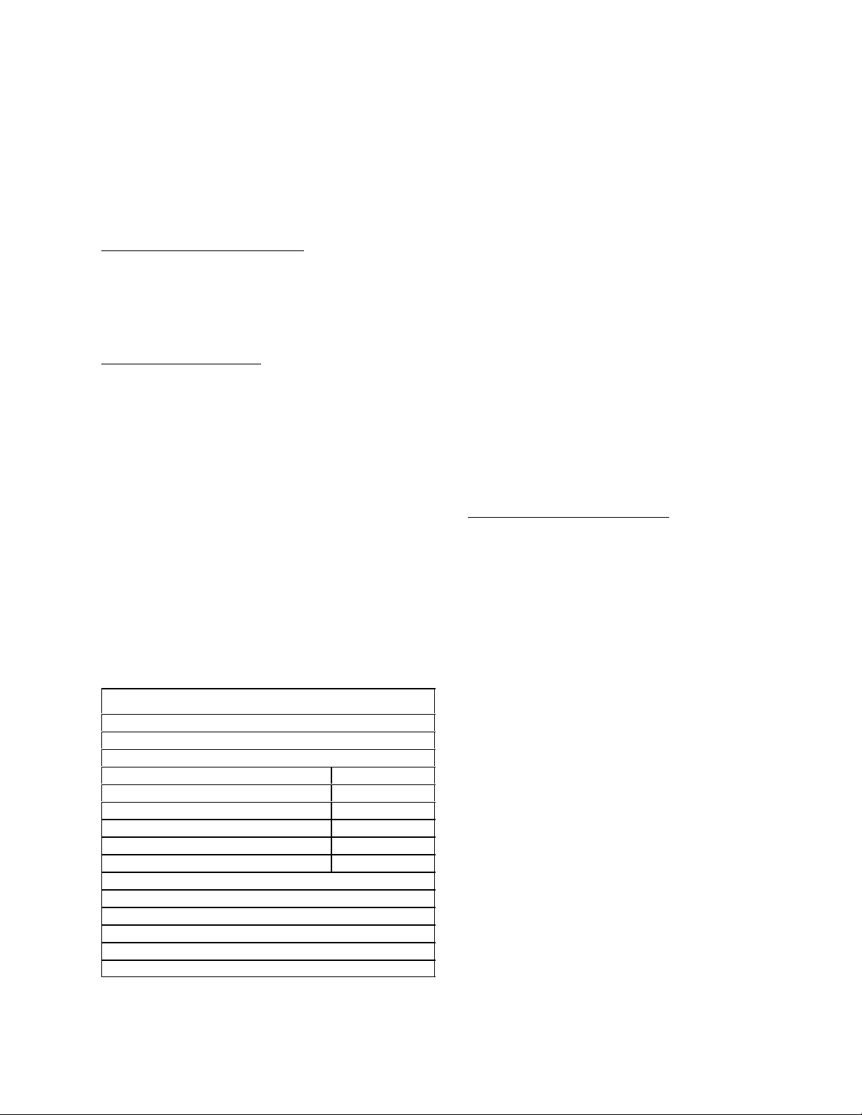
Table 1. Design Data
Unit Part Number 414019–000
Overall Dimensions:
Height without base kit 14–3/8 inches
Height with base kit 16–inches
Width without base kit 1–3/4 inches
Width with base kit 6–1/4 inches
Depth without base kit 4–3/4 inches
Depth with base kit 8–inches
Shipping Weight pounds
Dispensing Rate (continuous) nominal 1–1/2 oz/sec.
Ambient Operating Temperature 40°F to 100°F
FIGURE 1. DRAFT ARM WITH SF-1 VALVE
(SHOWN WITH OPTIONAL BASE KIT)
THEORY OF OPERATION (see Figure 2)
UNIT USED AS A TEA DISPENSER (see Figure
2)
A nitrogen (N) gas cylinder delivers gas through an
adjustable nitrogen gas regulator to the concentrate
tank. Gas pressure exerted upon contents inside
concentrate tank pushes concentrate from tank to
dispensing valve. At the same time, plain water is
pushed by city water line pressure to the dispensing
valve. Concentrate and plain water pass through adjustable water and syrup (concentrate) regulators in
the dispensing valve and meet simultaneously at the
valve nozzle resulting in finished product being dispensed.
UNIT CONNECTED TO A POST–MIX SYSTEM
The unit may be connected into a post–mix system
to dispense a carbonated or a non–carbonated (still
drink). The unit is shipped from the factory with
Baffle Tube Extension (P/N 300097–000) and Baffle
(P/N 318754–011) installed on the dispensing valve
and is intended to dispense tea. If unit will be connected into post–mix system, tube extension and
baffle should be removed and BAFFLE (item 12)
should be installed on valve for better mixing of dispensed product.
1 300168000
Page 6

300168000
WATER SOURCE
SHUTOFF VALVE
FILTER
WATER STRAINER
DRAFT ARM
WATER FILTER INSTALLATION
FOR FILTERS WITHOUT BUILT-IN
WATER SHUTOFF VALVE
PRIMARY REGULATOR
CONCENTRA T E TANK
GAS CHECK VALVE
NITROGEN (N)
CYLINDER
CONCENTRATE
TANK
2
FOR
LINE LEGEND
PLAIN WATER
CO
2
CONCENTRATE
FIGURE 2. FLOW DIAGRAM (TEA SYSTEM)
Page 7

INSTALLATION
This section covers unpacking and inspection, identification of LOOSE–SHIPPED PARTS, selecting location, installing unit, preparing for operation, and operation.
UNPACKING AND INSPECTION
NOTE: The unit was thoroughly inspected before
leaving the factory and the carrier has accepted and
signed for it. Any damage or irregularities should be
noted at time of delivery and immediately reported to
the delivering carrier. Request a written inspection
report from the claims inspector to substantiate any
necessary claim. File claim with delivering carrier, not
with IMI Cornelius Inc.
Table 2. Loose-Shipped Parts
Item
No. Part No. Name Qty.
1 317904–999 Flavor Decal (as
specified by
customer)
2 317905–999 Flavor Decal (as
specified by
customer)
3 311035 Water Strainer Ass’y1
4 176107 Adapter Fitting, 1/4
NPT by 7/16–20
5 178025–100 Tapered Gasket,
White
6 176035 Ferrule 2
7 176034 Nipple 2
8 176017 Nut 2
9 176193 Adapter Fitting,
7/16–20 male by
7/16–20 male
10 311577 Wing Nut 1
11 311584 Tube, Hold–Down 1
12 318523–027 Baffle (post–mix
application)
1
1
2
2
1
1
3. WATER STRAINER ASS’Y (item 3) to be
installed in plain water inlet supply line between
water filter and unit if used as tea unit.
4. ADAPTER FITTINGS (item 4) to be installed in
inlet and outlet of WATER STRAINER ASS’Y
(item 3) prior to installing water strainer if used
as tea unit.
5. TAPERED GASKETS, WHITE (item 5) are used
to seal connections when connecting water inlet
and outlet lines to WATER STRAINER ASS’Y
(item 3) if used as tea unit.
6. NUT (item 8), NIPPLE (item 7), and FERRULE
(item 6) to be installed on ends of unit inlet lines.
7. ADAPTER FITTINGS (item 9) used to connect
line to swivel nut connector on end of unit inlet
line.
8. TUBE, HOLD–DOWN (item 11) to be installed in
bottom of unit, then unit to be secured to countertop with WING NUT (item 10).
9. BAFFLE (item 12) to be installed on dispensing
valve if unit will be installed in post–mix system.
SELECTING LOCATION
This unit may be island–mounted or installed on a
front or rear counter. Locate unit so the following requirements are satisfied.
Close to a cold (100°F max) plain water source capable of supplying water at 20 to 125–psig if used as a
tea unit (see Figure 2). Water inlet supply line should
include a water shutoff valve and a water filter.
Close to a permanent drain for connection of drain
hose if optional Base Kit (P/N 319314–039) will be
used.
INSTALLING UNIT
INSTALLING UNIT WITHOUT BASE
1. Drill 3/4–inch hole in countertop.
IDENTIFICATION OF LOOSE–SHIPPED
PARTS
1. FLAVOR DECAL (item 1) to be installed on
back of dispensing valve cover.
2. FLAVOR DECAL (item 2) to be installed on front
of dispensing valve cover.
2. Route unit inlet lines out through hole in unit
base plate.
3. Route unit inlet lines through TUBE, HOLD–
DOWN (item 11).
4. Slide hold–down tube up on unit inlet lines, then
screw tube into base plate in bottom of unit.
5. Route unit inlet lines and hold–down tube down
through hole in countertop.
3 300168000
Page 8

6. To comply with National Sanitation Foundation
(NSF) requirements, unit base must be sealed
to countertop and all access holes to inside of
unit base must by sealed with Permagum or
other sealant material. Proceed as follows to
seal unit base.
8. To comply with National Sanitation Foundation
(NSF) requirements, unit base must be sealed
to countertop and all access holes to inside of
unit base must be sealed with Permagum or
other sealant material. Proceed as follows to
seal unit base.
A. Tilt unit up to expose bottom of base.
B. Liberally apply silastic sealant such as Dow
Corning RTV 731 or equivalent on base
bottom edges.
NOTE: Do not move unit after positioning or seal
from unit base to countertop will be broken.
C. Lower unit into operating position on coun-
tertop to complete seal from unit base to
countertop.
D. Slide WING NUT (item 10) up on unit inlet
lines to hold–down tube, then secure unit to
countertop with wing nut.
E. Apply additional sealant around bottom of
unit base. Seal must have a minimum radius of 1/2–inch to prevent crevices and to
insure a complete seal.
F. Seal all access holes to inside of unit base
with permagum or other sealant material.
7. Install NUT (item 8), NIPPLE (item 7), and FERRULE (item 6) on ends of unit inlet lines. Crimp
ferrules with IMI Cornelius Inc. crimping tool
(P/N 274261–300) and die set No. 31.
INSTALLING UNIT WITH OPTIONAL BASE
KIT (P/N 319314–039)
1. Tape loose–shipped template in place on coun-
tertop.
2. Drill holes indicated on template in countertop,
then remove template.
3. Route unit inlet lines out through hole in unit
base plate.
4. Route unit inlet lines through TUBE, HOLD–
DOWN (item 11).
5. Slide hold–down tube up on unit inlet lines, then
screw tube into base plate in bottom of unit.
6. Assemble base kit on unit.
7. Route unit inlet lines and drip tray drain hose
through holes in countertop.
A. Tilt unit up to expose bottom of base.
B. Liberally apply silastic sealant such as Dow
Corning RTV 731 or equivalent on base
bottom edges.
NOTE: Do not move unit after positioning or seal
from unit base to countertop will be broken.
C. Lower unit into operating position on coun-
tertop to complete seal from unit base to
countertop.
D. Fasten unit to countertop with loose–
shipped parts.
E. Apply additional sealant around bottom of
unit base. Seal must have a minimum radius of 1/2–inch to prevent crevices and to
insure a complete seal.
9. Install NUT (item 8), NIPPLE (item 7). and FERRULE (item 6) on ends of unit inlet lines. Crimp
ferrules with IMI Cornelius Inc. crimping tool
(P/N274261–300) and die set No. 31.
CONNECTING INLET SUPPLY LINES TO
UNIT
UNIT USED AS TEA UNIT (see Figure 2)
1. Connecting Water Inlet Supply Line.
IMI Cornelius Inc. recommends that a water shutoff
valve and a water filter be installed in the water inlet
supply line connected to unit. A IMI Cornelius Inc.
Water Filter (P/N 313860–000) and Quick Disconnect
Set (P/N 313867–000) are recommended.
NOTE: The unit must be connected to a cold
(100°F max) plain water source capable of supplying water at 20 to 125–psig. A Saddle Valve
(P/N 315664–000) or equivalent may be used to
tap into water source. Connect water inlet supply
line to unit as follows:
A. Install ADAPTER FITTINGS (item 4) in
WATER STRAINER ASS’Y (item 3) inlet
and outlet ports. Seal connections with
thread sealant compound.
B. Install water strainer assembly under coun-
tertop close enough to unit to allow unit water inlet line to be connected.
C. Connect unit water inlet line to water strain-
er assembly outlet fitting. Seal connection
with TAPERED GASKET, WHITE (item 5).
4300168000
Page 9

D. Before connecting water inlet supply line to
water strainer assembly, open water shutoff
valve for a period of time to flush out any
metal shavings resulting from installing fitting or saddle valve.
PREPARING FOR OPERATION
UNIT USED AS A TEA UNIT
1. Open water inlet supply line shutoff valve.
E. Connect water inlet supply line to water
strainer assembly inlet fitting. Seal connection with TAPERED GASKET, WHITE (item
5).
2. Connecting Concentrate Supply Line.
A. Install ADAPTER FITTING (item 9) in end
of unit concentrate inlet line.
B. Connect concentrate supply line from con-
centrate tank location to unit concentrate
inlet line.
UNIT CONNECTED TO POST–MIX
SYSTEM
NOTE: Unit is shipped from factory with Baffle
Tube Extension (P/N 300097–000) and Baffle (P/N
318754–011) installed on dispensing valve and is
intended for dispensing of tea. Remove tube extension and baffle and install BAFFLE (item 12)
for post–mix dispensing.
Connecting Water Inlet Supply Line.
Connect carbonated water for carbonated drink or
plain water for non–carbonated (still drink) water inlet
supply line from post–mix system to unit water inlet
supply line. Seal connection with TAPERED GASKET, WHITE (item 5).
Connecting Syrup Inlet Supply Line.
Connect syrup inlet supply line from post–mix system
to unit syrup inlet supply line. Seal connection with
TAPERED GASKET, WHITE (item 5).
2. Dispense from dispensing valve until air is
purged from water system. Check system for
leaks and tighten or repair any loose connections.
3. Check, and if necessary, adjust dispensing
valve for proper water flow rate as instructed.
4. Adjust concentrate tank nitrogen regulator as
instructed.
5. Connect concentrate tank into system.
6. Dispense from dispensing valve until air is
purged from concentrate system. Check for
leaks and tighten or repair any loose connections.
7. Install FLAVOR DECALS (items 1 and 2) on
dispensing valve cover.
UNIT CONNECTED TO A POST–MIX SYSTEM
1. Adjust post–mix system carbonator and syrup
tanks CO2 regulators as instructed.
2. Activate post–mix system carbonated water and
plain water supplies.
3. Dispense from dispensing valve until air is
purged from water system. Check for leaks and
tighten or repair any loose connections.
4. Check and if necessary, adjust dispensing valve
for proper water flow rate as instructed.
5. Activate post–mix system syrup supply.
CONNECTING (IF USED) DRIP TRAY
DRAIN HOSE TO PERMANENT DRAIN
NOTE: Drip tray drain hose routed to a waste container is not recommended due to sanitation and
cleaning problems. Connection of drain hose to permanent drain is recommended.
1. Preferably, route lower end of drip tray drain
hose and connect to permanent drain.
2. Place cup rest in drip tray.
6. Dispense from dispensing valve until air is
purged from syrup system. Check for leaks and
tighten or repair any loose connections.
7. Adjust Water–to–Syrup ‘‘Ratio’’ of dispensed
product as instructed.
8. Install FLAVOR DECALS (items 1 and 2) on
dispensing valve cover.
9. Using insulating tape, insulate water and syrup
or concentrate lines up to unit base.
5 300168000
Page 10

THIS PAGE LEFT BLANK INTENTIONALLY
6300168000
Page 11

OPERATORS INSTRUCTIONS
This section covers operators instructions for operating controls, daily pre–operation check, adjustments,
replenishing gas supply and concentrate or syrup
supplies, and cleaning and sanitizing.
DISPENSING VALVE OPERATION (see
Figure 3)
Dispensing valve lever, located below dispensing
valve, need only to be pressed with cup or glass to
dispense product.
DAILY PRE–OPERATION CHECK
1. Tea System Nitrogen Gas Pressure Supply.
Note pressure reading on nitrogen gas pressure
regulator assembly high–side gage which indicates nitrogen cylinder pressure. When high–
side pressure gage reading approaches low–
side gage operating pressure reading, nitrogen
cylinder is almost empty and should be replaced.
Unit Connected to a Post–Mix System.
Water–to–Syrup ‘‘Ratio’’ of dispensed product should
be checked periodically and if necessary, adjusted as
instructed.
ADJUSTING GAS PRESSURE REGULATOR
Tea System.
Concentrate Tank Nitrogen Gas Pressure Regulator
–Nitrogen gas pressure regulator should be checked
periodically for proper pressure setting and if necessary, adjusted as instructed.
Post–Mix System.
Syrup tanks CO2 Gas Pressure Regulator – Syrup
tanks CO2 gas pressure regulator should be checked
periodically for proper pressure setting and if necessary, adjusted as instructed.
Carbonator CO2 Gas Pressure Regulator – Carbonator CO2 gas pressure regulator should be checked
periodically for proper pressure setting and if necessary, adjusted as instructed.
REPLENISHING GAS SUPPLY
Post–Mix System CO2 Gas Pressure Supply.
Make sure CO2 cylinder gas pressure regulator
assembly 1800–psi gage indicator is not in
shaded (‘‘change CO2 cylinder’’) portion of dial.
If so, CO2 cylinder is almost empty and must be
replaced.
2. Sufficient concentrate (tea) or syrup (post–mix).
If not, replenish concentrate or syrup supply.
3. If unit is equipped with base kit, make sure drip
tray is clean and cup rest is in place in drip tray.
ADJUSTMENTS
ADJUSTING DISPENSING VALVE WATER
FLOW RATE
Amount of water dispensed in four seconds should
be approximately five–ounces. If necessary to adjust
water flow rate, adjust as instructed.
ADJUSTING WATER–TO–CONCENTRATE
(TEA) OR SYRUP (POST–MIX) ‘‘RATIO’’ OF
DISPENSED PRODUCT
TEA SYSTEM
Nitrogen gas supply should be checked daily and if
necessary, replenished as instructed.
POST–MIX SYSTEM
CO2 gas supply should be checked daily and if necessary, replenished as instructed.
REPLENISHING CONCENTRATE (TEA
SYSTEM) OR SYRUP (POST–MIX
SYSTEM) SUPPLY
Concentrate (tea system) or syrup (post–mix system)
supply should be checked daily and if necessary, replenished as instructed.
CLEANING AND SANITIZING
DAILY CLEANING OF UNIT
Daily cleaning of unit should be performed at end of
daily operation as instructed.
WEEKLY CLEANING OF DISPENSING VALVE
Dispensing valve should be cleaned at least once a
week as instructed.
Unit Used as a Tea Dispenser.
Water–to–Concentrate ‘‘Ratio’’ of dispensed product
should be checked periodically and if necessary, adjusted as instructed.
SANITIZING SYSTEM
System should be sanitized as instructed every 90
days following Sanitizer Manufacturer’s recommendations.
7 300168000
Page 12

SERVICING WATER STRAINER SCREEN
(TEA SYSTEM)
CLEANING SYSTEM GAS CHECK VALVE (see Figure 2 and 6)
The water strainer screen (see Figure 2 and 5) must
be inspected and serviced at least once a year under
normal circumstances and after any disruptions
(plumbing work, earthquake, etc.) to the water supply
system that might cause turbulent (erratic) flow of
water through the system. Service water strainer
screen as instructed.
The CO2 system gas check valve must be inspected
and serviced at least once a year under normal
conditions and after any CO2 system servicing or
disruption as instructed.
8300168000
Page 13

SERVICE AND MAINTENANCE
This section covers service and maintenance procedures to be performed on the unit.
IMPORTANT: Only qualified personnel should
service unit or system components.
PERIODIC INSPECTION
1. Check dispensing valve for dripping that indicates a leak and repair as necessary.
2. Check concentrate (tea system) or syrup (post–
mix system) supply and if necessary, replenish
as instructed.
3. Tea System Nitrogen Gas Pressure Supply.
Note pressure reading on nitrogen gas pressure
regulator assembly high–side gage which indicates nitrogen cylinder pressure. When high–
side pressure gage reading approaches low–
side gage operating pressure reading, nitrogen
cylinder is almost empty and should be replaced
as instructed.
Post–Mix System Gas Pressure Supply.
Make sure CO2 cylinder gas regulator assembly
1800–psi gage indicator is not in shaded
(‘‘change CO2 cylinder’’) portion of dial. If so,
CO2 cylinder is almost empty and must be replaced as instructed.
ADJUSTMENTS
ADJUSTING DISPENSING VALVE WATER
FLOW RATE
1. Remove quick disconnect from concentrate (tea
system) or syrup (post–mix system) tank outlet.
2. Loosen dispensing valve cover screw until
screw disengages from valve, then remove cover.
3. Hold large chamber of ratio cup under dispensing nozzle.
4. Open dispensing valve for exactly four seconds.
Approximately 5–ounces of water should have
been dispensed in ratio cup.
(see Figure 4)
ADJUSTING WA TER–TO–CONCENTRATE
(TEA SYSTEM) OR SYRUP (POST–MIX
SYSTEM) “RATIO’’ OF DISPENSED
PRODUCT (see Figure 4)
NOTE: Make sure dispensing valve water flow
rate is as desired before adjusting valve for Water–to–Concentrate or Syrup ‘‘Ratio’’ of dispensed product.
Adjust Water–to–Concentrate (tea) or syrup (post–
mix) ‘‘Ratio’’ of dispensed product by using ‘‘Ratio’’
Cup (P/N 311100–000) and Syrup Diversion Tube
Assembly (P/N 319540–000) as follows (see Figure
4).
1. Loosen dispensing valve cover screw until
screw disengages from valve, then remove cover.
2. Install syrup diversion tube assembly on dispensing valve by pushing rubber end of syrup
diversion tube up on baffle inside nozzle.
NOTE: Refer to concentrate (tea) or syrup (post–
mix) manufacturer’s recommendations on package for Water–to–Concentrate (tea) or syrup
(post–mix)
‘‘Ratio’’.
3. Hold container under dispensing valve. Open
dispensing valve and dispense just enough to fill
syrup diversion tube with syrup or concentrate.
4. Hold large chamber of ratio cup under dispensing valve nozzle. Place free end of syrup diversion tube into syrup chamber marked for proper
ratio. Open dispensing valve and dispense
approximately five ounces of water into ratio
cup. Water and syrup or concentrate levels
should be even in ratio cup.
5. If water and syrup or concentrate levels are not
even in ratio cup, turn dispensing valve syrup
flow regulator labeled ‘‘SYRUP’’ adjusting screw
to the left (counterclockwise) no more than
1/4–turn at a time for less syrup or concentrate
or to the right (clockwise) no more than 1/4–turn
at a time for more syrup or concentrate.
5. If amount of water dispensed in four seconds
was incorrect, turn dispensing valve water flow
regulator labeled ‘‘WATER’’ adjusting screw to
the left (counterclockwise) no more than
1/4–turn at a time for less water or to the right
(clockwise) for more water.
6. Test for amount of water dispensed and adjust
dispensing valve water flow regulator until proper amount of water is dispensed.
6. Repeat Water–to–Concentrate (tea) or syrup
(post–mix) ‘‘Ratio’’ test and adjust syrup flow
regulator as many times as necessary until
proper ratio of dispensed drink is achieved.
7. Remove syrup diversion tube assembly from
dispensing valve.
8. Install dispensing valve cover and secure with
screw.
9 300168000
Page 14

COVER
COVER RETAINING
SCREW
DISPENSING
VALVE
DISPENSING
LEVER
CUP
REST
ADJUSTABLE WATER
FLOW REGULATOR
ADJUSTABLE CONCENTRATE
OR SYRUP FLOW REGULATOR
COUPLING NUT
OPTIONAL BASE KIT
(P/N 319314-039)
FIGURE 3. PARTS IDENTIFICATION (SHOWN WITH OPTIONAL BASE KIT)
ADJUSTING GAS PRESSURE REGULATOR
Tea System. (see Figure 2)
Set concentrate tank nitrogen gas regulator at 30–psi
plus one pound for every five feet over ten feet of
concentrate line length and one pound for every two
feet of vertical lift. For example: If total concentrate
line length is 20 feet and total vertical lift is 6 feet,
then 30–psi (initial) + 2–psi (1 pound for every 5 feet
over 10 feet of length which is 20 feet) + 3–psi (1
pound for every 2 feet of vertical lift which is 6 feet);
total equal 35–psi nitrogen regulator setting.
Post–Mix System.
Syrup tanks CO2 Regulator
Adjust syrup tanks CO2 regulator at 40–psig for syr-
up lines up to 10–feet in length plus one pound for
each 2–feet of vertical lift. For example: if syrup line
total length is 30–feet and total vertical lift is 6–feet,
then 40–psig + 2–psig (1–pound for every 10–feet of
length over 10–feet which is 20–feet) + 3–psig
(1–pound for every 2–feet of vertical lift which is
6–feet); total 40 + 2 + 3 = 45–psig CO2 regulator setting.
Carbonator CO2 Regulator.
Refer to manual provided with remote carbonator to
adjust carbonator CO2 regulator operating pressure.
REPLENISHING GAS SUPPLY
TEA SYSTEM
NOTE: Note pressure reading on nitrogen gas
pressure regulator assembly high–side gage
which indicates nitrogen cylinder pressure.
When high–side pressure gage reading approaches low–side gage operating pressure
reading, nitrogen cylinder is almost empty and
should be replaced.
1. Fully close (clockwise) nitrogen cylinder valve
shutoff valve.
2. Slowly loosen nitrogen regulator assembly coupling nut allowing nitrogen pressure to escape,
then remove regulator from empty nitrogen cylinder.
3. Unfasten safety chain and remove empty nitrogen cylinder.
4–2
300168–000
10300168000
Page 15

*Baffle (item 12) p/n 318523-027 is used
for post-mix application.
ADJUSTABLE WATER
FLOW REGULATOR
ADJUSTABLE SYRUP OR
CONCENTRA TE FLOW
REGULATOR
SYRUP DIVERSION TUBE
ASS’Y (P/N 319540-000)
RATIO CUP
(P/N 311100-000)
*BAFFLE
BAFFLE
WATER
CHAMBER
NOZZLE
WARNING: To avoid personal injury
and/or property damage, always
secure CO2 cylinder with safety chain
to prevent it from falling over. Should the
valve become accidentally damaged or
broken off, CO2 cylinder can cause serious
personal injury.
3. Position CO2 cylinder and secure with safety
chain.
4. Make sure gasket is in place inside CO2 regulator coupling nut, then install regulator on CO
2
cylinder.
5. Open (counterclockwise) CO2 cylinder valve
slightly to allow lines to slowly fill with gas, then
open valve fully to back–seat valve. (Back–seat-
ing valve prevents leakage around valve shaft.)
FIGURE 4. RATIO CUP AND SYRUP DIVERSION
TUBE ASSEMBLY
WARNING: To avoid personal injury
and/or property damage, always
secure nitrogen gas cylinder with
safety chain to prevent it from falling over.
Should the valve become accidentally
damaged or broken off, nitrogen cylinder can
cause serious personal injury.
4. Position nitrogen cylinder and secure with safety
chain.
5. Install nitrogen gas pressure regulator assembly
on nitrogen cylinder.
6. Open (counterclockwise) nitrogen cylinder shutoff valve slightly to allow lines to slowly fill with
gas, then open valve fully to back–seat valve.
(Back–seating valve prevents gas leakage
around valve shaft).
7. Check for nitrogen gas leaks and tighten any
loose connections.
6. Check CO2 connections for leaks. Tighten loose
connections.
REPLENISHING CONCENTRATE (TEA
SYSTEM) OR SYRUP (POST–MIX
SYSTEM) SUPPLY
1. Remove gas disconnect (grey) and syrup or
concentrate disconnect (black) from empty tank,
then remove tank.
2. Place full tank in position, then connect gas disconnect (grey) and syrup or concentrate disconnect (black)to tank.
CONCENTRATE (TEA SYSTEM) OR
SYRUP (POST–MIX SYSTEM) FLAVOR
CHANGE
Sanitize system as instructed, then install full tank of
new flavor concentrate or syrup.
CLEANING AND SANITIZING
DAILY CLEANING OF UNIT (DO NOT USE
ABRASIVE TYPE CLEANERS)
Unit should be thoroughly cleaned at end of daily operation as follows:
POST–MIX SYSTEM
NOTE: When indicator on CO2 cylinder regulator
assembly 1800–psig gage is in shaded (‘‘change
CO2 cylinder’’) portion of dial, CO2 cylinder is
almost empty and should be changed.
1. Fully close (clockwise) CO2 cylinder valve.
2. Slowly loosen CO2 regulator assembly coupling
nut allowing CO2 pressure to escape, then remove regulator assembly from empty CO2 cylinder.
11 300168000
1. If unit is equipped with base kit, remove cup rest
from drip tray. Wash cup rest in plain water, then
wipe dry with a clean soft cloth.
2. Wipe unit exterior and drip tray interior (if applicable) with damp cloth, then wipe dry with clean
soft cloth.
3. Install cup rest in drip tray.
WEEKLY CLEANING OF DISPENSING VALVE
1. Loosen dispensing valve cover screw until
screw disengages from valve, then remove cover.
Page 16

2. Remove nozzle, baffle, and baffle tube extension (if dispensing tea) from dispensing valve.
3. Wash removed parts, including valve cover, in
warm water.
WARNING: Flush sanitizing solution
from system as instructed. Residual
sanitizing solution left in system
could create a health hazard.
WATER STRAINER HOUSING
SCREEN (P/N 313253-000)
O-RING (P/N 310784-000)
SCREEN RETAINER
FIGURE 5. WATER STRAINER
4. Hold appropriate container under dispensing
valve, then slowly pour warm water over valve.
5. Install baffle, baffle tube extension (if applicable), nozzle, and cover on dispensing valve.
SANITIZING UNIT
IMPORTANT: Only qualified personnel should
perform sanitizing procedure.
The unit should be sanitized at least weekly following
Sanitizer Manufacturer’s recommendations. Use
Chlor–Tergent (Oakite Products, Inc.) or equivalent
sanitizer. Proceed as follows to sanitize unit.
1. Remove quick disconnects from concentrate to
syrup tank. Wash quick disconnects in warm
water.
2. Following Sanitizer Manufacturer’s instructions,
prepare two gallons of sanitizing solution in
clean empty concentrate or syrup tank.
7. Place waste container under dispensing valve.
Open valve to permit concentrate or syrup to
purge sanitizing solution from system and until
only syrup is dispensed, then close valve.
WARNING: To avoid possible
personal injury or property damage,
do not attempt to remove tank cover
until gas pressure has been released from
tank.
8. Thoroughly rinse inside and outside of tank that
was used for sanitizing solution to remove all
solution residue.
SERVICING WATER STRAINER SCREEN
(see Figures 2 and 5)
The water strainer screen must be inspected and
serviced at least once a year under normal circumstances and after any disruptions (plumbing work,
earthquake, etc.) to the water supply system that
might cause turbulent (erratic) flow of water through
the system. Service water strainer screen as follows:
1. Close unit water inlet line shutoff valve.
2. Loosen water strainer screen retainer, then pull
screen retainer and screen from water strainer
housing.
3. Pull screen from screen retainer. Clean any sediment from screen retainer and port in water
strainer housing.
4. Inspect screen for holes, restrictions, corrosion,
and other damage. Discard damaged screen.
3. Connect tank containing sanitizing solution into
tea or syrup system.
4. Place waste container under dispensing valve
nozzle. Dispense from dispensing valve to permit sanitizing solution to push concentrate or
syrup out of system and valve. Continue to dispense until only sanitizing solution is dispensed,
then close valve.
5. Follow Sanitizer Manufacturer’s application
instructions.
6. Remove tank containing sanitizing solution and
install tank containing concentrate or syrup into
concentrate or syrup system.
5. Install good or new screen (P/N 313253–000) in
screen retainer, then screw screen retainer into
water strainer housing. Tighten retainer only
finger tight.
6. Open unit water inlet line shutoff valve, then
check for water leaks.
CLEANING GAS CHECK VALVE (see
Figures 2 and 6)
The system gas check valve must be inspected and
serviced at least once a year under normal conditions and after any servicing or disruption of the system. ALWAYS REPLACE QUAD RING SEAL EACH
TIME GAS CHECK VALVES ARE SERVICED.
12300168000
Page 17

QUAD RING
183294-000
BALL
183296-000
SPRING
183297-000
RETAINER
183298-000
BODY
183295-100
*Quad ring seal must be replaced
each time check valve is serviced.
FIGURE 6. GAS CHECK VALVE
REMOVE AND REPLACEMENT
PROCEDURES
DISPENSING VALVE ASSEMBLY (see Figure 3)
Removal.
1. Loosen dispensing valve cover until screw disengages from valve, then remove cover.
2. Using spanner wrench, loosen and remove coupling nut from dispensing valve. Remove dispensing valve from unit.
Installation.
1. Install dispensing valve by reversing removal
procedure. Tighten coupling nut using spanner
wrench.
2. Adjust water flow regulator for water flow rate,
then adjust syrup flow regulator for Water–to–
Concentrate (tea) or syrup (post–mix) ‘‘Ratio’’ of
dispensed product as instructed.
SYRUP, CONCENTRATE, OR WATER FLOW
REGULATOR
Removal.
1. Loosen dispensing valve cover screw until
screw disengages from dispensing valve, then
remove cover.
2. Using spanner wrench, loosen and remove coupling nut from dispensing valve. Remove dispensing valve from unit.
(see Figures 3 and 7)
4. Pull TOP FLOW CONTROL (item 11), SPRING
(item 12), PISTON (item 13) up out of CYLINDER (item 14).
IMPORTANT: If more than one syrup or
concentrate or water flow regulator will be
disassembled at one time, do not mix pistons
and cylinders as they are precision matched
sets.
5. The CYLINDER (item 14) normally need not be
removed from BODY (item 15). If need to remove cylinder should arise, pull cylinder up out
of body, ALWAYS INSTALL NEW O–RING (item
10) P/N 317816–000 ON CYLINDER BEFORE
INSTALLING CYLINDER IN BODY.
Installation.
1. Install TOP FLOW CONTROL (item 11),
SPRING (item 12), and PISTON (item 13) in
CYLINDER (item 14).
2. Secure water flow or syrup or concentrate flow
regulator in dispensing valve BODY (item 15)
with PLATE (item 8) and SCREWS (item 9).
3. Install dispensing valve by reversing removal
procedure. Tighten coupling nut using spanner
wrench.
4. Water Flow Regulator Removed.
If water flow regulator was removed from dis-
pensing valve, water flow rate of valve must be
checked and if necessary, regulator must be
adjusted as instructed.
Syrup or Concentrate Flow Regulator Removed.
If syrup or concentrate flow regulator was re-
moved from dispensing valve, Water–to–Con-
centrate (tea) or syrup (post–mix) ‘‘Ratio’’ of dispensed product must be checked and if
necessary, adjusted as instructed.
5. Install dispensing valve cover and secure with
screw.
INLET VALVE (see Figures 3 and 7)
Removal.
1. Loosen dispensing valve cover screw until
screw disengages from dispensing valve, then
remove cover.
2. Using spanner wrench, loosen and remove coupling nut from dispensing valve. Remove dispensing valve from unit.
3. Turn dispensing valve upside down, then disconnect SPRINGS (item 3) from INLET
VALVES (item 4).
3. Remove two SCREWS (item 9) securing PLATE
(item 8) that secures water flow or syrup or concentrate flow regulator in dispensing valve
BODY (item 15), then remove plate.
13 300168000
4. Remove four SCREWS (item 1) securing dispensing valve BOTTOM COVER (item 2) and
VALVE BLOCK (item 6) to BODY (item 15),
then separate valve block from body.
Page 18

5. Remove inlet valve from valve block.
6. Remove NIB (item 5) from inlet valve.
2. Install dispensing valve by reversing removal
procedure. Tighten coupling nut using spanner
wrench.
NOTE: Short nib is for syrup or concentrate inlet
valve and long nib is for water inlet valve.
Installation.
1. Install inlet valve and assemble dispensing
valve by reversing disassembly procedure.
NOTE: It may be necessary to adjust inlet valves
so water and syrup or concentrate dispensing
start at same time and stop at same time by turning SETSCREWS (item 7).
3. Install dispensing valve cover and secure with
screw.
14300168000
Page 19

1
2
3
4
5
6
7
8
9
10
11
12
13
14
15
16
17
ADJUSTABLE CONCENTRATE OR SYRUP
AND WATER FLOW REGULAT ORS PARTS
TERMINOLOGY ARE THE SAME.
18
19
20
21
22
Item No. Description
1 Screw, Thread Cutting
2 Bottom Cover
3 Spring
4 Inlet Valve
5 Nib, Short, Syrup
Nib, Long, Water
6 Valve Block
7 Setscrew, Hex Socket
8 Plate
9 Screw, Thread Cutting
10 Screw, Thread Cutting
11 Top Flow Control
FIGURE 7. DISPENSING VALVE ASSEMBLY
*BAFFLE (P/n 318523-027), loose-shipped with unit,
is used in post-mix application of unit.
Item No. Description
12 Spring
13 Piston
14 Cylinder
15 Body
16 O–Ring
17 Baffle
18 O–Ring
19 Nozzle
20 Baffle Tube Extension
21 Cover Ass’y
22 Machine Screw
15 300168000
Page 20

FIGURE 8. INSTRUCTIONS FOR CRIMPING TUBE CLAMPS
16300168000
Page 21

TROUBLESHOOTING
IMPORTANT: Only qualified personnel should service internal components or electrical wiring.
WARNING: If repairs are to be made to carbonated water system, disconnect electrical
power to Cooling Unit, shut off plain water and CO2 supplies, and relieve the carbonated
water system pressure before proceeding. If repairs are to be made to syrup system,
remove quick disconnects from applicable syrup tank, then relieve the system pressure before
proceeding. If repairs are to be made to CO2 system, stop dispensing, shut off CO2 supply, then
relieve the system pressure before proceeding.
If repairs are to be made to an existing Remote Condensing unit, disconnect the power to the
condensing unit before proceeding
TROUBLESHOOTING TEA SYSTEM
Trouble Probable Cause Remedy
ONLY WATER DISPENSED. A. Quick disconnects not secure
on concentrate tank.
B. Out of concentrate. B. Replenish concentrate supply as
C. Concentrate tank nitrogen
regulator not properly
adjusted.
D. Inoperable dispensing valve. D. Repair dispensing valve.
E. Dispensing valve concentrate
flow regulator not properly
adjusted.
F. No nitrogen supply. F. Replenish nitrogen supply as
G. Dispensing valve concentrate
flow regulator, concentrate
tank quick disconnect, or
concentrate lines restricted.
IMPORTANT: If necessary to disassemble and clean dispensing valve
flow regulators, do not intermix their pistons and cylinders as they are
precision matched sets.
ONLY CONCENTRATE
DISPENSED.
A. Water inlet supply line shutoff
valve closed.
A. Secure quick disconnects on
concentrate tank.
instructed.
C. Adjust concentrate tank nitrogen
regulator as instructed.
E. Adjust dispensing valve
concentrate flow regulator as
instructed.
instructed.
G. Sanitize concentrate system as
instructed (see IMPORTANT
note).
A. Open water inlet supply line
shutoff valve.
NO CONCENTRATE OR
WATER DISPENSED.
WATER–TO–CONCENTRATE
‘‘RATIO’’ TOO LOW OR TOO
HIGH.
B. Water filter clogged. B. Replace water filter.
C. Water strainer clogged. C. Service water strainer as
instructed.
D. Inoperable dispensing valve. D. Repair dispensing valve.
A. Inoperable dispensing valve. A. Repair dispensing valve.
A. Dispensing valve concentrate
flow regulator not properly
adjusted.
B. Nitrogen gas pressure to
concentrate tanks insufficient
to push concentrate out of
tank.
17 300168000
A. Adjust Water–to–Concentrate
‘‘Ratio’’ as instructed.
B. Adjust nitrogen regulator for
concentrate tanks or replenish
nitrogen supply as instructed.
Page 22

Trouble RemedyProbable Cause
WATER–TO–CONCENTRATE
‘‘RATIO’’ TOO LOW OR TOO
HIGH. (cond’t)
ADJUSTMENT OF
DISPENSING VALVE
CONCENTRATE FLOW
REGULATOR DOES NOT
INCREASE TO DESIRED
WATER–TO–CONCENTRATE
‘‘RATIO’’.
C. Water pressure too low (must
be minimum of 20–psig).
A. No concentrate supply A. Replenish concentrate supply as
B. Concentrate tanks quick
disconnects not secure.
C. Concentrate tank nitrogen
regulator out of adjustment.
D. Dispensing valve concentrate
flow regulator, concentrate
tank quick disconnect, or
concentrate line restricted.
E. Water flowasher obstructed or
tapered nylon washer inside
tube swivel nut connection
distorted from being
over–tightened.
C. Correct water pressure problem.
instructed.
B. Secure concentrate tanks quick
disconnects.
C. Adjust concentrate tank nitrogen
regulator as instructed.
D. Sanitize concentrate system as
instructed.
E. Clean or replace flowasher or
replace tapered nylon washer and
make sure it seats properly.
F. Improper Baume of
concentrate.
G. Dirty or inoperative piston or
spring in dispensing valve
concentrate flow regulator.
IMPORTANT: If necessary to disassemble and clean dispensing valve
flow regulators, do not intermix their pistons and cylinders as they are
precision matched sets.
ADJUSTMENT OF
DISPENSING VALVE
CONCENTRATE FLOW
REGULATOR DOES NOT
DECREASE TO DESIRED
WATER–TO–CONCENTRATE
‘‘RATIO’’.
A. Dirty or inoperative piston or
spring in dispensing valve
concentrate flow regulator.
B. Water pressure too low (must
be minimum of 20–psig).
IMPORTANT: If necessary to disassemble and clean dispensing valve
flow regulators, do not intermix their pistons and cylinders as they are
precision matched sets.
TROUBLESHOOTING POST–MIX SYSTEM
F. Replace concentrate supply as
instructed.
G. Disassemble and clean
dispensing valve concentrate flow
regulator (see IMPORTANT note).
A. Disassemble and clean
dispensing valve concentrate flow
regulator (see IMPORTANT note).
B. Correct water pressure problem.
WATER–TO–SYRUP ‘‘RATIO’’
TOO LOW OR TOO HIGH.
A. Dispensing valve syrup flow
regulator not properly
adjusted.
B. CO2 gas pressure to syrup
tank insufficient to push syrup
out of tank.
18300168000
A. Adjust Water–to–Syrup ‘‘Ratio’’ as
instructed.
B. Adjust syrup tank CO2 regulator
as instructed.
Page 23

Trouble RemedyProbable Cause
ADJUSTMENT OF
DISPENSING VALVE SYRUP
FLOW REGULATOR DOES
NOT INCREASE TO DESIRED
WATER–TO–SYRUP ‘‘RATIO’’.
A. No syrup supply. A. Replenish syrup supply as
instructed.
B. Syrup tank quick disconnects
B. Secure quick disconnects.
not secure.
C. Syrup tank CO2 regulator out
of adjustment.
D. Dispensing valve syrup flow
regulator, syrup tank quick
C. Adjust syrup tank CO2 regulator
as instructed.
D. Sanitize syrup system as
instructed.
disconnect, or syrup line
restricted.
E. Improper syrup Baume. E. Replace syrup supply as
instructed.
F. Dirty or inoperative piston or
spring in dispensing valve
syrup flow regulator.
F. Disassemble and clean
dispensing valve syrup flow
regulator (see IMPORTANT,
note).
G. Tapered nylon washer inside
tube swivel nut connector
G. Replace nylon washer and make
sure it seats properly.
distorted from being
overtightened.
ADJUSTMENT OF
DISPENSING VALVE SYRUP
FLOW REGULATOR DOES
NOT DECREASE TO
DESIRED
WATER–TO–SYRUP ‘‘RATIO’’.
DISPENSED PRODUCT
CARBONATION TOO LOW.
IMPORTANT: If necessary to disassemble and clean dispensing valve
flow regulators, do not intermix their pistons and cylinders as they are
precision matched sets.
A. Dirty or inoperative piston or
spring in dispensing valve
syrup flow regulator.
A. Disassemble and clean
dispensing valve syrup flow
regulator (see IMPORTANT,
note).
IMPORTANT: If necessary to disassemble and clean dispensing valve
flow regulators, do not intermix their pistons and cylinders as they are
precision matched sets.
A. Carbonator CO2 regulator out
of adjustment for existing
water conditions or
A. Adjust carbonator CO2 regulator
(Reference manual provided with
carbonator).
temperature.
B. Air in carbonator tank. B. Vent air out of carbonator tank
through relief valve. Actuate
dispensing valve to make
carbonator pump cycle on.
C. Water, oil, or dirt, in CO
supply.
2
C. Remove contaminated CO2.
Clean CO2 system (lines,
regulators, etc.) using mild
detergent. Install clean CO
2
supply.
19 300168000
Page 24

Trouble RemedyProbable Cause
DISPENSED PRODUCT
COMES OUT OF
DISPENSING VALVE CLEAR
BUT FOAMS IN CUP OR
GLASS.
DISPENSED PRODUCT
PRODUCES FOAM AS IT
LEAVES DISPENSING VALVE.
A. Oil film or soap scum in cup or
A. Use clean cups and glasses.
glass.
B. Ice used for finished drink is
sub–cooled.
B. Do not use ice directly from
freezer. Allow ice to become ‘‘wet’’
before using. (Refer to following
NOTE).
NOTE: Crushed ice also causes dispensing problems. When finished
drink hits sharp edges of ice, carbonation is released from dispensed
drink.
A. Recovery rate of refrigeration
A. Allow ice bank to recover.
unit exceeded, ice bank
depleted.
B. Carbonator CO2 regulator
pressure adjusted too high for
existing water conditions or
B. Reduce carbonator CO2 regulator
pressure setting. Reference
manual provided with carbonator.
temperature.
C. Syrup over–carbonated with
CO2 as indicated by bubbles in
inlet syrup lines.
C. Remove syrup tanks quick
disconnects shake tank
vigorously, then relieve tank CO
pressure as many times as
necessary to remove
over–carbonation.
2
ONLY CARBONATED WATER
DISPENSED.
D. Dispensing valve restricted or
dirty.
E. Tapered nylon washer inside
carbonated water line swivel
D. Sanitize syrup system as
instructed.
E. Replace nylon washer. Make sure
it is properly seated.
nut connector distorted
restricting carbonated water
flow.
F. Dirty water supply. F. Check water filter. Replace
cartridge. (see NOTE)
NOTE: If water supply is dirty, be sure to flush lines and carbonator
completely. It may be necessary to remove lines to carbonator tank,
invert tank, and flush tank and all inlet lines to remove any foreign
particles or dirt.
A. Quick disconnects not secure
on syrup tank.
A. Secure quick disconnects on
syrup tank.
B. Out of syrup. B. Replenish syrup supply as
instructed.
C. Syrup tank CO2 regulator not
properly adjusted.
C. Adjust syrup tank CO2 regulator
as instructed.
D. Inoperable dispensing valve. D. Repair dispensing valve.
E. Dispensing valve syrup flow
regulator not properly
adjusted.
20300168000
E. Adjust dispensing valve syrup
flow regulator (Water–to–Syrup
‘‘Ratio’’) as instructed.
Page 25

Trouble RemedyProbable Cause
ONLY CARBONATED WATER
DISPENSED. (cont’d)
ONLY SYRUP DISPENSED. A. Water inlet supply line shutoff
F. Dispensing valve syrup flow
regulator, syrup tank quick
disconnect, or syrup lines
restricted.
IMPORTANT: If necessary to disassemble and clean dispensing valve
syrup flow regulators, do not intermix their pistons and cylinders as
they are precision matched sets.
valve closed.
B. Carbonator power cord
unplugged from electrical
outlet.
C. Carbonator CO2 regulator not
properly adjusted.
F. Sanitize syrup system as
instructed. (See IMPORTANT,
note).
A. Open water inlet supply line
shutoff valve.
B. Plug carbonated power cord into
electrical outlet.
C. Adjust carbonator CO2 regulator
(Reference manual provided with
carbonator).
21 300168000
Page 26

THIS PAGE LEFT BLANK INTENTIONALLY
22300168000
Page 27

ILLUSTRATED PARTS BREAKDOWN
DRAFT ARM WITH SF-1 VALVE
IMI CORNELIUS INC.
One Cornelius Place
Anoka, MN. 55303–1592
Telephone (800) 238–3600
Facsimile (612) 422–3232
Model Numbers
414019
September 12, 1983
Revised: October 8, 1986
IMI Cornelius Inc. 1983-86
23
Page 28

10
11
12
13
16
19
23
1
2
3
4
5
6
7
8
9
14
15
17
18
20
21
22
24
25
26
27
28
29
30
31
32
33
34
35
36
37
38
39
40
41
ITEM
NO.
1 176193 Fitting, 7/16–20
2 176034 Nipple
3 176017 Swivel Nut, 7/16–20
4 176035 Ferrule
5 176107 Fitting, 1/4 NPT by 7/16–20
6 178025–100 Tapered Gasket, White
7 311035 Strainer
8 311577 Wing Nut, 3/4–16
9 311584 Tube Hold Down
10 311580 Housing Cover
11 317884 Cover Ass’y (includes 12–14)
12 317881 Retaining Washer
13 317882 Machine Screw, Fl Sl Hd, Stainless
14 317647 Cover
15 319200 Dispensing Valve Ass’y (see
16 *187244 Machine Screw, Sl Pan Hd,
17 150199 Coupling Nut
18 319198 Adapter, Valve
**Zinc–plated steel unless indicated otherwise.
**Sold in bulk quantity only.
PART
NO.
319201 Draft Arm Ass’y, Tea
Steel, No. 8–32 by 3/8–in.
Figure 6–2)
No. 6–32 by 1/4–in.
NAME
FIGURE 9. TEA DRAFT ARM ASSEMBLY
ITEM
NO.
19 319199 Housing Ass’y (includes 20–27)
20 319197 Manifold and Tube Ass’y
21 150058 O–Ring, .301 I.D.
22 180020 Spring
23 178019 Retainer Washer
24 180018–013 Seal
25 314224 Stem, Poppet
26 180025 O–Ring, .364 I.D.
27 314488 Housing
28 316541 Column
29 319314–039 Base Kit, Optional (includes 30–41)
30 151447 Cup Rest
31 140133 Drain Hose Clamp
32 **140598 Drain Hose, 1/2 I.D. by 36–in.
33 319313 Flange
34 319315 Gasket, Rubber
35 *150774 Wing Nut, 3/8–16
36 151140 Mounting Clip
37 *150777 Hex Nut, Jam, 3/8–16
38 150447 Flat Washer, Rubber
39 *150724 Carriage Bolt, 3/8–16 by 5–in.
40 311587 Reinforcing Plate
41 151718–039 Base
PART
NO.
NAME
24300168000
Page 29

1
18
21
23
10
11
12
13
14
16
17
19
20
25
15
22
24
3
2
4
5
6
7
8
9
26
27
28
29
30
31
32
33
34
ITEM
NO.
1 317884 Cover Ass’y, w/o Lever , (includes 2–4)
2 317882 Machine Screw, Fl Sl Hd, Stainless
3 317881 Retaining Washer
4 317647 Cover, w/o Lever, Manual
5 317828 Thread Cutting Screw, Phil Rd Hd,
6 317718 Cover, B o t t o m
7 317649 Nozzle
8 300097 Extension, Baffle (tea application)
9 318754–011 Baffle (tea application)
10 398033–013 O–Ring, .799 I.D. by .103 C.S.
11 317723 Spring
12 311355 Valve Inlet
13 310788 Nib, Short, Syrup
14 317639 Valve Block
15 *314813 Setscrew, Headless Hex Soc.
16 317819 Pin
17 317646 Lever
NOTE 1: Items 27 and 28 are a matched pair and cannot be inter–
changed. Order item 26 for replacement.
**Zinc–plated steel unless indicated otherwise.
**Sold in bulk quantity only.
PART
NO.
319200 Post–Mix Valve Ass’y, Tea Draft Arm
Steel, No. 8–32 by 3/8–in.
Stainless Steel, No. 6–32 by 3/4–in.
318523–027 Baffle (see NOTE 2)
317782 Nib, Long, Water
Oval Pt., No. 8–32 by 1/2–in.
NAME
ITEM
NO.
18 317895 Thread Cutting Screw, Phil Pan Hd,
19 317645 Block, Threaded
20 317714 Plate
21 317784 Thread Cutting Screw, Phil Truss Hd,
22 310632–007 Adjusting Screw
23 180025 O–Ring, .364 I.D. by .070 C.S.
24 317429 Top, Flow Control
25 317816 O–Ring
26 310482 Spring
27 318664 Cylinder and Piston Ass’y, Syrup
28
29 317431 Cylinder (see NOTE 1)
30 317633 Body
31 319540 By–Pass Ass’y (includes 32 and 33)
32 319539 Nozzle
33 318755 Tube, By–Pass
34 319541 O–Ring, .157 I.D. by .038 C.S.
NOTE 2: If unit will be connected to post–mix system, remove existing tea baffle and baffle tube extension and install Baf fle (P/N
318523–000)
PART
NO.
Stainless Steel, No. 10–32 by 1/2–in.
Stainless Steel, No. 8–32 by 5/16–in.
(includes 28 and 29)
318665 Cylinder and Piston Ass’y, Water
(includes 28 and 29)
310754 Piston, Water (see NOTE 1)
310480 Piston, Syrup (see NOTE 1)
NAME
25
300168000
Page 30

THIS PAGE LEFT BLANK INTENTIONALLY
26300168000
Page 31

WARRANTY
IMI Cornelius Inc. warrants that all equipment and parts are free from defects in material and workmanship under normal use and service. For a copy of the warranty applicable to your Cornelius, Remcor or
Wilshire product, in your country, please write, fax or telephone the IMI Cornelius office nearest you.
Please provide the equipment model number, serial number and the date of purchase.
IMI Cornelius Offices
AUSTRALIA D P.O. 210, D RIVERWOOD, D NSW 2210, AUSTRALIA D (61) 2 533 3122 D FAX (61) 2 534 2166
D AM LANGEN FELDE 32 D A-1222 D VIENNA, AUSTRIA D (43) 1 233 520 D FAX (43) 1-2335-2930
AUSTRIA
D BOSKAPELLEI 122 D B-2930 BRAASCHAAT, BELGIUM D (32) 3 664 0552 D FAX (32) 3 665 2307
BELGIUM
D RUA ITAOCARA 97 D TOMAS COELHO D RIO DE JANEIRO, BRAZIL D (55) 21 591 7150 D FAX (55) 21 593 1829
BRAZIL
ENGLAND
D TYTHING ROAD ALCESTER D WARWICKSHIRE, B49 6 EU, ENGLAND D (44) 789 763 101 D FAX (44) 789 763 644
D 71 ROUTE DE ST. DENIS D F-95170 DEUIL LA BARRE D PARIS, FRANCE D (33) 1 34 28 6200 D FAX (33) 1 34 28 6201
FRANCE
GERMANY
GREECE
HONG
ITALY
NEW
SINGAPORE
SPAIN
USA
D CARL LEVERKUS STRASSE 15 D D-4018 LANGENFELD, GERMANY D (49) 2173 7930 D FAX (49) 2173 77 438
D 488 MESSOGION AVENUE D AGIA PARASKEVI D 153 42 D ATHENS, GREECE D (30) 1 600 1073 D FAX (30) 1 601 2491
KONG D 1104 TAIKOTSUI CENTRE D 11-15 KOK CHEUNG ST D TAIKOKTSUE, HONG KONG D (852) 789 9882 D FAX (852) 391 6222
D VIA PELLIZZARI 11 D 1-20059 D VIMARCATE, ITALY D (39) 39 608 0817 D FAX (39) 39 608 0814
ZEALAND D 20 LANSFORD CRES. D P.O. BOX 19-044 AVONDALE D AUCKLAND 7, NEW ZEALAND D (64) 9 8200 357 D FAX (64) 9 8200 361
D 16 TUAS STREET D SINGAPORE 2263 D (65) 862 5542 D FAX (65) 862 5604
D POLIGONO INDUSTRAIL D RIERA DEL FONOLLAR D E-08830 SANT BOI DE LLOBREGAT D BARCELONA, SPAIN D (34) 3 640 2839 D FAX (34) 3 654 3379
D ONE CORNELIUS PLACE D ANOKA, MINNESOTA D (612) 421-6120 D FAX (612) 422-3255
LD004
4/21/98
27
 Loading...