

Page 1
Adjustment, Operation,
and Maintenance Manual
SF-1 AND GEMINI
POST-MIX DISPENSING
VALVES
Part No. 319006000
April 13, 1982
Revised: August 3, 1992
THIS DOCUMENT CONTAINS IMPORTANT INFORMATION
This Manual must be read and understood before installing or operating this equipment
IMI CORNELIUS INC; 1982-92
PRINTED IN U.S.A
Page 2

TABLE OF CONTENTS
GENERAL INFORMATION 1. . . . . . . . . . . . . . . . . . . . . . . . . . . . . . . . . . . . . . . . . . . . . . . . . .
SAFETY INFORMATION 1. . . . . . . . . . . . . . . . . . . . . . . . . . . . . . . . . . . . . . . . . . . . . . .
RECOGNIZE SAFETY INFORMATION 1. . . . . . . . . . . . . . . . . . . . . . . . . . . . . . .
UNDERSTAND SIGNAL WORDS 1. . . . . . . . . . . . . . . . . . . . . . . . . . . . . . . . . . . .
FOLLOW SAFETY INSTRUCTIONS 1. . . . . . . . . . . . . . . . . . . . . . . . . . . . . . . . .
WARRANTY REGISTRATION DATA 2. . . . . . . . . . . . . . . . . . . . . . . . . . . . . . . . .
GENERAL WARRANTY POLICY 2. . . . . . . . . . . . . . . . . . . . . . . . . . . . . . . . . . . . . . . .
TERMS AND CONDITIONS 2. . . . . . . . . . . . . . . . . . . . . . . . . . . . . . . . . . . . . . . . . . . . .
ORDERING INFORMATION 2. . . . . . . . . . . . . . . . . . . . . . . . . . . . . . . . . . . . . . . . . . . .
SHIPPING INFORMATION 3. . . . . . . . . . . . . . . . . . . . . . . . . . . . . . . . . . . . . . . . . . . . . .
COMPLETE SERVICE 3. . . . . . . . . . . . . . . . . . . . . . . . . . . . . . . . . . . . . . . . . . . . . . . . .
HOME OFFICES AND MANUFACTURING 3. . . . . . . . . . . . . . . . . . . . . . . . . . . . . . . .
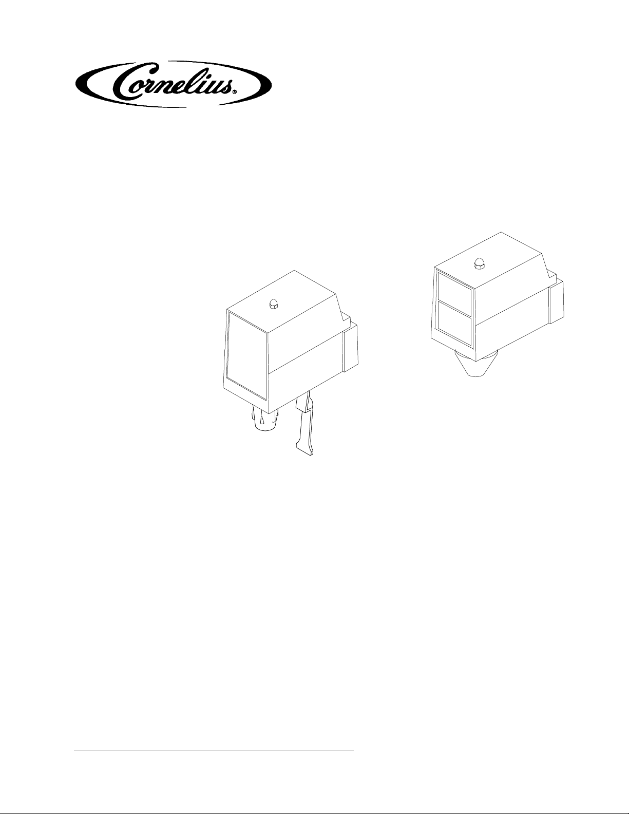
CORNELIUS ELECTRIC SF-1 (SUPER FLOW - 1) AND GEMINI TWO-FLAVOR
POST-MIX DISPENSING VALVES 5. . . . . . . . . . . . . . . . . . . . . . . . . . . . . . . . . . . . . . . . . . .
SF-1 DISPENSING VALVES 5. . . . . . . . . . . . . . . . . . . . . . . . . . . . . . . . . . . . . . . .
GEMINI DISPENSING VALVE (TWO-FLAVOR) 5. . . . . . . . . . . . . . . . . . . . . . . .
ADJUSTMENTS 7. . . . . . . . . . . . . . . . . . . . . . . . . . . . . . . . . . . . . . . . . . . . . . . . . . . . . . . . . . .
Page
INTRODUCTION 7. . . . . . . . . . . . . . . . . . . . . . . . . . . . . . . . . . . . . . . . . . . . . . . . . . . . . .
WATER FLOW RATE 7. . . . . . . . . . . . . . . . . . . . . . . . . . . . . . . . . . . . . . . . . . . . . . . . . . .
DISPENSING VALVE WITH WATER FLOWASHER. 7. . . . . . . . . . . . . . . . . . .
DISPENSING VALVE WITH ADJUSTABLE WATER FLOW REGULATOR. 7
WATER-TO-SYRUP ‘‘RATIO’’ OF DISPENSED PRODUCT 7. . . . . . . . . . . . . . . . . .
SF-1 SINGLE-FLAVOR DISPENSING VALVE. 7. . . . . . . . . . . . . . . . . . . . . . . .
GEMINI TWO-FLAVOR DISPENSING VALVE. 8. . . . . . . . . . . . . . . . . . . . . . . .
ADJUSTING SF-1 DISPENSING VALVE PORTION CONTROL FOR SIZE OF
DRINK DISPENSED 8. . . . . . . . . . . . . . . . . . . . . . . . . . . . . . . . . . . . . . . . . . . . . . . . . . .
OPERATION 11. . . . . . . . . . . . . . . . . . . . . . . . . . . . . . . . . . . . . . . . . . . . . . . . . . . . . . . . . . . . . .
SF-1 DISPENSING VALVE 11. . . . . . . . . . . . . . . . . . . . . . . . . . . . . . . . . . . . . . . . . . . . . .
STANDARD SF-1 ELECTRIC DISPENSING VALVE. 11. . . . . . . . . . . . . . . . . . .
SF-1 DISPENSING VALVE WITH SELF-SERVE DISPENSE SWITCH. 11. . .
SF-1 DISPENSING VALVE WITH PORTION CONTROL. 11. . . . . . . . . . . . . . .
GEMINI TWO-FLAVOR DISPENSING VALVE 11. . . . . . . . . . . . . . . . . . . . . . . . . . . . .
SERVICE AND MAINTENANCE 13. . . . . . . . . . . . . . . . . . . . . . . . . . . . . . . . . . . . . . . . . . . . .
REMOVAL AND REPLACEMENT PROCEDURES ON SF-1 VALVE 13. . . . . . . . . .
REMOVE AND REPLACE SOLENOID COIL (ITEM 12) 13. . . . . . . . . . . . . . . . .
REMOVE AND REPLACE MICRO SWITCH (ITEM 13) 13. . . . . . . . . . . . . . . . .
REMOVE AND REPLACE SYRUP OR WATER FLOW REGULATOR 13. . . .
REMOVE AND REPLACE WATER FLOWASHER ASS’Y 15. . . . . . . . . . . . . . .
REMOVE AND REPLACE INLET VALVE 16. . . . . . . . . . . . . . . . . . . . . . . . . . . . .
REMOVE AND REPLACE PORTION CONTROL MODULE 17. . . . . . . . . . . . .
REMOVE AND REPLACE SELF-SERVE DISPENSE SWITCH MODULE 17.
REMOVAL AND REPLACEMENT PROCEDURE ON GEMINI TWO-FLAVOR
DISPENSING VALVE 17. . . . . . . . . . . . . . . . . . . . . . . . . . . . . . . . . . . . . . . . . . . . . . . . . . .
i
319006000
Page 3

TABLE OF CONTENTS (cont’d)
REMOVE AND REPLACE SYRUP OR WATER SOLENOID AND COIL
ASS’Y 17. . . . . . . . . . . . . . . . . . . . . . . . . . . . . . . . . . . . . . . . . . . . . . . . . . . . . . . . . . . .
REMOVE AND REPLACE SYRUP OR WATER FLOW REGULATOR 19. . . .
REMOVE AND REPLACE WATER FLOWASHER ASS’Y20. . . . . . . . . . . . . . .
REMOVE AND REPLACE DISPENSING VALVE COVER ASS’Y (INCLUDES
CIRCUIT BOARD AND DISPENSING SWITCHES) 21. . . . . . . . . . . . . . . . . . . .
TROUBLESHOOTING 25. . . . . . . . . . . . . . . . . . . . . . . . . . . . . . . . . . . . . . . . . . . . . . . . . . . . . .
WATER-TO-SYRUP ‘‘RATIO’’ TOO LOW OR TOO HIGH. 25. . . . . . . . . . . . . . . . . . .
ADJUSTMENT OF DISPENSING VALVE SYRUP FLOW REGULATOR DOES
NOT INCREASE TO DESIRED WATER-TO-SYRUP ‘‘RATIO’’.25. . . . . . . . . . . . . . .
ADJUSTMENT OF DISPENSING VALVE SYRUP FLOW REGULATOR DOES
NOT DECREASE TO DESIRED WATER-TO-SYRUP ‘‘RATIO’’.25. . . . . . . . . . . . . .
NO PRODUCT DISPENSED FROM ALL DISPENSING VALVES. 25. . . . . . . . . . . .
NO PRODUCT DISPENSED FROM ONE DISPENSING VALVE. 26. . . . . . . . . . . . .
ONLY CARBONATED WATER DISPENSED. 26. . . . . . . . . . . . . . . . . . . . . . . . . . . . . .
ONLY SYRUP DISPENSED. 26. . . . . . . . . . . . . . . . . . . . . . . . . . . . . . . . . . . . . . . . . . . .
WARRANTY 27. . . . . . . . . . . . . . . . . . . . . . . . . . . . . . . . . . . . . . . . . . . . . . . . . . . . . . . . . . . . . .
Page
LIST OF FIGURES
FIGURE 1. RATIO CUP AND SYRUP DIVERSION TUBE ASSEMBLY 9. . . . . . . .
FIGURE 2. PORTION CONTROL ADJUSTMENT 9. . . . . . . . . . . . . . . . . . . . . . . . .
FIGURE 3. PARTS IDENTIFICATION (SF-1 DISPENSING VALVE) 14. . . . . . . . . . .
FIGURE 4. PARTS IDENTIFICATION (GEMINI TWO-FLAVOR DISPENSING
VALVE) 18. . . . . . . . . . . . . . . . . . . . . . . . . . . . . . . . . . . . . . . . . . . . . . . . . . . . . . . . . . . . . . .
FIGURE 5. WIRING DIAGRAM (SF-1 PORTION CONTROL DISPENSING
VALVE) 22. . . . . . . . . . . . . . . . . . . . . . . . . . . . . . . . . . . . . . . . . . . . . . . . . . . . . . . . . . . . . . .
FIGURE 6. WIRING DIAGRAM (SF-1 STANDARD ELECTRIC DISPENSING
VALVE) 22. . . . . . . . . . . . . . . . . . . . . . . . . . . . . . . . . . . . . . . . . . . . . . . . . . . . . . . . . . . . . . .
FIGURE 7. WIRING DIAGRAM (SF-1 DISPENSING VALVE WITH SELF-SERVE
DISPENSE SWITCH) 23. . . . . . . . . . . . . . . . . . . . . . . . . . . . . . . . . . . . . . . . . . . . . . . . . .
FIGURE 8. WIRING DIAGRAM (GEMINI TWO-FLAVOR DISPENSING VALVE) 23
319006000
ii
Page 4

GENERAL INFORMATION
SAFETY INFORMATION
Recognize Safety Information
This is the safety-alert symbol. When you see this
symbol on our machine or in this manual, be alert to
the potential for personal injury.
Follow recommended precautions and safe operating
practices.
Understand Signal Words
A signal word - DANGER, WARNING, OR CAUTION
is used with the safety-alert symbol. DANGER identi-
fies the most serious hazards.
DANGER
Safety signs with signal word DANGER or WARNING
are typically near specific hazards.
General precautions are listed on CAUTION safety
signs. CAUTION also calls attention to safety messages in this manual.
Follow Safety Instructions
Carefully read all safety messages in this manual and
on your equipment safety signs. Keep safety signs in
good condition. Replace missing or damaged safety
signs.
Learn how to operate the equipment and how to use
the controls properly. Do not let anyone run the equipment without instructions.
Keep your equipment in proper working condition.
Unauthorized modifications to the equipment may
impair the function and/or safety and affect the life of
the equipment.
WARNING
CAUTION
3190060001
Page 5
warranty registration data
(to be filled out by Customer)
Model Number:
Serial Number:
Install Date:
Local Authorized Service Center:
GENERAL WARRANTY POLICY
IMI Cornelius Inc. Warrants that all equipment and parts are free from defects in material and workmanship
under normal use and service. More expressly defined and limited by specific warranties covering each
product.
TERMS AND CONDITIONS
Prices: All prices are F.O.B. factory. Taxes imposed by any present or future federal, state or local laws, if paid
by us, will be charged to purchaser. Title and risk of loss to equipment pass to purchaser upon delivery to
carrier.
Terms: Terms of net thirty (30) days from date of invoice will be gladly extended to those customers of known
and acceptable financial standing. Otherwise, orders must be accompanied by cash. A service charge of
1-1/2% per month, which is an effective annual percentage rate of 18% will be charged for invoices not paid
within 30 days, but in no event will the monthly service charge exceed 1/12 if the annual percentage rate is
allowable under applicable state laws.
Returned Goods: Merchandise must not be returned without prior approval or consent, which will be given or
withheld at our sole discretion. (All returned merchandise must be sent freight prepaid to IMI Cornelius
Inc; Anoka, Minnesota). If the merchandise is in a new, unused condition and is in its original carton with all
the original packing and is a configuration appearing in our current catalog, it will be accepted back (subject to
prior approval as stated above) and a credit allowed amounting to the original selling price or current selling
price whichever is lower, less the restocking charge indicated below.
If returned goods are received by Cornelius: within 60 days of invoice date - 10% of applicable selling price.
Within 61-120 days of invoice date - 20% of applicable selling price.
Over 120 days of invoice date - 30% of applicable selling price.
Shipments of returned merchandise sent collect will not be accepted. Used or discontinued equipment will not
be accepted for credit under any circumstances. Item returned to IMI Cornelius Inc; for credit or reimbursement
having a value of less than $25.00 will not receive credit.
Claims: In the event of shortage, notify carrier as well as IMI Cornelius Inc; immediately. In the event of
damage, notify carrier. We are not responsible for damage, occurring in transit, but will gladly render
assistance necessary to pursue your claim. Merchandise must be inspected for concealed damage
within 15 days of receipts.
ORDERING INFORMATION
Please check the part number carefully when ordering. Be sure to include: Quantity, Part No., Description, and
How to Ship - If you have specific routing plans.
319006000 2
Page 6

NOTE: Quantity prices may be available on spare parts. Save money by ordering larger quantities or
bulk packaging on specific items shipped from Anoka.
Compare quality, performance and prices. Then consolidate and simplify your ordering procedure by ordering
current service parts from IMI Cornelius Inc. located nearest to your area.
NOTE: To reduce processing and shipping time, please submit separate orders for service parts, rather than
combine orders with equipments.
SHIPPING INFORMATION
Unless otherwise instructed, all merchandise will be shipped as follows:
0-150 lbs. (0-68 KG) United Parcel Service
Over 150 lbs. (68 KG) Truck
Cornelius shall select point of origin for shipments to give the most efficient service. Freight charges are from
manufacturing point.
COMPLETE SERVICE
Your trained Cornelius sales person stands ready to serve you with ordering and technical assistance. He can
also offer you success proven merchandising ideas and placement programs that will help you to locate
Cornelius Beverage equipment in retail accounts.
Complete repair and installation service by factory trained personnel is available at Authorized Service Centers.
Addresses are available at your request. Spare parts may also be ordered from our Authorized Service Centers.
HOME OFFICES AND MANUFACTURING
IMI Cornelius Inc.
One Cornelius Place
Anoka, Minnesota 55303-6234
(612) 421-6120
800-238-3600
FAX (612) 422-3255
Our 800 number accesses the nearest Distribution Center for sales assistance.
Distribution Centers
Northwest:
IMI Cornelius Inc.
One Selina Drive
Albany, New York 12205
(518) 869-6606
FAX 518-869-9038
800-238-3600
Southeast:
IMI Cornelius Inc.
120 Interstate No. Parkway E
Suite 314
Atlanta, Georgia 30339
(770) 956-1556
FAX 770-956-9532
800-238-3600
3190060003
Page 7

HOME OFFICES AND MANUFACTURING (CONT’D)
Distribution Centers (cont’d)
IMI Cornelius Inc.
7427 Tower
Fort Worth, Texas 76118
(817) 654-3888
FAX 817-590-9639
800-238-3600
IMI Cornelius Inc.
23285 Eichler Street, Unit C
Hayward, California 94545
(510) 785-6422
FAX 510-785-6423
800-238-3600
Southwest:
West:
319006000 4
Page 8
CORNELIUS ELECTRIC SF-1 (SUPER FLOW - 1)
GEMINI TWO-FLAVOR POST-MIX DISPENSING VALVES
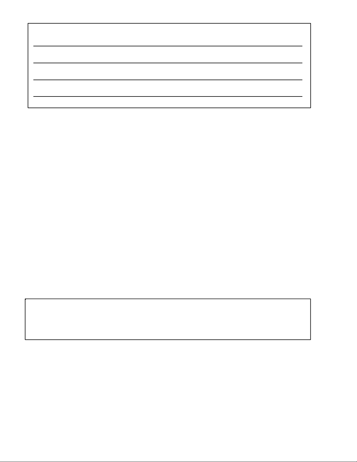
SF-1 DISPENSING VALVES
Valve No. Includes:
AND
Type of Flow
Rate
*(see Note)
318806015
318807015
Cover w/Water Lever
Cover w/o Water Lever
Standard-Flow
Standard-Flow
2103 Portion Control and Cover w/o Water Lever Fast-Flow
318813015
318812015
1690 Self-Serve Dispense Switch
Cover w/Water Lever
Cover w/o Water Lever
Fast-Flow
Fast-Flow
Standard-Flow
Cover w/o
Water Lever
WATER
FLOWASHER
ASS’Y
ADJUSTABLE
SYRUP
REGULATOR
PORTION
CONTROL
MODULE
ADJUSTABLE
SYRUP
REGULATOR
ADJUSTABLE
WATER
REGULATOR
ADJUSTABLE
WATER
REGULATOR
ADJUSTABLE
SYRUP
REGULATOR
SELF-SERVE
SWITCH
ADJUSTABLE
SYRUP
REGULATOR
ADJUSTABLE
WATER
REGULATOR
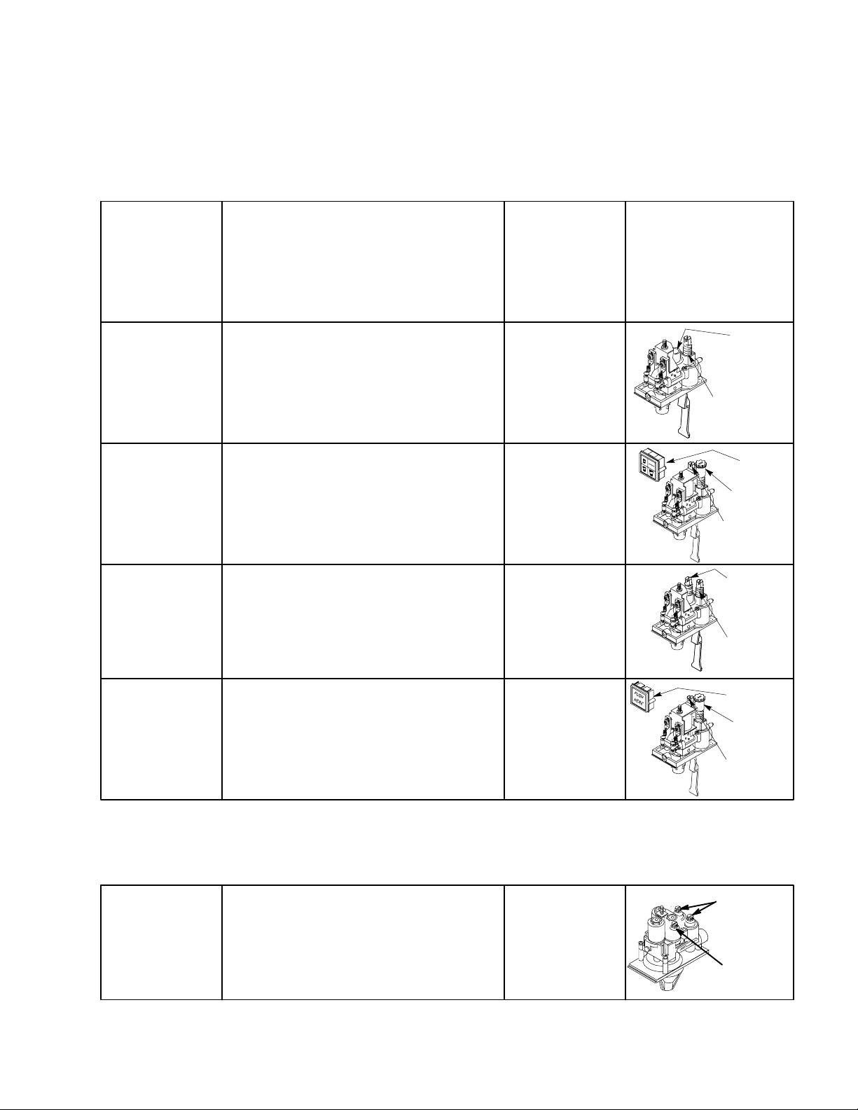
GEMINI DISPENSING VALVE (TWO-FLAVOR)
309912000 Standard Gemini Cover Fast-Flow
*NOTE FLOW RATE: 1. Fast-Flow Valves - Adjustable syrup and water regulators.
2. Standard-Flow - Adjustable syrup regulator and non-adjustable water flow.
ADJUSTABLE
SYRUP
REGULATOR
ADJUSTABLE
WATER
REGULATOR
3190060005
Page 9

THIS PAGE LEFT BLANK INTENTIONALLY
319006000 6
Page 10

ADJUSTMENTS
INTRODUCTION
This manual is intended to assist the Operator and Service Personnel in the Operation and Maintenance
procedures to be performed.
WATER FLOW RATE
Dispensing Valve With Water Flowasher.
Water flowasher is at a fixed water flow rate and is nonadjustable.
Dispensing Valve With Adjustable Water Flow Regulator.
Turn dispensing valve water flow regulator adjusting screw to the left (counterclockwise) no more than 1/4 turn
at a time for less water or to the right (clockwise) no more than 1/4 turn at a time for more water.
WATER-TO-SYRUP ‘‘RATIO’’ OF DISPENSED PRODUCT
SF-1 Single-Flavor Dispensing Valve.
(see Figure 1)
NOTE: Make sure water flow rate is satisfactory or has been adjusted on dispensing valve with
adjustable water flow regulator.
Adjust Water-to-Syrup ‘‘Ratio’’ of dispensed product by using Ratio Cup (P/N 311100000) and Syrup Diversion
Tube Assembly (P/N 319540-000) as follows (see Figure 1).
1. Remove acorn nut securing cover on dispensing valve, then remove cover from valve.
2. Install syrup diversion tube assembly on dispensing valve by pushing rubber end of syrup diversion tube up
on baffle inside nozzle.
NOTE: Refer to syrup manufacturer’s recommendations on syrup package for Water-to-Syrup ‘‘Ratio’’.
3. Open dispensing valve and dispense just enough to fill syrup diversion tube with syrup.
4. Hold large chamber of ratio cup under dispensing valve nozzle. Place free end of syrup diversion tube into
syrup chamber marked for proper ratio. Open dispensing valve and dispense approximately 5 ounces of
water into ratio cup. Water and syrup levels should be even in cup.
5. Adjusting Syrup Flow Regulator. If water and syrup levels are not even in ratio cup, turn dispensing valve
syrup flow regulator labeled ‘‘SYRUP’’ adjusting screw to the left (counterclockwise) no more than 1/4-turn
at a time for less syrup or to the right (clockwise) no more than 1/4-turn at a time for more syrup.
6. Repeat Water-to-Syrup ‘‘Ratio’’ test and adjust syrup flow regulator as many times as necessary until
proper ratio of dispensed drink is achieved.
7. Remove syrup diversion tube assembly from dispensing valve.
8. Install dispensing valve cover and secure with acorn nut.
3190060007
Page 11

Gemini Two-Flavor Dispensing Valve.
(see Figure 1)
NOTE: Make sure water flow rate is satisfactory or has been adjusted on dispensing valve with
adjustable water flow regulator before adjusting Water-to-Syrup ‘‘Ratio’’ of dispensed drinks.
Adjust Water-to-Syrup ‘‘Ratio’’ of dispensed product by using Ratio Cup (P/N 311100000) and Syrup Diversion
Tube Assembly (P/N 319540000) as follows (see Figure 1).
1. Remove acorn nut securing dispensing valve cover, then remove cover from valve.
2. Remove nozzle from dispensing valve.
3. Slide nozzle on to long portion of syrup diversion tube, then push rubber end of syrup diversion tube up on
dispensing valve syrup outlet.
4. Slide nozzle up on syrup diversion tube and reinstall on dispensing valve.
NOTE: Refer to syrup manufacturer’s recommendations on syrup package for Water-to-Syrup ‘‘Ratio’’.
5. Hold large chamber of ratio cup under dispensing valve nozzle. Place free end of syrup diversion tube into
syrup chamber marked for proper ratio. Press applicable dispense button and dispense approximately 5
ounces of water into ratio cup. Water and syrup levels should be even in ratio cup.
6. If water and syrup levels are not even in ratio cup, turn applicable syrup flow regulator adjusting screw to
the left (counterclockwise) no more than 1/4-turn at a time for less syrup or to the right (clockwise) no more
than 1/4-turn at a time for more syrup.
7. Repeat Water-to-Syrup ‘‘Ratio’’ test and adjust syrup flow regulator as many times as necessary until
proper ratio of dispensed drink is achieved.
8. Remove syrup diversion tube from dispensing valve syrup outlet and install on other syrup outlet.
9. Repeat preceding steps 5 through 7 to adjust Water-to-Syrup ‘‘Ratio’’ of dispensed drink to other
dispensing valve syrup system.
10. Remove nozzle and syrup diversion tube from dispensing valve.
11. Remove nozzle from syrup diversion tube, then install nozzle on dispensing valve.
12. Install dispensing valve cover and secure with acorn nut.
ADJUSTING SF-1 DISPENSING VALVE PORTION CONTROL FOR SIZE OF
DRINK DISPENSED
(see Figure 2)
NOTE: Drink size switches S (SMALL), M (MEDIUM), and L (LARGE) must be momentarily depressed,
then released before dispensing of drink will occur. Drinks may be manually dispensed by pressing
cup or glass against dispensing valve lever should portion control module become inoperative. The
CANCEL/POUR switch may be used for three separate dispensing functions as follows:
A. Portion control drink may be cancelled by momentarily depressing and releasing CANCEL/POUR
switch. DO NOT HOLD SWITCH IN DEPRESSED POSITION AS DRINK WILL NOT CANCEL AND
DISPENSING WILL CONTINUE.
B. CANCEL/POUR switch may also be used to dispense a non-portion controlled drink by merely
depressing and holding CANCEL/POUR switch until desired drink has been dispensed, then release
switch.
C. Press CANCEL/POUR switch to return to operational mode after all portion size adjustments have
been completed.
319006000 8
Page 12

1. Simultaneously pressing the small and large portion size buttons activates the set mode LED light which
will blink indicating the set mode is active.
2. Put desired amount of ice in correct portion size cup, place under dispensing valve nozzle. Press selected
size button (small, medium, or large) and hold until cup fills to desired portion, then release the button.
3. Repeat step 2 for remaining drink sizes.
4. After programming all drink sizes, press the CANCEL/POUR switch to cancel the programming cycle and
return the autoset portion control to the operational mode. The LED light turns off.
SF-1 SINGLE FLAVOR DISPENSING VALVE
WATER FLOW
REGULATOR
SYRUP FLOW
REGULATOR
*NOZZLE
WATER
CHAMBER
*Baffle (syrup distributor) may be removed by first removing
nozzle, then pull distributor down and off valve.
SYRUP DIVERSION
TUBE ASS’Y (P/N
319540000)
RATIO CUP (P/N
311100000)
FIGURE 1. RATIO CUP AND SYRUP DIVERSION TUBE ASSEMBLY
GEMINI TWO-FLAVOR DISPENSING VALVE
ADJUSTABLE WATER
FLOW REGULATOR
(IF APPLICABLE)
WATER
CHAMBER
ADJUSTABLE
SYRUP FLOW
REGULATOR (2)
SYRUP
OUTLET (2)
SYRUP DIVERSION
TUBE (P/N 319540000)
RATIO CUP
(P/N 311100000)
SMALL
MEDIUM
LED LIGHT
LARGE
FIGURE 2. PORTION CONTROL ADJUSTMENT
3190060009
Page 13

THIS PAGE LEFT BLANK INTENTIONALLY
319006000 10
Page 14

OPERATION
SF-1 DISPENSING VALVE
Standard SF-1 Electric Dispensing Valve.
1. Press cup or glass against dispensing valve lever and dispense product until cup or glass is full, then
release lever. If carbonated water only is desired, place cup or glass under dispensing valve with lever on
its side. Actuate lever and dispense until cup or glass is full of carbonated water, then release lever.
SF-1 Dispensing Valve With Self-Serve Dispense Switch.
1. Place cup or glass under dispensing valve nozzle.
2. Press dispense switch and dispense until cup or glass is full of product, then release switch.
SF-1 Dispensing Valve With Portion Control.
NOTE: Drink size switches S (SMALL), M (MEDIUM), and L (LARGE) must be momentarily depressed,
then released before dispensing of drink will occur. Drinks may be manually dispensed by pressing
cup or glass against dispensing valve lever should portion control module become inoperative. The
CANCEL/POUR switch may be used for two separate dispensing functions as follows:
A. Portion control drink may be cancelled by momentarily depressing and releasing the CANCEL/POUR
switch. DO NOT HOLD SWITCH IN DEPRESSED POSITION AS DRINK WILL NOT CANCEL AND
DISPENSING WILL CONTINUE.
B. CANCEL/POUR switch may also be used to dispense a non-portion controlled drink by merely
depressing and holding CANCEL/POUR switch until desired drink has been dispensed, then release
switch.
1. Place cup or glass under dispensing valve nozzle.
2. Momentarily depress and release S (SMALL), M (MEDIUM), or L (LARGE) drink size switch to dispense
portion size drink. Dispensing will stop at end of portion cycle.
GEMINI TWO-FLAVOR DISPENSING VALVE
1. Place cup or glass under dispensing valve nozzle.
2. Press and hold dispense button and dispense product until cup or glass is full, then release button.
1. Remove nozzle and baffle from dispensing valve. Wash nozzle and baffle in warm water, then install nozzle
and baffle on valve.
NOTE: Refer to REMOVAL AND REPLACEMENT PROCEDURES for applicable instructions should
syrup or water flow regulator, water flowasher assembly, need to be removed from dispensing valve
and cleaned.
31900600011
Page 15

THIS PAGE LEFT BLANK INTENTIONALLY
319006000 12
Page 16

SERVICE AND MAINTENANCE
REMOVAL AND REPLACEMENT PROCEDURES ON SF-1 VALVE
(see Figure 3)
REMOVE AND REPLACE SOLENOID COIL (item 12)
Removal.
1. Remove acorn nut securing dispensing valve cover, then remove cover from valve.
2. Disconnect electrical wiring from solenoid coil.
3. Remove two MACHINE SCREWS (item 11.) securing SOLENOID COIL (item 12.) to dispensing valve,
then remove coil from coil plunger.
Installation.
1. Install new solenoid coil by reversing removal procedure.
2. Install dispensing valve cover and secure with acorn nut.
REMOVE AND REPLACE MICRO SWITCH (item 13)
Removal.
1. Remove acorn nut securing dispensing valve cover, then remove cover from valve.
2. Tag electrical wires connected to MICRO SWITCH (item 13.) for identification, then disconnect wires from
switch terminals.
3. Remove MACHINE SCREW (item 14.) securing MICRO SWITCH (item 13.) to dispensing valve, then remove switch.
Installation.
1. Install new micro switch by reversing removal procedure.
2. Install dispensing valve cover and secure with acorn nut.
REMOVE AND REPLACE SYRUP OR WATER FLOW REGULATOR
Removal.
1. Remove acorn nut securing dispensing valve cover, then remove cover from valve.
2. Disconnect electric or portion control dispensing valve wiring harness connector from unit wiring harness
connector.
31900600013
Page 17

35.
36.
18.
17.
24.
19.
26.
27.
12.
21.
19.
22.
23.
28.
19.
24.
34.
29.
11.
10.
7.
8.
31.
4.
3.
6.
5.
ITEM
2.
1.
DESCRIPTION
NO.
1. Cover Ass’y (varies with dispensing valve model)
2. Acorn Nut, Nickel-pltd
3. Screw, Thread Cutting, No. 6-32 by 3/4-in. long
4. Bottom Cover
5. Nozzle
6. Baffle
7. Spring
8. Inlet Valve
9. Valve Block
10. Setscrew , Hex Socket, No. 8-32 by 1/2-in. long
11. Machine Screw, No. 10-32 by 3/8-in. long
12. Solenoid Coil
13. Micro Switch
14. Machine Screw, No. 2-56 by 7/16-in. long
15. Mounting Block Ass’y
16. Screw, Thread Rolling, No. 10-32 by 1-in. long
17. Plate
18. Screw, Thread Cutting, No. 8-32 by 5/16-in. long
19.
26.
30.
14.
13.
9.
27.
28.
19.
15.
16.
.125
32.
33.
ITEM
DESCRIPTION
NO.
19. O-Ring, .676 I.D. by .070 C.S.
20.
21. Housing, Water Flowasher
22. Flowasher
23. Retainer
24. T op Flow Control
25.
26. Spring
27. Piston
28. Cylinder
29. Portion Control Module
30. Body
31. Short Nib, Syrup
Long Nib, Water
32. O-Ring, .799 I.D. by .103 C.S.
33. O-Ring, .157 I.D. by .038 C.S.
34. Dispense Switch Module
35. Bracket, Cover, Manual
36. Hex Nut, No. 10-32
319006000
FIGURE 3. PARTS IDENTIFICATION (SF-1 DISPENSING VALVE)
14
Page 18

3. Pull dispensing valve release latch (see Figure 3), located on mounting block assembly back of valve, to
the left to release valve. Release safety latch on bottom of the valve block, then pull valve off block assembly.
4. Remove two SCREWS (item 18.) securing PLATE (item 17.) that secure flow regulator in dispensing valve
BODY (item 30.), then remove plate.
5. Pull TOP FLOW CONTROL (item 24.), SPRING (item 26.), and PISTON (item 27.) up out of flow regulator
CYLINDER (item 28.).
6. The CYLINDER (item 28.) normally does not need to be removed from BODY (item 30.). If the need to remove cylinder should arise, pull cylinder up out of body. ALWAYS INSTALL NEW O-RING (item 19.)
P/N 317816000 ON CYLINDER BEFORE INSTALLING CYLINDER IN BODY.
Installation.
1. Install TOP FLOW CONTROL (item 24.), SPRING (item 26.), and PISTON (item 27.) in CYLINDER (item
28.).
2. Secure water flow or syrup flow regulator in dispensing valve BODY (item 30.) with PLATE (item 17.) and
SCREWS (item 18.).
3. Install dispensing valve on unit by inserting valve guide pin in mounting block assembly guide pin hole.
Push valve on block until a click is heard indicating release latch has seated in valve guide pin notch.
MAKE SURE SAFETY LATCH ON BOTTOM OF DISPENSING VALVE IS HOOKED TO SECURE VALVE
ON BLOCK.
4. Connect dispensing valve wiring harness connector to unit wiring harness connector, then install valve cover.
5. Water Flow Regulator Removed.
If water flow regulator was removed from dispensing valve, water flow rate must be checked and if neces-
sary, regulator must be adjusted as instructed.
Syrup Flow Regulator Removed.
If syrup flow regulator was removed, check dispensing valve for Water-to-Syrup ‘‘Ratio’’ of dispensed product and if necessary, adjust as instructed.
6. Install dispensing valve cover and secure with acorn nut.
REMOVE AND REPLACE WATER FLOWASHER ASS’Y
Removal.
1. Remove acorn nut securing dispensing valve cover, then remove cover from valve.
2. Disconnect dispensing valve wiring harness connector from unit wiring harness connector.
3. Pull dispensing valve release latch (see Figure 3), located on mounting block assembly back of valve, to
the left to release valve block, release safety latch on bottom of the valve, then pull valve off block assembly.
4. Remove two SCREWS (item 18.) securing PLATE (item 17.) that secure water flowasher assembly in dispensing valve BODY (item 30.), then remove plate.
5. Pull water flowasher assembly up out of dispensing valve BODY (item 30.).
6. Remove water flowasher RETAINER (item 23.) from bottom of HOUSING, WATER FLOWASHER (item
21.), then remove FLOWASHER (item 22.) from housing.
15
319006000
Page 19

Installation.
1. Install FLOWASHER (item 22.) in bottom of HOUSING, WATER FLOWASHER (item 21.) and secure with
RETAINER (item 23.). FLOWASHER MUST BE INSTALLED IN WATER FLOWASHER HOUSING WITH
CONCAVE SURFACE OF FLOWASHER FACING AWAY FROM ITS RETAINER.
IMPORTANT: New O-RINGS (item 19.) P/N 317816000 must be installed on water flowasher assembly
before its installation in dispensing valve body.
2. Install water flowasher assembly in dispensing valve body.
3. Secure flowasher assembly in dispensing valve body with PLATE (item 17.) and SCREWS (item 18.).
4. Install dispensing valve on unit by inserting valve guide pin in mounting block assembly guide pin hole.
Push valve on block until a click is heard indicating release latch has seated in valve guide pin notch.
MAKE SURE SAFETY LATCH ON BOTTOM OF DISPENSING VALVE IS LOCKED TO SECURE VALVE
ON BLOCK.
5. Connect dispensing valve electrical wiring harness connector to unit wiring harness connector.
6. Install dispensing valve cover and secure with acorn nut.
REMOVE AND REPLACE INLET VALVE
Removal.
1. Remove acorn nut securing dispensing valve cover, then remove cover from valve.
2. Disconnect dispensing valve wiring harness connector from unit wiring harness connector.
3. Pull dispensing valve release latch (see Figure 3), located on mounting block assembly back of valve, to
the left to release valve. Release safety latch on bottom of the valve block, then pull valve off block assembly.
4. Turn dispensing valve upside down, then disconnect SPRINGS (item 7.) from INLET VALVES (item 8.).
5. Remove four SCREWS (item 3.) securing dispensing valve BOTTOM COVER (item 4.) and VALVE
BLOCK (item 9.) to BODY (item 30.), then separate valve block from body.
6. Remove inlet valve from valve block.
7. Remove NIB (item 31.) from inlet valve.
NOTE: Short nib is for syrup inlet valve and long nib is for water inlet valve.
Installation.
1. Install inlet valve and assemble dispensing valve by reversing disassembly procedure.
2. Install dispensing valve on unit by inserting valve guide pin in mounting block assembly guide pin hole.
Push valve on block until a click is heard indicating release latch has seated in valve guide pin notch.
MAKE SURE SAFETY LATCH ON BOTTOM OF DISPENSING VALVE IS HOOKED TO SECURE VALVE
ON BLOCK.
NOTE: It may be necessary to adjust inlet valves so water and syrup dispensing start at same time and
stop at same time by turning SETSCREWS (item 10.).
3. Connect dispensing valve wiring harness connector to unit wiring harness connector.
319006-000
16
Page 20

4. Install dispensing valve cover and secure with acorn nut.
REMOVE AND REPLACE PORTION CONTROL MODULE
Removal.
1. Remove screw securing dispensing valve cover, then remove cover from valve.
2. Tag electrical wires for identification, then disconnect PORTION CONTROL MODULE (item 29.) wires from
solenoid coil and unit wiring harness connector.
3. Lift portion control module up out of holding brackets on dispensing valve.
Installation.
1. Install portion control module by reversing removal procedure.
2. Adjust portion control module for size of drinks dispensed as instructed.
3. Install dispensing valve cover and secure with acorn nut.
REMOVE AND REPLACE SELF-SERVE DISPENSE SWITCH MODULE
Removal.
1. Remove acorn nut securing dispensing valve cover, then remove cover from valve.
2. Lift DISPENSE SWITCH MODULE (item 34.) up out of holding brackets on dispensing valve.
3. Disconnect dispense switch module electrical connector from dispenser wiring harness connector.
4. Disconnect dispense switch module electrical wires from dispensing valve solenoid coil terminals.
Installation
1. Install dispense switch module by reversing removal procedure.
REMOVAL AND REPLACEMENT PROCEDURE ON GEMINI TWO-FLAVOR
DISPENSING VAL VE
(see Figure 4)
REMOVE AND REPLACE SYRUP OR WATER SOLENOID AND COIL ASS’Y
Removal.
1. Remove acorn nut securing dispensing valve cover, then remove cover from valve.
17
319006000
Page 21

3
9
3
4
5
6
7
21
22
23
2
1
24
25
20
10
11
12
13
14
15
17
16
8
SAFTEY
LATCH
19
18
RELEASE
LATCH
28
29
30
ITEM
DESCRIPTION
NO.
1 Cover Ass’y (includes switches and circuit board
assembly)
2 Acorn Nut, Nickel-pltd, No. 10-32
3 O-Ring, .551 I.D. by .070 C.S.
4 Housing, Flowasher
5 Flowasher, 60 GPM
6 Flowasher Cap
7 O-Ring, .426 I.D. by .070 C.S.
8 O-Ring, .488 I.D. by .040 C.S.
9 Top Flow Control
10 Screw, Adjusting Spring
11 O-Ring, .208 I.D. by .070 C.S.
12 Spring, Flow Regulator
13 Piston
14 Cylinder
15 Cover Mounting Bracket
27
26
ITEM
DESCRIPTION
NO.
16 Retainer Plate
17 Thread Rolling Screw, Phil Pan Hd, No. 8-16 by
7/16-in. long
18 Mounting Block Ass’y
19 Backup Plate
20 Solenoid and Coil Ass’y (Water or Syrup)
21 O-Ring, .426 I.D. by .070 C.S.
22 Thread Rolling Screw, Phil Pan Hd, Nickel-pltd,
No. 6-32 by 3/4-in. long
23 Valve Body
24 O-Ring, .239 I.D. by .070 C.S.
25 Valve Bottom
26 O-Ring, .239 I.D. by .070 C.S.
27 Thread Rolling Screw, Phil Pan Hd, Stainless
Steel, No. 6-19 by 3/8-in. long
28 Baffle
29 O-Ring, 1.549 I.D. by .103 C.S.
30 Nozzle
319006000
FIGURE 4. PARTS IDENTIFICATION (GEMINI TWO-FLAVOR DISPENSING VALVE)
18
Page 22

2. Disconnect dispensing valve wiring harness connector from dispenser wiring harness connector.
3. Disengage safety latch on bottom of dispensing valve (see Figure 4) from pin on bottom of mounting block
assembly.
4. Push down on dispensing valve release latch located on top of mounting block assembly (see Figure 4) to
release valve from block assembly, then pull valve off block.
5. Remove COVER MOUNTING BRACKET (item 15) from dispensing valve.
6. Cut two electrical wires connected to inoperable SOLENOID AND COIL ASS’Y (item 20).
7. Remove inoperable SOLENOID AND COIL ASS’Y (item 20) from VALVE BODY (item 23) by turning solenoid and coil assembly to the left (counterclockwise).
8. Remove old O-RING (item 21) from VALVE BODY (item 23) bore where solenoid and coil assembly was
removed.
Installation.
1. Install new O-RING (item 21) in VALVE BODY (item 23) bore.
2. Install new SOLENOID AND COIL ASS’Y (item 20) by reversing removal procedure.
3. Connect new solenoid and coil assembly electrical wires to dispensing valve wiring harness. Secure connections with wire nuts (not provided).
4. Install dispensing valve on unit by inserting valve guide pin in mounting block assembly guide pin hole.
Push valve on block until a click is heard indicating release latch has seated in valve guide pin notch.
MAKE SURE SAFETY LATCH ON BOTTOM OF DISPENSING VALVE IS HOOKED ON MOUNTING
BLOCK PIN TO SECURE VALVE ON BLOCK.
5. Connect dispensing valve wiring harness connector to dispenser wiring harness connector.
6. Install dispensing valve cover and secure with acorn nut.
REMOVE AND REPLACE SYRUP OR WATER FLOW REGULATOR
Removal.
1. Remove acorn nut securing dispensing valve cover, then remove cover from valve.
2. Disconnect dispensing valve wiring harness connector from dispenser wiring harness connector.
3. Disengage safety latch on bottom of dispensing valve (see Figure 4) from pin on bottom of mounting block
assembly.
4. Push down on dispensing valve release latch on top of mounting block assembly (see Figure 4) to release
valve from block assembly, then pull valve off block.
5. Remove three THREAD ROLLING SCREWS (item 17) securing RETAINER PLATE (item 16) that secures
flow regulator in VALVE BODY (item 23), then remove plate.
6. Pull TOP FLOW CONTROL (item 9), SPRING (item 12), and PISTON (item 13) up out of flow regulator
CYLINDER (item 14).
7. The CYLINDER (item 14) normally does not need to be removed from VALVE BODY (item 23). If the need
to remove cylinder should arise, pull cylinder up out of valve body. ALWAYS INSTALL NEW O-RING
(item 8) P/N 309650000 on cylinder before installing cylinder in valve body.
19319006000
Page 23

Installation.
1. Install TOP FLOW CONTROL (item 9), SPRING (item 12) and PISTON (item 13) in CYLINDER (item 14).
2. Secure flow regulator in VALVE BODY (item 23) with RETAINER PLATE (item 16) and THREAD ROLLING
SCREWS (item 11).
3. Install dispensing valve on unit by inserting valve guide pin in mounting block assembly guide pin hole.
Push valve on block until a click is heard indicating release latch has seated in valve guide pin notch.
MAKE SURE SAFETY LATCH ON BOTTOM OF DISPENSING VALVE IS HOOKED ON MOUNTING
BLOCK PIN TO SECURE VALVE ON BLOCK.
4. Connect dispensing valve wiring harness connector to dispenser wiring harness connector.
5. Water Flow Regulator Removed.
If water flow regulator was removed, dispensing valve water flow rate must be checked and if necessary,
regulator must be adjusted as instructed.
Syrup Flow Regulator Removed.
If syrup flow regulator was removed, check dispensing valve for Water-to-Syrup ‘‘Ratio’’ of dispensed product and if necessary, adjust as instructed.
6. Install dispensing valve cover and secure with acorn nut.
REMOVE AND REPLACE WATER FLOWASHER ASS’Y
Removal.
1. Remove acorn nut securing dispensing valve cover, then remove cover from valve.
2. Disconnect dispensing valve wiring harness connector from dispenser wiring harness connector.
3. Disengage safety latch on bottom of dispensing valve (see Figure 4) from pin on bottom of mounting block
assembly.
4. Push down on dispensing valve release latch on top of mounting block assembly (see Figure 4) to release
valve from block assembly, then pull valve off block.
5. Remove three THREAD ROLLING SCREWS (item 17) securing RETAINER PLATE (item 16) that secures
water flowasher assembly in VALVE BODY (item 23), then remove plate.
6. Pull water flowasher assembly up out of VALVE BODY (item 23).
7. Remove water flowasher FLOWASHER CAP (item ) from bottom of HOUSING, FLOWASHER (item 4),
then remove FLOWASHER (item 5) from housing.
Installation.
1. Install FLOWASHER (item 5) in bottom of HOUSING, FLOWASHER (item 4) and secure with FLOWASHER CAP (item 6). FLOWASHER MUST BE INSTALLED IN WATER FLOWASHER HOUSING WITH CONCAVE SURFACE OF FLOWASHER FACING AWAY FROM ITS RETAINER.
IMPORTANT: New O-RING (item 3) P/N 150160000 and O-RING (item 7) P/N 187436000 must be installed
when installing water flowasher assembly in valve body.
2. Install water flowasher assembly in dispensing valve body.
20319006000
Page 24

3. Secure water flowasher assembly in dispensing valve body with RETAINER PLATE (item 16) and THREAD
ROLLING SCREWS (item 17).
4. Install dispensing valve on unit by inserting valve guide pin in mounting block assembly guide pin hole.
Push valve on block until a click is heard indicating release latch has seated in valve guide pin notch.
MAKE SURE LATCH ON BOTTOM OF DISPENSING VALVE IS HOOKED ON MOUNTING BLOCK PIN
TO SECURE VALVE ON BLOCK.
5. Connect dispensing valve wiring harness connector to dispenser wiring harness connector.
6. Install dispensing valve cover and secure with acorn nut.
REMOVE AND REPLACE DISPENSING VALVE COVER ASS’Y (INCLUDES CIRCUIT
BOARD AND DISPENSING SWITCHES)
Removal.
1. Remove acorn nut securing dispensing valve cover, then remove cover from valve.
2. Disconnect dispensing valve wiring harness connector from circuit board connector inside cover.
Installation.
1. Connect dispensing valve wiring harness connector to circuit board connector inside COVER ASS’Y
(item 1).
2. Install dispensing valve cover and secure with acorn nut.
21319006000
Page 25

FRONT
SOLENOID
TOP VIEW
WHITE
CONNECTOR
1
2
portion control
FIGURE 5. WIRING DIAGRAM (SF-1 PORTION CONTROL DISPENSING VALVE)
WHITE
RED
BLACK
FRONT
BLACK
SWITCH
SOLENOID
TOP VIEW
BLACK
C
SWITCH
C
N.O.
N.C.
1
2
N.O.
N.C.
RIGHT SIDE VIEW
FIGURE 6. WIRING DIAGRAM (SF-1 STANDARD ELECTRIC DISPENSING VALVE)
22319006000
Page 26

SOLENOID
COIL
TWO-SOCKET
CONNECTOR
BLACK
WHITEWHITE
DISPENSER WIRING
HARNESS
RED
PUSH
HERE
SELF SER VE
DISPENSE
SWITCH
wWHITE
BLACK
TWO-PIN
CONNECTOR
FIGURE 7. WIRING DIAGRAM (SF-1 DISPENSING VALVE WITH SELF-SERVE DISPENSE SWITCH)
6 5 4 3 2 1
MEMBRANE SWITCH
CONTROL MODULE
4 3 2 1
FIGURE 8. WIRING DIAGRAM (GEMINI TWO-FLAVOR DISPENSING VALVE)
SOL-2
SOL-3
12
POWER-IN CONNECTOR
SOL-1
23319006000
Page 27

THIS PAGE LEFT BLANK INTENTIONALLY
319006000 24
Page 28

TROUBLESHOOTING
IMPORTANT: Only qualified personnel should service internal components or electrical wiring.
WARNING: If repairs are to be made to a product system, remove quick disconnects from
the applicable product tank, then relieve the system pressure before proceeding. If repairs
are to be made to the CO
system, stop dispensing, shut off the CO
2
system pressure before proceeding. If repairs are to be made to the refrigeration system, make sure
electrical power is disconnected from the unit.
Trouble Probable Cause Remedy
supply, then relieve the
2
WATER-TO-SYRUP ‘‘RATIO’’
TOO LOW OR TOO HIGH.
ADJUSTMENT OF
DISPENSING VALVE SYRUP
FLOW REGULATOR DOES
NOT INCREASE TO DESIRED
WATER-TO-SYRUP ‘‘RATIO’’.
A. Dispensing valve syrup flow
regulator not properly
A. Adjust Water-to-Syrup ‘‘Ratio’’ as
instructed.
adjusted.
B. CO2 gas pressure to syrup
tanks insufficient to push syrup
B. Adjust syrup tanks secondary
CO2 regulator.
out of tanks.
A. No syrup supply. A. Replenish syrup supply.
B. Syrup tank quick disconnect
not securely connected to
B. Securely connect quick
disconnect to tank.
tank.
C. Syrup tanks CO2 regulator out
C. Adjust syrup tanks CO
of adjustment.
D. Dispensing valve syrup flow
D. Sanitize syrup system.
regulator, syrup tank quick
disconnect, or syrup line
restricted.
E. Improper syrup Baume. E. Replace syrup supply.
F. Dirty or inoperative piston or
spring in dispensing valve
adjustable syrup flow
F. Disassemble and clean
dispensing valve syrup flow
regulator.
regulator.
regulator.
2
ADJUSTMENT OF
DISPENSING VALVE SYRUP
FLOW REGULATOR DOES
NOT DECREASE TO
DESIRED WATER-TO-SYRUP
‘‘RATIO’’.
NO PRODUCT DISPENSED
FROM ALL DISPENSING
VALVES.
G. Tapered nylon washer inside
tube swivel nut connector (if
applicable) distorted from
being overtightened.
A. Dirty or inoperative piston or
spring in dispensing valve
adjustable syrup flow
regulator.
A. No electrical power to
dispenser.
B. Disconnected or broken wiring
to dispensing valves.
25 319006000
G. Replace nylon washer and make
sure it seats properly.
A. Disassemble and clean
dispensing valve syrup flow
regulator.
A. Connect electrical power to
dispenser.
B. Connect or replace wiring.
Page 29

Trouble RemedyProbable Cause
NO PRODUCT DISPENSED
FROM ONE DISPENSING
VALVE.
ONLY CARBONATED WATER
DISPENSED.
C. Inoperative 115VAC
C. Replace transformer.
transformer.
A. Broken or disconnected wiring. A. Repair or connect wiring.
B. Inoperative dispensing valve
solenoid coil.
C. Inoperative dispensing valve
micro switch (SF-1 dispensing
B. Replace solenoid coil as
instructed.
C. Replace micro switch as
instructed.
valve only).
A. Quick disconnects not secure
on syrup tanks.
A. Secure quick disconnects on
syrup tanks.
B. Out of syrup. B. Replenish syrup supply as
instructed.
C. Syrup tanks CO2 regulator not
C. Adjust syrup tanks CO2 regulator.
properly adjusted.
D. Inoperable dispensing valve. D. Repair dispensing valve.
E. Dispensing valve adjustable
syrup flow regulator not
E. Adjust Water-to-Syrup ‘‘Ratio’’ as
instructed.
properly adjusted.
F. Dispensing valve adjustable
F. Sanitize syrup system.
syrup flow regulator, syrup
tank quick disconnect, or syrup
lines restricted.
ONLY SYRUP DISPENSED. A. No carbonated water supply. A. Restore carbonated water supply.
B. Dispensing valve adjustable
water flow regulator not
B. Adjust dispensing valve water
flow rate as instructed.
properly adjusted.
319006000 26
Page 30

WARRANTY
IMI Cornelius Inc. warrants that all equipment and parts are free from defects in material and workmanship under normal use and service. For a copy of the warranty applicable to your Cornelius, Remcor or Wilshire product, in your country, please write, fax or telephone the IMI Cornelius office nearest you. Please provide the
equipment model number, serial number and the date of purchase.
IMI Cornelius Offices
AUSTRALIA D P.O. 210, D RIVERWOOD, D NSW 2210, AUSTRALIA D (61) 2 533 3122 D FAX (61) 2 534 2166
D AM LANGEN FELDE 32 D A-1222 D VIENNA, AUSTRIA D (43) 1 233 520 D FAX (43) 1-2335-2930
AUSTRIA
D BOSKAPELLEI 122 D B-2930 BRAASCHAAT, BELGIUM D (32) 3 664 0552 D FAX (32) 3 665 2307
BELGIUM
D RUA ITAOCARA 97 D TOMAS COELHO D RIO DE JANEIRO, BRAZIL D (55) 21 591 7150 D FAX (55) 21 593 1829
BRAZIL
ENGLAND
D TYTHING ROAD ALCESTER D WARWICKSHIRE, B49 6 EU, ENGLAND D (44) 789 763 101 D FAX (44) 789 763 644
D 71 ROUTE DE ST. DENIS D F-95170 DEUIL LA BARRE D PARIS, FRANCE D (33) 1 34 28 6200 D FAX (33) 1 34 28 6201
FRANCE
GERMANY
GREECE
HONG
ITALY
NEW
SINGAPORE
SPAIN
USA
D CARL LEVERKUS STRASSE 15 D D-4018 LANGENFELD, GERMANY D (49) 2173 7930 D FAX (49) 2173 77 438
D 488 MESSOGION AVENUE D AGIA PAR AS KEVI D 153 42 D ATHENS, GREECE D (30) 1 600 1073 D FAX (30) 1 601 2491
KONG D 1104 TAIKOTSUI CENTRE D 11-15 KOK CHEUNG ST D TAIKOKTSUE, HONG KONG D (852) 789 9882 D FAX (852) 391 6222
D VIA PELLIZZARI 11 D 1-20059 D VIMARCATE, ITALY D (39) 39 608 0817 D FAX (39) 39 608 0814
ZEALAND D 20 LANSFORD CRES. D P.O . BOX 19-044 AVONDALE D AUCKLAND 7, NEW ZEALAND D (64) 9 8200 357 D FAX (64) 9 8200 361
D 16 TUAS STREET D SINGAPORE 2263 D (65) 862 5542 D FAX (65) 862 5604
D POLIGONO INDUSTRAIL D RIERA DEL FONOLLAR D E-08830 SANT BOI DE LLOBREGAT D BARCELONA, SPAIN D (34) 3 640 2839 D FAX (34) 3 654 3379
D ONE CORNELIUS PLACE D ANOKA, MINNESOTA D (612) 421-6120 D FAX (612) 422-3255
LD004
4/21/98
31900600027
Page 31

Page 32

IMI CORNELIUS INC.
CORPORATE HEADQUARTERS:
One Cornelius Place
Anoka, Minnesota 55303-6234
(612) 421-6120
(800) 238-3600
 Loading...