

Page 1
IMI CORNELIUS INC g One Cornelius Place g Anoka, MN 55303-6234
Telephone (800) 238-3600 Facsimile (763) 422-3246
Installation Manual
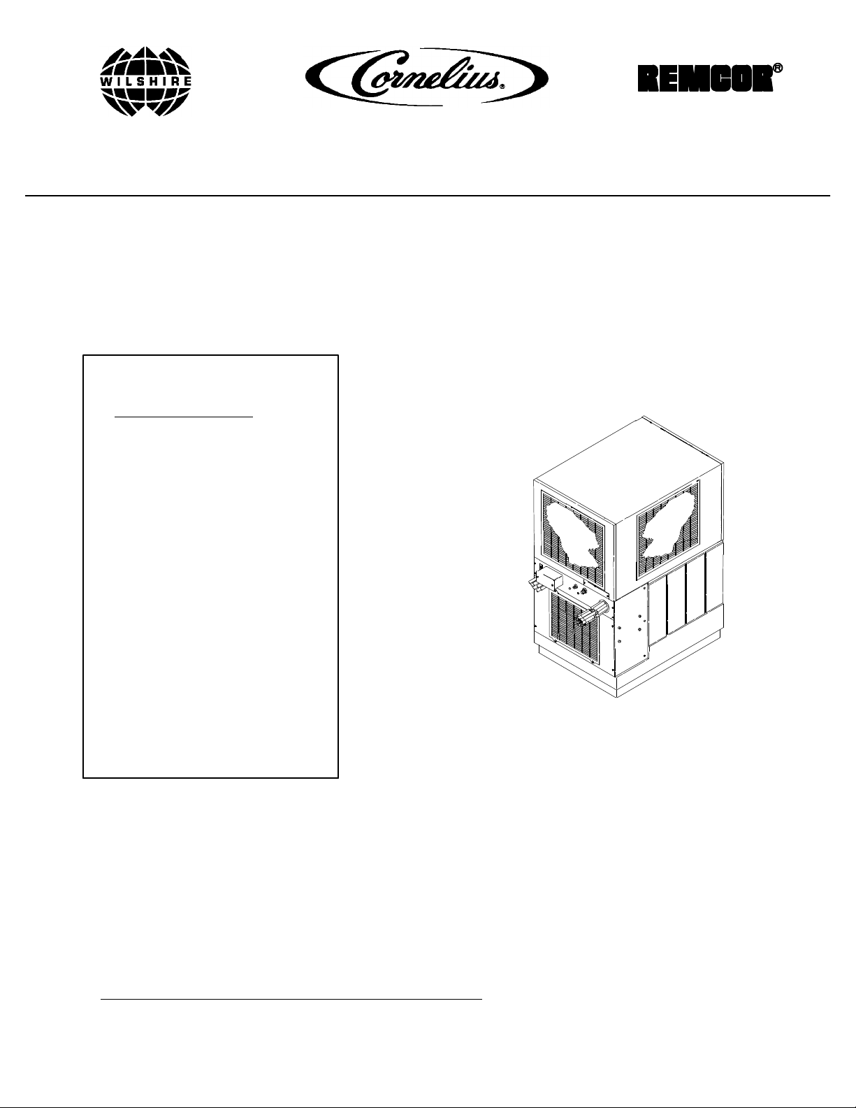
SENTRY III-A POST-MIX COOLING UNIT
(R-134A Refrigerant)
IMPORTANT:
TO THE INSTALLER.
It is the responsibility of
the Installer to ensure that
the water supply to the
dispensing equipment is
provided with protection
against backflow by an air
gap as defined in
ANSI/ASME A112.1.2-1979;
or an approved vacuum
breaker or other such
method as proved effective
by test.
Water pipe connections
and fixtures directly
connected to a potable
water supply shall be
sized, installed, and
maintained according to
Federal, State, and Local
Codes.
Part No. 312021001
December 16, 1994
Revised: December 1, 1995
Control Code A
THIS DOCUMENT CONTAINS IMPORTANT INFORMATION
This Manual must be read and understood before installing or operating this equipment
IMI CORNELIUS INC; 1994--95Ó
PRINTED IN U.S.A
Page 2

TABLE OF CONTENTS
SAFETY INFORMATION 1. . . . . . . . . . . . . . . . . . . . . . . . . . . . . . . . . . . . . . . . . . . . . . . . . . . .
RECOGNIZE SAFETY INFORMATION 1. . . . . . . . . . . . . . . . . . . . . . . . . . . . . . .
UNDERSTAND SIGNAL WORDS 1. . . . . . . . . . . . . . . . . . . . . . . . . . . . . . . . . . . .
FOLLOW SAFETY INSTRUCTIONS 1. . . . . . . . . . . . . . . . . . . . . . . . . . . . . . . . .
CO2 (CARBON DIOXIDE) WARNING 1. . . . . . . . . . . . . . . . . . . . . . . . . . . . . . . .
SHIPPING, STORING, OR RELOCATING UNIT 1. . . . . . . . . . . . . . . . . . . . . . .
GENERAL INFORMATION 3. . . . . . . . . . . . . . . . . . . . . . . . . . . . . . . . . . . . . . . . . . . . . . . . . .
CLAIMS INSTRUCTIONS 3. . . . . . . . . . . . . . . . . . . . . . . . . . . . . . . . . . . . . . . . . . . . . . .
WARRANTY REFERENCE INFORMATION 3. . . . . . . . . . . . . . . . . . . . . . . . . . . . . . .
DESIGN DATA 3. . . . . . . . . . . . . . . . . . . . . . . . . . . . . . . . . . . . . . . . . . . . . . . . . . . . . . . .
DESCRIPTION 4. . . . . . . . . . . . . . . . . . . . . . . . . . . . . . . . . . . . . . . . . . . . . . . . . . . . . . . .
THEORY OF OPERATION 5. . . . . . . . . . . . . . . . . . . . . . . . . . . . . . . . . . . . . . . . . . . . . .
PARTS IDENTIFICATION 7. . . . . . . . . . . . . . . . . . . . . . . . . . . . . . . . . . . . . . . . . . . . . . . . . . .
INSTALLA TION 9. . . . . . . . . . . . . . . . . . . . . . . . . . . . . . . . . . . . . . . . . . . . . . . . . . . . . . . . . . . .
UNPACKING AND INSPECTION 9. . . . . . . . . . . . . . . . . . . . . . . . . . . . . . . . . . . . . . . .
SELECTING LOCATION 9. . . . . . . . . . . . . . . . . . . . . . . . . . . . . . . . . . . . . . . . . . . . . . . .
INSTALLATION 9. . . . . . . . . . . . . . . . . . . . . . . . . . . . . . . . . . . . . . . . . . . . . . . . . . . . . . . .
PLACING COOLING UNIT IN OPERATING LOCATION 10. . . . . . . . . . . . . . . .
CONNECTING ELECTRICAL POWER TO COOLING UNIT 10. . . . . . . . . . . . .
FILL UNIT WATER TANK AND START REFRIGERATION SYSTEM 10. . . . .
CONNECTING PLAIN WATER SOURCE TO UNIT 11. . . . . . . . . . . . . . . . . . . .
CONNECTING CO2 SOURCE LINE TO UNIT 11. . . . . . . . . . . . . . . . . . . . . .
CONNECTING SYRUP SOURCE LINES TO UNIT AT THIS TIME 11. . . . . . .
CONNECTING INSULATED TRUNK PYTHON TO UNIT 11. . . . . . . . . . . . . . .
PREPARATION FOR OPERATION 11. . . . . . . . . . . . . . . . . . . . . . . . . . . . . . . . . . . . . . .
ADJUSTING CO2 REGULATORS 12. . . . . . . . . . . . . . . . . . . . . . . . . . . . . . . . . . .
ACTIVATING PLAIN WATER SOURCE AND STARTING CARBONATOR 12.
STARTING CARBONATED WATER CIRCULATING PUMP 12. . . . . . . . . . . . .
ACTIVATING SYRUP SYSTEMS 13. . . . . . . . . . . . . . . . . . . . . . . . . . . . . . . . . . . .
INSULATING PYTHON CONNECTION TO COOLING UNIT 13. . . . . . . . . . . . . . . . .
INSTALLING LINE IDENTIFICATION LABEL 13. . . . . . . . . . . . . . . . . . . . . . . . . . . . . .
TROUBLESHOOTING 15. . . . . . . . . . . . . . . . . . . . . . . . . . . . . . . . . . . . . . . . . . . . . . . . . . . . . .
Page
DISPENSED PRODUCT CARBONATION TOO LOW. 15. . . . . . . . . . . . . . . . . . . . . .
ONLY SYRUP DISPENSED. 15. . . . . . . . . . . . . . . . . . . . . . . . . . . . . . . . . . . . . . . . . . . .
WARM PRODUCT BEING DISPENSED 15. . . . . . . . . . . . . . . . . . . . . . . . . . . . . . . . . .
WATER PUMP WILL NOT OPERATE 15. . . . . . . . . . . . . . . . . . . . . . . . . . . . . . . . . . . .
WATER PUMP MOTOR WILL NOT SHUT OFF. 16. . . . . . . . . . . . . . . . . . . . . . . . . . .
ERRATIC CYCLING OF CARBONATOR. 16. . . . . . . . . . . . . . . . . . . . . . . . . . . . . . . . .
WATER PUMP MOTOR OPERATES BUT WATER PUMP DOES NOT PUMP
WATER. 16. . . . . . . . . . . . . . . . . . . . . . . . . . . . . . . . . . . . . . . . . . . . . . . . . . . . . . . . . . . . . .
WATER PUMP CAPACITY TOO LOW. 16. . . . . . . . . . . . . . . . . . . . . . . . . . . . . . . . . . .
COMPRESSOR DOES NOT OPERATE. 17. . . . . . . . . . . . . . . . . . . . . . . . . . . . . . . . . .
COMPRESSOR WILL NOT STOP AFTER SUFFICIENT ICE BANK IS
PRODUCED 17. . . . . . . . . . . . . . . . . . . . . . . . . . . . . . . . . . . . . . . . . . . . . . . . . . . . . . . . . .
i
312021001
Page 3

TABLE OF CONTENTS (cont’d)
COMPRESSOR OPERATES CONTINUOUSLY BUT DOES NOT FORM
SUFFICIENT ICE BANK. 18. . . . . . . . . . . . . . . . . . . . . . . . . . . . . . . . . . . . . . . . . . . . . . .
CONDENSER FAN MOTOR NOT OPERATING. 18. . . . . . . . . . . . . . . . . . . . . . . . . . .
AGITATOR MOTOR NOT OPERATING. 18. . . . . . . . . . . . . . . . . . . . . . . . . . . . . . . . . .
WARRANTY 19. . . . . . . . . . . . . . . . . . . . . . . . . . . . . . . . . . . . . . . . . . . . . . . . . . . . . . . . . . . . . .
LIST OF FIGURES
FIGURE 1. SENTRY III-A COOLING UNIT 4.. . . . . . . . . . . . . . . . . . . . . . . . . . . . . . .
FIGURE 2. SYSTEM FLOW DIAGRAM 6. . . . . . . . . . . . . . . . . . . . . . . . . . . . . . . . . . .
FIGURE 3. PARTS IDENTIFICATION 7. . . . . . . . . . . . . . . . . . . . . . . . . . . . . . . . . . . .
FIGURE 4. WIRING DIAGRAM (DROP-IN REFRIGERATION ASS’Y) 14. . . . . . . .
FIGURE 5. WIRING DIAGRAM (LOWER COOLING UNIT CABINET) 14. . . . . . . .
LIST OF TABLES
TABLE 1. DESIGN DATA 3. . . . . . . . . . . . . . . . . . . . . . . . . . . . . . . . . . . . . . . . . . . . . . .
TABLE 2. LOOSE-SHIPPED PARTS 9. . . . . . . . . . . . . . . . . . . . . . . . . . . . . . . . . . . . .
Page
312021001
ii
Page 4
SAFETY INFORMATION
Recognize Safety Information
This is the safety-alert symbol. When you see this
symbol on our machine or in this manual, be alert to
the possibility of personal injury.
Follow recommended precautions and safe operating
practices.
Understand Signal Words
A signal word - DANGER, WARNING, OR CAUTION
is used with the safety-alert symbol. DANGER identifies the most serious hazards.
DANGER
Safety signs with signal word DANGER or WARNING
are typically near specific hazards.
General precautions are listed on CAUTION safety
signs. CAUTION also calls attention to safety messages in this manual.
WARNING
CAUTION
Follow Safety Instructions
Carefully read all safety messages in this manual and on your machine safety signs. Keep safety signs in
good condition. Replace missing or damaged safety signs. Learn how to operate the machine and how to
use the controls properly . Do not let anyone operate the machine without instructions. Keep your machine in
proper working condition. Unauthorized modifications to the machine may impair function, safety, and affect
the machine life and may void the factory warranty.
CO2(Carbon Dioxide) Warning
CO2Displaces Oxygen. Strict Attention must be observed in the prevention of CO2(carbon dioxide)
gas leaks in the entire CO2and soft drink system. If a CO2gas leak is suspected, particularly in a
small area, immediately ventilate the contaminated area before attempting to repair the leak. Personnel exposed to high concentration of CO2gas will experience tremors which are followed rapidly by
loss of consciousness and suffocation.
Shipping, Storing, Or Relocating Unit
CAUTION: All water must be purged from the Unit if exposed to freezing temperature. A freezing ambient temperature will cause residual water remaining inside the Unit to freeze resulting in damage to
internal components of the Unit.
1 312021001
Page 5

THIS PAGE LEFT BLANK INTENTIONALLY
312021001 2
Page 6
GENERAL INFORMATION
CLAIMS INSTRUCTIONS
Claims: In the event of shortage, notify the carrier as well as IMI Cornelius Inc. immediately . In the event of
damage, notify the carrier. IMI Cornelius Inc. is not responsible for damage, occurring in transit, but will
gladly render assistance necessary to pursue your claim. Merchandise must be inspected for concealed
damage within 15 days of receipt.
WARRANTY REFERENCE INFORMATION
Warranty Registration Date
(to be filled out by customer)
Unit Part Number:
Serial Number:
Install Date:
Local Authorized
Service Center:
DESIGN DATA
Table 1. Design Data
Unit Part Numbers:
Domestic Unit 4164920000
Export Unit 4964920000
COOLING UNIT DATA
Cooling Unit Overall Dimensions: (with hood in place)
Height 36--1/4 inches
Width 19 inches
Depth 27 inches
NOTE: Cooling unit Stand P/N 309802069 (optional) with cooling unit in place on stand dimensions:
Height (approx) 74--1/4 inches
Width 36 inches
Depth 19--1/2 inches
Weights: (approximate)
Shipping Weight 260 pounds
Weight (W/O Cartoning) 240 pounds
Capacities:
Cooling Unit Water Bath (no ice bank) 16.8 gallons
3120210013
Page 7
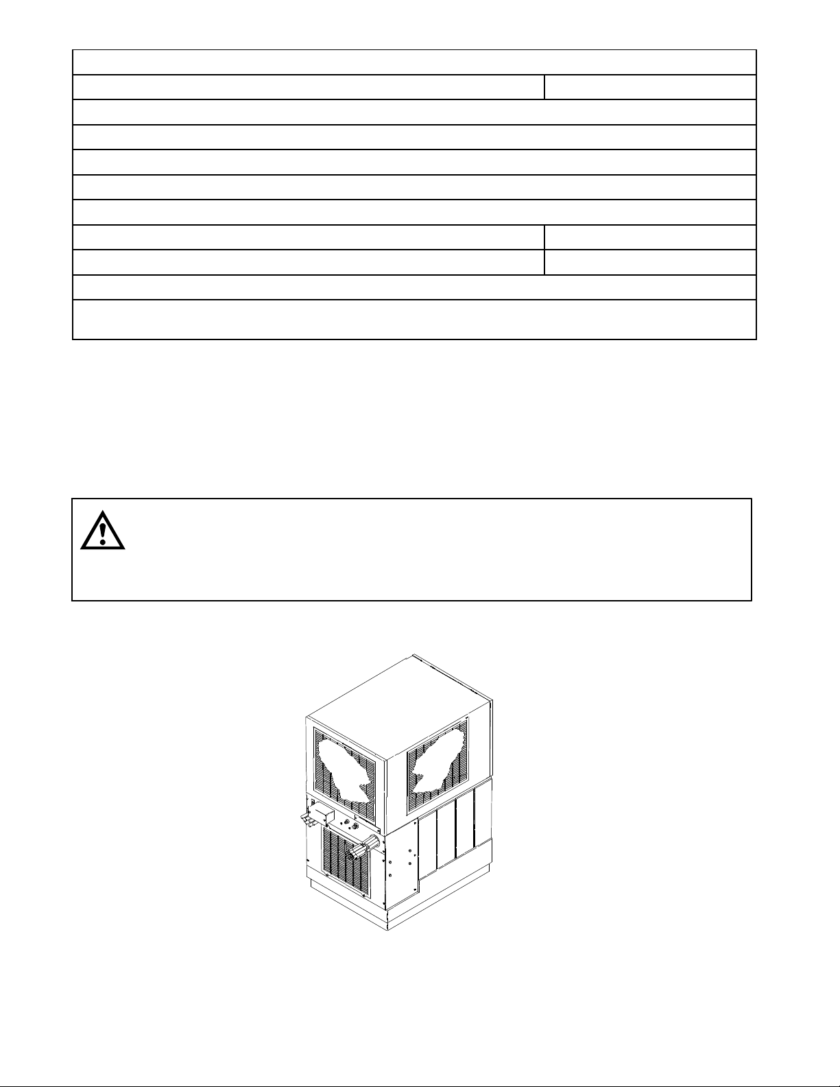
Table 1. Design Data (cont’d)
Ambient Operating Temperature 405 F to 1005 F
Electrical Requirements: See Unit Nameplate
DROP--IN REFRIGERATION ASSEMBLY DATA
Weights:
No Ice Bank 103 pounds
With Ice Bank 142 pounds
Refrigerant Requirement (R-134A Refrigerant) See Unit
Nameplate
DESCRIPTION
To the user of this manual - This manual is a guide for installing, operating, and maintaining this
equipment. Refer to the Table of Contents for page location for detailed information pertaining to
questions that arise during installation, operation, service, or maintenance of this equipment.
CAUTION: Before shipping, storing, or relocating this Unit, the syrup systems must be
sanitized and all sanitizing solution must be purged from the syrup systems. All water must
also be purged from the plain and carbonated water systems. A freezing ambient
environment will cause residual water in the Unit to freeze resulting in damage to internal
components.
FIGURE 1. SENTRY III-A COOLING UNIT
312021001 4
Page 8

WARNING: CO2displaces oxygen. Strict attention must be observed in the prevention of
CO2(carbon dioxide) gas leaks in the entire CO2and soft drink system. If a CO2gas leak is
suspected, particularly in a small area, immediately ventilate the contaminated area before
attempting to repair the leak. Personnel exposed to high concentration of CO2gas will experience
tremors which are followed rapidly by loss of consciousness and suffocation.
The Sentry III-A Post-Mix Cooling Unit with R-134A Refrigerant is designed to provide cooled syrup, carbonated
water, and plain water to the dispensing station(s) connected to the Cooling Unit through an insulated python
(length as ordered).
The lower cabinet of the Cooling Unit consist of carbonated water, plain water, and syrup coils, a water tank
where the coils are located, a carbonator, and a carbonated water circulating pump. The Cooling Unit utilizes a
drop-in refrigeration assembly which contains the refrigeration compressor and a condenser coil and fan assembly as shown in Figure 3).
An optional Cooling Unit Stand (P/N 309802069) is available to elevate the Cooling Unit up off the floor.
THEORY OF OPERATION
A CO2cylinder delivers carbon dioxide gas (CO2) through adjustable CO2regulators to the soft drink tanks and
also to the built--in carbonator located inside the cooling unit. Plain water is pumped into the carbonated water
tank by the water pump and is carbonated by regulated CO2pressure also entering the tank. When dispensing
valve is opened, CO2gas pressure exerted upon the syrup in the soft drink tank, pushes syrup from the tank,
through the cooling unit, through the python, and on to the dispensing valve. Carbonated water is pushed by
CO2gas pressure from the carbonated water tank, through the cooling unit, through the python to the dispensing valve. Syrup and carbonated water meet at the dispensing valve resulting in a carbonated drink being dispensed. Plain water is also available at the dispensing station (s) by passing through the cooling unit, through
the python, and on to the dispensing station. Carbonated water is replenished when carbonated water level inside the carbonator tank drops to a specified level which in turn automatically starts the carbonator water pump
motor. When carbonated water level inside the tank has been replenished, the carbonator water pump motor will
stop. Carbonated water is continuously being circulated from the cooling unit, out through the insulated python
to the dispensing station(s), and back to the cooling unit which maintains liquids in the python at a cold temperature.
3120210015
Page 9

SYRUP INLET
CONNECTIONS
VALVE
SHUTOFF
INLET
2
PLAIN WATER
CO
INLET CONNECTION
CONNECTION
WATER PUMP
CARBONATED
WATER TANK
CARBONATED
CHECK VALVE
COOLING UNIT
DOUBLE LIQUID
LINE LEGEND
PLAIN WATER
CARB WATER
CO2SYRUP
FIGURE 2. SYSTEM FLOW DIAGRAM
CULATING PUMP
CARBONATED WATER CIR-
BARBED
CONNECTORS (9)
9-LINE PYTHON
TO DISPENSING TOWER
PYTHON LINES
1THROUGH 5 and 9 SYRUP
6 PLAIN WATER
7 CARB WATER OUT
UNNUMBERED LINE IS
CARB WATER RETURN
6
Page 10

PARTS IDENTIFICATION
CONDENSER
COIL
CARBONAT ORMOTOR
POWER SWITCH
CIRCULATING MOTOR
POWER SWITCH
CARBONATED WATER
CIRCULATING PUMP
MOTOR
COOLING UNIT UNIT
POWER SWITCH
UNIT ELECTRICAL
BOX
SYRUP INLET LINES
HOOD RETAINING
ACORN NUT
*CONDENSER COIL
AIR FILTER
WATER FILL
HOLE
CONTROL BOX
COMPRESSOR
HOOD
CONDENSER
FAN MOTOR
AGITATOR
MOTOR
SHIPPING
NUT (4)
ACCESS PANEL
RETAINING
SCREW (4)
CO2GAS
INLET
PLAIN WATER
INLET
OUTLET
LINES
LOWER ACCESS
GRILLE
CARBONATED
WATER TANK
CARBONAT OR
WATER PUMP
CAUTION: The refrigeration assembly condenser coil and air
filter must be cleaned every 30 days. Excessive accumulation
of dust, lint, and grease on air filter and coil will restrict cooling air
flow through the coil and cause coil and refrigeration system to
overheat. Operating refrigeration system in an overheated condition
will eventually lead to compressor failure.
FIGURE 3. PARTS IDENTIFICA TION
CARBONAT OR
WATER PUMP
MOTOR
CARBONAT ORWATER PUMP
SAFETY THERMOSTAT
3120210017
Page 11

THIS PAGE LEFT BLANK INTENTIONALLY
312021001
8
Page 12

INSTALLATION
This section covers unpacking and inspection, selecting location, installing cooling unit, preparing cooling unit for
operation, and cooling unit operation.
UNPACKING AND INSPECTION
(See Figure 3)
NOTE: The system was thoroughly inspected before leaving the factory and the carrier has accepted
and signed for it. Any damage or irregularities should be noted at time of delivery (or not later than 15
days from date of delivery) and immediately reported to the delivering carrier. Request a written inspection report from Claims Inspector to substantiate any necessary claim. File claim with the delivering
carrier, not with IMI Cornelius Inc.
1. After cooling unit has been unpacked, remove shipping tape and other packing material.
2. Remove top screw from ground strap securing hood to cooling unit, then remove hood.
3. Unpack LOOSE--SHIPPED PARTS (see Table 2). Make sure all items are present and in good condition.
SELECTING LOCATION
IMPORTANT: Ambient temperature for cooling unit must not exceed 100° F. Several means are available
to achieve proper ambient temperature and air circulation around the unit which are wall air intake
grilles and ceiling exhaust fans, air conditioning, etc. Check local codes (see (4) and (5) below).
Select location for cooling unit installation that will (1) allow shortest possible python run to dispensing station(s)
location(s), (2) is accessible to 208/240VAC, single phase 50/60Hz electrical power circuit fused at 15--amps
(slo--blow) for cooling unit. ALL ELECTRICAL WIRING MUST CONFORM TO NATIONAL AND LOCAL ELECTRICAL CODES, (3) close to a plain water source supply line with proper requirements, (4) a minimum of 6-inches clearance must be provided on sides and back of the Unit and front of the Unit must be open to the room
for proper air circulation in and out of the Unit. (5) a minimum of 36-inches must be provided above the Unit to
the nearest object (shelf, cupboard, or ceiling) to allow removal of the Unit hood and refrigeration system. (6)
close to permanent floor drain to route cooling unit overflow and water tank drain hoses.
Table 2. Loose-Shipped Parts
Item
No. Part No. Name Qty .
1 111353000 Tubing Clamp, Oetiker 145 8
2 111085000 Tubing Clamp, Oetiker 226 4
3 311962000 Label, Line Identification 1
4 398025013 Acorn Nut 1
5 940079 Rubatex, 72-inches Long 1
6 148994198 Tubing Clamp, Oeitiker 198 4
7 309853000 Tubing Clamp, Oeitker 157 18
INSTALLATION
WARNING: Disconnect electrical power to cooling unit to prevent personnel injury before
attempting any internal maintenance. Only qualified personnel should service internal
components or electrical wiring.
3120210019
Page 13

PLACING COOLING UNIT IN OPERATING LOCATION
NOTE: An optional Cooling Unit Stand (P/N 309802069) is available to elevate the Cooling Unit up off
the floor..
To comply with National Sanitation Foundation (NSF) requirements, Cooling Unit must be sealed to floor. Per-
form the following procedure to install Cooling Unit.
1. Place Cooling Unit in operating position meeting requirements of SELECTING LOCATION.
2. Tilt Cooling Unit up to expose bottom of unit base.
3. Liberally apply silastic sealant such as Dow Corning (RTV 731) or equivalent on Cooling Unit base bottom
edges.
NOTE: Do not move Cooling Unit lower cabinet after positioning or seal from unit base to floor will be
broken.
4. Lower Cooling Unit into operating position to complete seal from unit base to floor. Apply additional sealant
around bottom of base. Seal must have a minimum radius of 1/2--inch to prevent cracks and crevices and
to ensure a complete seal.
5. Route Cooling Unit 1/2--inch water tank overflow tube to floor drain.
6. Route Cooling Unit syrup inlet lines (labeled 1 through 6) to soft drink tanks location.
CONNECTING ELECTRICAL POWER TO COOLING UNIT
1. Make sure Cooling Unit power switch is in “OFF” position.
2. Connect 208/240 VAC, single-phase 50/60HZ electrical power circuit fused at 15-amps (slo-blo) to electrical
box on front of the Cooling Unit. ALL ELECTRICAL WIRING MUST CONFORM TO NATIONAL AND LOCAL ELECTRICAL CODES.
FILL UNIT WATER TANK AND START REFRIGERATION SYSTEM
(See Figure 3)
1. Make sure plug in end of the Cooling Unit water tank drain hose is secure.
NOTE: Use low-mineral-content water where a local water problem exist.
2. Remove plug from drop-in refrigeration assembly platform water fill hole. Fill water tank with clean water
until water runs out of water tank overflow hose. USE LOW-MINERAL-CONTENT WATER WHERE A
LOCAL WATER PROBLEM EXIST.
3. Install plug in water fill hole.
IMPORTANT: Make sure carbonator and circulating pump motors power switches, located on cooling
unit electrical box, are both in ‘‘OFF’’ (down) positions before starting refrigeration system. Dry running
carbonator and circulating pumps will result in damage to pumps.
4. Make sure Cooling Unit carbonator and circulating pumps power switches are in ‘‘OFF’’ positions.
WARNING: Disconnect electrical power to Cooling Unit to prevent personnel injury before
attempting any internal maintenance. Only qualified personnel should service internal
components or electrical wiring.
312021001
10
Page 14

5. Place Cooling Unit power switch in ‘‘ON’’ (up) position. Compressor and agitator motor will start and begin
forming an ice bank. When full ice bank has been formed, compressor will stop but agitator motor will continue to operate circulating water in water tank.
CONNECTING PLAIN WATER SOURCE TO UNIT
(See Figure 2)
NOTE: IMI Cornelius Inc. recommends that a water shutoff valve be installed in plain water inlet supply
line connected to water filter assembly.
CAUTION: Check water flow rate of plain water inlet supply line. MINIMUM FLOW RATE
MUST BE AT LEAST 150--GALLONS PER HOUR. If flow rate is less than 150--gallons per
hour, starving of carbonator water pump will occur. Starving will allow water pump to
overheat causing safety thermostat on pump outlet to disrupt electrical power to and stop water
pump motor. Carbonated water circulating pump over--heating could occur and possibly damage
pump if carbonator is not providing adequate carbonated water supply . CARBONATOR CO
PRESSURE MUST EXCEED WATER PRESSURE BY 10--PSI. (Example: operating CO2pressure is
80--psi and maximum water pressure can be no more than 70--psi, etc.)
CO2operating pressure must be a minimum of 80-psi with a maximum of 125-psi and water
pressure must be a minumum of 35-psi with a maximum of 115-psi.
Connect plain water source line to 5/8-18 bulkhead fitting on the Cooling Unit labeled “PLAIN WATER INLET”.
DO NOT TURN ON WATER SUPPLY TO THE UNIT AT THIS TIME.
2
CONNECTING CO2SOURCE LINE TO UNIT
(See Figure 2)
Connect CO2source line, from a regulated CO2source, to 1/4-male bulkhead fitting on the Cooling Unit labeled
“CO2GAS INLET”. DO NOT TURN ON CO2GAS SUPPLY TO UNIT AT THIS TIME.
CONNECTING SYRUP SOURCE LINES TO UNIT AT THIS TIME
1. Connect syrup source lines (routed from syrup tanks location) to Cooling Unit inlet lines labeled “SYRUP
INLET”.
2. Install syrup tanks quick disconnects on ends of the syrup source lines. DO NOT CONNECT SYRUP
TANKS INTO SYRUP SYSTEMS AT THIS TIME.
CONNECTING INSULATED TRUNK PYTHON TO UNIT
1. Route insulated trunk python from Cooling Unit location up to and connect to the dispensing station(s).
2. Connect insulated trunk python to Cooling Unit syrup, carbonated water, and plain water outlet lines labeled
“PYTHON CONNECTION”. Secure connections with TUBING CLAMPS (items 1, 2, 6, and 7. DO NOT INSULATE TUBING CONNECTIONS AT THIS TIME.
PREPARATION FOR OPERATION
WARNING: CO2displaces oxygen. Strict attention must be observed in the prevention of
CO2(carbon dioxide) gas leaks in the entire CO2and soft drink system. If a CO2gas leak is
suspected, particularly in a small area, immediately ventilate the contaminated area before
attempting to repair the leak. Personnel exposed to high concentration of CO2gas will experience
tremors which are followed rapidly by loss of consciousness and suffocation.
31202100111
Page 15

WARNING: To avoid personal injury and/or property damage, always secure CO2cylinder in
upright position with a safety chain to prevent it from falling over. Should the valve become
accidentally damaged or broken off, CO2cylinder can cause serious personal injury.
CAUTION: Before connecting primary CO2regulator assembly to the CO2cylinder, turn all
CO2regulators adjusting screws to the left (counterclockwise) until all tension is relieved
from the adjusting screws.
ADJUSTING CO2REGULATORS
Carbonator CO2regulator
Adjust carbonator CO2regulator to a minimum of 80-psi with a maximum of 125-psi. CO2pressure to the carbonator must not exceed 125-psi.
Sugar Syrup Tank CO2Regulator
Adjust syrup tanks secondary CO2regulator at 40-psi for syrup lines up to 10-feet in length plus one pound for
each additional length of 10-feet plus one pound for each 2-feet of vertical lift. For example: If syrup line total
length is 30-feet and total vertical lift is 6-feet, then 40-psi + 2-psi (1-psi for every 10-feet of length over 10-feet
which is 20-feet) + 3-psi (1-psi for every 2-Feet of vertical lift which is 6-feet); total equals 40 + 2 + 3= 45-psi
CO2regulator setting.
Low-Calorie (diet) Syrup Tank CO2Regulator
Adjust low-calorie (diet) syrup tank secondary CO2regulator to 10-psig for syrup lines up to 30-feet in length.
Syrup lines longer than 30-feet in length may require a slightly higher CO2regulator setting of 12-psig maximum.
Excessive CO2pressure may cause low-calorie syrup carbonation resulting in foam.
ACTIVATING PLAIN WATER SOURCE AND STARTING CARBONATOR
1. Make sure shutoff valve, located inside the Cooling Unit, (see Figure 2) in Unit plain water outlet line is in
the “OFF” position.
2. Open plain water source shutoff valve. Check for water leaks and repair any leaky connections.
3. Place carbonator power switch, located on Cooling Unit electrical box (see Figure 3), labeled “CARB
MOTOR” in “ON” (up) position.
4. Check entire system for leaks and repair any leaky connections.
STARTING CARBONATED WATER CIRCULATING PUMP
1. Dispense carbonated water from dispensing station until all air is purged from carbonated water system.
2. Place carbonated water circulating pump power switch, located on cooling unit electrical box (see Figure 3),
labeled CIRC MOTOR in ‘‘ON’’ (up) position. Circulating pump will start and began circulating carbonated
water through system. Dispense carbonated water from dispensing station to make sure all air is purged
from carbonated water system.
312021001
12
Page 16

3. Check for water leaks and tighten or repair any leaky connections.
ACTIVATING SYRUP SYSTEMS
IMPORTANT: Syrup systems must be sanitized as instructed in Operator’s Manual (P/N 312021002)
before syrup is connected into the syrup systems.
1. Connect syrup tanks into syrup systems.
2. Dispense from dispensing station(s) until all air is purged from syrup systems and syrup is dispensed.
3. Check for syrup leaks and tighten or repair any leaky connections.
INSULATING PYTHON CONNECTION TO COOLING UNIT
1. After syrup, plain water, and carbonated water systems have been activated and are in operation, check
Cooling Unit inlet and outlet line connections for leaks. If leaks are present, repair as necessary .
2. Cut piece of RUBATEX (item 5) across its entire length in preparation to wrap around python lines connections to Cooling Unit outlet lines.
3. Wrap rubatex around exposed lines and secure with duct tape. MAKE SURE AFTER RUBATEX IS IN
PLACE, ITS ENDS BUTT UP TIGHTLY AGAINST PYTHON INSULATION ON ONE END AND COOLING
UNIT ON OTHER END.
4. Leak check, then insulate all exposed insulated trunk python and branch python connections.
5. Install hood on Cooling Unit and secure with ACORN NUT (item 4).
6. Install screw in hood ground strap to secure strap to hood.
INSTALLING LINE IDENTIFICATION LABEL
Install LABEL, LINE IDENTIFICATION (item 3) on side of cooling unit and record syrup flavors in proper spaces.
31202100113
Page 17

RELAY
AGITATOR MOTOR
GREEN
RUN CAPACITOR
START CAPACIT OR
FIGURE 4. WIRING DIAGRAM (DROP-IN REFRIGERATION ASS’Y)
FAN MOTOR
ICE BANK CONTROL
RELAY
CONTROL BOX
TERMINAL BLOCK
GREEN
BLACK
WHITE OR
BLUE
312021001
FIGURE 5. WIRING DIAGRAM (LOWER COOLING UNIT CABINET)
14
Page 18

TROUBLESHOOTING
IMPORTANT: Only qualified personnel should service internal components or electrical wiring.
WARNING: If repairs are to be made to carbonated water system, disconnect electrical
power to Cooling Unit, shut off plain water and CO2supplies, and relieve the carbonated
water system pressure before proceeding. If repairs are to be made to syrup system,
remove quick disconnects from applicable syrup tank, then relieve the system pressure before
proceeding. If repairs are to be made to CO2system, stop dispensing, shut off CO2supply , then
relieve the system pressure before proceeding.
TROUBLESHOOTING SENTRY III--A POST--MIX COOLING UNIT
Trouble Probable Cause Remedy
DISPENSED PRODUCT
CARBONATION TOO LOW.
ONLY SYRUP DISPENSED. A. Plain water inlet supply line
WARM PRODUCT BEING
DISPENSED
A. Carbonator CO2regulator out
of adjustment for existing
water conditions or
temperature.
B. Water, oil, or dirt in CO2supply B. Remove contaminated CO
shutoff valve closed.
B. Carbonator power switch in
‘‘OFF’’ position.
C. Carbonator inoperable. C. Repair carbonator.
D. Water filter clogged. D. Replace water filter.
A. Carbonated water circulating
pump power switch in “OFF”
position.
B. Inoperable carbonated water
circulating pump or motor.
TROUBLESHOOTING CARBONATOR
A. Adjust carbonator CO2regulator
as instructed.
2
supply . Clean CO2system (lines,
regulators,etc.) using a mild
detergent. Replenish with a clean
CO2supply .
A. Open plain water inlet supply line
shutoff valve.
B. Place carbonator power switch in
‘‘ON’’ position.
A. Place circulating pump power
switch in “ON” position.
B. Replace pump or motor.
Trouble Probable Cause Remedy
WATER PUMP WILL NOT
OPERATE
A. Carbonator power switch in
“OFF” position.
B. Inoperative water pump motor. B. Replace water pump motor.
C. Dirty balance mechanism. C. Clean balance mechanism.
D. Loose connections and/or
open electrical circuit.
A. Place switch in “ON” position.
D. Tighten connections and/or repair
open circuit.
31202100115
Page 19

Trouble Probable Cause Remedy
WATER PUMP WILL NOT
OPERATE (CONT’D)
WATER PUMP MOTOR WILL
NOT SHUT OFF.
E. Overheated motor cut off by
thermal overload protector.
E. Check for proper line voltage.
Check for restricted pump
discharge.
F. Inoperative level control
F. Replace level control switches.
switches.
G. Binding or damaged balance
mechanism.
H. Water pump binding (new or
replacement pumps only).
G. Repair or replace balance
mechanism.
H. Remove water pump from motor,
rotate pump or motor shaft 180
degrees, then recouple pump to
motor.
I. Water pump damaged. I. Replace water pump as
instructed.
J. Safety thermostat inoperative. J. Replace safety thermostat.
A. Foreign object restricting tank
A. Remove foreign object.
movement.
B. Dirty balance mechanism. B. Clean balance mechanism.
C. Leak in carbonated water line. C. Tighten or replace line.
D. Inoperative level control
D. Replace level control switches.
switches.
ERRATIC CYCLING OF
CARBONATOR.
WATER PUMP MOTOR
OPERATES BUT WATER
PUMP DOES NOT PUMP
WATER.
WATER PUMP CAPACITY TOO
LOW.
E. Binding or damaged balance
mechanism.
A. Balance mechanism spring
obstructed or ‘‘cocked’’.
E. Repair or replace balance
mechanism.
A. Remove obstruction. Make sure
spring is perpendicular to spring
release and is not twisted.
B. Dirty balance mechanism. B. Clean balance mechanism.
A. Water pump inlet water strain
screen dirty.
A. Clean or replace water strainer
screen as instructed.
B. Kinked water supply line. B. Straighten water supply line.
C. Restriction between water
C. Remove restriction.
pump outlet and carbonator
tank inlet.
D. Foreign object in water pump
bypass.
D. Clean. (Note: Count number of
turns bypass screw makes when
removing and install same
number of turns.)
E. Water pump worn out. E. Replace water pump.
A. Water pump inlet water
strainer screen dirty.
A. Clean or replace water strainer
screen as instructed.
B. Water supply capacity too low. B. Inlet water supply must be at a
312021001 16
minimum of 150--gallons per hour
with a maximum water pressure
of 70--psi.
Page 20

Trouble RemedyProbable Cause
WATER PUMP CAPACITY
C. Water filter clogged. C. Replace water filter cartridge as
TOO LOW (CONT’D)
D. Inoperative water pump. D. Replace water pump.
TROUBLESHOOTING REFRIGERATION SYSTEM
Trouble Probable Cause Remedy
COMPRESSOR DOES NOT
A. Ice bank sufficient. A. Refrigeration not called for
OPERATE.
B. Electrical power to cooling unit
turned off.
C. No cooling unit power source.
Blown fuse or tripped circuit
breaker.
D. Low voltage. D. Voltage must be at least 208 volts
E. Loose, disconnected, or
broken wiring.
F. Compressor overloaded
protector cutout;overheated
compressor.
a.
Dirty and obstructed condenser
coil or inoperable condenser fan
motor.
instructed.
B. Turn on electrical power to cooling
unit or plug in refrigeration system
power cord.
C. Replace fuse or reset circuit
breaker.
at compressor terminals when
compressor is trying to start.
E. Tighten connections or replace
broken wiring.
F. Locate problem and correct. (See
CLEANING CONDENSER COIL
in SERVICE AND
MAINTENANCE.
COMPRESSOR WILL NOT
STOP AFTER SUFFICIENT
ICE BANK IS PRODUCED.
(NOTE--ICE BANK SHOULD
JUST COVER CONTROL
BULB.)
G. Inoperative overload protector
G. Replace inoperative part.
or start relay.
H. Inoperative ice bank control. H. Replace ice bank control.
I. Inoperative compressor. I. Replace compressor.
A. Ice bank control cap tube
A. Replace ice bank control.
kinked or broken.
B. Ice bank control stuck in
B. Replace ice bank control.
closed position.
31202100117
Page 21

Trouble RemedyProbable Cause
COMPRESSOR OPERATES
CONTINUOUSLY BUT DOES
NOT FORM SUFFICIENT ICE
BANK.
CONDENSER FAN MOTOR
NOT OPERATING.
A. Cooling capacity is exceeded
by overdrawing.
B. Cooling unit located in
excessively hot area or air
circulation through condenser
A. Reduce amount of drinks drawn
per given time.
B. Relocate unit or check and if
necessary , clean condenser coil
as instructed.
coil is restricted
NOTE: Ice bank freezes from bottom of evaporator upward. A refrigerant
leak or insufficient charge might show an ice bank at bottom and not at
top of evaporator.
A. Jumper cord loose or
disconnected from condenser
fan motor or compressor
terminals. Broken wire in cord.
B. Fan blade obstructed. B. Remove obstruction.
C. Inoperative condenser fan
motor.
NOTE: If overload protector cuts out compressor, condenser fan motor
will continue to operate otherwise; troubleshooting condenser fan motor
problems is same as for ‘‘COMPRESSOR DOES NOT OPERA TE’’
paragraph plus the following:
A. Tighten connections or replace
cord.
C. Replace condenser fan motor.
AGITATOR MOTOR NOT
OPERATING.
A. Agitator motor propeller
A. Remove obstruction.
obstructed.
B. Low voltage. B. Voltage must be at least 208 volts
at compressor terminals when
compressor is trying to start.
C. Loose, disconnected, or
broken wiring.
C. Tighten connections or replace
broken wiring.
D. Inoperative agitator motor. D. Replace agitator motor.
312021001 18
Page 22

WARRANTY
IMI Cornelius Inc. warrants that all equipment and parts are free from defects in material and workmanship under normal use and service. For a copy of the warranty applicable to your Cornelius, Remcor or
Wilshire product, in your country, please write, fax or telephone the IMI Cornelius office nearest you.
Please provide the equipment model number, serial number and the date of purchase.
IMI Cornelius Offices
AUSTRALIA D P.O. 210, D RIVERWOOD, D NSW 2210, AUSTRALIA D (61) 2 533 3122 D FAX (61) 2 534 2166
AUSTRIA D AM LANGEN FELDE 32 D A-1222 D VIENNA, AUSTRIA D (43) 1 233 520 D FAX (43) 1-2335-2930
BELGIUM D BOSKAPELLEI 122 D B-2930 BRAASCHAAT, BELGIUM D (32) 3 664 0552 D FAX (32) 3 665 2307
BRAZIL D RUA IT AOCARA 97 D TOMAS COELHO D RIO DE JANEIRO, BRAZIL D (55) 21 591 7150 D FAX (55) 21 593 1829
ENGLAND D TYTHING ROAD ALCESTER D WARWICKSHIRE, B49 6 EU, ENGLAND D (44) 789 763 101 D FAX (44) 789 763 644
FRANCE D 71 ROUTE DE ST. DENIS D F-95170 DEUIL LA BARRE D PARIS, FRANCE D (33) 1 34 28 6200 D FAX (33) 1 34 28 6201
GERMANY D CARL LEVERKUS STRASSE 15 D D-4018 LANGENFELD, GERMANY D (49) 2173 7930 D FAX (49) 2173 77 438
GREECE D 488 MESSOGION AVENUE D AGIA PARASKEVI D 153 42 D ATHENS, GREECE D (30) 1 600 1073 D FAX (30) 1 601 2491
HONG KONG D 1104 TAIKOTSUI CENTRE D 11-15 KOK CHEUNG ST D TAIKOKTSUE, HONG KONG D (852) 789 9882 D FAX (852) 391 6222
ITALY D VIA PELLIZZARI 11 D 1-20059 D VIMARCATE, ITAL Y D (39) 39 608 0817 D FAX (39) 39 608 0814
NEW ZEALAND D 20 LANSFORD CRES. D P.O. BOX 19-044 AVONDALE D AUCKLAND 7, NEW ZEALAND D (64) 9 8200 357 D FAX (64) 9 8200 361
SINGAPORE D 16 TUAS STREET D SINGAPORE 2263 D (65) 862 5542 D FAX (65) 862 5604
SPAIN D POLIGONO INDUSTRAIL D RIERA DEL FONOLLAR D E-08830 SANT BOI DE LLOBREGAT D BARCELONA, SPAIN D (34) 3 640 2839 D FAX (34) 3 654 3379
USA D ONE CORNELIUS PLACE D ANOKA, MINNESOTA D (612) 421-6120 D FAX (612) 422-3255
LD004
4/21/98
31202100119
Page 23

Page 24

IMI CORNELIUS INC.
CORPORATE HEADQUARTERS:
One Cornelius Place
Anoka, Minnesota 55303-6234
(763) 421-6120
(800) 238-3600
 Loading...