

Reliable 9000IS, 9000CJ, 9500BU, 9000CD User Manual
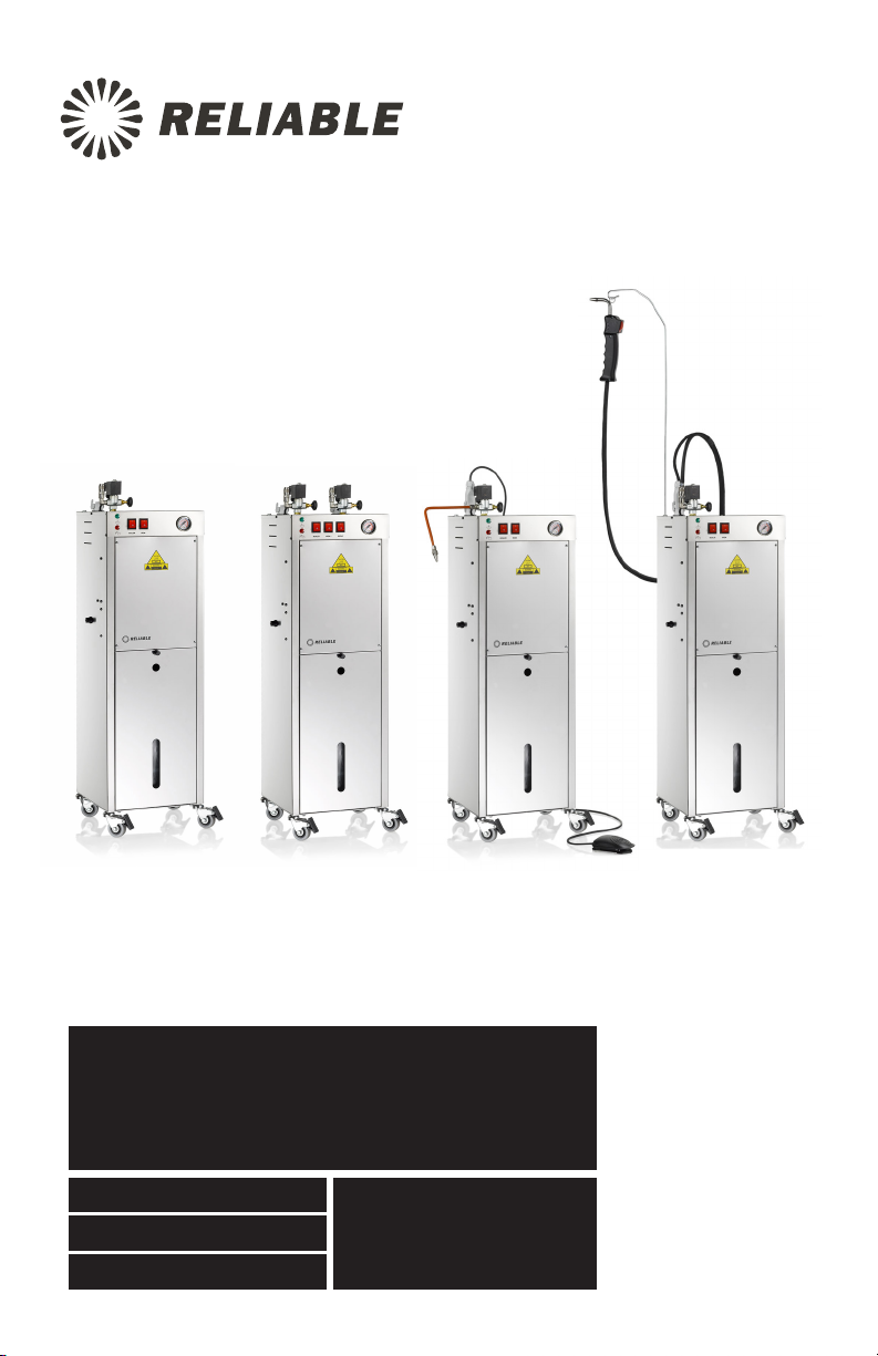
9000IS 9000CJ 9000CD9500IS
9000 SERIES
PROFESSIONAL STEAM PRODUCTS
PRODU ITS À VAPEUR PROFES SIONNELS
PRODU CTOS PROFESIO NALES DE VAPOR
INSTRUCTION MANUAL
GUIDE D’UTILISATION
MANUAL DE INSTRUCCIONES


ENGLISH 01
FRANÇAIS 16
ESPAÑOL 29

THE 9000
PROFESSIONAL STEAM PRODUCTS
INSTRUCTION MANUAL
ENGLISH
01

RELIABLE. RIGHT THERE WITH YOU.
At Reliable, we do what we love, and take pride in doing it right.
You want what’s best for the people, places and things that matter
in your life – from where you live to what you wear. So do we. From
the start, we approach every product with a craftsman’s attention
to detail and passion for making it right. Quality, functionality,
design and customer service play an equally important part in
delivering what’s right for you. With its stainless steel construction,
and professional grade components; the 9000 Series will allow
you to obtain the benefits of professional pressing or cleaning in a
compact and convenient format.
For your safety and to fully enjoy the advantages of this product,
please take a few minutes to read all the important safeguards and
care instructions. Keep this manual handy and review the product
warranty for your reference.
02
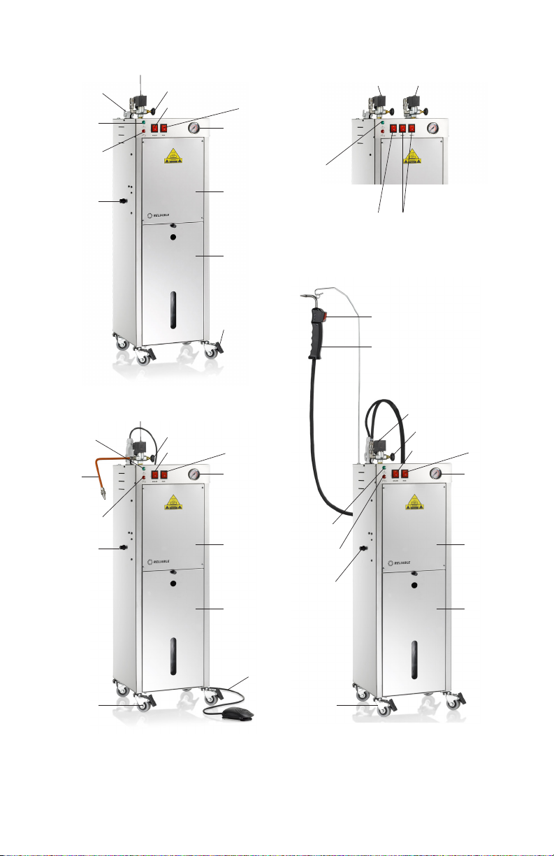
IRON PLUG
LOW WATER
PILOT LIGHT
STEAM READY
PILOT LIGHT (C)
ELECTRICAL
CABLE INLET
SOLENOID VALVE
STEAM REGULATION VALVE
STEAM SWITCH (B)
9000IS/9500IS 9500IS
BOILER SWITCH (A)
PRESSURE GAUGE
H
WATER DISCHARGE
BE
WATER INLET
LOW WATER
PILOT LIGHT
STEAM
NOZZLE
STEAM READY
PILOT LIGHT
ELECTRICAL
CABLE INLET
HEAVY DUTY
CASTERS
HEAVY DUTY
CASTERS
SOLENOID VALVE SOLENOID VALVE
STEAM REGULATION VALVE STEAM REGULATION VALVE
STEAM SWITCH STEAM SWITCH
BOILER SWITCH BOILER SWITCH
PRESSURE GAUGE PRESSURE GAUGE
LOW WATER
WATER
DISCHARGE
WATER INLET WATER INLET
FOOT PEDAL
PILOT LIGHT
STEAM READY
PILOT LIGHT
ELECTRICAL
CABLE INLET
HEAVY DUTY
CASTERS
STEAM GUN SWITCH
STEAM WAND
WATER
DISCHARGE
03
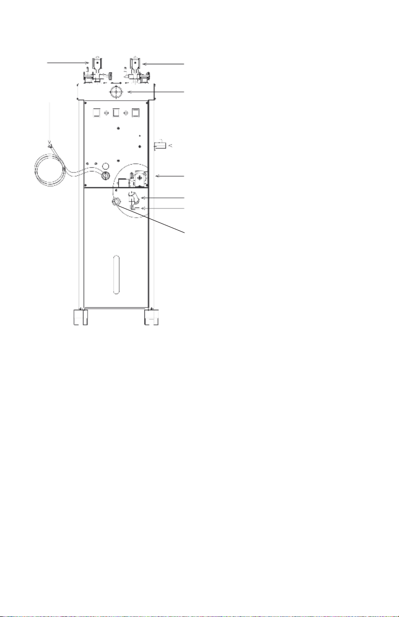
Fig. 5
6
1 = water inlet
77.1
2 = water filter
5
3 = pump
4 = water discharge
5 = pressure gauge
6 = power inlet
4
7 = solenoid valve
7.1 = solenoid valve
3
8 = water container valve
2
1
8
04

THE INSTALLATION AND USE OF THIS
PROFESSIONAL EQUIPMENT MUST BE DONE
BY COMPETENT AND TRAINED PERSONNEL
WITH APPROPRIATE TECHNICAL KNOWLEDGE
AND UNDERSTANDING OF APPLICABLE SAFETY
STANDARDS. BEFORE USING THIS EQUIPMENT
IT IS NECESSARY TO CONDUCT THE FOLLOWING
STEPS:
1. Water connection (tap with hose holder); the steam generator will be connected to the tap with hose holder labelled WATER INLET (fig. 5 #1), placed
on the Boiler, via a rubber tube which must have a pressure capacity of at
least 100 lbs. This rubber tube must be fixed tightly with 2 hose clamps.
(NOTE: before inserting the rubber tube into the water inlet, you must flush a
few litres of water in order to clean the conduit).
2. Protected electrical plug, suitable to the power voltage of the
steam generator.
3. 9000IS - Screw the nozzle into the steam fitting and plug in the 4-pin
receptacle for the electronic foot pedal. 9000CD - Connect the steam gun or
steam brush the same way using the quick disconnect steam hose.
4. 9000IS/9500IS - Insert the two-piece wand into the flange on top of the
boiler, tighten with the side screw and attach the spring on the iron hose to
the coil end of the wand.
PACKAGE OPENING
1. Remove the Boiler from the box, affix the wands, connect iron sockets and
steam tubes, fix the iron cable to cable/steam wand support hook.
ATTENTION: irons must be placed on their iron rests, on the ironing board.
CONNECTION TO WATER PIPE AND STARTING
1. Connect the rubber tube to the tube holder called WATER INLET placed on
the steam generator and turn the water tap on.
2. Connect the power supply cable to a protected plug with a grounded switch,
and a voltage suitable to the steam generator voltage.
3. After switching on the Boiler (A) and the irons and the steam switch (B), wait
for the Boiler green pilot light to switch off (C) and for the pressure gauge
to indicate 50-60 lbs. At this point press the steam button 3 or 4 times, so
that the steam comes out: this must be carried out in order to heat up the
05

hose that delivers steam to the iron steam wand/nozzle. This prevents water
leakage (the steam iron must always be held in such a way as not to harm the
operator.
4. To adjust steam flow, regulate the steam adjustment tap (fig. 5/7.1: solenoid
valve).
5. The Boiler is now ready for use. During use, the “steam ready” pilot light
switches on and off (C).
ATTENTION: Make sure that water is always available for the steam generator, the
lack of water can cause air bubbles inside the conduit, i.e. the water will not reach
the Boiler while the Boiler is under pressure. Without water, the pump will function
for about a minute; after that the alarm will sound and will cause the automatic
shut down of the entire unit.
6. Water pressure should never go over 3.5 lbs, otherwise the pump will stop
and, accordingly, the water will not reach the Boiler.
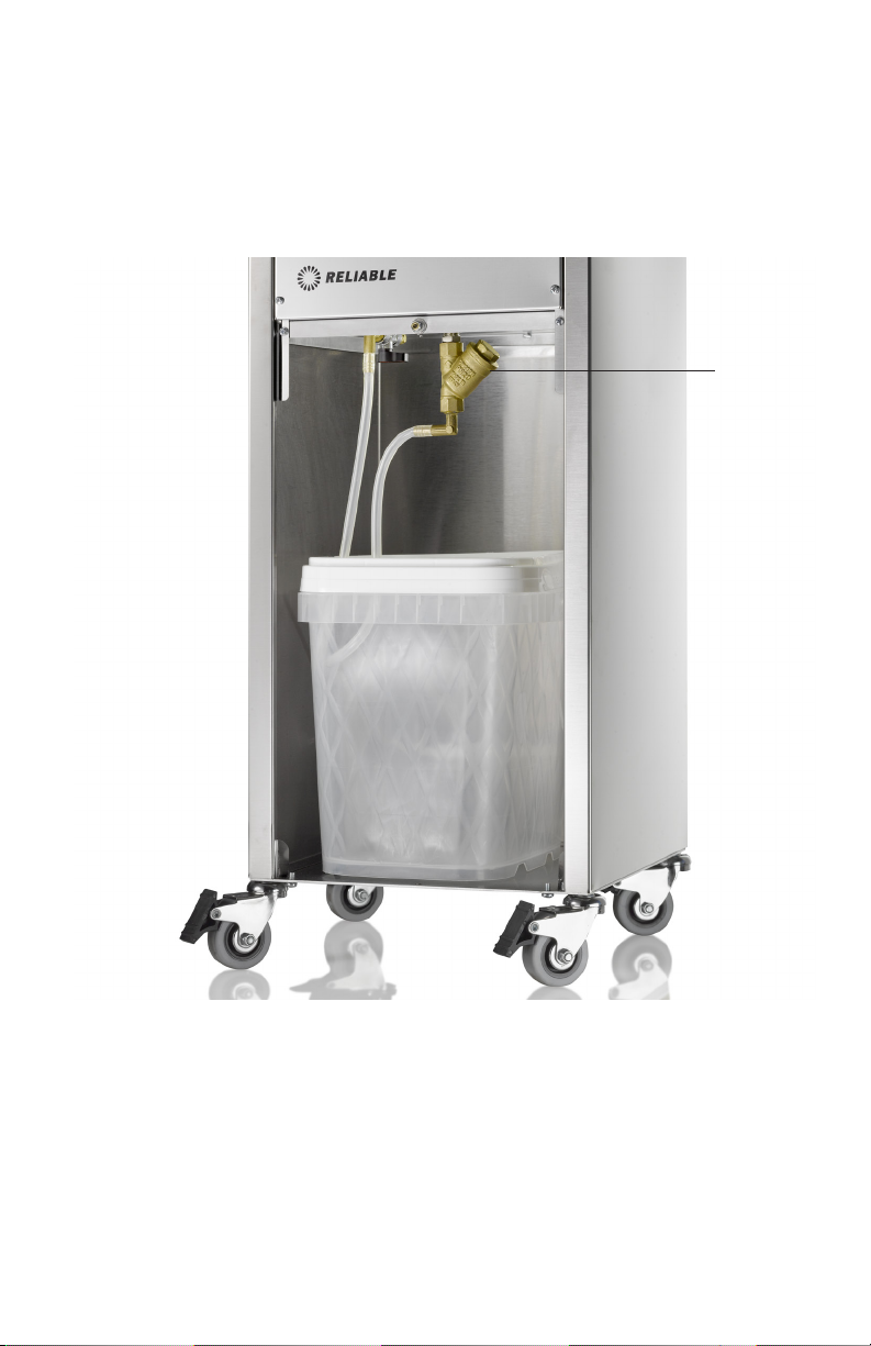
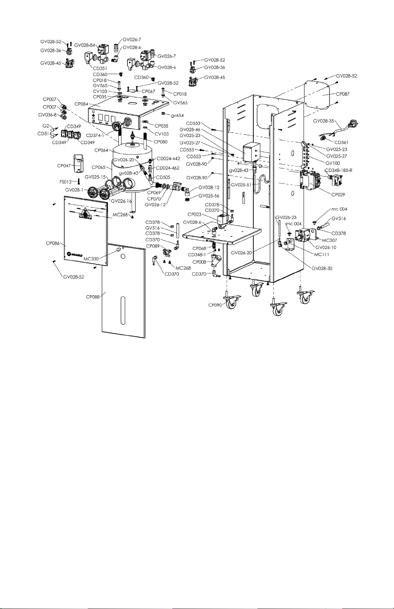
CONNECTION TO THE WATER TANK
1. The Boiler is designed to be connected to a direct waterfeed. If a direct waterfeed source is not available a water container kit is available.
*IF USING THE WATER CONTAINER KIT ENSURE THAT THE VALVE TO THE DIRECT FEED IS IN THE CLOSED POSITION.
2. To assemble the kit please proceed as follows:
• Open the front panel unscrewing the 4 screws.
• Insert the silicon hose on the valve MC111 and place the opposite end
into the water tank.
• Insert the other silicon hose on the water inlet (1), placing the other end
into the water tank.
06
CPO89
07

IMPORTANT
1. Use only tap water.
2. Flush the Boiler once a week, making sure that the unit is shut off and that
the Boiler pressure is not over 0 lbs (pressure gauge). Open exhaust tap
slowly (water discharge). During this operation wear appropriate regulation
gloves, in order to avoid burns.
3. Never leave hot iron on the ironing board.
4. Connect the Boiler to suitable protected plug.
5. When not in use, switch the Boiler off and close the water tap; remember
to open the water tap before switching on the machine again (only for the
units connected to the direct waterfeed).
6. Always keep children away from the Boiler, both when it is on and off.
7. Make sure that during cold seasons the tubes that connect the Boiler to
water supply do not freeze.
8. Do not put additives in the water.
9. Standard and extraordinary maintenance must be carried out by authorized
personnel and all the components must be replaced only with original spare
parts.
08
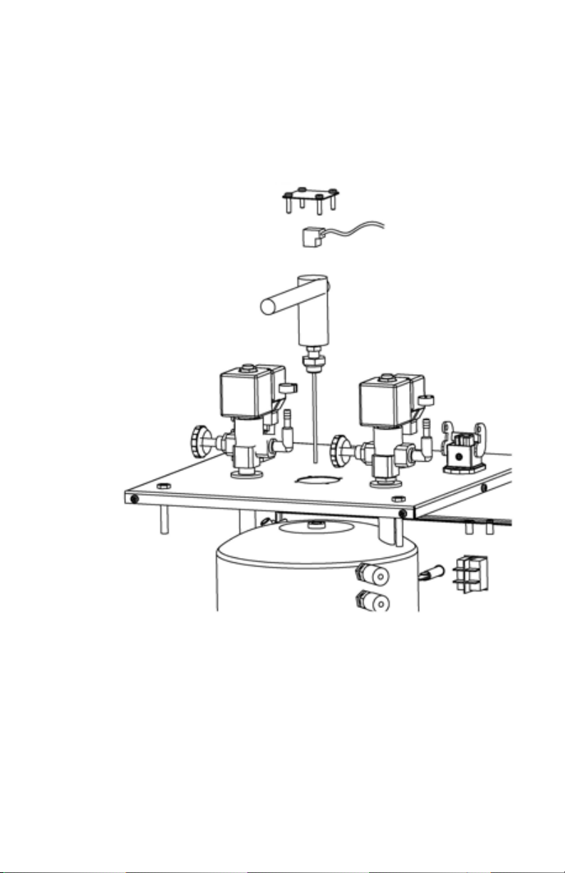
WATER LEVEL PROBE CLEANING PROCEDURE
We recommend you clean the water level probe once a month. This cleaning operation must be carried out ONLY by authorized personnel. Please follow the cleaning
instructions as indicated below:
1. REMOVE THE COVER OF THE LEVEL PROBE
2. REMOVE THE CONNECTION PLUG
3. UNSCREW THE LEVEL PROBE WITH
A TUBE SPANNER DIAM. 18MM
4. TAKE OUT THE LEVEL PROBE
09

SPECIFICATIONS
Version 220V/110V Power supply:
Total Installed Power 1200W:
(Power Iron: W 800)
Boiler Power:
Pump Power: W 48-HZ 50 2/1 mm c f
Boiler Capacity: 5 L/1.3 Gal
Ironing Endurance: CONTINUOUS
Operating Steam Pressure: 3,5 / 4 BAR
Maximum Pressure: 5,5 BAR
IMPORTANT INFORMATION FOR CORRECT
DISPOSAL OF THE PRODUCT
This product must not be disposed of as urban waste. It must be taken to a special
local waste collection centre or to a dealer providing this service.
10
*
Foot Pedal – GVO28/71 (9000CJ)
Steam Nozzle – GVO28/67 (9000CJ)
Steam Gun – 1700DA (9000CD)
11

12
 Loading...