

Page 1
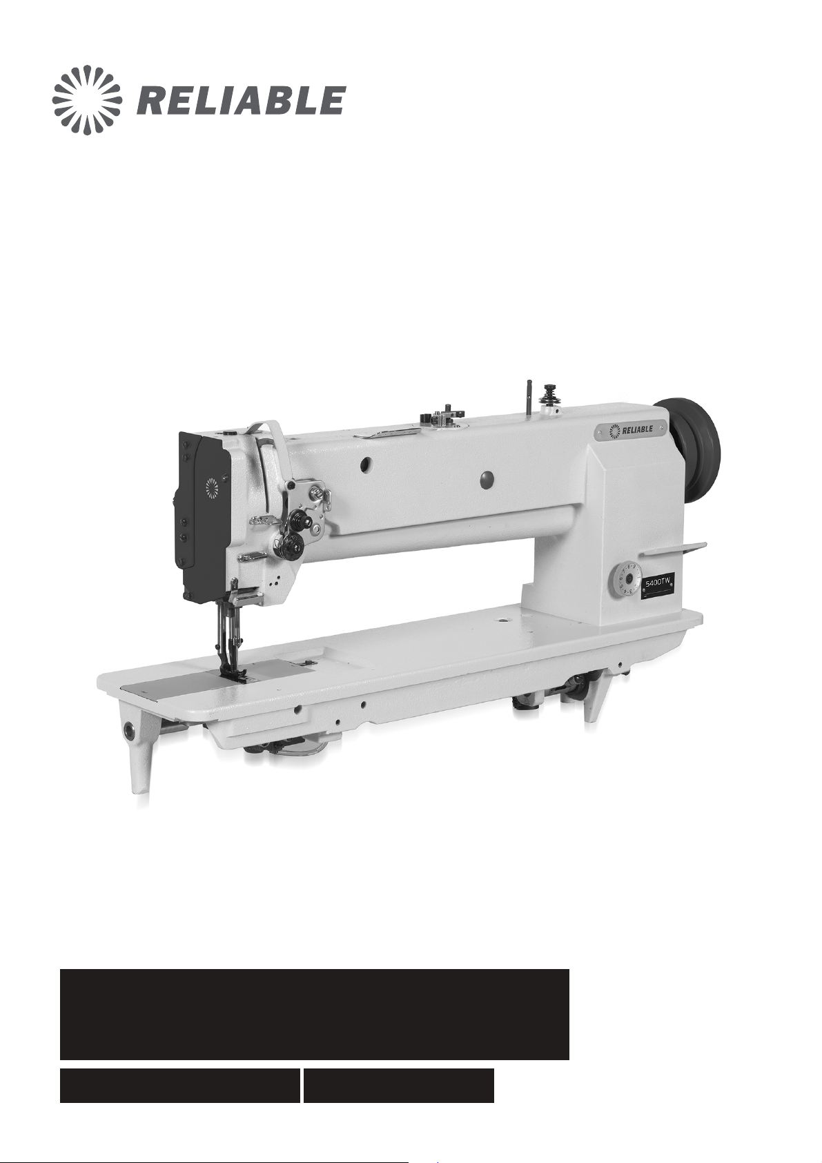
5400SW/5400TW
INDUSTRIAL SEWING MACHINE INSTRUCTION MANUAL
Page 2

CONTENTS
Operation instruction
1. Brief introduction 1
2. Main specifications 1
3. Machine installation and operation preparation 1
1. Machine installation 1-3
2. Operation preparation and notice before running 3-4
4. Machine operation 5-6
1. Coordination among needle, thread and materials 5
2. Install the needle 5
3. Winding the bobbin thread 5-6
5. Machine adjustment 6-9
1. Adjust the needle thread tension and bobbin thread tension 6-7
2. Adjust the pressure of presser foot 7
3. Adjust the safety clutch device 7-9
Parts manual
1.
5400TW machine casting components
2.
5400SW machine casting components
3. Upper shaft and presser foot components 18-19
4. Needle bar and lower feed components 20-23
5. Lower shaft thread looping components 24-25
6. Stitch length adjustment components 26-27
7. Knee lifter and winding components 28-29
8. Lubrication components 30-31
9. Accessories 32-33
10-13
14-17
Page 3

Operation instructions
Page 4
5400TW machine adopts straight double needle and two
vertical auto-lubricating hooks for thread looping,
sliding lever for thread take up to form two lines of
lockstitch seam. The upper and lower shafts are
supported by needle bearing and driven by
toothed belt, plunger oil pump lubrication system,
compound feed mechanism of feed dog, walking
foot and needle, so even if for long stitch length or
sewing long materials, it can deal with them freely. .
5400SW sewing machine adopts single
straight needle and vertical auto-lubricating hook for
thread looping, it has all of the advantages of
5400TW. .
Model
Applications
Max. Sewing speed
Max. Stitch length
Needle bar stroke
Presser foot lift height
Hook
Needle
Needle gauge
Lubrication
5400TW
Medium and heavy weight materials
1200s.p.m
9mm
36mm
8mm by hand
More than 16mm by pedal
Large vertical auto-lubricating hook
DP 17 Nm125 180
6.4mm (standard)
Auto-lubricating
5400SW
Both of the models are widely used in the factories
of suitcase, tent, cushion, leather goods, apparel,
mat, etc.
1. Machine installation
1.1 Location of the machine
The machine must be located on the rigid and flat
floor for ensuring its smooth operation and reducing
its vibration. Meanwhile, a rubber mat should be
inserted between the machine stand and the floor for
further reducing the running noise. .
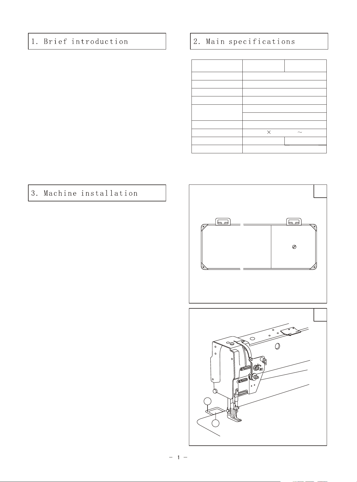
1.2 Install the oil pan (Fig. 1)
Put the oil pan into the table cutout and place the
four cushions on the four corners of the cutout,
finally fix the cushion and oil pan on the table by
nail. .
Special needle gauge available (mm):3.2,4,4.8,8,
9.5,12.7,16,19,25.4.
.
1
2
1.3 Install the machine head (Fig. 2)
Make the hinge A of machine head engaged with
hinge socket B on the table, then turn the machine
head till it is seated on the frame of table cutout,
please keep the turning freely. .
B
A
Page 5

E
D
A
B
C
3
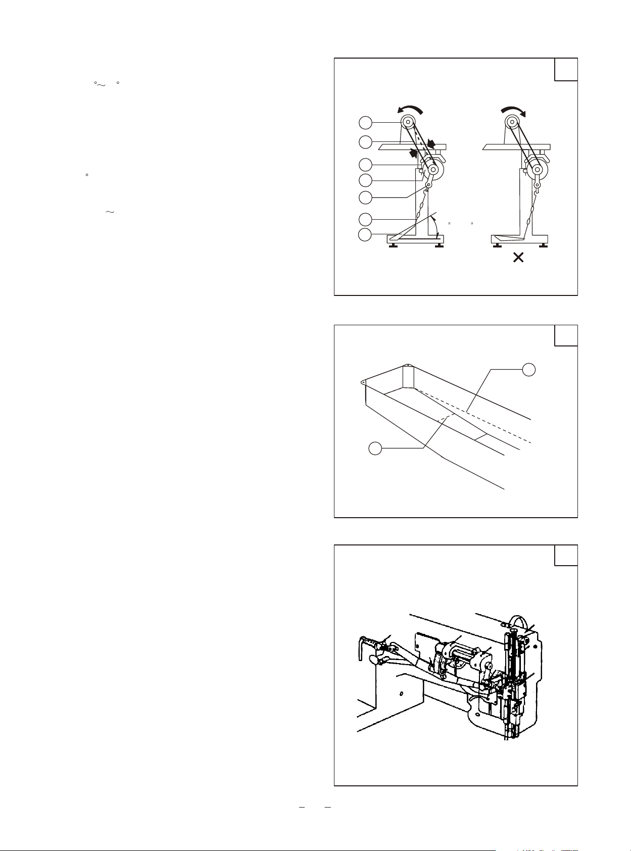
1.4 Install the presser foot lifting controller (Fig. 3)
First connect the chain B with presser foot lift lever
C by hooks A, then install the pedal assembly D on
the rung of the stand, move the controller E leftward
or rightward to make the chain in one line, fix it
with bolt and nut, finally connect the hook with the
controller E.
(An automatic presser foot lifter is also available,
please refer to parts manual Part 7. "Knee lifter and
winding components") . .
A
4
5
1.5 Install the thread stand (Fig. 4)
The thread stand should be located on the right
backside of the table. Threading should be smooth
when sewing. When the machine head is turned
backward, it should not be touched with the thread
stand, then tighten the nut A. .
1.6 Install the motor (Fig. 5)
Move the motor C leftward or rightward to make the
hand wheel belt groove A and motor pulley belt
groove B run in line. .
A
B
C
Page 6
1.7 Connecting the clutch lever to the pedal (Fig. 6)
A. The optimum tilt angle of pedal against floor is
approx. 20 30 . .
B. Adjust the clutch of motor so that the clutch lever
C and draw bar B run in line. .
C. The machine hand wheel should rotate
counter-clockwise for normal sewing when view
from opposite side of balance wheel. The motor
should rotate in the same direction. The rotation can
be reversed by reversing the plug of motor (turn
over 180 ) .
D. Adjust the tension of V-belt F by moving the
motor up and down. The proper tension of V-belt is
a slack of 10 12mm when the belt is depressed at
the belt span by finger. .
G
F
E
D
C
B
A
6
10~12mm
20 ~30
2. Operation preparation and notice before running
2.1 Clearing the machine
Before the head is packed, all of the parts of the
machine are coated with anti-rust grease, meanwhile
the grease can harden and the dust can cover the
machine, surface during long time storage and
shipment, so, the dust and grease must be cleared by
clean cloth with gasoline. .
2.2 Examination
Although every machine is conformed by strict
inspection and test before delivery, the parts of the
machine may be loose and deformed after long
distance transportation with jolt. A thorough
examination must be performed. Turn the balance
wheel slightly by hand to check if there is running
obstruction, parts collision, uneven resistance and
abnormal noise. If any of these exist, adjustment
must be made accordingly before running. .
2.3 Notice before running
A. Oiling (Fig. 7)
Oil amount should be filled according to the marks
in the oil pan, Mark A refers to the highest of oil
amount; Mark B refers to the lowest, be careful that
the oil amount should not be lower than Mark B,
otherwise the machine parts can not be fed with oil
and cause overheat and collision. .
Please be sure to use machine oil 18# or HJ-7.
7
A
B
8
3
Page 7
Oil screen
9
10
B. When the machine starts for initial time or reuse
after a long time, the proper oil amount should be filled
in the sections of machine shown by arrows in Fig. 8,9.
When it is in operation, please observe the oil sparking
in oil screen to check the oil condition. .
C. When a new machine starts running, for extending its
lift, please run at a medium and low speed (1000s.p.m)
for about a month and then raise the speed gradually. .
D. Please turn off the power when it is not in use or the
operator leaves away from it.
E. Replace the oil every month, when replacing, fully
drain off the old oil in the oil pan and add the new one.
F. For 5400TW, the needle gauge options are: 6.4,
3.2,4,4.8,8,9.5,12.7,16,19,24.5mm. To get it, the needle
plate, inner and outer presser foot, needle holder, feed
dog, left and right sliding plate, thread guide should be
changed, the standard needle gauge is 6.4mm, for the
other needle gauge, the relevant parts can be ordered
from the factory. .
.
A
Clearance
Single
needle
Long groove leftward
11
1. Coordination among needle, thread and materials
Please use needle DP 17 or 135 17, Nm125 180, the
coarseness of needle should be in accordance with the
nature of materials. If stitching on heavy weight
materials with a slim needle, the needle will be broken
easily. Needle skipping or thread breakage will also
occur. On the contrary, stitch on tightly materials with a
very coarse needle, the materials will be destroyed
because of over-big needle hole, so the needle and
thread should be properly selected. .
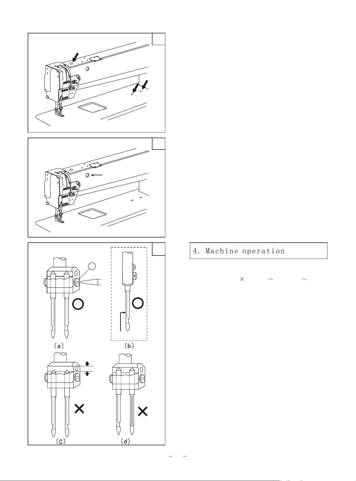
2. Install the needle (Fig. 11)
Turn the hand wheel to lift the needle bar to its highest
position, loosen the needle set screw A, fully insert the
needle shank up to the bottom of needle holder, keep the
long grooves of the two needles opposite with each
other, then tighten the set screw as shown in Fig.(a), For
single needle, keep the long groove of needle facing the
left of the operator as shown in Fig.(b).
Note: Fig.(c) insufficient insertion or Fig. (D) wrong
direction of needle groove is incorrect.
.
.
4
Page 8
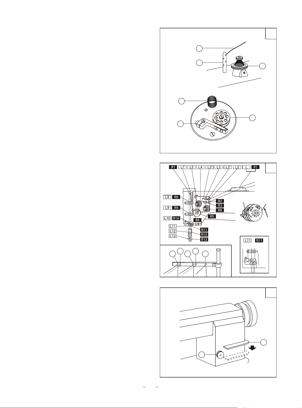
3. Winding the bobbin thread
3.1 The method of winding
Insert the bobbin B into winder shaft, threading the
thread A to upper and lower holes of pin E, then to
thread tension disc F, draw the thread tip and wind
thread several circles around bobbin B, put the
winding lever D into bobbin B, then it can automatic
winding when sewing. (If only winding, not sewing,
please lift the presser foot.)
Please don't overfill the bobbin thread, otherwise the
thread will loosen down from the bobbin. The
optimum capacity of bobbin thread is fill about 80%
of bobbin outside diameter, and this can be adjusted
by screw D. After finish, thread can be cut by thread
cutter shown in Fig. 12. Wind the thread A several
circles around cutter C, draw the thread and the
thread is cut.
.
12
A
E
C
.
D
F
B
3.2 Threading (Fig. 13)
A. Every thread should be drawn through thread hole
A, when using light and smooth thread (polyester or
long silk thread), it should be drawn through thread
hole B.
B. Keep the thread take-up lever at its highest
position, threading the needle thread in the following
numerical order.
3.3 Stitch length (Fig.14)
The stitch length can be regulated by stitch length
dial A. Turn it counter-clockwise to expand its
length and clockwise to shorten its length. The
numbers on dial show the sizes of the stitch length in
mm.
For reverse feed, press down feed lever B to perform
reverse sewing. Release the lever, the feed lever can
reset automatic and the forward sewing is resumed.
.
.
.
.
13
Detailed picture
Thread
B
A
B
A
A
14
B
A
5
Page 9
Sliding plate
Thread
Hook
15
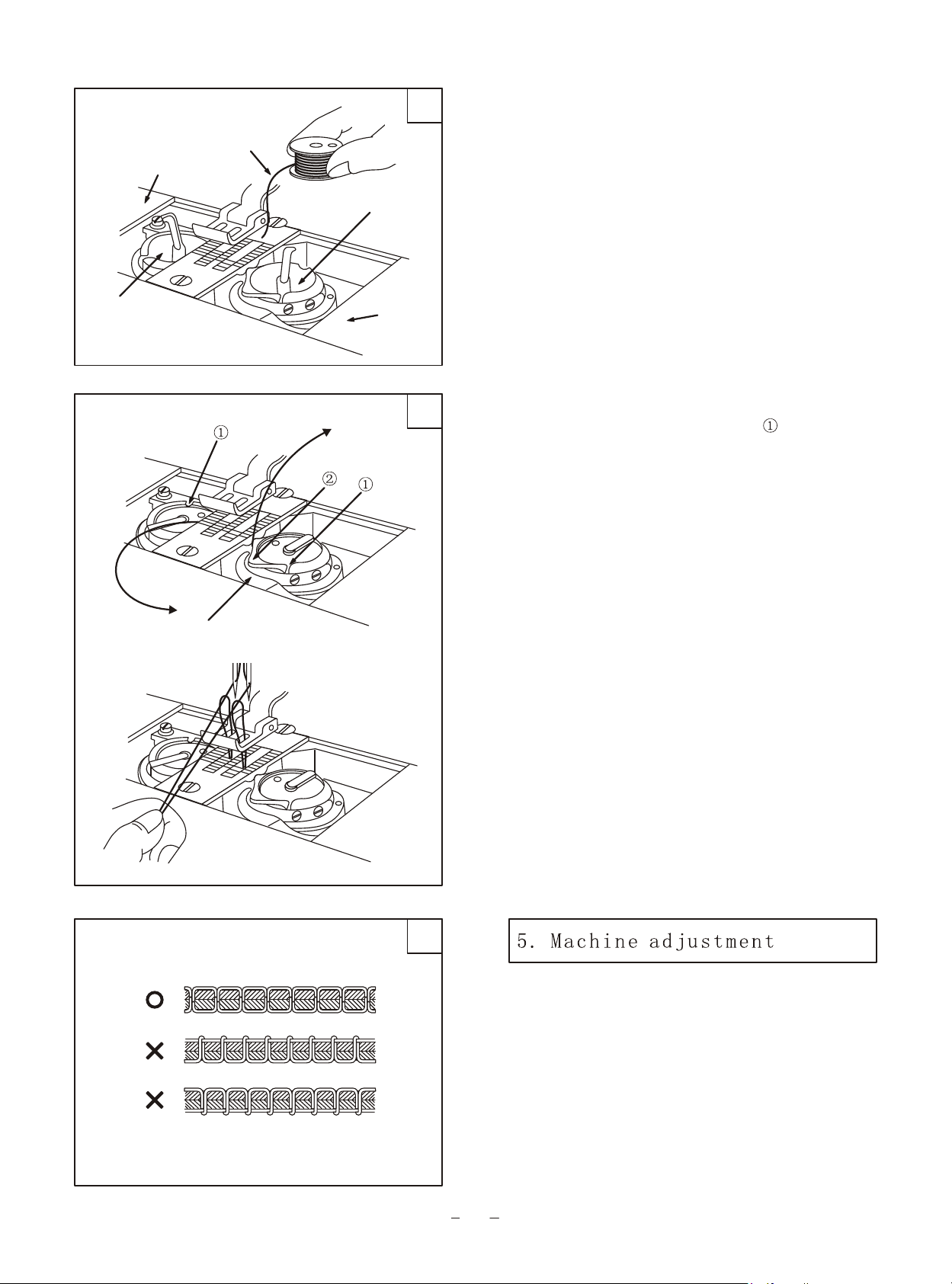
3.4 Placing bobbin (Fig. 15)
Note: when bobbin is placed into the bobbin case, the
thread should be wound properly in the correct direction
shown in the figure. .
Hook
Thread
Inner stop piece
Sliding plate
Thread
16
3.5 Drawing thread from the bobbin (Fig. 16)
A. Draw the thread end to bobbin slot shown in the
figure, and pull it out down through the inner bobbin
stop piece.
B. Hold the thread end with left hand, turn the hand
wheel slowly and get the bobbin thread, then draw them
a little apart from the presser foot.
.
.
A
B
C
Normal stitch seam
Needle thread too tight or bobbin thread too loose
Needle thread too loose or bobbin thread too tight
17
1. Adjust the needle thread tension and bobbin
thread tension
All forms of stitches are shown in Fig. 20
The normal stitch of sewing machine is shown in Fig.
17A. If stitch is abnormal, the puckering and thread
breakage will occur, the needle thread tension and
bobbin thread tension should be adjusted so that the
normal stitch can be obtained. .
6
Page 10
A. If the stitch seam shows as Fig. 17B, indicates
that the needle thread tension is too tight or the
bobbin thread tension is too loose. Please turn the
thread tension nut counter-clockwise to release the
needle thread pressure; or turn the bobbin lace
adjusting screw with a screwdriver to increase the
18
Loosen
bobbin thread tension.( See Fig. 18,19)
B. If the needle thread tension is too loose or the
bobbin thread tension is too tight shown as Fig. 17C.
Please turn the thread tension nut clockwise to
increase the needle thread pressure; or turn the
bobbin lace adjusting screw with a screwdriver to
decrease the bobbin thread tension. (See Fig. 18,19)
For special sewing with special thread, the tension
needed can be obtained by adjusting the power and
stroke of the thread take-up spring.
2. Adjust the pressure of presser foot (Fig.20)
The pressure of presser foot should be adjusted
according to the thickness of the sewing materials. If
stitch on heavy weight materials, the pressure should
be increased by turning the pressure adjusting screw
on the back of machine head clockwise, on the
contrary, turn it counter-clockwise. .
.
Adjusting screw
Tighten
19
.
Nut
Increase
.
Decrease
20
Increase
Decrease
Pressure adjusting
screw
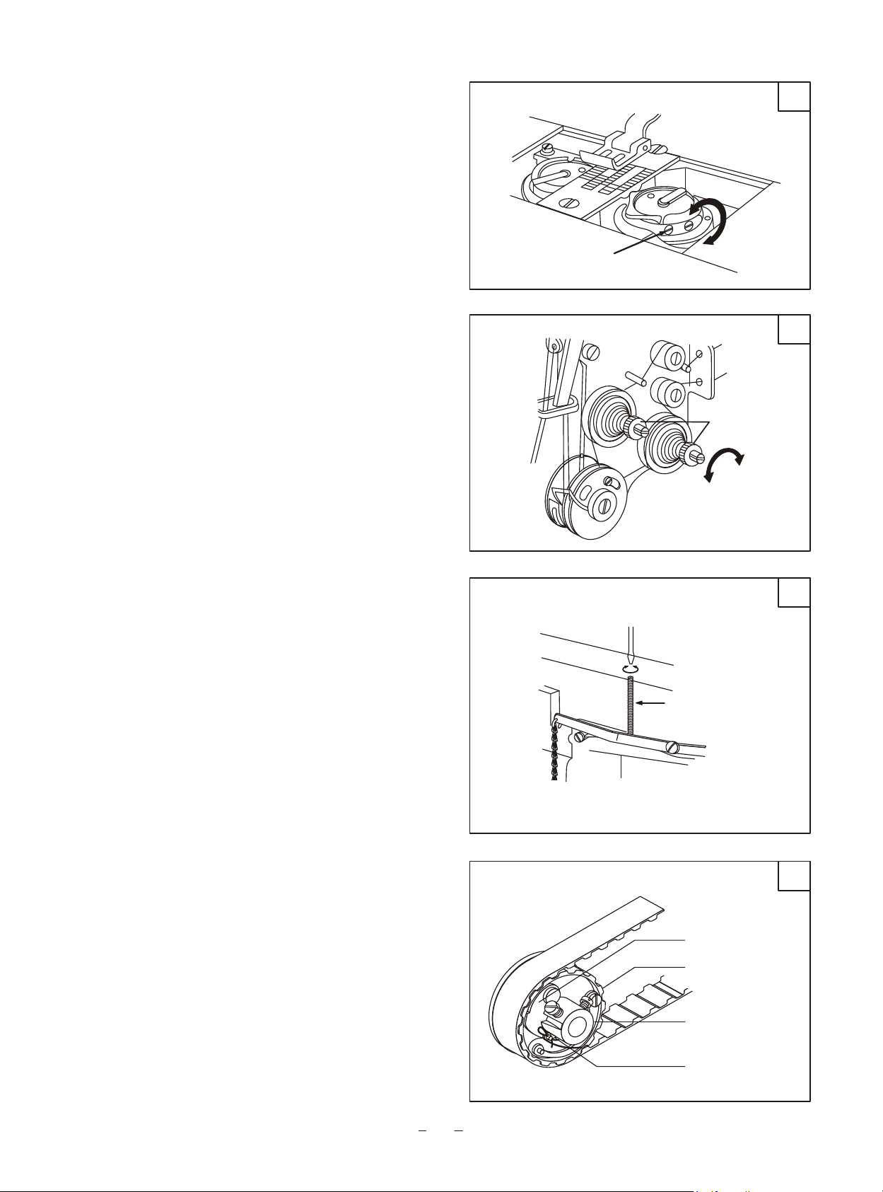
3. Adjust the safety clutch device
The function of safety clutch device is to prevent the
hook and toothed belt from being damaged when the
needle thread is drawn into the hook for abnormal
load during the operation. .
3.1 The function of safety clutch device (Fig.21)
A. When the safety clutch is functioning, the toothed
belt will remove the load and the hook shaft will stop
rotating, only the upper shaft still rotates, and the
machine stops work.
B. Clean off the needle thread which is draw into the
hook.
C. Turn the toothed belt shaft by hand to check if the
hook shaft can turn smoothly, then reset the safety
clutch device.
.
.
.
21
Safety clutch device
Toothed-belt pulley
Shaft
Stopper
7
Page 11
Button
22
Handwheel
3.2 How to reset the safety clutch device (Fig.22)
A. While press down the button on the bed surface with
left hand, turn the hand wheel slowly with right hand in
the direction shown in Fig. 22 (clockwise).
B. When the stopper brakes the hand wheel, more
strength is needed to turn the balance wheel to reset the
safety clutch device.
C. Release the button.
D. So the resetting is OK and put the bobbin into hook.
(See Fig.15)
.
.
.
.
White mark
Tighten
Loosen
Lower shaft
Set screw
Link
Reference line
Special stud
Eccentric pin
Horizontal shaft crank (right)
23
Belt
24
Upper layer feed decreaseUpper layer feed decreaseUpper layer feed decrease
Upper layer feed increaseUpper layer feed increaseUpper layer feed increase
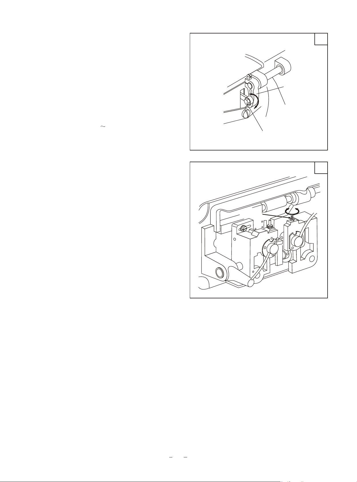
3.3 How to adjust the strength on the safety clutch
device (Fig.23)
A. When the white mark of the eccentric pin aims at the
centre of the lower shaft, indicates that the strength on
the safety clutch is the minimum. When the white mark
points outward, the strength is properly increased.
B. For adjusting the strength of it, move the belt and
loosen the set screw of eccentric pin, and turn the
eccentric pin.
C. After adjustment, please tighten the set screw.
3.4 Adjust the upper feed mechanism (Fig.23)
If the upper and lower feed are not in timing during
sewing, the long hole of the horizontal feed crank(right)
should be adjusted to get the length of upper feed.
Adjusting as follows:
A. Loosen the special stud.
B. Move the stud upward to decrease the amount of
upper feed.
C. Move the stud downward to increase the amount of
upper feed. Theoretically, when it is on the reference
line of the horizontal feed crank, the upper feed amount
equals to the lower feed amount.
D. After adjustment, tighten the special stud.
.
.
.
.
.
.
.
.
.
8
Page 12
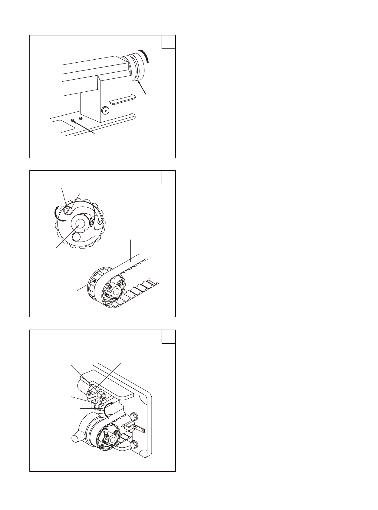
3.5 Adjust the vertical stroke of presser foot (Fig. 25)
When stitch on the very elastic materials or the
thickness of sewing materials changes, the
adjustment should be done in the following order: .
A. Loosen the special stud.
B. When the central line distance between the special
stud and the presser foot lifting rear crank becomes
shorter, the vertical stroke of presser foot will
become longer, on the contrary, the distance becomes
longer, the stroke will become shorter.
C. After adjustment, tighten the special stud. The
common vertical stroke of presser foot can be
adjusted within the range of 2 6mm.
.
25
.
Increase Increase Increase
DecreaseDecreaseDecrease
.
Special stud
Crank
Crank link
3.6 Adjust the hook oil amount (Fig. 26)
It adopts plunger full auto-lubricating system, even
at a very low speed, it still can supply and suck oil
very well. Generally, only the hook oil amount can
be adjusted, the others cannot be adjusted. The hook
oil amount can be controlled by the oil amount
adjusting screw. First loosen the nut of adjusting
screw, turn the screw clockwise to increase the oil
amount, on the contrary, decrease the oil amount.
After adjustment, tighten the nut. .
Oil amount
Oil amount
Oil amount
adjusting screw
adjusting screw
adjusting screw
Increase Increase Increase
26
Decrease
9
Page 13

Parts manual
Page 14

1.
5400TW
machine casting components
12
11
67
9
10
68
12
13
13
48
45
47
44
64
63
45
55
46
14
58
49
62
60
61
57
7
2
8
1
6
14
4
5
3
50
51
52
53
54
56
59
41
42
43
17
18
28
34
33
32
37
31
30
40
29
19
23
66
22
27
65
20
21
36
26
35
15
16
38
24
25
39
10
Page 15

1.
5400TW machine casting components
No .
1
2
3
4
5
6
7
8
9
10
11
12
13
14
15
16
17
18
19
20
21
22
23
24
25
26
27
28
29
30
31
32
33
34
35
36
37
38
39
40
41
42
43
Part number
43WF1-001
43WF1-002
43WF1-003B
43WF1-004B
1WF1-015
1WF1-016
1WF1-017
1WF1-011
22T1-007
1WF1-032
1WF1-038
1WF1-039
1WF1-019
1WF1-030
1WF1-027
1WF1-028
1WF1-003
1WF1-004
1WF1-005
1WF1-034
1WF1-036
1WF1-007
1WF1-006
1WF1-018
1WF1-013
1WF1-009
1WF1-008
1WF1-012
1WF1-021
1WF1-020
1WF1-035
1WF1-037
1WF1-023
1WF1-033
1WF1-040
1WF1-029
1WF1-022
1WF1-031
1WF1-014
Name
Machine bed
Machine arm
Pin
Screw
Screw
Model label
Brand label
Rivet
Upper thread guide
Screw
Back cover
Screw
Washer
Cover
Front slide plate
Screw
Thread take-up lever cover
Back front cover
Screw
Spring
Thread retainer
Lower thread finger
Screw
Screw
Screw
Screw
Middle thread finger
Rubber plug
Face plaft
Screw
Upper thread finger
Guide set plate
Oil stopper set plate
Oil stopper
Needle plate
Pin shaft
Thread releasing lever
Right sliding plate
Left sliding plate
Rubber plug 14.5
Rubber plug 12.7
Back fitting cover
Rubber plug 12.7
8.5
Qt.
1
1
2
1
3
1
1
4
1
2
1
15
15
2
1
1
1
1
1
1
1
1
1
1
1
1
1
2
1
2
1
1
1
1
1
1
1
1
1
1
1
1
1
Remark
A6 30 GB117-86
M10 35 GB70-85
M10 35 GB5781-85
2.5 5 GB827-86
SM11/64" 40/8
SM11/64" 40/9
PE
SM11/64" 32/5.4
SM9/64" 40/6.5
SM11/64" 40
SM9/64" 40
SM3/16" 28
11
Page 16

1.
5400TW m
achine casting components
12
11
67
9
10
68
12
13
13
48
45
47
44
64
63
45
55
46
14
58
49
62
60
61
57
7
2
8
1
6
14
4
5
3
50
51
52
53
54
56
59
41
42
43
17
18
28
34
33
32
37
31
30
40
29
19
23
66
22
27
65
20
21
36
26
35
15
16
38
24
25
39
12
Page 17

1.
5400TW machine casting components
No .
44
45
46
47
48
49
50
51
52
53
54
55
56
57
58
59
60
61
62
63
64
65
66
67
68
Part number
1WF1-010A
1WF1-010B
1WF1-010C
1WF1-010D
1WF1-010E
1WF1-010M
1WF1-010H
1WF1-010G
1WF1-010S
1WF1-010F
1WF1-010R
1WF1-010Q
1WF1-010J
1WF1-026
1WF1-025
1WF1-010K
1WF1-010I
1WF1-024
1WF1-010L
1WF1-010W
1WF1-010P
1WF1-043
22T2-004
43WF1-006
35WF1-006
Name
Thread tension fixing bracket assembly
Thread guide bracket
Thread guide plate
Spring
Thread guide b acket screw assembly
Thread releasing pin (short)
Thread tension nut
Thread tension spring
Thread releasing disc
Thread tension disc
Screw
Screw
Thread controlling disc assembly
Screw
Stop plate
Thread take-up spring
Thread take-up spring shaft
Screw
Thread releasing pin (long)
Thread tension retaining plate
Thread releasing spring
Spring retaining plate
Screw
Rubber plug
Thread guide pin
r
1
2
2
2
2
1
3
2
2
4
1
2
2
1
1
1
1
1
1
1
1
1
1
1
1
Qt.
Remark
SM9/64" 40/4.5
SM/64" 40/4.5
13
Page 18

2.
5400SW m
achine casting components
12
11
64
9
10
65
12
13
13
46
43
45
42
62
61
43
53
44
14
56
47
60
58
59
55
7
2
8
1
6
14
4
5
3
48
49
50
51
52
54
57
39
40
41
17
18
26
32
31
30
35
29
28
38
27
21
20
63
25
34
19
24
33
15
16
36
22
23
37
14
Page 19

2.
5400
SW ma
chine casting components
No .
1
2
3
4
5
6
7
8
9
10
11
12
13
14
15
16
17
18
19
20
21
22
23
24
25
26
27
28
29
30
31
32
33
34
35
36
37
38
39
40
41
Part number
44WF1-003
43WF1-002
44WF1-002
44WF1-005
1WF1-015
1WF1-016
1WF1-017
1WF1-011
22T1-007
1WF1-032
1WF1-038
1WF1-039
1WF1-019
1WF1-030
1WF1-005
9WF1-001
9WF1-002
1WF1-034
1WF1-036
1WF1-007
1WF1-006
1WF1-018
1WF1-013
1WF1-009
1WF1-008
1WF1-012
1WF1-021
1WF1-020
9WF1-004A
1WF1-043
1WF1-023
1WF1-033
1WF1-040
1WF1-029
1WF1-022
1WF1-031
1WF1-034
Name
Machine bed
Machine arm
Pin
Screw
Screw
Model label
Brand label
Rivet
Upper thread guide
Screw
Back cover
Screw
Washer
Cover
Front slide plate
Screw
Thread take-up lever cover
Back front cover
Screw
Lower thread finger
Oil felt
Screw
Screw
Screw
middle thread finger
Rubber plug
Face plate
Screw
Upper thread finger
Guide set plate
Oil stopper set plate
Oil stopper
Needle plate
Right sliding plate spring retainer
Thread releasing lever
Right sliding plate
Left sliding plate
Rubber plug
Rubber plug
Back fitting cover
Rubber plug 12.7
8.5
14.5
12.7
Qt.
1
1
2
1
3
1
1
4
1
2
1
15
15
2
1
1
1
1
1
1
1
1
1
1
1
1
1
2
1
1
1
1
1
1
1
1
1
1
1
1
1
Remark
A6 30 GB117-86
M10 35 GB70-85
M10 35 GB5781-85
2.5 5 GB827-86
SM11/64" 40/8
SM11/64" 40/9
PE
SM11/64" 32/5.4
SM3/16" 28
15
Page 20

2.
5400SW machine
casting components
12
11
64
9
10
65
12
13
13
46
43
45
42
62
61
43
53
44
14
56
47
60
58
59
55
7
2
8
1
6
14
4
5
3
48
49
50
51
52
54
57
39
40
41
17
18
26
32
31
30
35
29
28
38
27
21
20
63
25
34
19
24
33
15
16
36
22
23
37
16
Page 21

2.
5400SW ma
chine casting components
No .
42
43
44
45
46
47
48
49
50
51
52
53
54
55
56
57
58
59
60
61
62
63
64
65
Part number
1WF1-010A
1WF1-010B
1WF1-010C
1WF1-010D
1WF1-010E
1WF1-010M
1WF1-010H
1WF1-010G
1WF1-010S
1WF1-010F
1WF1-010R
1WF1-010Q
1WF1-010J
1WF1-026
1WF1-025
1WF1-010K
1WF1-003A
1WF1-024
1WF1-010I
1WF1-010W
1WF1-010P
22T2-004
43WF1-006
35WF1-006
Name
Thread tension fixing bracket assembly
Thread guide bracket
Thread guide plate
Spring
Thread guide bracket screw assembly
Thread releasing pin (short)
Thread tension nut
Thread tension spring
Thread releasing disc
Thread tension disc
Screw
Screw
Thread controlling disc assembly
Screw
Stop plate
Thread take-up spring
Thread take-up spring shaft
Screw
Thread releasing pin (long)
Thread tension retaining plate
Thread releasing spring
Screw
Rubber plug
Thread guide pin
Qt.
1
1
1
1
1
1
1
1
1
2
1
2
1
1
1
1
1
1
1
1
1
1
1
1
Remark
SM9/64" 40/4.5
SM/64" 40/4.5
17
Page 22

18
46
49
45
44
48
51
47
50
41 42
6
12
33
131415 16
54
8
55
14
56
13
53
32
20
52
29
31
21
22
30
17
19
23
24
25
26
27
28
36
35 37 3839 40
4
2
1
34
11
10
43
7
3
5
8
9
18
Page 23

No .
Part number
Name
Qt.
Remark
1
2
3
4
5
6
7
8
9
10
11
12
13
14
15
16
17
18
19
20
21
22
23
24
25
26
27
28
29
30
31
32
33
34
35
36
37
38
39
40
41
42
43
44
45
46
47
48
49
50
51
52
53
54
55
56
43WF2-001
1WF2-022
1WF2-023
1WF2-024
1WF2-021
1WF2-020
1WF2-007
1WF2-010
1WF2-009
1WF5-026
1WF5-041
1WF2-026
1WF2-030
1WF2-029
1WF2-031
1WF2-019
1WF2-032
1WF2-044
1WF2-028
1WF2-039
1WF2-037
1WF2-041
1WF2-040
1WF2-048
1WF2-045
1WF2-042
1WF2-046
1WF2-047
1WF2-038
1WF5-001
1WF5-025
1WF5-044
1WF5-023
1WF5-024
1WF5-045
1WF4-018
1WF5-038
1WF5-028
1WF5-037
1WF5-030
1WF5-029
1WF5-032
1WF5-033
1WF5-034
1WF5-035
1WF5-042
1WF2-027
1WF2-037
43WF3-004
JO.0.40
43WF2-003
Upper shaft
Upper shaft bushing (front)
Screw
Oil felt
Needle crank
Screw
Screw
Screw
Screw
Eccentric cam
Stop ring
Slot for front crank sliding block
Stop ring
Screw
Screw
Ball bearing
Upper shaft bushing (rear)
Screw
Hand wheel
Screw
Toothed belt
Spring plate
Pin
Spring
Split stop ring
Stop plate
Nail
Braking plate
Connector
Bushing
Screw
Screw
Nut
Link lever
Bolt
Washer
Oil pipe assembly
Spring
Presser foot lifting crank (rear)
Screw
Presser foot lifting c ank (front)
Screw
Bushing
Link lever
Screw
Screw
Presser foot lifting movable plate
Rolling ball shaft
Rolling ball
Washer
Screw
Upper shaft timing pulley
Lower shaft timing pulley
Bobbin winding shaft
Screw
Upper shaft bushing (middle)
r
1
1
1
1
1
1
1
3
1
1
1
1
3
3
1
1
1
2
1
2
1
1
1
1
1
1
1
1
1
1
1
1
1
1
1
1
1
1
1
3
1
2
2
1
1
1
1
1
1
2
2
1
1
1
2
1
SM1/4" 24/13
Wool felt
SM9/32"/28
SM1/4" 40/7
SM1/4" 40/4
25 GB894.1-86
SM15/64" 28/8.5
SM15/64" 28/15
SM15/64" 28/12
SM15/64" 28/4.5
3 GB896-86
SM15/64" 28/10.5
SM15/64" 28/10
Washer 6 GB95-85
SM1/4" 24/16
SM1/4" 24/8
SM11/64" 40/6
Washer 4 GB848-85
SM11/64" 40/10
19
Page 24

30
29
28
1 2
3
5 6
4
7
8 9 10
12
13
27
26
25
24
32
31
22
23
75 76
74
73
5400TW
70
72
33
34
35
14
15
16
17
18
19
20
21
36
37
5400SW
33
35
6869
11
383940
34
41
59
424344
61
43 45
5960
464748 49
42
63
1
5253
77
78
79
71
51
50
80
58
64 656667
62
45565754
54555657
45
20
Page 25

No .
Part number
Name
Qt.
Remark
1
2
3
4
5
6
7
8
9
10
11
12
13
14
15
16
17
18
19
20
21
22
23
24
25
26
27
28
29
30
31
32
33
34
35
36
37
38
39
40
1WF5-017
1WF5-018
1WF5-031
1WF5-019
1WF2-018
1WF2-017
1WF2-016
1WF2-011
1WF2-019
1WF2-012
1WF2-013
1WF2-014
1WF2-015
1WF2-008
1WF5-011
1WF5-013
1WF5-012
1WF2-007
1WF2-005
1WF2-006
1WF2-004
1WF2-001
1WF2-006
1WF5-010
22T1-007
1WF5-009
1WF5-036
1WF3-009
1WF5-014
1WF5-016
1WF5-015
1WF5-043
35T5-502
22T2-004
1WF2-003
35T1-103
1WF2-002
22T2-017
1F-009
1WF5-007
1WF5-008
1WF5-020
1WF5-021
Oil wick
Shaft for needle bar rocking frame
Screw
Screw
Oil wick
Bushing
Thread take-up lever
Thread take-up lever sliding block
Screw
Oil wick
Plug
Needle bar crank pin
Oil wick
Needle bar link
Needle bar rocking frame
Screw
Shim needle bar rocking frame
Oil felt
Needle bar connector
Screw
Needle bar
Needle bar
rocking pressing bar
Screw
Washer
Needle bar holder guide
Pressing bar link
Screw
Guiding plate
Spring
Spring bar
Inner presser foot
Inner presser foot
Screw
Needle holder
Needle bar thread guide
Needle holder screw
Needle set screw
Needle
Needle bar rocking sliding block
Sliding block shaft
Needle bar rocking left crank
Pin
Washer
2
1
1
1
1
1
1
1
1
1
1
1
1
1
1
6
2
1
1
1
1
1
1
1
1
1
1
2
1
1
1
1
1
1
1
1
2
1
2
1
1
1
1
1
2.5 80
SM5/16" 28/10
SM15/64" 28/8
2.5 240
SM15/64" 28/12
325
3 80 cotton thread
SM3/32" 56/4.6
SM9/64" 40/8.5
400TW
5
5400SW
SM11/64" 40/12
Washer GB848-85
SM11/64" 40/15
MSK-8420BL-18
MSK-8400BL-18
MSK-8420BL-18
MSK-8400BL-18
SM9/64" 40/4.3
MSK-8400BL-L18
DP 17 23#
A4 24 GB117-86
cotton thread
cotton thread
21
Page 26

30
29
28
1 2
3
5 6
4
7
8 9 10
12
13
27
26
25
24
32
31
22
23
75 76
74
73
5400TW
70
72
33
34
35
14
15
16
17
18
19
20
21
36
37
5400SW
33
35
6869
11
383940
34
41
59
424344
61
43 45
5960
464748 49
42
63
1
5253
77
78
79
71
51
50
80
58
64 656667
62
45565754
54555657
45
22
Page 27

No .
Part number
Name
Qt.
Remark
41
42
43
44
45
46
47
48
49
50
51
52
53
54
55
56
57
58
59
60
61
62
63
64
65
66
67
68
69
70
71
72
73
74
75
76
77
78
79
80
1WF5-022
1WF5-027
1WF5-028
43WF5-001
1WF4-018
1WF5-005
1WF5-004
1WF5-003
1WF5-049
1WF5-002
1WF5-046
1WF5-047
1WF5-001
1WF4-052
1WF2-023
1WF4-054
1WF2-009
1WF4-017
1WF4-019
1WF4-020
43WF4-001
1WF4-038
1WF4-035
1WF4-034
1WF4-030
1WF4-029
1WF4-036
1WF4-031
1WF4-001
9WF4-001
1WF4-032
1WF4-005
1WF4-004
9WF4-002A
1WF4-007
1WF4-008
1WF4-009
1WF4-002
1WF4-003
1WF4-033
Screw
Bushing
Screw
Needle bar rocking shaft
Screw
Rear crank
Nut
Link lever
Screw
Feed shaft right crank
Pin
Washer
Nut
Feed shaft bushing
Screw
Collar
Screw
Feed crank
Split stop ring
Crank pin
Oil wick
Feed shaft
Oil felt
Connecting crank (left)
Screw
Oil wick
Oil wick clamp
Crank shaft
Oil wick
Feed dog support
Feed dog support
Screw
Washer
Screw
Feed dog
Feed dog
Screw
Oil felt
Feed dog lifting fork
Nut
Screw
Screw
2
2
2
1
3
1
1
1
1
1
1
1
1
2
2
2
4
1
2
1
1
1
2
1
2
1
1
1
1
1
1
1
1
2
1
1
1
1
1
1
1
1
SM1/4" 24/8
SM1/4" 40/4
Stop ring 5 GB896-86
3 55 cotton thread
Wool felt
SM3/16" 28/12
2.5 430 cotton thread
5400
TW
5400SW
M15/64" 28/16
S
Washer 6 GB95-85
SM1/8" 40/7
5400TW
5400SW
SM1/8" 44/4 Wool
felt
SM1/8" 40/13.5
SM11/64" 40/6
23
Page 28

28
27
7
8
6
5
4
3
2
9
10
11
12
13
14
15
16
17
18
29
28
25
31 32 33 34 35 36 37
26
40
39
38
41
24
42
19
20
23
1
43
44
22
45 46
47
21
484950 51 52
24
53
30
54
Page 29

No .
Part number
Name
Qt.
Remark
1
2
3
4
5
6
7
8
9
10
11
12
13
14
15
16
17
18
19
20
21
22
23
24
25
26
27
28
29
30
31
32
33
34
35
36
37
38
39
40
41
42
43
44
45
46
47
48
49
50
51
52
53
54
1WF2-063
1WF2-060
1WF2-059
1WF2-061
1WF2-064
1WF2-065
1WF2-070
1WF2-069
1WF2-072
1WF2-071
1WF2-075
1WF2-026
1WF2-076
1WF2-074
1WF2-062
1WF2-034
1WF2-033
1WF2-077
1WF2-067
1WF2-066
1WF2-044
1WF2-068
1WF2-052
1WF2-078
1WF2-009
1WF2-079
1WF2-055
1WF2-035
1WF2-036
43WF2-002
1WF2-006
1WF2-019
43WF2-004
1WF2-058
1WF4-041
1WF4-042
1WF4-010
1WF4-011
1WF4-012
1WF2-055
1WF2-051
1WF2-009
1WF2-052
1WF2-050
1WF2-049
1WF4-044
1WF4-043
Right hook saddle
Screw
Upper bushing
Lower bushing
Rotary hook assembly
Bobbin
Oil wick
Hinge shaft
Screw
Link lever
Inner hook finger bracket
Screw
Washer
Inner hook finger
Washer
Nut
Upper bushing
Screw
Washer
Screw
Lower bushing
Nut
Screw
Screw
Left hook saddle
Screw
Spiral gear
Screw
Spiral gaer
Feed link
Lower shaft bushing (left)
Oil wick
Lower shaft
Feed dog lifting cam
Screw
Lower shaft bushing (right)
Oil wick
Stop ring
Spring
Button
Screw
Feed cam
Feed link
Needle bearing
Stop ring
Lower shaft bushing assembly (middle)
Lower shaft bushing (rear)
Screw
Screw
Bearing
Bearing pressing ring
Screw
Oil wick
Pin
SM14/64" 28
2.5 14 cotton thread
SM3/16" 32
SM9/64" 40/4.5
Washer 4 GB848-85
Washer 4 GB848-85
SM3/16" 32
SM3/16" 28/14.5
Stop ring
SM1/4" 24/20
SM3/16" 28
SM3/16" 28/25.5
SM1/4" 40/5
SM1/4" 40/4
25 45
SM15/64" 28/12
2.5 85 cotton thread
Stop ring 5 GB896-86
SM15/64" 28/13.5
Stop ring
SM1/4" 40/4
SM1/4" 40/5
SM9/64" 40/7
6 GB95-85
cotton thread
26 GB894.1-86
Note: the figure in the bracket is the parts quantity of 5400SW
25
Page 30

3
2
1
4
5 6
16
15
12
18
8
19
10
7
2
9
13
14
28
11
29
30
27
24
24
2526
17
20
23
2
2122
26
Page 31

No .
Part number
Name
Qt.
Remark
1
2
3
4
5
6
7
8
9
10
11
12
13
14
15
16
1WF4-025
1WF4-030
1WF4-026
1WF4-014
1WF4-028
1WF4-046
1WF4-047
1WF4-027
1WF4-021
1WF4-048
1WF4-040
1WF4-049
1WF4-050
1WF4-051
1WF4-024
1WF5-006C3
Stitch length adjusting rocking lever
Screw
Set screw
Stitch length link
Eccentric shaft
Reverse feed shaft
Reverse feed crank
Screw
Screw
Reverse feed lever
Sliding block
Crank spring
Spring bracket
Screw
Stop pin
Spring
1
SM15/64" 28/8.5
5
SM15/64" 28/12
1
1
1
1
1
SM15/64" 28/13
1
SM15/64" 40/10.5
1
1
2
1
1
SM11/64" 40/8
1
1
1
17
18
19
20
21
22
23
24
25
26
27
28
29
30
43WF4-002
1WF4-022
1WF5-009
1WF4-013
1WF4-015
1WF2-038
1WF4-016
1WF4-053
1WF4-057
1WF4-045
1WF4-039
1WF4-056
1WF1-011
Screw bar
'O' type seal
Stitch length dial
Screw
Stitch length adjusting crank shaft
Stitch length adjusting crank
Screw
Screw
Collar
Reverse feed adjusting bracket
Oil wick
Oil wick
Guiding plate
Screw
1
44
1 2. GB1235-86
1
1
1
1
1
SM15/64" 28/10
1
SM15/64" 28/6
3
1
1
1
1
2
4
3 26 cotton thread
4 16 cotton thread
SM11/64" 40/9
27
Page 32

23
22
14
19
15
16
17
50
44
49
48
25
24
26
11
28
27
18
2
21
20
29
33
34
12
13
9
10
3637
35
6
7
8
30
31
32
3
4
5
1
52
47
46
45
44
43
42
41
40
39
51
38
Automatic presser foot lifter components
56
55
57
54
59
58
36 53
28
Page 33

No .
Part number
Name
Qt.
Remark
1
2
3
4
5
6
7
8
9
10
11
12
13
14
15
16
17
18
19
20
21
22
23
24
25
26
27
28
29
30
31
32
33
34
35
36
37
38
39
40
41
42
43
44
45
46
47
48
49
50
51
52
53
54
55
56
57
58
59
13WF4-027
13WF6-029
33T4-008C1
22T1-012F5
13WF6-028
13WF6-012
13WF6-014
13WF6-017
13WF6-018
13WF6-019
13WF6-001
13WF6-021
13WF6-022
13WF6-002
13WF6-006
13WF6-007
13WF6-008
13WF6-009
13WF6-010
13WF6-011
13WF6-015
13WF6-016
13WF6-005
13WF6-003
13WF6-004
13WF6-025
33WF6-020
13WF6-013
1WF5-040
1WF5-039
1WF3-011
1WF3-010
1WF3-013
1WF -0
314
43WF3-001
1WF3-012-D
1WF3-015
1WF3-016
1WF3-001
9WF3-001
1WF3-002
1WF3-004
1WF3-005
1WF2-006
1WF3-023
1WF3-022
1WF3-007
1WF3-008
1WF3-009
1WF3-003
1WF3-023
1WF3-006
1WF3-018
1WF3-019-D
1WF3-017-D
43WF3-01-DB
43WF3-01-DA
Screw
Nut
Thread tension spring
Thread tension disc
Thread tension shaft
Crank
Screw
Bobbin winding pulley
Screw
Friction ring
Winder base
Winding crank
Pin
Screw (lower)
Winding spanner
Spring lever
Screw
Screw
Screw
Winding spanner shaft
Stop ring
Winder shaft
Locking ring
Bobbin thread trimmer
Screw (upper)
Spring
Spring
Positioning pin
Positioning pin
Slot for sliding block
Screw
Screw
Nut
Screw
Spring
Knee lifting lever
Knee lifting lever
Screw
Presser bar spring lever
Outer presser foot
Outer presser foot
Screw
Presser bar bushing
Presser bar spring lever bracket
Screw
Presser foot lifting bar
Screw
Thread releasing plate
Presser bar guiding bracket
Screw
Presser bar
Screw
Thread releasing spring lever
Screw
Crank assembly
Screw
Block
Solenoid assembly
Screw
Washer
Washer
1
1
1
2
1
1
1
1
2
1
1
1
1
1
1
1
1
1
1
1
Stop ring 3.5 GB896-86
1
1
1
1
1
1
1
1
1
1
SM1/64" 40/12
2
SM1/4" 24/16.5
1
1
1
1
(For presser foot lifter by pedal)
1
(For automatic presser foot lifter)
1
1
1
1
5400TW
1
5
400SW
1
2
1
SM9/64" 40/8.5
1
1
1
1
1
SM11/64" 40/15
1
1
SM1/4" 24 23
2
1
1
1
1
1
PF-9
1
2
GB93-8
2
GB97.1-8
2
29
Page 34

3
6
4
8910
7
11 12
13
14
39
5
2
464748
1
41
40
42
23
16 202126 20
44
43
45
49
21
24
23
22
25
26
27
28
3435363738
1616 2323
32
33
293031
15
16
17
18
19
20
21
30
Page 35

No .
Part number
Name
Qt.
Remark
1
2
3
4
5
6
7
8
9
10
11
12
13
14
15
16
17
18
19
20
21
22
23
24
25
26
27
28
29
30
31
32
33
34
35
36
37
38
39
40
41
42
43
44
45
46
47
48
49
1WF6-001
1WF6-034
1WF6-003
1WF6-005A
1WF6-004
1WF6-007
1WF6-008
1WF6-009
1WF6-006
1WF6-010
1WF6-011
1WF6-002
1WF6-013
1WF6-012
1WF1-024
1WF6-042
1WF6-014
1WF1-011
22T1-007
1WF6-021
1WF1-026
1WF2-053
1WF2-054
1WF6-027
1WF6-025
1WF6-024
1WF6-023
1WF6-026
1WF6-018
1WF6-019
1WF6-020
1WF6-017
1WF6-028
1WF6-035
636
1WF -0
1WF6-038
1WF6-041
1WF6-040
1WF6-039
1WF6-034
1WF6-032
1WF6-037
1WF6-033
1WF6-030
1WF6-031
1WF6-029
1WF6-015
Oil felt press spring
Screw
Oil felt
Oil pipe
Oil wick
Oil cup
Oil cup cover
Screw
Pin
Oil wick press spring
Oil pipe
Oil draining pipe
Oil wick
Oil pipe positioning clamp
Needle bar oil returning pipe
Screw
Washer
Oil returning pipe clamp
Set spring
Screw
Washer
Oil draining pipe end clamp
Screw
Screw
Bushing
Oil pipe
Plunger
Plunger spring
Plunger spring stopper
Screw
Oil filter
Washer
Filter net
Oil filter fixing plate
Oil pipe clamp
Oil pipe for right hook saddle
Oil pipe clamp
Oil tray assembly
Oil tray assembly
Oil wick
Oil pipe
Oil pipe
Oil pipe clamp
Oil pipe
Oil wick
Oil wick
Clamp
Oil pipe clamp
Oil nozzle assembly
Oil filter fixing bracket
1
1
1
1
1
1
1
2
1
1
1
1
1
1
1
10
1
1
1
4
4
1
8
2
1
2
1
1
1
1
1
1
1
1
1
1
3
2
1
1
1
1
3
2
1
1
1
1
1
1
SM3/16" 28/12
Wool felt
3D 0.5 60
Cotton thread
M4 16 GB69-85
3D 1 400
5D 1 400
2.5 550 cotton thread
3D 0.5 150
SM9/64" 40/9
Washer 4 GB7246-87
SM /64" 40/
11 9
SM /64" 40/
9 4.5
SM 1/ 4"
1 6 40/10
3D190
SM1/8" 44/4.5
H62 brassiness
400TW
5
400SW
5
2.5 430 cotton thread
3D 0.5 410
3D 1 445 MSK-8420BL-( 18)
3D 0.5 220
2.5 300
2.5 240
(MSK-8420BL-18)
(MSK-8420BL-18)
31
Page 36

6
7
1
12
10
11
8
18
9
2
19
3
4
5
16
15
13
14
20
21
22
17
32
Page 37

No .
Part number
Name
Qt.
Remark
1
2
3
4
5
6
7
8
9
10
11
12
13
14
15
16
17
18
19
20
21
22
33TF-010
22T9-007F1
22T9-007F2
22T9-009
22T9-010
1WF2-065
33TF-011
33TF-016
1F-009
1F-011
1F-010
33TF-012
33TF-013
33TF-014
58T0-007C
22T9-018
1F-012
1F-014
33TF-019
22F9-012
22T9-001A2
22T9-001A3
43WF3-002
Parts bag
Casting hinge
Casting hinge cushion
Casting cushion (big)
Casting cushion
Bobbin
Oil pot
V-belt
Needle
Hexagon wrench
Hexagon wrench
Screwdriver (big)
Screwdriver (middle)
Screwdriver (small)
Needle thread guide assembly
Machine head cover
Oil tank
Thread stand
Thread stand
Magnet
Oil draining screw
Was h
Oil pan
1
2
2
2
2
4
1
1
1 bag
1
1
1
1
1
1
1
1
1
1
1
1
1
1
'O' type 1050
DP 17 23#
S=2.5MM
S=3MM
5400TW
5400SW
SM5/16" 25/10
33
Page 38

Page 39

Page 40

1 800 268 1649
www.reliablecorporation.com
 Loading...