

Page 1
MSK-1341B
Industrial Sewing Machine
INSTRUCTION MANUAL
Page 2
1. Br ie f in tr od uc ti on 1. Ma in s pe ci fi ca ti on
T h i s c y l i n d e r b e d s e w i n g m a c h i n e a d o p t s s i n g l e
n e e d l e , s l i d e t y p e t h r e a d t a k e - u p l e v e r , a n d v e r t i c a l l a r g e
h o k . U p p e r a n d l o w e r s h a f t s a r e d r i v e n b y s y n c h r o n i z e d
t o o t h e d b e l t . C o m p o u n d f e e d b y f e e d d o g , n e e d l e a n d
wa lki n g fo ot; and h igh p re s se r f oo t st r ok e an d li fte r as sur e
i t s h i g h s w e i n g h e a v y a b i li ty a n d e a s y f or s e wi ng m u lt il a y e r l e a t h e r a n d u n e v e n m a t e r i a l s . S a f e t y c l u t c h d e v i c e
als o a ssur e s s afe op e ra ti on .
I t s w i d e l y u s e d f o r s e w i n g l e a t h e r p r o d u c t s , s u i t c a s e s ,
s h o e s a d c a p s . E sp e ci a l l y , i t s c y l i n d e r b e d i s s u i t a b l e f or
sew i ng vari o u s ar c a nd curv e d m at eria l s . .
Max . se wi ng spe e d
Max . st it ch len g t h
Nee d le b ar s trok e
Pre s se rf oot li f t
hei g ht
Thr e ad t ak e-up l e v er
Hoo k
Nee d le
Lub r ic at ion
Mot o r Po we r
Abb l ic at ion
MSK-1341 B
2000 s . p . m
6mm
33.3 6 m m
6.5m m b y h a n d
15mm b y k n e e
Slid e t y p e
Larg e h o o k
Dp×1 7 14 " ~ 24 " ( s ta n d ar d 2 3 ")
Oile d b y h a n d
400W ( s p e c i al f o r s e wi n g m ac h i n e 2P )
Medi u m , h e a vy , e x tr a h e av y
weig h t m a t e r ia l s
3. Op er at io n pr ep ar at io n
Bef re f irst o p erat e t he mac h ine, pl ease c l ean th e m achi n e thor o ughl y in o rder t o w eed ou t t he
dus t an d frll y l ubri c ate th e m achi ne .
Ple as e conf i rm if th e p ower w i ll be us ed i s suit a ble fo r t he des i gned v o ltag e.
The r ot atin g d irec t ion of t h e mach in e is cou n ter- c lock w i se whe n o bser ve d face t o t he han d w heel .
Bef or e turn o v er the m a chin e h ead, pl ease t a ke dow n t he kne e l ifte r c hain h oo k.
Bef or e tria l r unni n g,pl e ase ta ke d own th e b obbi n a nd nee d le.
Ple as e cont r ol the s e wing s p eed un de r 1800 s .p.m w i thin t h e firs t o pera ti on mon t h.
Onl y af ter th e m achi n e stop s ,the n th e hand w h eel ca n b e oper a ted.
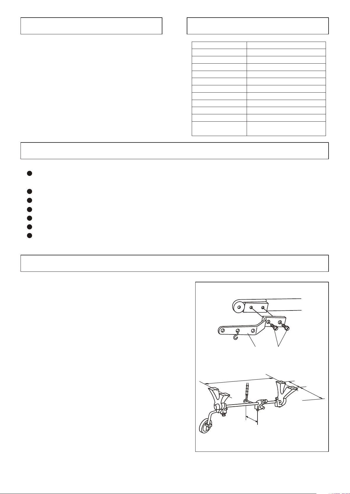
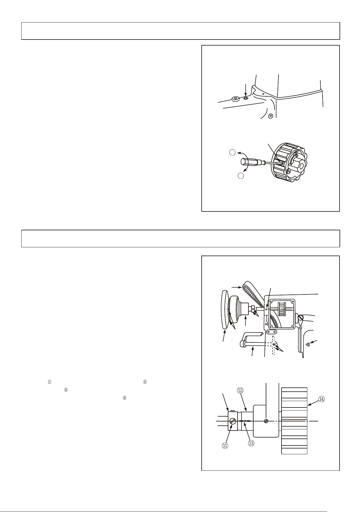
4. In st al li ng t he k ne e li ft er m ec ha ni sm (F ig .1 )
Whe n us e t he kn ee lifte r pe da l, pl ease u s e t he sc re w
to f i x t he kn ee li fter l e ve r .
Kne e li ft er le av er a n d sc re w ar e p ac ke d in th e ac -
ces s or y c ar to n.
272mm
① ②
61mm
100.5mm
To center of V-belt
33.5mm
Page 3
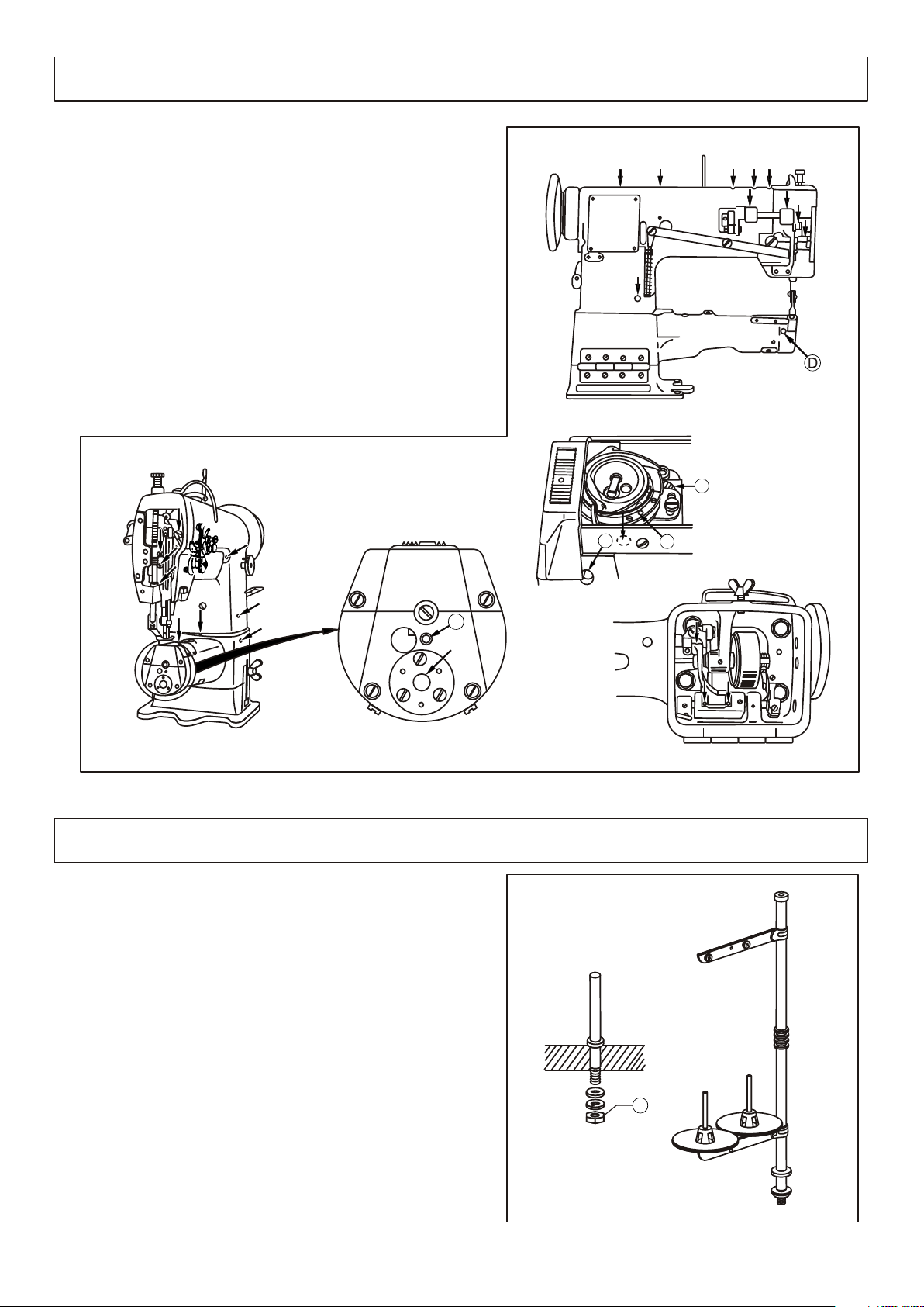
5. Lu br ic at io n( Fi g. 2)
1.B e fore r u nnin g ,ple a se f ill th e o il at th e p lace s a s
arr o w show n .
2.L u bric a ting t h e hook a n d ho ok sha f t sadd l e.
Mov e t he bed s l ide, f ill th e o il i nt the h o le A two o r
thr e e drop s e very d a y,fi l l th e oil in t o the fe l t B four
or fi v e drop s .
3.L u bric a ting t h e feed d o g su ppor t
Bef o re run n ing, p leas e f il l the oi l i nto ho l es C,D , E
two o r t hree d r ops.
B
C
6. In st al li ng t he t hr ea d st an d( Fi g. 3)
The t h re ad s ta nd s ho uld be lo c at ed o n th e ri ght bac k si de
of th e t ab le ,t he n ti ghten t h e nu t C.
E
A
C
Page 4
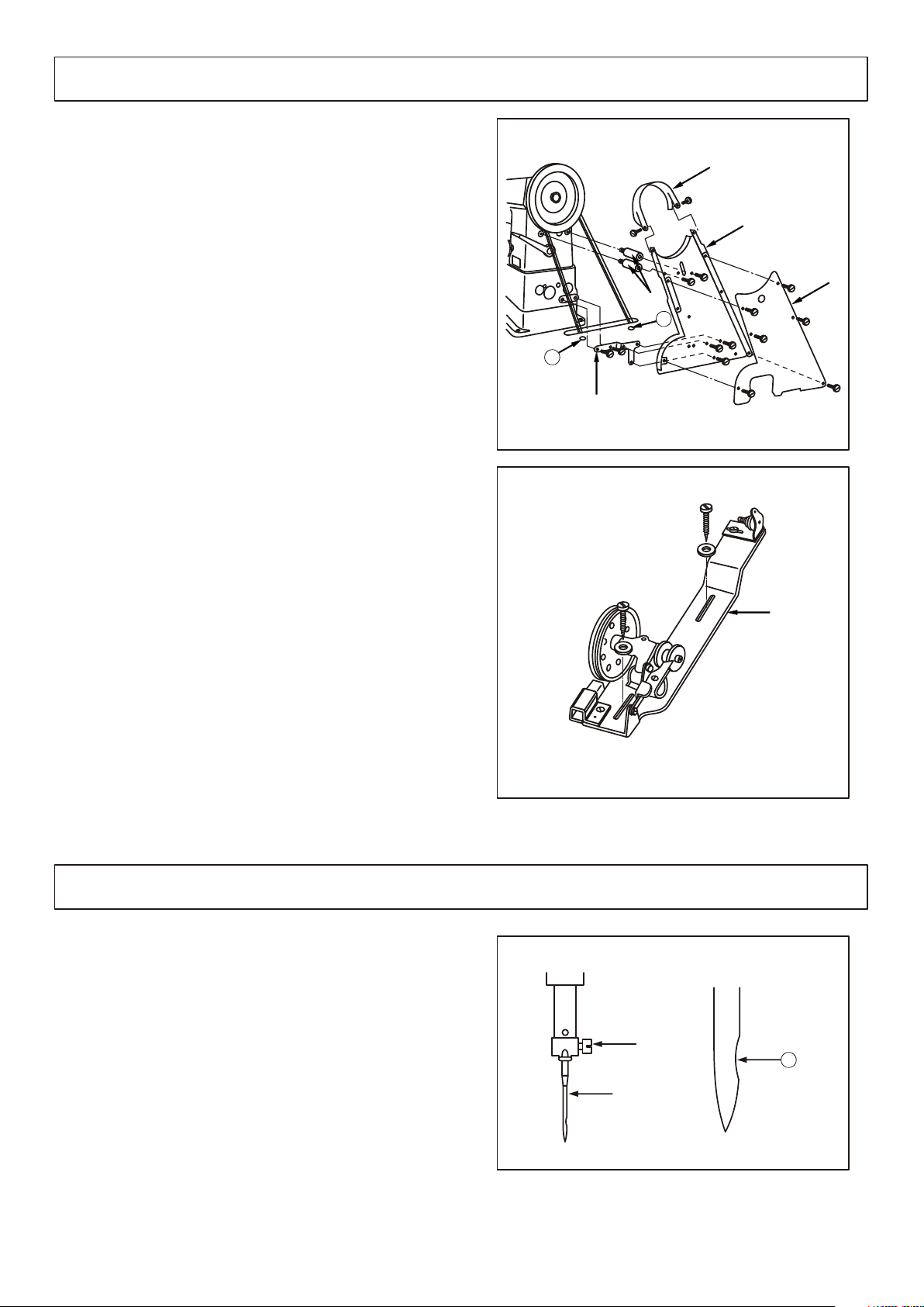
7.Installing the belt cover and bobbin winder(fig.4、5)
1.Install the belt cover support column into the screw
hole;
2.Install the belt cover support plate on the machine
casting;
3.Install the belt cover on the belt cover support
column and the belt cover support plate;
4.Install the bobbin winder into the cover and
adjust it to the proper position;
5.Fix the bobbin winder on the table;
6.Install the V-belt on the hand wheel,the n install the
belt cover and belt cover .
①
④ ⑤
③
⑥ ③
⑥
①
②
⑤
③
④
①
B
A
②
8. In st al li ng t he n ee dl e( fi g .6 )
1.T urn off the pow er;
2.T urn the han d whe el to lif t the nee dle bar to its
hig hes t pos iti on;
3.l oos en the nee dle set scr ew ,an d mak e the nee dle
①
gro ove Ato the rig ht sid e;
4.I nse rt the nee dle sha nk unt il to the bot tom of the
nee dle bar soc ket ;
5.T igh ten the scr ew .
②
②
⑥
②
A
①
Page 5

9. In st al li ng t he b ob bi n ca se (F ig .7 )
1.O p en t he h oo k co ve r,put t h e bo bb in a nd b obbin
Cas e i nt o th e ho ok ;
2.p u t th e bo bb in c as e on the ho o k dr iv in g sh aft,t h en
lay d o wn t he h oo k co ve r.
10 .W in di ng t he b ob bi n th re ad (F ig .8 )
1.T hre ad as fol low ing ord er A,B ,C, the n win d the thr ead
aro und bob bin sev era l cir cle s;
2.P res s dow n the bob bin pre ss pla te ,th e win din g
pul ley wil l be tou che d wit h the V-b elt ;
3.w ind ng amo unt can be adj ust ed by the scr ew ,th e
opt imu m cap aci ty of bob bin thr ead is fil l abo ut 80%
of bob bin out sid e dia met er. Tur n the scr ew clo ckw ise
to inc rea se the win din g amo unt ,co ntr ary ,to dec rea se
the amo unt ;
4.I f the thr ead is not nea t,p lea se mov e the bra cke t
to adj ust is;
5.W hen the win din g is ove r, the bob bin pre ss pla te
wil l be loo se and the bob bin win der wil l sto p aut oma tic all y.
①
②
③
①
A
B
③
C
②
①
11 .P ut t he b ob bi n in to b ob bi n ca se (f ig .9 )
1.D r aw th e t ip of bobbi n th re ad to the ri g ht ,t he n p ut the
bob b in in to bo bb in cas e ;
2.D r aw th e b ob bi n thre a d t hr ou gh the sl i t o n t he
bob b in ca se ,t he n pass t hr ou gh th e thre a d t en si on
spr i ng ,f in al ly ,draw t he th re ad out of t he sl it .
Rem i nd er :i f t he bobbi n is pu t c or rectl y ,t he n d ra w the
bob b in th re ad as A,the b ob bi n w il l rota t es as B.
①
②
②
A
B
①
Page 6
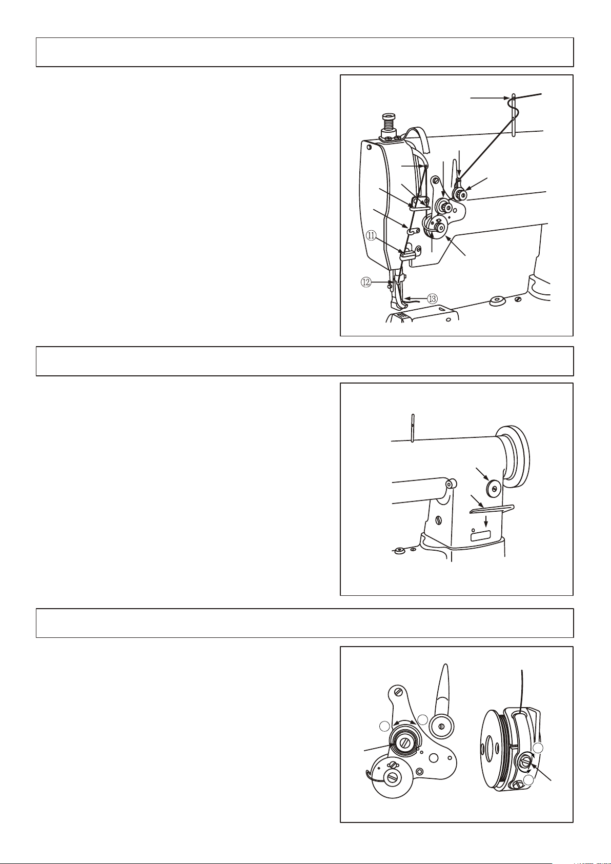
12 .T hr ea di ng t he n ee dl e th re ad (f ig .1 0)
P o s i t i o n t h e n e e d l e b a r o n i t s h i g h e s t , d r a w t h e t h r e a d
f r o m t h e t h r e a d s t a n d a n d t h r e a d a s s h o w n o r d e r
a c c o r d i n g t o F i g . 1 0 .
13 .A dj us ti ng t he s ti tc h le ng th (F ig .1 1)
⑩
⑨
⑦
⑧
⑥
①
②
④
③
⑤
Tur n th e s ti tc h d ial co u nt er -c lo ckwis e or cl oc kw ise to
adj u st th e s ti tc h leng t h. Th e f ig ure on t he di al is the
sti t ch le ng th .( mm)
Rev e rs e f ee d s ti tchin g
1.P r es s t he fe ed leave r do wn wa rd ;
2.W h en pr es s t he feed l e ve r d o wn wa rd , t he fee d in g i s
②
rev e rs e;
3.R e le as e t he fe ed lev e r, th e m ac hine r e co ve rs no rmal
fee d in g a ga in .
14 .T hr ea d te ns io n( Fi g. 12 )
1. Ad ju st in g th e te ns io n of ne ed le th re ad
Tu rn th e te ns io n ad ju st me nt nu t cl oc kw is e( A
di re ct io n) to in cr ea se th e te ns io n of ne ed le th re ad ;t ur n
th e nu t co un te r- cl oc kw is e( B di re ct io n) to de cr ea se th e
te ns io n.
2. Ad ju st in g th e te ns io n of bo bb in th re ad
Tu rn th e te ns io n ad ju st me nt nu t co lc kw is e( C di re cti on )t o in cr ea se th e te ns io n of bo bb in th re ad ; tu rn th e
nu t co un te r- cl oc kw is e( D di re ct io n) to de cr ea se th e
te ns io n.
①
②
①
①
6
5
0
4
3
2
②
B
A
1
C
D
②
Page 7
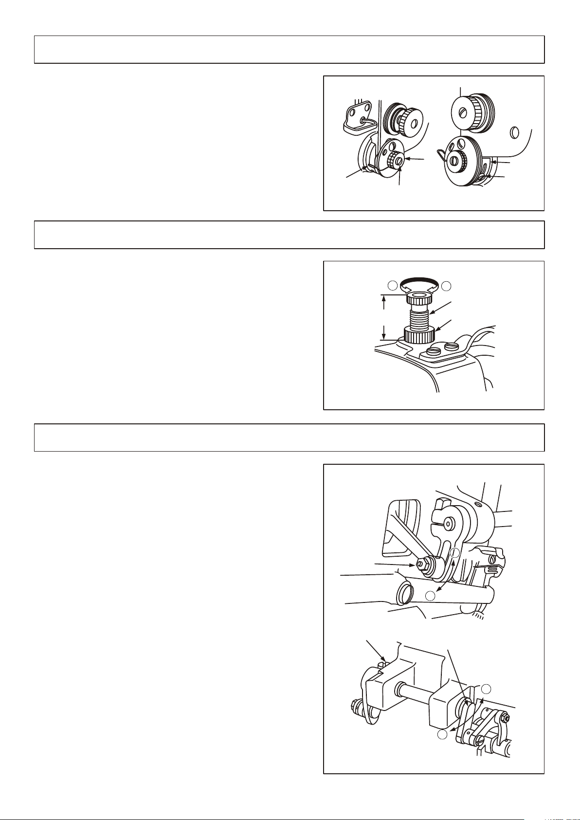
15 .T hr ea d ta ke -u p sp ri ng (f ig .1 3)
1. Ad ju st in g th e th re ad ta ke -u p sp ri ng st ro ke
a. Lo os en th e sc re w ,a nd mo ve th e di sc le ft wa rd
or ri gh tw ar d;
b. Mo ve th e di sc ri gh tw ar d to in cr ea se th e sp ri ng
st ro ke ,c on tr ar y, to de cr ea se th e sp ri ng st ro ke .
2. Ad ju st in g th e te ns io n of th re ad ta ke -u p sp ri ng
Ti gh te n th e nu t ,t ur n th e sp ri ng sh af t co un te rco lc kw is e to in cr ea se th e te ns io n, co tr ar y, to de cr ea se
th e te ns io n. Pl ea se us e a sc re wd ri ve r to ro ta te th e sp ro ng
sh af t to ge t th e re qu ir ed te ns io n.
⑤
② ③
④
①
①
⑤
16 .A dj us ti ng t he p re ss ur e of p re ss er f oo t( Fi g. 14 )
Adj ust the pre sse r foo t pre ssu re acc ord ing to the mat erial s.( the sta nda rd hei ght of pre ssu re adj ust men t scr ew
①
is 25m m).
1.T urn the scr ew clo ckw ise (A dir ect ion )to inc rea se
the pre ssu re, con tra ry, tur n the scr ew cou nte r-
clo ckw ise (B dir ect ion )to dec rea se the pre ssu re,
2.A fte r the pro per pre ssu re is got ,ti ght en the nut .
①
①
②
B
Standar d
25mm
④
③
②
A
①
②
17 .A dj us ti ng t he h ei gh t of p re ss er f oo t( fi g. 15 )
1.Th e optimum fixed position of presser foot is to adjust
The p res ser foo t to the “ 1/8” indication line on
The f eed cra nk.
Loosen the nut and adju st t he c am l ink ass embl ing
position.
a.At he highest position A, the max .Presser foot
Vertical stroke is got;
b.At the lowest position B, the mi n. Presser foot
vertical stroke is got.
2.Us ually, t he s rtoke of outer presser foot is same as that of
the inner presser foot.
A.Loosen the screw ;
b.When the thread take-up lever is at its highest
position,lay down the presser bar lever;
c.Ad just the feed crank to leftward( A dir ect on)
to increase the presser foot stroke.contrary,adjust
the feed crank to rightwa rd (b dir ect ion ) to
decrease the presser foot stroke.
①
③
②
①
②
③
AAA
B
③
B
A
Page 8
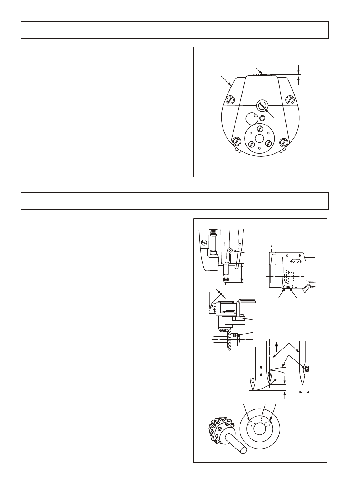
18 .A dj us ti ng t he h ei gh t of f ee d do g( Fi g. 16 )
The s ta nd ar d p os ition o f f ee d d og i s 1 mm highe r th an th e
sur f ac e o f t hr oa t plat e .
Ple a se ad ju st it as fol o wi ng or de r acco r di ng to se wing
req u ir em en t o r a fter c h an ge a n ew feed d o g:
1.P l ea se co nf ir m the h i gh es t p os ition o f f ee d d og ;
2.l o os en th e s cr ew ;
3.T h e h ei gh t c an be adj u st d b y t ur ning e c ce nt ri c p in(P2 2 ).
4.A f te r t he re qu red he i gh t i s g ot , tigh t en th e s cr ew .
②
③
①
③
19 .A dj us ti ng t he n ee dl e an d ho ok (F ig .1 7)
②
①
1 mm
③
1.Adjust the stitch dial to figure“ 3”
2.Turn the hand wheel to lower the needle bar to its
lowest position, and loosen the scrwe ;
3.confirm the standard height of needle bar:Lif t th e
needle bar up to 2.4mm from its lowest position, there
should be1.7mm clearance hetween upside of n eed le
hole and the tip of hook blade ;the low est pos iti on
of needle bar is that there is a clearance of 55.2mm
from the bottom of needle bar rocking frame to the
bottom of needle bar.
4.Loosen the screw ,move the g ear cov er , an d
loosen the screw and screw ;
5.Loosen the screw ,move the h ook sha ft s add le l eft ward or rightward,assure the clearance between the
tip of hook blade and needle is 0~0 .5m m, a fte r
finish, tighten the screw;
6.Make the tip of hook blade align with the center of
needle bar,then tighten the screw ;
7.Turn the hand wheel clockwise, tighten the screws
alternately.
③ ②
④ ⑧
⑤
⑥
⑦
①
④
⑧
0~0.05m m
①
55.2mm
⑤
④
②
③
⑦
⑥
1.7mm
2.4mm
0~0.05m m
④ ⑧⑧
Page 9
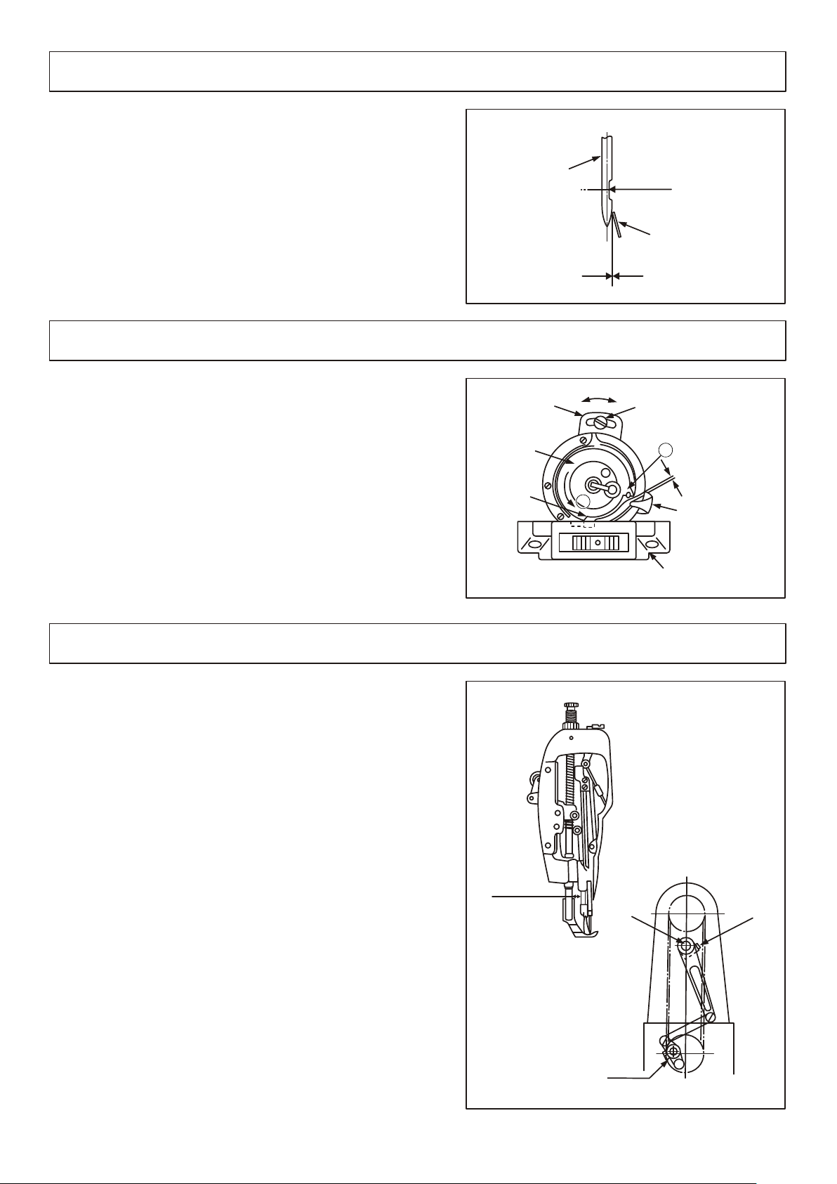
20 .A dj us ti ng t he n ee dl e gu ar d pl at e( Fi g. 18 )
Aft e r c ha ng in g h ook , p l ea se co nf irm th e po si ti on of
nee d le gu ar d p la te. Th e st an da rd posit i on of ne ed le gua r d
pla t e i s t ha t n ee dle gu a rd pl at e i s to uc hed wi t h t he
fla n k s id e o f n ee dle sli g ht ly , i f not, b en d t he pl ate an d
adj u st th e p os it ion:
1.I f th e n ee dl e g uard p l at e b en ds inwar d , p le as e a djust
the p la te ou tw ar d with a sc re wd ri ver;
2.I f th e n ee dl e g uard p l at e b en ds outwa r d, pl ea se adjus t
the p la te in wa rd with a s cr ew dr iv er;
①
②
21 .A dj us ti ng t he i nn er h oo k gu id e( Fi g. 19 )
①
0~0.05m m
②
1.T u rn th e h an d w heel t o ma ke th e i nner h o ok gu id e
rea c h i ts fi na l p ositi o n;
2.T u rn th e b ob bi n case a s t he di re ction s ho wn by ar row
Bun t il to th e s li t of th r oa t p la te ;
3.L o os en th e s cr ew , th e move t he ad ju st ing pl a te
of i n ne r h oo k g ui de as a r ro w s ho wn direc t io n, as su re
the c le ar an ce be tween t he in ne r h ook gu i de an d t he
bob b in ca se fl an ge is a b ou t 0 .1 ~0 .15mm .
⑤ ⑥
④
①
③
②
⑥
⑤
A
0.1~0.1 5 m m
BB
B
①
④
22 .A dj us ti ng t he l en gt hw ay s po si ti on o f ne ed le b ar f ra me (F ig .2 0)
1.Adjusting the relationship between the inner presser
foot bar and pressing bar:
a.Adjust the stitch dial to min.figure;
③
①
7.5mm
②
①
b.Loosen the screw , adjust the distance between
theinner presser foot bar and pressing bar to
7.5mm.
Note:Dont make any clearance at axis direction of
needle bar frame.
2.Adjusting the relationship between the feed dog and
needle bar:
a.Adjust the stitch dial to min.figure;
b.Loosen the screw ;
c.Adjust the position of feed dog to make the needle
ali gn with the center of needle hole on the throat
plate(towards to the operator slightly).
③
Page 10
23 .S af et c lu tc h de vi ce (F .2 1)
If t h e h oo k b lo ck s the t h re ad wh en runni n g , th e s af ety
clu t ch de vi ce wi ll wor k , w hi ch ma ke the l ow er ti mi ng
pul l ey ro ta te wi thout l oa d.
1.R e st or e a s f ol lowin g or de r:
a.c l ea n t he th re ad blo c ke d i n t he hook;
b.P r es s t he bu tt on a nd turn t h e h an d w he el at r e ve rs e
dir e ct io n.
2.A d ju st in g t he force o f s af et y c lutch :
Tur n th e s cr ew c lockw i se (A di re ction ) to in cr ea se
the f or ce , c on ta ry, tu r n t he sc re w coun t er -c lo ck wise( B
dir e ct io n) to de creas e th e f or ce .
②
①
①
②
B
A
24 .R el oa di ng t he t im in g be lt (F ig .2 2)
1.U n lo ad in g t he timin g be lt :
a.L o os en th e s cr ew , , , , ;
b.T a ke th e h an d w heel an d b us hing do w n ;
c.P u ll th e f ee d l ever , o u t wa rd to m a ke th e t im ing
bel t ha v e en ough s p ac e t o p as s thro u gh ;
d.T a ke do wn th e b elt an d ta ke it ou t from t he bu sh lo le of
upp e r s ha ft .
2.R e lo ad in g t he timin g be lt ;
a.T h e l oa di ng or der of t im in g b el t is th e re ve rs e o rder
of u n lo ad in g;
b.A d ju st in g t he timin g re la ti on ship b e tw ee n u pp er
sha f t a nd lo we r s haft;
Tur n th e h an d w he el to l i ft th e t hr ead ta k e- up le ve r to
its h ig he st po si tion, t ur n t he lo wer sh a ft to ma ke the fi r st
scr e w o n t he co ll ar a li gn wit h th e m ar k o n the
rea r bu sh in g o f l ower s h af t, un de r this c on di ti on , inst a ll
the b el t o n t he lo wer ti m in g p ul le y .
⑧
① ② ③ ④ ⑤
⑥ ⑦
⑨
⑩
⑥
⑩
⑧
①
③
②
⑦
⑤
④
⑨
Page 11

25 .T ro ub le s ho ot in g
Tr oub le
1.T h re ad b re ak ag e
(th r ea d we ar a nd
tea r )
2.S k ip s ti tc h
Ca use s
① Thr e ad in g co ur se ,need l e ti p, h oo k bl ade
tip o r t hr ea d pa ss in g groov e o n th e th ro at
pla t e is r ou gh .
② Too l a rg e ne ed le t hr ead ten s io n.
③ Too b i g cl ea ra nc e of i nner ho o k gu id e.
④ col l is io n be tw ee n needl e a nd h oo k gu id e
tip .
⑤ Too s m al l ne ed le t hr ead ten s io n.
⑥ TOO l ar ge o r to o sm al l strok e t hr ea d ta ke
-up s p ri ng t en si on
⑦ Not t i mi ng b et we en n eedle a n d ho ok .
① Too b i g clea r ance b e twee n n ee dle an d
the t i p of inn e r hook b l ade.
② Not t i ming b e twee n n eedl e a nd h ook.
③ Too s m all pr e ssur e o n the ou t er p ress e r
foo t .
④ the h e ight o f n eedl e b ar is no t e no ugh.
⑤ No ef f ect of n e edle g u ard pl a te .
⑥ Wro n g need l e size .
⑦ Wro n g need l e thre a ding .
⑧ Rot a ry hoo k i s scra p ed.
So lut ion
Get r i d of t he b ur r on t he h ook bla d e ti p
and p o li sh t he t hr ea d passi n g gr oo ve o n
the t h ro at p la te w it h fine em e ry c lo th .
Adj u st t he n ee dl e th read to p r op er t en si on.
Dec r ea se t he c le ar ance, r ef er t o2 1.
Adj u st in g th e in ne r hook gu i de .
Rdf e r to 1 9. A dj us ti ng the ne e dl e an d
hoo k .
Adj u st t he n ee dl e th read to p r op er t en si on.
Dec r ea se t he t en si on of thr e ad t ak e- up
Spr i ng a nd i nc re as e the spr i ng s tr ok e.
Ref e r to 1 9. A dj us ti ng the ne e dl e an d ho ol .
Ref e r to 1 9. Ad ju st ing the n e ed le a nd h oo k.
Ref e r to 1 9. Ad ju st ing the n e ed le a nd h oo k.
Tig h te n th e pr es su re scre w .
Ref e r to 1 9. Ad ju st ing the n e ed le a nd h oo k.
Ref e r to 2 0. Ad ju st ing the n e ed le g ua rd
pla t e.
Cha n ge a p ro pe r ne ed le.
Ref e r to 1 2. Th re ad ing the n e ed le t hr ea d.
Get r i d of t he b ur r on t he h ook gui d e ti p
wit h f in e em er y cl ot h.
3.L o os e st it ch
① Th e thr e ad pa ssi ng pa rts a re no t smoo th.
② th e bob b in ca nno t rot ate s moo thly .
③ To o big c l ear anc e of in ner h ook g uide .
④ To o wea k t ens ion o f bob bin t hre ad.
⑤ to o tig h ten w hen w ind ing b obb in thr ead .
⑥ bo bbi n g thr ead d oes n't p ass t he thr ead
te nsi o n spr ing o n the b obb in ca se
Po lis h t hem w ith f ine e mer y c lot h.
Re set t h e bob bin a nd ro tar y h ook .
Re fer t o 2 1. Ad jus tin g the i n ner h ook
gu ide .
Ad jus t t he bo bbi n thr ead t e nsi on pr ope rly .
De cre a se th e ten sio n whe n w ind ing .
Th rea d ing t he bo bbi n thr e ad co rre ctl y.
Page 12

1.C ast ing c omp one nts
31
36
32
34
30
29
46
12
48
20
18
16
15
17
19
42
41
13
9
14
11
1
2
8
7
6
33
35
33
27
40
39
10
22
47
21
23
24
25
3
4
37
45
28
26
44
5
25
43
38
Page 13

1.C ast ing c omp one nts
Re f.N O .
1
2
3
4
5
6
7
8
9
10
11
12
13
14
15
16
17
18
19
20
21
22
23
24
25
26
27
28
29
30
31
32
33
34
35
36
37
38
39
40
41
42
43
44
45
46
47
48
Pa rts N o .
50 W F2-0 04
16 W F1-0 59
50 W F2-0 05
13 W F2-0 08
50 W F2-0 08
50 W F2-0 09
1W F -038
50 W F2-0 10
16 W F2-0 12
7W F 5-01 7
50 W F2-0 13
50 W F2-0 12
50 W F2-0 11
50 W F2-0 19
50 W F2-0 20
7W F 4-00 4
50 W F2-0 14
16 W F2-0 15
50 W F2-0 21
19 W F4-0 02
50 W F2-0 22
1W F 1-02 6
16 W F2-0 15
50 W F2-0 15
50 W F2-0 16
50 W F2-0 23
10 6 WF2- 001
50 W F2-0 24
50 W F2-0 27
10 6 WF2- 002
50 W F2-0 28
50 W F2-0 29
50 W F2-0 31
50 W F2-0 32
50 W F2-0 30
50 W F2-0 25
50 W F2-0 26
50 W F2-0 03
50 W F3-0 90
50 W F3-0 91
50 W F1-0 55
50 W F2-0 06
50 W F2-0 07
1W F 1-01 6
22 W F5-0 27
Na me of p a rts
Fa c e plat e
Sc r ew
Ge a r cove r
Sc r ew
Sc r ew
Ru b ber pl ug
Th r ead ta ke-u p le ver c o ver
Sc r ew
Co n nect ing ho ok
Th r ead gu ide( mi ddl e )
Sc r ew
Si d e plat e
Wi n g bolt
Sc r ew
Oi l p an
Fe l t
Oi l a ick
Sc r ew
Th r ead gu ide( up per )
Sc r ew
Ta k e-up o il spl as her
Sc r ew
Ta k e-up s prin g ad jus t ing p l ate
Sc r ew
Sc r ew
Th r oat gu ide( lo wer )
Fe l t
Th r oat pa te bas e
Th r oat pl ate ba se
Sc r ew
Th r oat pl ate
Sc r ew
Le f t side p late
Sc r ew
Be d s lide
Ri g ht sid e plat e
Lo w er sha ft fro nt c ove r
Sc r ew
Ma c hine b ase
Ru b ber pl ug
Oi l t ube
Oi l t ube
Oi l t ube
hi n ge
Th r oat pl ate ba se
Sc r ew
Cy l inde r bed co ve r(l o wer )
Le f t scre w
Ri g ht scr ew
Qt y.
1
2
1
2
8
1
1
2
1
1
4
1
1
1
1
1
1
2
1
2
1
1
1
1
2
1
1
1
1
2
1
1
2
1
4
1
1
1
3
1
2
1
1
1
1
1
4
1
1
1
Re mar k s
SM9 / 64” ×40
SM9 / 64 ”×4 0
GB7 0 -8 5 M 8 × 2 0
SM1 5 /6 4” ×28
SM1 1 /6 4” ×40
SM1 1 /6 4” ×40
SM9 / 64 ”×4 0
SM9 / 64 ”×4 0
SM9 / 64 ”×4 0
SM9 / 64 ”×4 0
For 3 41
For 3 41 N
SM1 1 /6 4” ×40
SM1 1 /6 4” ×40
SM9 / 64 ”×4 0
SM1 1 /6 4” ×40
#1
#1S M 11 /6 4” ×40
SM9 / 64 ”×4 0
SM9 / 64 ”×4 0
Page 14

2.U ppe r sha ft an d thr ead t ake - up l e av e r com pon ent s
7
6
14
2
3
15
17
16
24
19
18
23
35
50
34
32
9
20
21
11
26
36
12
22
45
46
28
38
41
27
37
10
42
43
13
63
59
62
29
30
28
27
31
5
25
1
40
39
50
30
40
44
52
60
61
53
57
54
48
47
8
58
56
38
51
55
49
4
33
Page 15

2.U ppe r sha ft an d thr ead t ake - up l e ve r c omp one nts
Re f.N O .
1
2
3
4
5
6
7
8
9
10
11
12
13
14
15
16
17
18
19
20
21
22
23
24
25
26
27
28
29
30
31
32
33
34
35
36
37
38
39
40
41
42
43
44
45
46
47
48
49
50
51
52
53
54
55
56
57
58
59
60
61
62
63
Pa rts N o .
16 W F-0 1 0
50 W F1- 0 22
50 W F1- 0 04
50 W F1- 0 05
50 W F3- 0 43
18 2 27
50 W F1- 0 06
50 W F1- 0 62
50 W F1- 0 57
50 W F1- 0 15
50 W F1- 0 14
50 W F1- 0 08
50 W F1- 0 11
50 W F1- 0 09
50 W F1- 0 13
50 W F1- 0 12
50 W F1- 0 10
50 W F1- 0 16
50 W F1- 0 19
50 W F1- 0 17
50 W F1- 0 18
18 2 27
50 W F3- 0 34
50 W F1- 0 62
50 W F1- 0 24
50 W F1- 0 25
50 W F1- 0 13
50 W F1- 0 19
50 W F1- 0 35
50 W F1- 0 21
50 W F1- 0 22
50 W F1- 0 20
50 W F1- 0 23
50 W F1- 0 28
50 W F1- 0 19
50 W F1- 0 29
50 W F1- 0 27
50 W F1- 0 32
16 W F1- 0 43
21 W F6- 0 07
50 W F1- 0 30
50 W F1- 0 51
50 W F1- 0 53
50 W F1- 0 52
50 W F1- 0 34
16 W F3- 0 46
22 W F1- 0 13
22 W F1- 0 18
22 W F1- 0 16
22 W F1- 0 14
22 W F1- 0 17
Na me of p a rts
Pl u g
ta k e-u p l ever p in
Oi l w ick
Sc r ew
Oi l w ick
Sc r ew
Th r ead t a ke-u p leav er
Fe e d cam
Sc r ew
Oi l w ick
Ta k e-u p l ever s lidi ng blo ck
Oi l w ick
Hi n ge sc r ew
Ne e dle b a r cran k rod
Up p er sh a ft
Oi l w ick
Pl u g
Oi l w ick
Cr a nk pi n
Ne e dle b a r cran k
Sc r ew
Sc r ew
Sc r ew
Sc r ew
Up p er sh a ft bus h(fr ont)
Sc r ew
Oi l f elt
Oi l f elt
Up p er sh a ft bus h(mi ddle )
Sc r ew
Oi l f elt
Up p er sh a ft bus h(up per)
Se t s cre w
Sc r ew
Sc r ew
Sc r ew
Up p er sh a ft bea ring b ush
Sc r ew
Up p er sh a ft bus h(re ar)
Be a rin g
Re a tai n ing co llar
Ha n d whe e l
Sc r ew
Sc r ew
Ti m ing b e lt
Sp r ing p i n
Ti m ing p u lley (low er)
Sp r ing r i ng
Sc r ew
Sc r ew
Sa f ety c l utch p ush bu tton
Pu s h but t on cyl inde r
Sa f ety c l utch d isc
Sa f ety b a se
Sp r ing
Sa f ety c l utch s prin g
Sa f ety c l utch h ook
Sa f ety c l utch c ount er-h ook
Co u nte r -hoo k spri ng
Sa f ety c l utch l ink
Sa f ety c l utch l ink pi n
Qt y.
2
1
1
2
1
1
1
1
2
1
1
1
1
1
1
1
1
1
1
1
1
1
1
1
1
1
2
2
1
2
1
1
1
1
1
1
1
2
1
2
1
1
1
1
1
1
1
1
1
2
2
1
1
1
1
1
1
1
1
1
1
1
1
Re mar k s
SM1 5 /6 4”×2 8
SM1 5 /6 4”×2 8
SM1 / 4”×4 0
SM9 / 32” ×28
SM9 / 32” ×28
SM9 / 32” ×28
SM9 / 32” ×28
SM1 5 /6 4”×2 8
SM1 / 4”×4 0
GB8 9 4. 2- 86 2 6
15× 3 5 1 1 ( 20 2)×
SM1 5 /6 4”×2 8
SM1 5 /6 4”×2 8
GB8 7 9- 86 2×1 0
SM9 / 64” ×40
SM5 / 16” ×24
Page 16

3.N eed le ba r and h ook d riv ing s h af t c om p one nts
1
22
23
25
4
5
3
24
2
10.11.12
7
6
29
30
31
32
33
15
14
13
9
8
17
19
20
18
36
16
34
21
35
59
63
28
26
27
43.44.45.46.47
51
37
38
39
50
48
52
57
57
41
42
40
54
53
62
37
38
61
60
58
49
55
56
Page 17

3.N eed le ba r and h ook d riv ing s h af t c om p one nts
Re f.N O .
1
2
3
4
5
6
7
8
9
10
11
12
13
14
15
16
17
18
19
20
21
22
23
24
25
26
27
28
29
30
31
32
33
34
35
36
37
38
39
40
41
42
43
44
45
46
47
48
49
50
51
52
53
54
55
56
57
58
59
60
61
62
63
Pa rts N o .
50 W F3- 0 01
50 W F3- 0 02
50 W F3- 0 03
50 W F3- 0 04
50 W F3- 0 05
50 W F3- 0 06
50 W F3- 0 07
50 W F3- 0 08
50 W F3- 0 10
50 W F3- 0 09
50 W F3- 0 11
50 W F3- 0 12
50 W F3- 0 13
50 W F3- 0 14
34 T 5-5 4 0
36 T 5-0 0 8E5
50 W F1- 0 01
50 W F1- 0 03
22 - WF3 - 014
22 T 2-0 1 7
50 W F1- 0 02
33 T 1-0 2 7
50 W F1- 0 47
50 W F1- 0 48
50 W F1- 0 46
16 W F2- 0 17
50 W F1- 0 49
50 W F1- 0 50
10 6 WF1 - 001
50 W F5- 0 45
50 W F1- 0 44
50 W F1- 0 43
50 W F1- 0 31
50 W F3- 0 16
50 W F3- 0 17
50 W F1- 0 40
50 W F1- 0 36
50 W F1- 0 37
50 W F1- 0 38
50 W F1- 0 22
50 W F1- 0 41
50 W F1- 0 39
50 W F1- 0 42
17 0 27
Na me of p a rts
Ne e dle ba r rock ing fr a me as s emb l y
Ne e dle ba r rock ing fr a me sh a ft
Ne e dle ba r slid e bloc k Pin
Ne e dle ba r rock ing fr a me
Fe l t
Re t aine r
Ro c king s haft b ush( f ron t )
Ro c king s haft b ush( r ear )
Wa s her
Wa s her
Wa s her
Wa s her
Sc r ew
Ro c king s haft c rank
co n nect ing ro d
Hi n ger sc rew
Nu t
Fe e d shaf t cran k
Sc r ew
Sc r ew
Ne e dle ba r
Ne e dle ba r conn ecti o n
Fe l t
Sc r ew
Ne e dle
Sc r ew
Ne e dle ba r thre ad gui d e
Bo b bin
Ro t ary ho ok
In n er hoo k guid e
Sl i de blo ck
Sl i de blo ck pin
]S c rew
Sc r ew
Ad j usti ng pla te
Sc r ew
Wa s her
Ho o k shaf t sadd le ass e mbl y
Ho o k shaf t sadd le
Ho o k shaf t sadd le
Ho o k shaf t bush (upp e r)
Ho o k shaf t bush (low e r)
Wa s her
Wa s her
Wa s her
Wa s her
Wa s her
Ho o k shaf t gear
Lo w er sha ft
Fe e d cam
Sc r ew
Lo w er sha ft bev el gea r
Lo w er sha ft bus h(fr o nt)
Oi l f elt
Lo w er sha ft bus h(re a r)
Sc r ew
Sc r ew
Fe l t
Fe l t
Lo w er sha ft col lar
Sc r ew
Oi l w ick
Fe l t
Qt y.
1
1
1
1
1
1
1
1
1
1
1
1
1
1
1
1
2
2
1
1
1
1
1
1
1
1
1
1
1
1
1
1
1
1
1
1
2
2
1
1
1
1
1
1
1
1
1
1
1
1
1
2
1
1
1
1
1
3
1
1
1
2
1
1
Re mar k s
GB1 1 7- 86 A 5×28
T=1 . 5
T=1 . 35 # 1
T=1 . 65 # 1
T=1 . 65
SM1 5 /6 4”×2 8
SM1 5 /6 4”×2 8
SM1 1 /6 4”×4 0
SM9 / 64” ×40
DP×17
SM1 / 8”×4 0
SKR T 34 1- NR
SM9 / 64” ×40
GB7 0 -8 5 M5×1 2
GB9 5 -8 5 5
For 3 41
For 3 41 N
T=1 . 88 # 1
T=1 . 92 # 1
T=1 . 96 # 1
T=2 . 00 # 1
T=2 . 04 # 1
SM1 5 /6 4”×2 8
SM1 5 /6 4”×2 8
SM1 / 4”×4 0
SM1 1 /6 4”×4 0
Page 18

4.P res ser f oot c omp one nts
9
8
24
1
10
12
13
14
15
22
23
18
16
21
20
7
3
2
11
6
17
19
4
5
Page 19

4.P res ser f oot c omp one nts
Re f.N O .
1
2
3
4
5
6
7
8
9
10
11
12
13
14
Pa rts N o .
22 W F3-0 05
50 W F4-0 01
50 W F1-0 22
22 W F3-0 14
50 W F4-0 02
50 W F4-0 11
50 W F4-0 17
50 W F4-0 15
1K T 4-00 1
1K T 4-00 2
50 W F4-0 06
50 W F4-0 07
50 W F4-0 08
50 W F4-0 14
Na me of p a rts
Pr e sser b ar
Pr e sser b ar l owe r b ush
Sc r ew
Sc r ew
Ou t er pre ss er fo o t asse mbly
co n nect in g pin r o ller
Pr e sser b ar b rac k et gui de
Gu i de pla te b ase
Pr e ssur e ad jus t ment s crew
Nu t
Pr e sser s pr ing
Ha n d lift er
Ha n d lift er p in
Hi n ge scr ew
Qt y.
1
1
1
1
1
1
1
1
1
1
1
1
1
1
Re mar k s
SM1 5 /6 4” ×28
SM9 / 64 ”×2 8
15
16
17
18
19
20
21
22
23
16 0 34
50 W F4-0 09
50 W F4-0 10
50 W F4-0 13
50 W F4-0 12
50 W F4-0 18
50 W F4-0 19
22 W F2-0 17
50 W F4-0 16
Sc r ew
Pr e sser l if tin g l ever b ase
Sc r ew
Sp r ing
Th r ead re le ase g u ide as semb l y
Pr e sser b ar l ift i ng lev er
Hi n ge scr ew
Sc r ew
Sc r ew
1
1
1
1
1
1
1
3
1
SM1 1 /6 4” ×40
SM3 / 16 ”×3 2
SM1 5 /6 4” ×28
Page 20

5.U ppe r fee d mec han ism c omp o ne n ts
28
21
3
4
16
14
19
6
5
7
8
24
15
13
20
17
18
22
12
11
23
10
9
1
27
28
26
25
2
Page 21

5.U ppe r fee d mec han ism c omp o ne n ts
Re f.N O .
1
2
3
4
5
6
7
8
9
10
11
12
13
14
15
16
17
18
19
20
21
22
23
24
25
26
27
28
Pa rts N o .
55 W F3-0 18
50 W F3-0 19
50 W F3-0 21
50 W F3-0 22
50 W F3-0 23
50 W F3-0 25
50 W F3-0 26
50 W F3-0 27
50 W F3-0 31
50 W F3-0 32
50 W F3-0 36
22 W F4-0 40
50 W F3-0 35
50 W F3-0 38
50 W F3-0 37
50 W F3-0 40
50 W F3-0 41
50 W F3-0 42
50 W F3-0 24
50 W F3-0 20
50 W F3-0 39
50 W F3-0 33
16 W F1-0 59
50 W F3-0 29
50 W F3-0 30
17 0 78
1W F 1-01 1
Na me of p a rts
In n er pre sser f oot ba r
In n er pre sser f oot
Bu s hing
Up p er fee d shaf t
Sc r ew stu d
Up p er fee d conn ecti ng lin k
Up p er fee d sewi ng pla te
In n er pre sser f oot dr ivin g li nk
In n er pre sser f oot ro d
In n er pre sser f oot sp ring
Fe l t
Fe l t reta iner
Up p er fee d driv ing ro d
Up p er fee d cran k
co n nect ing st ud
Hi n g scre w
Wa s her
Nu t
Nu t
Sc r ew
Sc r ew
In n er pre sser f oot re atai ni ng pl a te
Sc r ew
Oi l w ick
Sl i de blo ck
Sl i der bl ock ho lder
Sc r ew
Sc r ew
Qt y.
1
1
2
1
1
1
1
1
1
1
1
1
1
1
1
1
1
1
1
1
1
1
2
2
1
1
1
2
Re mar k s
SM1 1 /6 4” ×40
SM1 / 4” ×40
SM1 1 /6 4” ×40
SM1 / 4” ×24
SM9 / 64 ”×4 0
SM1 1 /6 4” ×40
SM1 1 /6 4” ×40
Page 22

6.L owe r fee d mec han ism o mpo n en t s
53
54
4
58
1
59
10
7
8
9
6
11
5
14
52
2
23
24
22
15
16
21
51
56
3
40
44
25
41
20
60
42
19
18
13
17
63
28
25
50
61
10
62
11
29
12
60
57
30
38
37
36
34
39
33
37
31
35
36
32
44
43
45
25
46
27
47
26
64
65
48
55
49
Page 23

6.L owe r fee d mec han ism c omp one nts
Re f.N O .
1
2
3
4
5
6
7
8
9
10
11
12
13
14
15
16
17
18
19
20
21
22
23
24
25
26
27
28
29
30
31
32
33
34
35
36
37
38
39
40
41
42
43
44
45
46
47
48
49
50
51
52
53
54
55
56
57
58
59
60
61
62
63
64
65
Pa rts N o .
55 W F3-0 44
55 W F3-0 45
50 W F3-0 17
50 W F3-0 46
J0 . 0.40
50 W F3-0 47
50 W F3-0 49
50 W F3-0 17
50 W F3-0 15
50 W F3-0 51
50 W F3-0 50
50 W F3-0 53
50 W F3-0 52
50 W F3-0 59
50 W F3-0 56
50 W F3-0 55
50 W F3-0 57
17 W F4-0 35
50 W F3-0 58
50 W F3-0 62
50 W F3-0 66
16 0 56
50 W F3-0 17
50 W F3-0 68
50 W F3-0 69
50 W F3-0 74
10 6 WF3- 001
50 W F3-0 92
50 W F3-0 70
50 W F3-0 71
50 W F3-0 72
50 W F3-0 84
10 6 WF3- 003
50 W F3-0 85
50 W F3-0 86
10 6 WF3- 002
22 W F4-0 14
50 W F3-0 80
50 W F3-0 83
50 W F3-0 81
50 W F3-0 82
50 W F3-0 89
50 W F3-0 87
50 W F1-0 22
50 W F3-0 88
50 W F3-0 75
50 W F3-0 24
50 W F3-0 78
50 W F3-0 79
18 2 27
50 W F3-0 76
50 W F1-0 19
50 W F3-0 48
50 W F3-0 67
50 W F3-0 60
50 W F4-0 40
50 W F3-0 36
50 W F3-0 77
50 W F3-0 61
50 W F3-0 64
50 W F1-0 22
1W F 2-02 9
50 W F3-0 63
1W F 2-01 0
50 W F3-0 65
50 W F3-0 73
22 W F3-0 14
Na me of p a rts
Fe e d conn ecti on r od
Hi n ge pin
Sc r ew
Re v erse f eed dr iv ing r o cker
Sc r ew
Re v erse f eed dr iv ing r o cker s haft
Bu s hing
Sc r ew
Pi n
Sc r ew
Sl i de blo ck
Li n k
Sl i de blo ck sha ft
Fe e d regu lato r ba se
Sc r ew
St i tch di al
Sc r ew
Pi n
Sp r ing
Re v erse f eed le ve r sha f t
Re v erse f eed le ve r sha f t cran k
Sc r ew
Sc r ew
Re v erse f eed cr an k lin k
Hi n ge scr ew
Cr a nk
Cr a nk
Ec c entr ic pin
Te n sion s prin g
Sc r ew
Su s pens ion ho ok
Fe e d bar cr ank
Fe e d bar cr ank
Oi l f elt
Fe e d dog
Fe e d dog
Sc r ew
Fe e d dog su ppor t
Sc r ew
Fe n ce
Sc r ew
Sc r ew
Fe e d dog su ppor t cr ank
Sc r ew
Pi n
Fe e d shaf t bush in g(f r ont)
Nu t
Fe e dsha ft
Fe e d shaf t coll ar
Sc r ew
Fe e d shaf t bush in g(r e ar)
Sc r ew
Sc r ew
Co n nect ion ro d
Fe e d regu lato r bu shi n g
Fe l t reta iner
Oi l f elt
Oi l f elt
Hi n ge pin
Re v erse f eed le ve r
Sc r ew
Sc r ew
Sc r ew
Sc r ew
Sc r ew
Oi l w ick
Wa s her
Sc r ew
Qt y.
1
1
1
1
1
1
1
1
1
2
2
1
1
1
1
1
1
1
1
1
1
2
1
1
4
1
1
1
1
1
1
1
1
1
1
1
1
1
2
1
4
1
1
1
1
1
2
1
1
2
1
1
1
1
1
1
1
1
1
1
1
1
2
1
1
1
1
1
Re mar k s
SM1 1 /6 4”×2 8
SM1 5 /6 4”×2 8
SM9 / 64” ×40
SM3 / 16” ×28
SM3 / 64” ×28
SM1 5 /6 4”×2 8
For 3 41
For 3 41 N
For 3 41
For 3 41 N
For 3 41
For 3 41 N
SM1 / 8”×4 4
SM1 1 /6 4”×4 0
SM1 5 /6 4”×2 8
SM1 / 4”×4 0
SM1 / 4”×4 0
SM1 5 /6 4”×2 8
SM1 5 /6 4”×2 8
SM1 5 /6 4”×2 8
SM1 5 /6 4”×2 8
SM3 / 16” ×32
SM1 / 4”×4 0
SM1 / 4”×4 0
SM9 / 64” ×40
Page 24

7.T hre ad th nsi on co mpo nen t s
2
30
31
1
3
4
5
6
7
11
9
12
10
8
13
21
14
25
15
22
16
23
17
24
18
19
20
26
27
Page 25

7.T hre ad th nsi on co mpo nen t s
Re f.N O .
1
2
3
4
5
6
7
8
9
10
11
12
13
14
Pa rts N o .
55 W F2-0 35
1W F 5-02 2
50 W F2-0 35A2
50 W F2-0 35A1
50 W F2-0 35A4
50 W F2-0 35A3
50 W F2-0 35A5
16 W F2-0 47
16 W F2-0 46A1 4
16 W F2-0 46A1 5
16 W F2-0 46A1 2
16 W F2-0 20
50 W F2-0 33
Na me of p a rts
Th r ead te nsio n cont roll e r ass e mbl y
Sc r ew
Th r ead gu ide
Fi r st ten sion p ost
th r ead te nsio n disc
Sp r ing
Th r ead te nsio n nut
Th r ead te nsio n cont roll e r ass e mbl y
Th r ead te nsio n rele ase ba r
Th r ead te nsio n rele ase le v er
Hi n ge scr ew
Th r ead te nsio n stud
Sc r ew
Th r ead te nsio n cont roll e r bas e
Qt y.
1
1
1
1
2
1
1
1
1
1
2
1
1
1
Re mar k s
SM1 1 /6 4” ×40
SM1 1 /6 4” ×32
15
16
17
18
19
20
21
22
23
24
25
26
27
28
29
16 W F2-0 46A1 3
16 W F2-0 46A6
16 W F2-0 46A5
16 W F2-0 46A4
15 3 029
16 W F2-0 46A3
16 W F2-0 15
16 W F2-0 46A1 0
16 W F2-0 46A7
16 W F2-0 46A8
16 W F2-0 33
16 W F2-0 46A9
16 W F2-0 46A1 1
16 W F2-0 49
16 W F2-0 50
Th r ead re leas e pin
Th r ad ten sion c isc
Th r ead te nsio n cisc
Te n sion s prin g
St o pper
Th r ead te nsio n stud n ut
Sc r ew
Th r ead ta kee- up spr ing sh a ft
Th r ead ta ke-u p spri ng
Th r ead te nsio n guid e disc
Sc r ew
Sc r ew
Nu t
Th r ead ta ke-u p spri ng fen c e
Fe n ce set scre w
1
2
1
1
1
1
SM1 1 /6 4” ×32
1
1
1
1
1
1
SM1 1 /6 4” ×32
SM1 / 8” ×44
1
1
1
SM9 / 64 ”×4 0
Page 26

8.B elt c ove r and b obb in si nde r c om p on e nts
3
2
3
4
5
6
1
3
3
7
3
8
9
10
Page 27

8.B elt c ove r and b obb in wi nde r c om p on e nts
Re f.N O .
1
2
3
4
5
6
7
8
9
10
Pa rts N o .
50W F 5- 00 7
50W F 5- 00 5
40T 2 -2 02
50W F 5- 00 9
50W F 5- 00 8
22T 4 -0 15
50W F 5- 00 6
33T F -0 17
33T F -0 11
S14 4 20 02 0
Na me of p a rts
Bel t c ov er (3 )
Bel t c ov er (1 )
Scr e w
Sup p or t sc re w
Bel t c ov er s up po rt p late
Scr e w
Bel t c ov er (2 )
Woo d en s cr ew
Was h er
Bob b in w in de r as se mbly
Qt y.
1
1
12
2
1
2
1
2
2
1
Re mar k s
SM1 1 /6 4” ×40
SM1 1 /6 4” ×40
Page 28

9.K nee l ift er co mpo nen ts
5
11
12
10
11
13
14
2
6
4
3
1
16
15
9
7
8
9
18
23
17
16
19
11
20
21
10
22
Page 29

9.K nee l ift er co mpo nen ts
Re f.N O .
1
2
3
4
5
6
7
8
9
10
11
12
13
14
15
16
17
18
19
20
21
22
23
Pa rts N o .
50W F 4-02 0
50W F 4-02 3
50W F 4-02 1
50W F 4-02 2
50W F 4-02 4
50W F 4-01 8
36T 5 -008 E 5
606 0 82
33T 5 -005
33T 5 -006
33T 5 -007 B 1
50W F 6-00 1
50W F 6-00 2
33T 5 -009
33T 5 -008
33T 5 -011 E
33T 5 -010 F
Na me of p a rts
Hangin g rod
Bar connec tion
Spring
Spring holdr
Hinge screw
Nut
Screw
Chain
“S”shaped hook
Knee lifter base
Wooden screw
Spring
Pin
Knee lifter shaft
Knee lifter crank
Set screw
Knee lifter crank hook
Screw
Knee lifter plate rod
Bracke t
Knee lifter adjust ment bracke t
Hexago nal screw
knee lifter press assemb ly
Qt y.
1
1
1
1
1
1
1
1
2
2
4
1
1
1
1
3
1
2
1
1
1
1
1
Re mar k s
Len g th 10 00 cm
GB9 S T5 ×8
GB1 1 9 2 ×31
GB8 2 1 M 8× 1 1
GB8 2 1 M 8× 1 1
GB5 7 81 -8 6- M6 ×10
Page 30

10. Acc ess ori es
1
2
3
4
11
1
1
9
9
5
10
11
6
8
7
9
18
12
13
15
14
16
17
Page 31

10. Acc ess ori es
Re f.N O .
1
2
3
4
5
6
7
8
9
10
11
12
13
14
15
16
17
18
19
20
Pa rts N o .
1F- 0 09
33T F -0 10
4F- 0 07
33T 1 -0 27
33T F -0 11
50W F 5- 01 0
1F- 0 13
33T F -0 14
33T F -0 13
33T F -0 12
50W F 5- 01 1
50W F 2- 01 7
50W F 2- 01 8
Na me of p a rts
Oil b o x
Par t s ba g
Wre n ch
Thr e ad s ta nd a ss em bly
Bob b in
Oil p o t
Nee d le
V-b e lt
Scr e w
Was h er
Nut
Hex a go na l wr en ch 3
Hex a go na l wr en ch 4
Mac h in e co ve r
Scr e w dr iv er (s ma ll)
Scr e w dr iv er (m il ddle)
Scr e w dr iv er (b ig )
Oil p a n
Thr e ad g ui de p in
Loc k nu t
Qt y.
11
1
1
6
1
5
1
4
4
4
1
1
1
1
1
1
1
1
1
1
Re mar k s
DP×17
M6×70
GB5 2 87 -8 56
GB4 1 -8 5 M6
S=3
S=4
Page 32

CONT ENTS
Oper a tion ins t ructio n
1 . B r i e f i n s t r u c t i o n . . . . . . . . . . . . . . . . . . . . . . . . . . . . . . . . . . . . . . . . . . . . . . 1
2 . M a i n s p e c i f i c a t i o n . . . . . . . . . . . . . . . . . . . . . . . . . . . . . . . . . . . . . . . . . . 1
3 . O p e r a t i o n p r e p a r a t i o n . . . . . . . . . . . . . . . . . . . . . . . . . . . . . . . . . . . . . . . . . . . . . . 1
4. In st al li ng th e kn ee li ft er me ch an is m. .. .. .. .. .. .. .. .. .. .. .. .. .. .. .. .. .. .. .. .. .1
5 . L u b r i c a t i o n . . . . . . . . . . . . . . . . . . . . . . . . . . . . . . . . . . . . . . . . . . . . . . . . . 2
6 . I n s t a l l i n g t h e t h r e a d s t a n d . . . . . . . . . . . . . . . . . . . . . . . . . . . . . . . . . . . . . . . . . . . . . . 2
7. In st al li ng th e be lt co ve r an d bo bb in wi nd er .. .. .. .. .. .. .. .. .. .. .. .. .. .. .. .. .3
8 . I n s t a l l i n g t h e n e e d l e . . . . . . . . . . . . . . . . . . . . . . . . . . . . . . . . . . . . . . . . . . . . . . 3
9 . I n s t a l l i n g t h e b o b b i n c a s e . . . . . . . . . . . . . . . . . . . . . . . . . . . . . . . . . . . . . . . . . . . . 4
1 0 . W i n d i n g t h e b o b b i n t h r e a d . . . . . . . . . . . . . . . . . . . . . . . . . . . . . . . . . . . . . . . . . . . . 4
1 1 . P u t t h e b o b b i n i n t o b o b b i n c a s e . . . . . . . . . . . . . . . . . . . . . . . . . . . . . . . . . . . . . . 4
1 2 . T h r e a d i n g t h e n e e d l e t h r e a d . . . . . . . . . . . . . . . . . . . . . . . . . . . . . . . . . . . . . . . . . . . . . . . 5
1 3 . A d j u s t i n g t h e s t i t c h l e n g t h . . . . . . . . . . . . . . . . . . . . . . . . . . . . . . . . . . . . . . . . . . . . 5
1 4 . T h r e a d t e n s i o n . . . . . . . . . . . . . . . . . . . . . . . . . . . . . . . . . . . . . . . . . . . . . . . 5
1 5 . T h r e a d t a k e - u p s p r i n g . . . . . . . . . . . . . . . . . . . . . . . . . . . . . . . . . . . . . . . . . . . . . . . 6
1 6 . A d j u s t i n g t h e p r e s s u r e o f p r e s s e r f o o t . . . . . . .. . . . . . . . . . . . . . . . . . . . . . . . . . .. . . . . . . 6
1 7 . A d j u s t i n g t h e h e i g h t o f p r e s s e r f o o t . . . . . . . . . . . . . . . . . . . . . . . . . . . . . . . . . . . . . . . . . 6
1 8 . A d j u s t i n g t h e h e i g h t o f f e e d d o g . . . . . . . . . . . . . . . . . . . . . . . . . . . . . . . . . . . . . . . 7
1 9 . A d j u s t i n g t h e n e e d l e a n d h o o k . . . . . . . . . . . . . . . . . . . . . . . . . . . . . . . . . . . . . . . . . 7
2 0 . A d j u s t i n g t h e n e e d l e g u a r d p l a t e . . . . . . . . . . . . . . . . . . . . . . . . . . . . . . . . . . . . . 8
2 1 . A d j u s t i n g t h e i n n e r h o o k g u i d e . . . . . . . . . . . . . . . . . . . . . . . . . . . . . . . . . . . . . . . 8
2 2 . A d j u s t i n g t h e l e n g t h w a y s p os i t i o n o f n e e d l e b a r f r a m e . . . . . . . . . . . . . . . . . . . . . . . . . . . . . . . . . . 8
2 3 . S a f e t y c l u t c h d e v i c e . . . . . . . . . . . . . . . . . . . . . . . . . . . . . . . . . . . . . . . . . . . . 9
2 4 . R e l o a d i n g t h e t i m i n g b e l t . . . . . . . . . . . . . . . . . . . . . . . . . . . . . . . . . . . . . . . . . . . 9
2 5 . T t r o u b l e a n d r e m e d y . . . . . . . . . . . . . . . . . . . . . . . . . . . . . . . . . . . 1 0
Part s l ist
1 . C a s t i n g c o m p o n e n t s . . . . . . . . . . . . . . . . . . . . . . . . . . . . . . . . . . . . . . . . . . 1 1 - 1 2
2 . U p p e r s h a f t a n d t h r e a d t a k e - u p l e v e r c o m p o n e n t s . . . . . . . . . . . . . . . . . . . . . . . . . . . . . . . . . . . . 1 3 - 1 4
3 . N e e d l e b a r a n d h o o k d r i v i n g s h a f t c o m p o n e n t s . . . . . . . . . . . . . . . . . . . . . . . . . . . . . . . . . . . . 1 5 - 1 6
4 . P r e s s e r f o o t c o m p o n e n t s . . . . . . . . . . . . . . . . . . . . . . . . . . . . . . . . . . . . . . . . . . 1 7 - 1 8
5 . U p p e r f e e d m e c h a n i s m c o m p o n e n t s . . . . . . . . . . . . . . . . . . . . . . . . . . . . . . . . . . . . . . . . . 1 9 - 2 0
6 . L o w e r f e e d m e c h a n i s m c o m p o n e n t s . . . . . . . . . . . . . . . . . . . . . . . . . . . . . . . . . . . . . . . . 2 1 - 2 2
7 . T h r e a d t e n s i o n c o m p o n e n t s . . . . . . . . . . . . . . . . . . . . . . . . . . . . . . . . . . . . . . . 2 3 - 2 4
8. Be lt co ve r an d bo bb in wi nd er co mp on en ts .. .. .. .. .. .. .. .. .. .. .. .. .. .. .. .. .. 25 -2 6
9 . K n e e l i f t e r c o m p o n e n t s . . . . . . . . . . . . . . . . . . . . . . . . . . . . . . . . . . . . . . . . . 2 7 - 2 8
1 0 . A c c e s s o r i e s . . . . . . . . . .. . . . . . . . . . . . . . . . . . . . . . . . . . .. . . . . . . . . . . . . . . . . . . . . . . . . . . . . . . . . . . . . . . . . . . . . . . . . 2 9 - 3 0
Page 33

www.reliablecorporation.com
 Loading...