

Page 1
Gas Stoves
U38 Top Vent Freestanding B-Vent Gas Stove
Model U38-NG1 U38-LP1
Fuel Type Natural Gas Propane
Minimum Supply Pressure 5” W.C. (1.25 kPa) 12” W.C. (3.00 kPa)
Manifold Pressure - High 3.8” W.C. (0.94 kPa) 11” W.C. (2.74 kPa)
Manifold Pressure - Low 1.1” W.C. (0.27 kPa) 2.9” W.C. (0.72 kPa)
Orifi ce Size
Orifi ce Size Altitude 2000-4500ft (610-1370m) #33
Orifi ce Size 30,000 Max BTU #37 #52
Minimum Input
Minimum Input
Minimum Input Converted to 30,000 Max BTU 15,000 BTU/h 15,000 BTU/h
Maximum Input
Maximum Input
Maximum Input Converted to 30,000 Max BTU 30,000 BTU/h 30,000 BTU/h
Vent Sizing 4” B-Vent 4” B-Vent
Altitude 0-2000ft (0-610m) #31
Altitude 0-2000ft (0-610m) 21,000 BTU/h
Altitude 2000-4500ft (610-1370m) 19,000 BTU/h
Altitude 0-2000ft (0-610m) 40,000 BTU/h
Altitude 2000-4500ft (610-1370m) 36,000 BTU/h
Approved Venting Systems
Vent Systems: Listed B-Vent, Class-A or Masonry
Chimney with approved liner (FPI
AstroCap™ Flex Vent)
A
#50
20,000 BTU/h
38,000 BTU/h
C
D
U38 Gas Stove
Gas Stoves
J
K
L
I
I
B
H
G
F
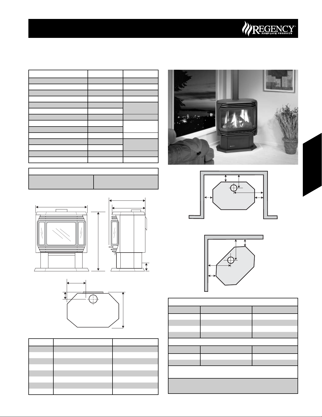
Dimension Description U38
A Top Width 26” (660mm)
B Unit Height 30” (762mm)
C Top Depth (back to front face) 17-5/8” (448mm)
D Top Depth 17” (432mm)
E Height; Base to Gas Line 3-1/2” (89mm)
F Top; Front to Back 17” (432mm)
G Depth; Flue-Centerline to Back 3-1/2” (89mm)
H Width; Side of unit to Gas Line 10-3/4” (273mm)
N
M
N
E
M
Alcove clearances
Dimension Description U38
I Side Wall to Unit 7-1/2” (190mm)
J Back Wall to Unit 6” (155mm)
K Back Wall to Vent Centerline 10-3/4” (273mm)
L Side Wall to Vent Centerline 20-1/2” (521mm)
Corner Clearances
Dimension Description U38
M Wall to Unit Corner 2” (50mm)
N Wall to Vent Centerline 11” (280mm)
Minimum ceiling height is 36" (914mm) from top of unit.
Minimum clearance to vent : According to B-Vent Manufacturer
The above listed clearances are minimum distances to combustible
materials. When installing on carpet or vinyl fl ooring the bottom pedestal
cover plate must be installed.
155June 2007 Regency Product Specifi cations Book
Page 2
U38 Gas Stove
Venting
This heater is a vented appliance and must be connected to a chimney/
fl ue in accordance with the installation codes.
Note: The rear pedestal cover plate is only required when outside
For your safety this heater is equipped with a vent safety switch designed
to sense incorrect venting and react by shutting down the gas supply.
This thermally actuated switch is located within the draft hood and
will detect either a blocked chimney or backdraft condition where the
chimney fl ow has reversed. If this switch shuts the unit down, it indicates
a drafting problem that must be identifi ed and rectifi ed without delay - the
thermally activated switch must never be bypassed or disconnected as
a hazardous or deadly condition can result.
A four inch diameter vent is required. B-Vent, Class A or Masonry
with an approved liner are all acceptable. For cosmetic or aesthetic
purposes 6" outer vent can be used as long as an approved inner vent
is installed. Fasten but do not penetrate the inner sleeve of the B-Vent
when tightening the screw.
Gas Stoves
Follow all venting manufacturer’s requirements and local building codes.
In cold climates, we recommend the use of insulated B-Vent, chase, and
liners. For altitudes above 2000 ft. we recommend that a minimum fl ue
height of 12 ft. is used.
air is being used. If using room air for combustion, remove
this plate from the back of the pedestal.
Venting Requirements
Gas Stoves
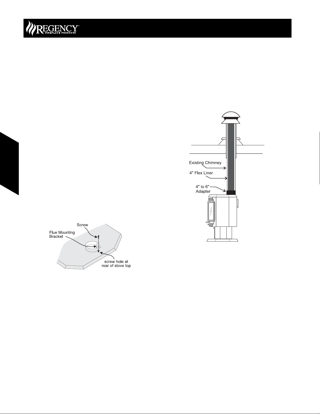
Installation into Existing
Wood Stove Flue System
1) Clean existing Chimney system.
2) Run an approved 4" fl ex liner or "B" vent into existing chimney.
Note:
See the chimney systems manufacturer for detailed
installation instructions.
Flue Mounting Bracket
Attach the fl ue mounting bracket with the enclosed screw as shown in
the diagram.
156 June 2007 Regency Product Specifi cations Book
 Loading...