

Page 1
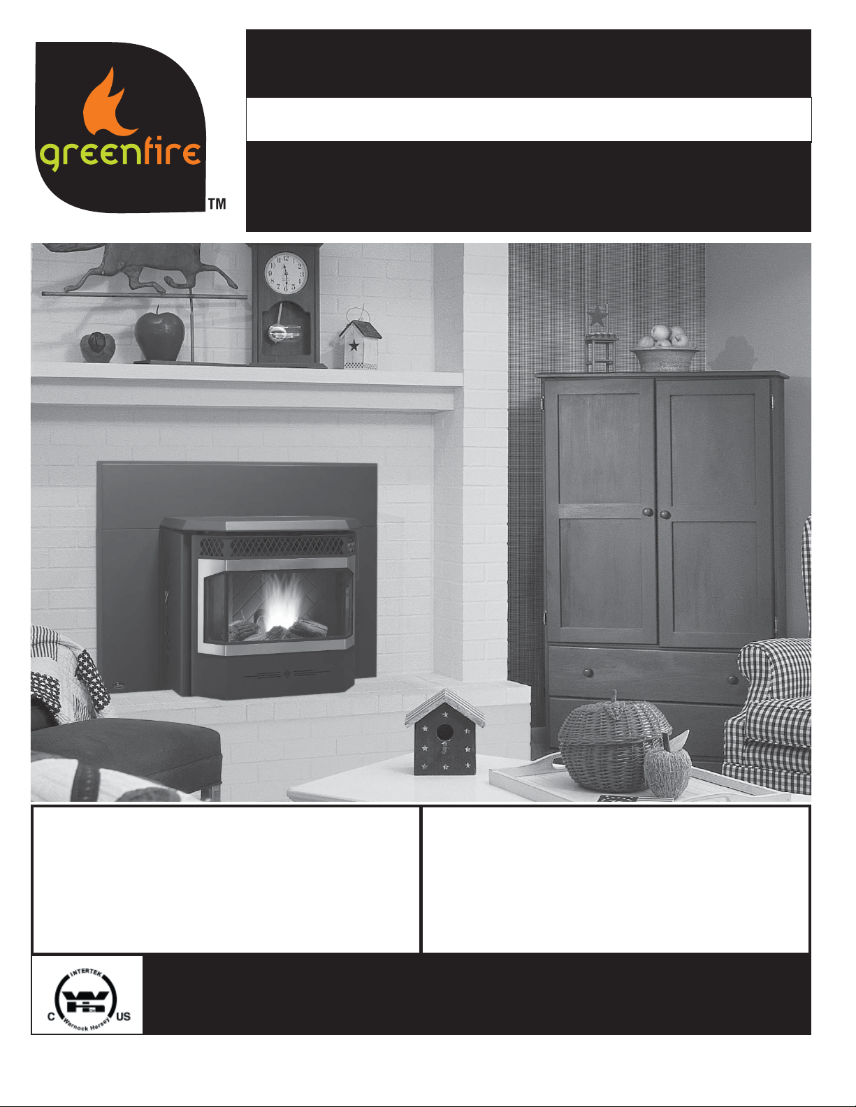
GF55 & GFI55
TECHNICAL MANUAL
Freestanding and Fireplace
Insert Pellet Stove
WARNING:
Improper installation, adjustment, alteration,
service or maintenance can cause
injury, property damage, or loss of life.
Refer to this manual. For assistance or
additional information consult an authorized
installer or service agency.
Tested by:
IMPORTANT: SAVE THESE INSTRUCTIONS
GF55-080
FPI FIREPLACE PRODUCTS INTERNATIONAL, LTD. 6988 Venture St., Delta, BC, Canada V4G 1H4
FOR YOUR SAFETY:
Do not store or use gasoline or other fl ammable
vapours and liquids in the vicinity of this or any other
appliance.
Installation and service must be performed by an
authorized installer or service agency.
06/03/08
Page 2
Safety Note: If this stove is not properly installed, a house fi re may result. For your safety,
follow the installation instructions, contact local building, fi re offi cials, or authority having jurisdiction
about restrictions and installation inspection requirements in your area.
The authority having jurisdiction should be consulted before installation to determine the need to
obtain a permit.
2
Greenfi re Pellet Stove and Insert Technical Manual
Page 3

TABLE OF CONTENTS
* This manual is designed for the technician in conjunction with the owner’s manual. *
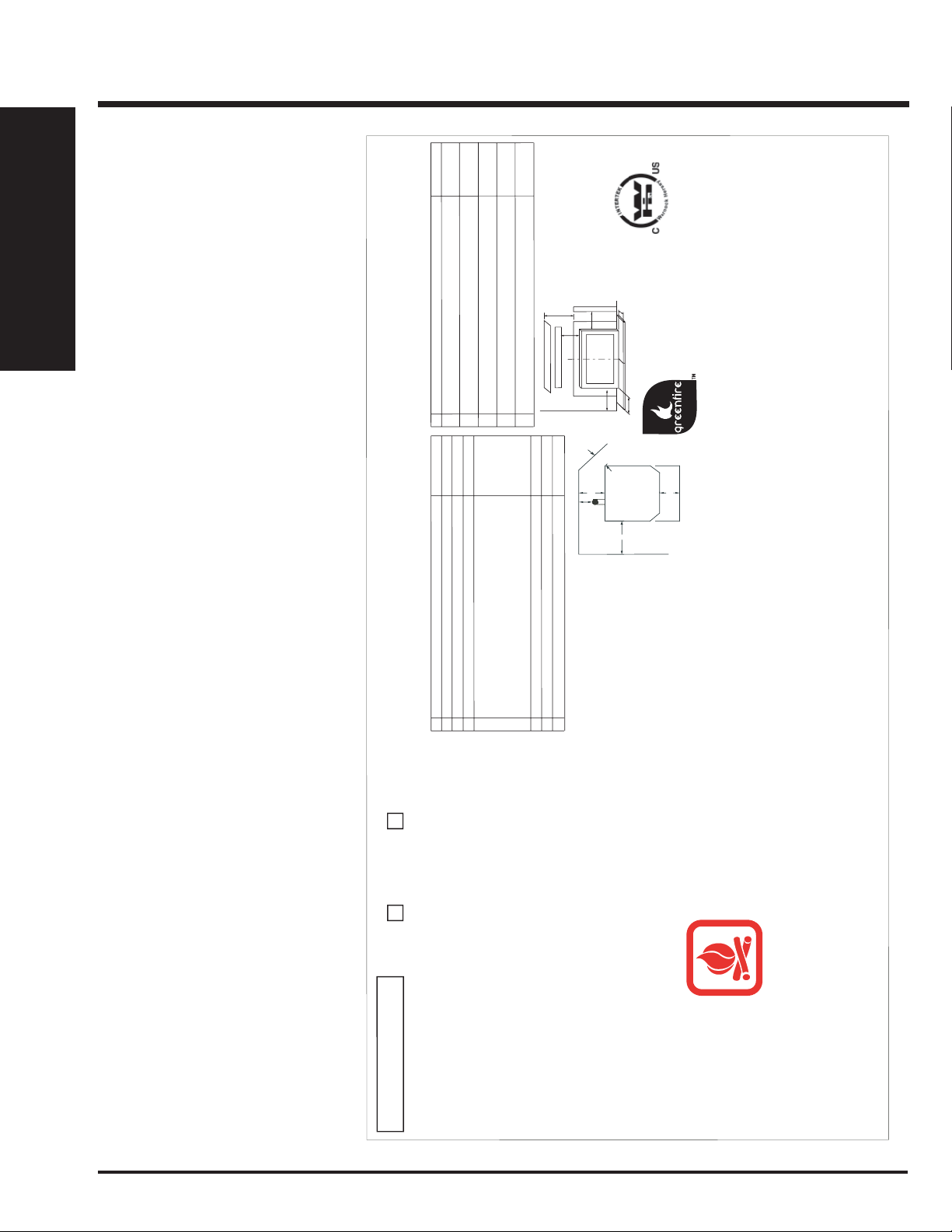
SAFETY LABEL
Copy of Serial No. Decal ...............................................4
UNIT DIMENSIONS
GF55 Freestanding Pellet Stove ...................................5
GFI55 Fireplace Pellet Insert .........................................6
INSTALLATION
Important Safety Information .........................................7
Safety Warnings & Recommendations ..........................7
Removing Pellet Stove From Pallet ...............................8
Opening the Door ..........................................................8
Locating the Pellet Appliance ........................................8
GF55 Freestanding Pellet Stove ...................................9
Clearances to Combustibles.....................................9
Alcove Clearances ....................................................9
Mobile Home Installation ..........................................9
Vent Termination Requirements .............................10
Exhaust & Fresh Air Intake Location ...................... 11
Outside Fresh Air Connection.................................11
Corner Through Wall Install ....................................11
Horizontal Exhaust Through Wall Install .................12
Vertical Rise with Horizontal Termination ...............13
Through Concrete Wall with Vertical Rise ..............13
Inside Vertical Installations .....................................13
Outside Vertical Installations ..................................14
Hearth Mount Installations ......................................14
GFI55 Pellet Insert.......................................................15
Clearances to Combustibles...................................15
Fireplace Specifi cations.......................................... 15
Pedestal & Leveling Legs .......................................15
Hopper Cover & Adjusting Hopper Height ..............15
Exhaust & Fresh Air Intake Location ......................16
Outside Fresh Air Connection.................................16
Masonry Fireplace Insert Install..............................16
Positive Flue Connection without
a Full Reline (USA only) .........................................17
Control Panel in Surround Panel ............................18
Surround Panel Installation ....................................18
Plated Door Installation ...............................................19
Thermostat Installation ................................................19
Hopper Grate Installation............................................. 20
Slider / Damper Set-Up .............................................. 20
TROUBLESHOOTING
Troubleshooting FAQ's ................................................21
Wiring Diagram ............................................................23
PARTS LIST
Parts List & Components .............................................24
Pellet Stove Components ............................................25
GF55 Freestanding Pellet Stove .................................26
GFI55 Pellet Insert.......................................................27
WARRANTY
Warranty ......................................................................28
Exclusions and Limitations ..........................................29
Greenfi re Pellet Stove and Insert Technical Manual 3
Page 4
SAFETY LABEL
To Start Stove: Press the ON / OFF button. If the auger needs to be primed, press the Manual Auger Feed button until fuel starts to drop into the Burn Pot.
To Operate Stove:
MANUAL
MODE: When a fire
has
been established
the stove settings are adjustable. / HIGH/LOW MODE: (Requires a thermostat) When
the
thermostat
calls for heat the
stove settings are adjustable.
When the thermostat contacts open, the
HEA
T
LEVEL and Fans will drop down to the LOW
setting until the thermostat contacts close again. / AUTO/OFF MODE: (Requires a thermostat) When the thermostat contacts close, the unit will light
automatically. Once up to temperature the stove settings are adjustable. When the thermostat
contacts open,
the stove will drop down to the LOW settings for
30 minutes. If within the 30 min the thermostat contacts close, the
HEA
T
LEVEL will return to previous MANUAL setting or if the thermostat contacts remain
open the stove begin its shutdown routine.
To Turn Off Stove: MANUAL and HI / LOW mode: Press the ON / OFF button
AUTO / OFF mode: Turn the thermostat down or off.
The unit
can be instal
led on a har
d,
stable non-combustible surface.
L'unité peut
être installée sur un dur, la
surface non-combustible stable.r.
Certified for use in Canada & USA
Certifié pour installation au
Canada et aux Etats-Unis.
Listed Room Heater, Pelletized Fuel Type (Appareil de chauffage à granules certifié)
Suitable For Mobile Home Installation (Accepté pour l'installation dans une maison mobile, test)
Tested to (Testée selon):
U
L
14
82-1998 /
ULC S
627-00 / ASTM 1509-95 / U LC S628-
M93
This pellet appliance has been tested and listed for use in manufactured homes in accordance with Oregon
Administration Rules 814-23-900 through 814-23-909. Install and use only in accordance with the Manufacture’s
installation and operating instructions. Contact local building or fire officials about restrictions and installation inspection in
your area. Do not connect this unit to a chimney flue serving another appliance. See local building codes and
manufacturers instructions for precautions required for passing a chimney through a combustible wall or ceiling. Electrical
rating: 120 volts, 60 hz, 4.3 Amps. Route cord away from the heater.
Cet appareil a été testé et certifié pour utilisation dans les maisons mobiles en accord avec les "Règles
Administratives de l'Oregon 814-23-900 à 814-23-909". Installez et utilisez cet appareil seulement selon les
instructions d'installation et d'opération du fabricant. Contactez les autorités locales de votre quartier concernant les
restrictions et les inspections d'installation. Consultez les codes de bâtiment locaux et les instructions du fabricant
pour les précautions à prendre lorsque une cheminée doit être installée au travers un mur ou un plafond
combustible. CLASSEMENT ÉLECTRIQUE : 120 Volts, 60 Hz, 4.1 Amps. Placez le câble électrique loin de la
chaleur.
For Use With Only Pelletized Wood fuels. Operate only with viewing door and ash removal door closed. Only replace
glass with ceramic glass. Components required for installation: a 3 inch (75 mm) or 4inch (100 mm) listed PL vent,
complete with components. Insert and Hearth mount installations; a listed single wall chimney liner may be used. Inspect
and clean Exhaust Venting system frequently.
Utilisation
avec les combustibles sous forme de boulets uniquement.
Utiliser seulement lorsque les portes avants et la
porte du réceptacle de cendre sont fermées. Si une ou des vitres devaient être remplacées, utilisez seulement du
verre céramique. Les composantes requises pour l'installation sont un évent PL certifié de 3in/75mm or 4in/100mm
avec ses composantes.
Les installations insertion et de mont de foyer ; un paquebot de cheminée de mur de seul
énuméré peut être utilisé.
Input Rating (Les données évaluant): 12,000 to 45,000 BTU/Hr (3.5 to 13.2 kWh
)
334
DATE OF MANUFACTURE /
DATE DE FABRICATION:
GF55-081 J F M A M J J A S O N D 2008 2009 2010
CAUTION:
Hot while operating. Do not
touch, severe burns may
result. Keep children, clothing,
furniture, gasoline or other
flammable vapors away
.
ATTENTION:
Très chaud quand allumé. Ne touchez pas,
les brûlures sévères peuvent résulter.
Tenez loin des enfants, des vêtements, des
meubles,de l’essence ou d’autres fluides
produisant des vapeurs inflammables.
DO NOT REMOVE THIS LABEL /
NE RETIREZ PAS CETTE ÉTIQUETTE
See installation and operating instructions accompanying appliance. /
Consultez le manuel avec les instructions d’installation et d’opération
.
A Sidewall to Unit (Du mur de côté à l'appareil)
8” (203 mm)
B Top of unit to an unshielded 8” (203 mm) mantle
(Le sommet de l'unité à un manteau de cheminée non blindé) 8” (203 mm)
C
Unit to top facing (protruding ¾” [19 mm])
(
De l'unité au sommet du parement)
8” (203 mm)
D Unit to side facing (protruding ¾” [19 mm])
(
De l'unité au côté du parement)
8” (203 mm)
E From door opening of unit to edge of floor protection
(De la porte ouvrant au devant de protection de plancher) 6”
(152 mm)
F From side of unit to edge of floor protection
(De l'ouverture
de porte pour prendre parti de protection de plancher) 6” (152 mm)
Combustible floors must be protected by a
non-combustible material.
- See Owners Manual.
Le plancher combustible doit être protégé par
un matériel incombustible.
- Consultez le manual.
INSTALLED AS A FIREPLACE INSERT STOVE MODEL (GFI55) / A INSTALLE
COMME UN MODÈLE SUR PIED DE POELE.
Minimum clearances to combustible materials./ Les dégagements minimums aux matériels
combustibles:
A Sidewall to Unit (Du mur de côté à l'appareil)
6” (152 mm)
B Backwall to Unit (Du mur de derrière à l'appareil)
3” (76 mm)
C
Corner to Unit (Du coin à l'appareil)
2” (51 mm)
D Wall to vent (Le mur pour donner vent) 3” (76 mm)
E From door opening of unit to edge of floor protection
(De la porte ouvrant au devant de protection de plancher) 6”
(
152
mm)
NOTE: A combustible floor m
us
t be protected by a
non-
c
om
bustible m
ateri
al - Width 27"
(686m
m) by depth 34"
(
864mm). (
U
n plancher
combusti
ble
doi
t etre
prote
g
e
par un
mater
i
el incombust
ible. La largeur
27" (686 m
m) par la
pr
ofondeur 34" (86
4mm).)
Minimum Alcove Width (La largeur minimum de l'alcove)
36
” (914 mm)
Minimum Alcove Height (La hauteur minimum de l'alcove) 48” (1219 mm)
Maximum Alcove Depth (La profondeur maximum de l'alcove) 30
” (762 mm)
INSTALLED AS A FREESTANDING STOVE MODEL (GF55) / A INSTALLE COMME UN
MODÈLE FS, QU’IL SOIT ENCASTRÈ, SUR PIED OU DANS UNE MAISON MOBILE.
Minimum clearances to combustible materials./ Les dégagements minimums aux matériels
combustibles:
Serial No. / No. De Serié:
Greenfire GF55 (Stove) GFI55 (Insert)
Model / Modèle:
15956
B
A
D
C
Adjacent wal
l
F
E
Floor Protection
A
B
C
E
Backwall
Sidewall
D
Pour démarrer le poêle: Appuyer sur le bouton "ON/OFF". Si le Auger nécessite d'être amorcé, appuyer sur le bouton manuel d'alimentation du Auger jusqu'à ce que les granules se déversent dans le pot de combustion.
Pour faire fonctionner le poêle
:
MODE MANUEL : Lorsque le
feu est bien établi, les réglages peuvent être ajustés. / MODE "HIGH/LOW" : (Nécessite un
thermostat)
Lorsque le thermostat
requière de la
chaleur, les réglages peuvent être ajustés. Lorsque les contacts
du
thermostat ouvrent, le réglage du niveau de chaleur et les ventilateurs s'ajusteront au réglage " bas " jusqu'à ce que les contacts du thermostat se referment. / MODE "AUTO/OFF" : (Nécessite un thermostat) Lorsque
les contacts du thermostat ferment, le poêle
s'allumera
automatiquement. Lorsque la température adéquate est atteinte, les réglages peuvent être ajustés. Lorsque les contacts du thermostat
ouvrent, le poêle s'ajustera aux réglages
"LOW" pendant 30 minutes. Si les contacts du thermostat sont fermés pendant
ces 30
minutes, le réglage de niveau de chaleur retournera en réglages "MANUEL" ou si les contacts du thermostat restent ouverts, le poêle entamera le processus d'arrêt.
Pour éteindre le poêle : MODE MANUEL
ET " HIGH/LOW " :
Appuyer sur le bouton "ON/OFF".
MODE "AUTO / OFF" : Régler le thermostat à la baisse ou éteignez le.
Manufactured in Canada for /
Fabriqué dans le Canada pour:
FPI Fireplace Products International Ltd.
Delta, BC, Canada
This is a copy of the label that accompanies each GF55 & GFI55. We have
printed a copy of the contents here for
your reference.
On the GF55 the safety label is located
on the underside of the hopper lid.
On the GFI55 the safety label is located
on the hopper cover behind the top
INSTALLATION
faceplate.
4
Greenfi re Pellet Stove and Insert Technical Manual
Page 5
9
/16"
1
(40mm)
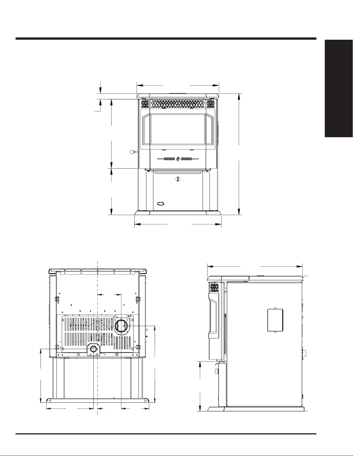
UNIT DIMENSIONS
GF55 FREESTANDING PELLET STOVE
1
23
/16"
(586mm)
7
19
/16"
(494mm)
341/8"
(866mm)
1
13
/16"
(332mm)
INSTALLATION
5
/8"
14
(356mm)
3
/4"
5
(146mm)
5
/16"
20
(508mm)
7
24
/16"
(620mm)
9
/16"
12
(319mm)
24"
(610mm)
11 7/16"
(291mm)
Greenfi re Pellet Stove and Insert Technical Manual 5
1"
(25mm)
11
/16"
6
(170mm)
Page 6
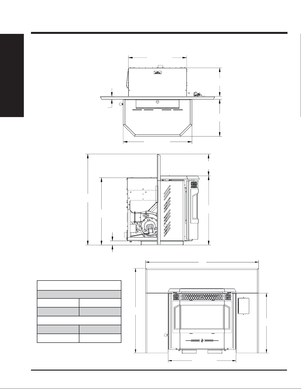
UNIT DIMENSIONS
INSTALLATION
GFI55 FIREPLACE PELLET INSERT
203/8" (517mm)
1
/16"
1
(26mm)
1
/16" (610mm)
24
10"
(253mm)
13"
(329mm)
3
/16"
30
(766mm)
225/16"
(567mm)
1
FACEPLATE DIMENSIONS
Regular Faceplate
(A) Height 30" (761mm)
3
/8" (35mm)
1
/4"
7
(183mm)
15
22
/16"
(582mm)
B
(B) Width 39-15/16" (1014mm)
Oversize Faceplate
(A) Height 33" (838mm)
(B) Width 45-15/16" (1167mm)
6
A
3
21
/16"
(538mm)
2315/16" (609mm)
Greenfi re Pellet Stove and Insert Technical Manual
Page 7

INSTALLATION
IMPORTANT SAFETY INFORMATION
Failure to follow these instructions may result
in property damage, bodily injury or even death.
Contact your local building or fi re offi cial to obtain a permit and any
information on installation restrictions and inspection requirements for
your area.
To prevent the possibility of a fi re, ensure that the appliance is properly
installed by adhering to the installation instructions. A Greenfi re dealer will
be happy to assist you in obtaining information with regards to your local
building codes and installation restrictions.
Be sure to maintain the structural integrity of the home when passing a
vent through walls, ceilings, or roofs.
The stove's exhaust system works with negative combustion chamber
pressure and a slightly positive chimney pressure. It is very important to
ensure that the exhaust system be sealed and airtight. The ash pan and
viewing door must be locked securely for proper and safe operation of
the pellet stove.
Do not burn with insuffi cient combustion air. A periodic check is recom-
mended to ensure proper combustion air is admitted to the combustion
chamber. Setting the proper combustion air is achieved by adjusting the
slider damper located on the left side of the stove. Refer to "Slider/Damper
Set-up" section.
When installing the stove in a mobile home, it must be electrically grounded
to the steel chassis of the home and bolted to the fl oor. Make sure that the
structural integrity of the home is maintained and all construction meets
local building codes.
Minor soot or creosote may accumulate when the stove is operated under
incorrect conditions such as an extremely rich burn (black tipped, lazy
orange fl ames).
If you have any questions with regard to your stove or the above-mentioned information, please feel free to contact your local dealer for further
clarifi cation and comments.
SAFETY WARNINGS &
RECOMMENDATIONS
ELECTRICAL: The use of a surge protected power bar is
recommended. The unit must be grounded. The grounded electrical
cord should be connected to a standard 115 volts (4.6 Amps), 60 hertz
electrical outlet. Be careful that the electrical cord is not trapped under
the appliance and that it is clear of any hot surfaces or sharp edges and
also must be accessible. If this power cord should become damaged,
a replacement power cord must be purchased from a Greenfi re dealer.
This unit's maximum power requirement is 520 watts.
GLASS: Do not abuse the glass by striking or slamming the door. Do not
attempt to operate the stove with broken glass. The stove uses ceramic
glass. Replacement glass must be purchased from a Greenfire dealer.
Do not attempt to open the door and clean the glass while the unit is in
operation or if glass is hot. To clean the glass, use a soft cotton cloth and
mild window cleaner, gas or wood stove glass cleaner, or take a damp
paper towel and dip into the fly ash. This is a very mild abrasive and will
not damage the glass.
FLAMMABLE LIQUIDS: Never use gasoline, gasoline-type lantern
fuel, kerosene, charcoal lighter fluid, or similar liquids to start or “freshen
up” a fire in the heater. Keep all such liquids well away from the heater
while it is in use.
SMOKE DETECTOR: Smoke detectors should be installed and
maintained in the structure when installing and operating a pellet burning
appliance.
OPERATION: The ash pan and door must be closed securely for proper
and safe operation of the pellet stove. Also ensure all gaskets on the door
are checked and replaced when necessary.
INSTALLATION: Be sure to maintain the structural integrity of your
home when passing a vent through walls, ceilings, or roofs. It is
recommended that the unit be secured into its position in order to avoid
any displacement.
DO NOT INSTALL A FLUE DAMPER IN THE EXHAUST VENTING
SYSTEM OF THIS UNIT.
DO NOT CONNECT THIS UNIT TO A CHIMNEY FLUE SERVING
ANOTHER APPLIANCE.
FRESH AIR: Outside Fresh Air connection is optional. Must be
connected to all units installed in Mobile and “Air Tight Homes” (R2000)
or where required by local codes. Consider all large air moving devices
when installing your unit and provide room air accordingly. Limited air
for combustion may result in poor performance, smoking and other side
effects of poor combustion.
INSTALLATION
CAUTION:
Do not connect to any air distribution duct or system.
Do not burn garbage or fl ammable fl uids such as gaso-
line, naptha or engine oil.
Unit hot while in operation. Keep children, clothing and
furniture away. Contact may cause skin burns.
SOOT: Operation of the stove with insuffi cient combustion air will result in
the formation of soot which will collect on the glass, the heat exchanger,
the exhaust vent system, and may stain the outside of the house. This is
a dangerous situation and is ineffi cient. Frequently check your stove and
adjust the slider/damper as needed to ensure proper combustion. See
"Slider/Damper Setting".
CLEANING: There will be some build up of fl y ash and small amounts of
creosote in the exhaust. This will vary due to the ash content of the fuel
used and the operation of the stove. It is advisable to inspect and clean
the exhaust vent semi-annually or every two tons of pellets.
Greenfi re Pellet Stove and Insert Technical Manual 7
If you have any questions with regards to your stove or the abovementioned information, please feel free to contact your Greenfire dealer
for further clarification and comments.
SINCE FPI HAS NO CONTROL OVER THE INSTALLATION OF YOUR
STOVE, FPI GRANTS NO WARRANTY IMPLIED OR STATED FOR THE
INSTALLATION OR MAINTENANCE OF YOUR STOVE. THEREFORE,
FPI ASSUMES NO RESPONSIBILITY FOR ANY CONSEQUENTIAL
DAMAGE(S).
Page 8
INSTALLATION
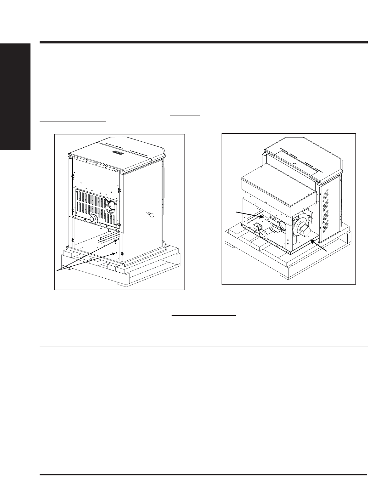
REMOVING PELLET STOVE
FROM PALLET
To remove your new stove from its pallet, remove the two (2) screws
securing the bottom to the pallet.
Freestanding:
One screw can be easily seen from behind but to access the second screw
the ashpan must be removed. See fi gure 1.
INSTALLATION
Fireplace Insert:
There is one screw on either side of the bottom. See fi gure 2.
Figure 1: Removing GF55 From Pallet.
Figure 2: Removing GFI55 From Pallet.
OPENING THE DOOR
The door lever can be found inbehind the right side of the door frame. To open the door, pivet the lever outwards and upwards until it unlocks.
LOCATING THE PELLET APPLIANCE
1. Check clearances to combustibles. See "Clearance to Combustibles"
section.
2. Do not obtain combustion air from an attic, garage or any unventilated
space if enough air is available. Combustion air may be obtained from
a ventilated crawlspace.
3. Do not install the stove in a bedroom.
4. You can vent the stove through an exterior wall behind the unit or
connect it to an existing masonry or metal chimney (must be lined if
the chimney is over 6” (15 cm) diameter, or over 28 inches² (180 cm²)
cross sectional area). An interior vent can be used with approved pipe
passing through the ceiling and roof.
5. Locate the stove in a large and open room that is centrally located in
the house. This will optimize heat circulation.
6. The power cord is 8 feet (2.43 m) long and may require a grounded
extension cord to reach the nearest electrical outlet.
8
Greenfi re Pellet Stove and Insert Technical Manual
Page 9
GF55 FREESTANDING PELLET STOVE
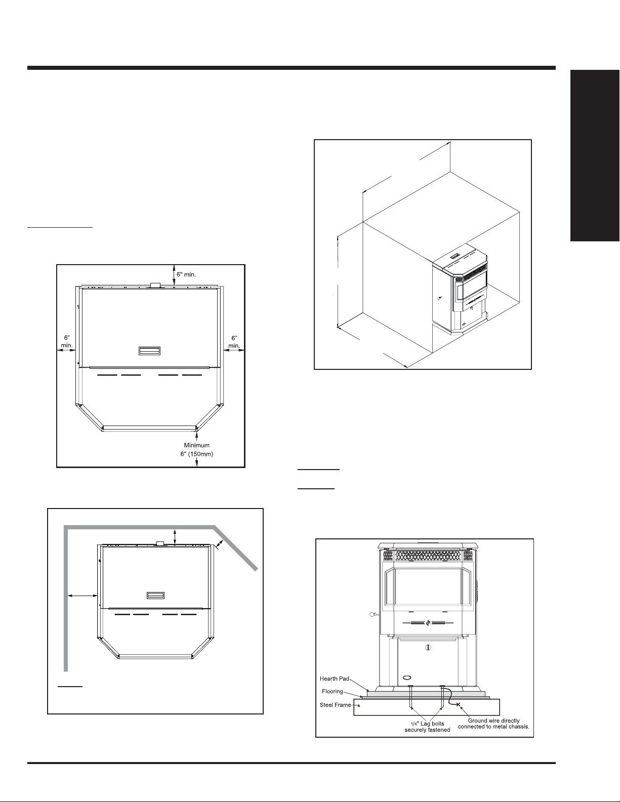
CLEARANCES TO COMBUSTIBLES
These dimensions are minimum clearances to combustibles, however it
is highly recommended that you leave suffi cient room on each side (20"
where possible) for servicing, routine cleaning and maintenance.
This pellet stove requires fl oor protection. The fl oor protection must be
non-combustible, extending 6" (150mm) beyond the full width and depth
of the unit including 6" (150 mm) in front for ember protection.
Floor Protection:
Width 36-7/16” (934mm)
Depth 36” (914mm)
Minimum Height
48" (1219mm)
INSTALLATION
ALCOVE CLEARANCES
Minimum Width
36" (914mm)
INSTALLATION
6"
Side wall
(152mm)
Figure 3: Floor Protection.
Back wall
3" (76mm)
Adjacent
2"
(51mm)*
wall
Maximum Depth
30" (762mm)
Figure 5: Alcove Clearances.
MOBILE HOME INSTALLATION
● Secure the heater to the fl oor using the holes in the pedestal of the
appliance.
● Ensure the unit is electrically grounded to the chassis of your home
(permanently).
WARNING: Do not install in a room people sleep in.
CAUTION: The structural integrity of the manufactured home fl oor,
wall and ceiling/roof must be maintained
• Outside fresh air is mandatory. Secure outside air connections directly to
fresh air intake pipe and secure with three (3) screws evenly spaced.
*NOTE: If the unit is installed as a corner installation,
clearances change from 2" to 3", see "Corner thru Wall
Installation" section.
Figure 4: Minimum Clearances to Combustibles.
Figure 6: Mobile Home Install Mounting.
Greenfi re Pellet Stove and Insert Technical Manual 9
Page 10
INSTALLATION
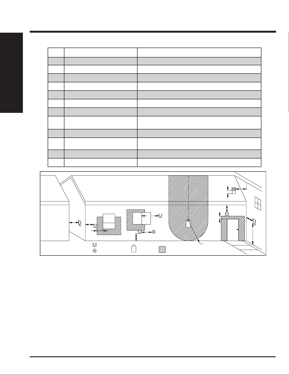
Letter Minimum Clearance Description
A 24 in (61 cm) Above grass, top of plants, wood, or any other combustible materials.
B 48 in (122 cm) From beside/below any door or window that may be opened.
C 24 in (61 cm) From above any door or window that may be opened.
D 24 in (61 cm) To any adjacent building, fences and protruding parts of the structure.
INSTALLATION
E 24 in (61 cm) Below any eave or roof overhang
F 12 in (30 cm) To outside corner.
G 12 in (30 cm) To inside corner, combustible wall (vertical and horizontal terminations).
VENT TERMINATION REQUIREMENTS
H 3 ft (91 cm) within a height of 15 ft (4.5 m)
above the meter/regulator assembly
I 3 ft (91 cm) From any forced air intake of other appliance
J 12 in (30 cm) Clearance to non-mechanical air supply inlet to building, or the combustion air
K 24 in (61 cm) Clearance above roof line for vertical terminations.
L 7 ft (2.13 m) Clearance above paved sidewalk or paved driveway located on public property.
To each side of center line extended above natural gas or propane meter/
regulator assembly or mechanical vent.
inlet to any appliance.
G
K
E
D
F
Opens
Opens
B
A
Termination Cap
Air Supply Inlet
G
B
I
Gas Meter
G
Restriction Zone
(Termination not allowed)
C
Opens
H
G
L
Figure 7: Allowable exterior vent termination locations.
1. Do not terminate the vent in any enclosed or semi-enclosed areas such as a carport, garage, attic, crawlspace, narrow walkway, closely fenced
area, under a sundeck or porch, or any location that can build up a concentration of fumes such as stairwells, covered breezeway, etc.
2. Vent surfaces can become hot enough to cause burns if touched by children. Non-combustible shielding or guards may be required.
3. Termination must exhaust above the inlet elevation. It is recommended that at least fi ve feet of vertical pipe be installed outside when the ap-
pliance is vented directly through a wall, to create some natural draft to prevent the possibility of smoke or odor during appliance shut down or
power failure. This will keep exhaust from causing a nuisance or hazard from exposing people or shrubs to high temperatures. In any case, the
safest and preferred venting method is to extend the vent through the roof vertically.
4. Distance from the bottom of the termination and grade is 12” (30 cm) minimum. This is conditional upon the plants and nature of grade surface.
The exhaust gases are hot enough to ignite grass, plants and shrubs located in the vicinity of termination. The grade surface must not be
lawn.
5. If the unit is incorrectly vented or the air to fuel mixture is out of balance, a slight discoloration of the exterior of the house might occur. Since
these factors are beyond the control of FPI, we grant no guarantee against such incidents.
NOTE: Venting terminals shall not be recessed into walls or siding.
10
Greenfi re Pellet Stove and Insert Technical Manual
Page 11

INSTALLATION
EXHAUST AND FRESH AIR INTAKE LOCATION
EXHAUST:
Base of unit to center of fl ue 20-5/16" (508mm)
Side of unit to center of fl ue 6-11/16" (170mm)
Center of unit to center of fl ue 5-3/4" (146mm)
FRESH AIR INTAKE:
Base of unit to center of intake 14-5/8" (356mm)
Side of unit to center of intake 11-7/16" (291mm)
Center of unit to center of intake 1" (25mm)
INSTALL VENT AT CLEARANCES SPECIFIED BY THE VENTING
MANUFACTURER.
3
/4"
5
(146mm)
OUTSIDE FRESH AIR CONNECTION
Outside fresh air is mandatory when installing this unit in airtight
homes and mobile homes.
A Fresh-air intake is strongly recommended for all installations.
Failure to install intake air may result in improper combustion as well as
the unit smoking during power failures.
When connecting to an outside fresh air source, do not use plastic or
combustible pipe. A 2” minimum (51 mm) ID (inside diameter) steel,
aluminum or copper pipe should be used. It is recommended, when you
are installing a fresh air system, to keep the number of bends in the pipe
to a minimum.
Outside
Wall
2" ID
(51 mm)
Optional
Elbow
INSTALLATION
5
14
/8"
(356mm)
11 7/16"
(291mm)
Figure 8: Freestanding Inlet and Outlet Location.
1"
(25mm)
11
6
/16"
(170mm)
5
/16"
20
(508mm)
Figure 9: Outside Air Connection.
CORNER THROUGH WALL INSTALLATION
Fresh Air Intake
3" (7.5 cm)
Figure 10: Corner Installation.
Wall thimble
manufactured
by pellet vent
manufacturer.
3"
(7.5 cm)
Greenfi re Pellet Stove and Insert Technical Manual 11
Page 12

INSTALLATION
HORIZONTAL EXHAUST
THROUGH WALL INSTALLATION
Vent installation: install vent at clearances specifi ed by the vent
manufacturer.
A chimney connector shall not pass through an attic or roof space, closet
or similar concealed spaces, or a fl oor, or ceiling. Where passage through
a wall or partition of combustible construction is desired, the installation
shall conform to CAN/CSA-B365 Installation Code for Solid-Fuel-Burning
Appliances and Equipment. Only use venting of L or PL type with an inside
INSTALLATION
diameter of 3 or 4 inches (7.6 or 10.1 cm).
1. Choose a location for your stove that meets the requirements stated
in this manual and allows installation with the least amount of interference to house framing, plumbing, wiring, etc.
2. Install a non-combustible hearth pad (where necessary).
3. Place the appliance 15” (37.5 cm) away from the wall. If the stove is
to be set on a hearth pad, set the unit on it.
4. Locate the center of the exhaust pipe on the stove. Extend that line to
the wall. Once you have located the center point on the wall, refer to
pellet vent manufacturer installation instructions for correct hole size
and clearance to combustibles.
5. Install the wall thimble as per the instructions written on the thimble.
Maintain an effective vapour barrier in accordance with local building
codes.
6. Install a length of 3” (76 mm) or 4” (101 mm) vent pipe into the wall
thimble. The pipe should install easily into the thimble.
7. Install the fresh air intake. See "Outside Fresh Air Connection" section.
8. Connect the exhaust vent pipe to the exhaust pipe on the stove. Seal
the connection with high temperature silicone.
Exhaust Tube
3" (75mm) or 4" (100mm)
"PL" or "L" vent
Wall Thimble
45° Elbow with screen
or Termination Cap
Fresh Air Intake
High Temperature RTV
Silicone Required
Figure 11: Straight through wall Installation.
NOTE:
• Some horizontal through wall installations may require a “T” and 3 to 5
feet (91 to 152 cm) of vertical pipe outside the building to help naturally
draft in the unit.
• This may be required if a proper burn cannot be maintained, after the
stove has been tested and the airfl ow set.
• This is due to the back pressure in the exhaust caused by airfl ow around
the structure.
• All sections of pipe must have three (3) screws evenly spaced and all
horizontal and vertical vent sections located within the house must have
a bead of high temperature silicone installed on the male end of the pipe
before installation to create a gas tight seal.
9. Push the stove straight back, leaving a minimum of 3” (8 cm) clearance from the back of the stove to the wall. Seal the vent pipe to the
thimble with high temperature silicone.
10. The pipe must extend at least 12” (30 cm) away from the building. If
necessary, bring another length of pipe (PL type) to the outside of the
home to connect to the fi rst section. Do not forget to place high tem-
perature silicone around the pipe that passes through the thimble.
11. Install a vertical pipe, or if all requirements for direct venting are met,
install vent termination. The stainless steel cap termination manufactured by the vent manufacturer is recommended. However, when the
vent terminates several feet above ground level and there are no trees,
plants, etc. within several feet, a 45° elbow can be used as termination.
The elbow must be turned down to prevent rain from entering.
12
• The termination must be 12 inches (30 cm) from the outside wall and 12
inches (30 cm) above the ground.
• A 45° elbow may be used in place of the termination cap (or stainless
steel termination hood).
Figure 12: Straight through Wall Installation - Side View.
Greenfi re Pellet Stove and Insert Technical Manual
Page 13

INSTALLATION
VERTICAL RISE WITH HORIZONTAL
TERMINATION INSTALLATION
A 45° elbow may be used in place of the termination cap (or stainless
steel termination hood).
Figure 13: Through Wall with Horizontal Termination.
INSIDE VERTICAL INSTALLATIONS
1. Choose a stove location that is ideal. Refer to "Locating Your Pellet
Appliance" section.
2. Place the unit on the hearth pad (if installed on a carpeted surface)
and space the unit in a manner so when the pellet vent is installed
vertically, it will be 3” (76 mm) away from a combustible wall.
3. Locate the center of the fresh air intake pipe on the unit. Match that
center with the same point on the wall and cut a hole about 2” (51 mm)
in diameter.
4. Install the fresh air intake pipe.
5. Install the tee with clean out.
6. Install the pellet vent upward from there. When you reach the ceiling,
make sure that the vent goes through the ceiling fi re stop. Maintain
a 3” (76 mm) distance to combustibles and keep attic insulation away
from the vent pipe. Maintain an effective vapor barrier.
7. Finally, extend the pellet vent to go through the roof fl ashing.
8. Ensure that the rain cap is at least 24” (610 mm) above the roof at the
shortest side of the vent.
Rain cap - ensure cap is at
least 2 feet (610mm) above
the roof at the lowest point
INSTALLATION
THROUGH CONCRETE WALL
WITH VERTICAL RISE INSTALLATION
A 45° elbow may be used in place of the termination cap (or stainless
steel termination hood).
This is the recommended installation to use if there is a concrete or retaining wall in line with exhaust vent on pellet stove.
The termination must be 12 inches (30 cm) from the outside wall and 12
inches (30 cm) above the ground.
Storm collar
Roof flashing
Roof rafter
Fire stop with
Support Collar
Ceiling joist
Vertical vent pipe
Clean out tee with
Pipe adapter
NOTE:
All vent sections must maintian 3"
(76 mm) clearances to combustibles.
Figure 14: Vertical rise with Horizontal Termination.
Greenfi re Pellet Stove and Insert Technical Manual 13
Figure 15: Inside Vertical Installation.
Page 14

INSTALLATION
OUTSIDE VERTICAL INSTALLATIONS
To accomplish a outside vertical pipe installation, follow steps 1 through 5
in the "Inside Vertical Installation" section and then fi nish it by performing
the following (refer to Figure 16).
1. Install a tee with clean out on the outside of the house.
2. Install PL vent upward from the tee. Make sure that you install support
brackets to keep the vent straight and secure.
INSTALLATION
3. Install ceiling thimble and secure the fl ashing as you go through the
roof.
4. Ensure that the rain cap is approximately 24” (610 mm) above the
roof.
Rain cap
24"
(61 cm)
3"
(7.5cm)
Flashing
3" (7.5 cm)
Clearance
Support
bracket
HEARTH MOUNT INSTALLATION
1. Lock fi replace damper in the open position.
2. Install a positive fl ue connector at the fi replace dampers.
3. Connect a clean-out tee or a 90° elbow to the exhaust pipe.
4. Install fl exible stainless steel liner or listed pellet vent to the top of the
chimney.
Damper Removed
or Fastened Open
Mantel
Minimum 8" (20 cm)
from top of stove
Clean-out
Fresh-air intake
should com from
chimney. If holes
lready exist fresh-air
intake can be taken
through back of the
fireplace or through
the ash dump.
Combustible FloorMasonry Fireplace
Figure 17: Hearth Mount - Side View.
Min 6"
(150 mm)
Floor
Protection
Figure 16: Outside Vertical Installation.
Type "L", "PL" or
all fuel vent
Fresh air
intake
Tee with
cleanout
14
Greenfi re Pellet Stove and Insert Technical Manual
Page 15

GFI55 PELLET INSERT
INSTALLATION
CLEARANCES TO COMBUSTIBLES
The fi replace insert is certifi ed to be installed into a masonry fi replace only
and/or zero clearance wood burning factory built fi replace where allowed
by local codes. This model includes a surround faceplate and a pedestal.
When installing this unit, ensure that the pedestal is removed from the
inside of the hopper and installed on the bottom of the unit.
From the body of the heater to the:
Side Wall 8" (203mm) minimum
Facing on Masonry Fireplace: 8" (203mm) minimum
8” (203mm) mantle: 8" (203mm) minimum
FIREPLACE SPECIFICATIONS
Your fi replace opening requires the following minimum sizes:
Height 55 lbs hopper (standard)
42 lbs hopper (adjusted)
Width 26" (660mm)
Depth 15" (381mm)
22.75" (578mm)
19.5" (495mm)
INSTALLATION OF PEDESTAL AND LEVELING LEGS
There are two parts to the GFI55 insert pedestal and they can be found
inside the hopper. Place unit on its back. Two (2) hex head screws are used
on each side of the pedestal (refer to Figure 22). Using a 5/16” wrench or
socket, secure the pedestal to the bottom of the unit.
INSTALLING HOPPER COVER AND
ADJUSTING HOPPER HEIGHT
The hopper cover initially comes upside-down on top of the hopper. To
install the hopper cover fl ip the cover over and fasten in place with four
T-20 screws (see Figure 24).
The back height of this unit can be set to one (1) of three (3) heights; 19½”
(495 mm), 21⅛” (537 mm), 22¼” (565 mm). The hopper should be set to
the maximum height that can be used in the installation.
To change the height of the hopper back up or down, remove the seven
(7) T-20 screws, three (3) on each side and one (1) on the back. The
screw placement is shown Figure 25. Move the hopper assembly to the
required setting and replace the screws. When the hopper back is in
place it is recommended that silicone is used to seal the bottom lip of the
hopper back and sides.
INSTALLATION
OPTIONAL:
There are two (2) leveling legs and they can be found inside the manual
bag. Each leveling leg consists of a long bolt, a hex nut, a washer, and a
square bolt with clip (see Figure 23). For installation of the leveling legs the
unit should be on its back and a ½” wrench is required for adjustments.
Install the square bolts into the square holes in the back corners of the
bottom. The square bolt should be inserted from inside the unit so that
the clip will be facing up.
Thread hex nut onto the bolt till it is approximately 1” (25 mm) from the
bolt head, slide washer onto bolt. Thread the bolt into the square nut so
length of the bolt shown is the approximately height needed for leveling.
When the unit is up right and the bolts can be adjusted to the exact height
required. To lock the bolts at a height tighten the hex nut and washer
against the square bolt
Leveling Legs
Figure 22: Installing Pedestal.
Figure 24: Hopper Cover Screw Placement.
Figure 25: Hopper Extension Screw Placement.
Figure 23: Square Bolt.
Greenfi re Pellet Stove and Insert Technical Manual 15
Page 16

INSTALLATION
EXHAUST AND FRESH AIR INTAKE LOCATION
EXHAUST:
Base of unit to center of fl ue 9-1/16" (229mm)
Side of unit to center of fl ue 6-1/8" (156mm)
Center of unit to center of fl ue 5-3/4" (146mm)
FRESH AIR INTAKE:
INSTALLATION
Base of unit to center of intake 3-7/16" (87mm)
Side of unit to center of intake 10-7/8" (277mm)
Center of unit to center of intake 1" (25mm)
INSTALL VENT AT CLEARANCES SPECIFIED BY THE VENTING
MANUFACTURER.
5 3/4"
(146mm)
MASONRY FIREPLACE INSERT INSTALLATION
The GFI55 requires a surround faceplate and a pedestal. When installing
this unit, ensure that the pedestal is removed from the inside of the hopper
and installed on the bottom of the unit. Refer to "Installation of Pedestal
and Leveling Legs".
Adjust hopper height - refer to "Installing Hopper Cover and Adjusting Hopper Height" and assemble surround panel. See "Installation and Removal
on Control Panel in the Surround Panel" and "Assembly and Installation
of Insert Surround Panels" before starting installation.
A non-combustible hearth pad must cover combustible fl ooring underneath,
as well as 6” (150 mm) in front of the heater and 6” (150 mm) to the side
of the heater
1. Install the hearth pad, if required.
2. Lock the fi replace damper in the open position.
3. Install a positive fl ue connector at the fi replace damper.
4. Connect a tee or 90° degree elbow to the exhaust pipe.
5. This fi replace insert must be installed with a continuous chimney liner
of 3 or 4” diameter extending from the fi replace insert to the top of the
chimney. The liner must conform to type 3 requirements of CAN/ULC
S635. For lengths below 25' use 3" and increase to 4" if longer.
6. (Recommended) Install fresh air intake either through the back of the
fi replace or through the positive fl ue connector.
1
/16"
9
7
/16"
3
(87mm)
7
10
/8"
(277mm)
Figure 26: Insert Inlet and Outlet Location.
1"
(25mm)
(156mm)
(229mm)
1
/8"
6
OUTSIDE FRESH AIR CONNECTION
Outside fresh air is mandatory when installing this unit in airtight
homes and mobile homes.
A Fresh-air intake is strongly recommended for all installations.
Failure to install intake air may result in improper combustion as well as
the unit smoking during power failures.
When connecting to an outside fresh air source, do not use plastic or
combustible pipe. A 2” minimum (51 mm) ID (inside diameter) steel,
aluminum or copper pipe should be used. It is recommended, when you
are installing a fresh air system, to keep the number of bends in the pipe
to a minimum.
Outside
Wall
2" ID
(51 mm)
Optional
Elbow
Rain Cap
Clean-out tee
If holes already exist
fresh-air intake can
be taken through the
back of the fireplace
or through the ash
dump.
Fresh-air intake
Steel Plate or Flashing
Damper Removed
or Fastened Open
Mantel (8" deep)
Masonry Fireplace
Figure 28: Installation of Fireplace Insert.
Min. 8" from
top of stove
Min. 6"
Floor
Protection
Combustible Floor
16
Figure 27: Outside Air Connection.
Greenfi re Pellet Stove and Insert Technical Manual
Page 17

INSTALLATION
When installing the insert into a masonry fi replace DO NOT remove any
bricks or masonry, with the following exception; masonry or steel, including
the damper plate, may be removed from the smoke shelf and adjacent
damper frame if necessary to accommodate a chimney liner. Provided that
their removal will not weaken the structure of the fi replace and chimney,
and will not reduce protection for combustible materials to less than that
required by the national building code.
POSITIVE FLUE CONNECTION WITHOUT A FULL RELINE
(USA ONLY)
This unit does not require a full reline (in USA only) when installing
into a masonry fi replace, however, it is recommended to ensure
proper drafting of the appliance. This type of application is not
recommended.
IMPORTANT: Ensure the chimney and fi rebox are cleaned and free of all
debris, including soot and ashes, before proceeding with this installation.
If it is not clean soot maybe blown into the room through the unit’s blower.
Ensure the fi replace and chimney have not deteriorated in any way. If
there is any sign of corrosion or damage in the chimney the unit can not
be installed. This unit can be installing in a masonry fi replace built to (UBC
37 or ULC S628 standards) or a factory built fi replace (built to UL 127 or
ULC S610 standards).
1. Install the hearth pad. The fl oor 6” (150 mm) in front of the unit and
6” (150 mm) to each side of the unit must be protected with a noncombustible hearth pad.
2. The vent connector from the insert must extend a minimum of 18”
above the chimney seal plate. The chimney seal plate area must be
sealed to prevent the exhaust from the chimney from coming back
into the fi replace and prevent air from the fi replace from entering the
chimney which will affect proper drafting of appliance.
When installing the fi replace insert into a zero clearance fi replace, where
allowed by local codes, DO NOT cut or modify any factory fi rebox parts.
If the fi replace insert does not fi t into a zero clearance fi replace we recom-
mend you use an Greenfi re freestanding model and install as a hearth
mounted unit. Install a 3” (76 mm) fl ex pipe from the stove to the top of
the chimney. Refer to "Hearth Mount Installation".
The existing chimney can
not be corroded or
damaged in any way.
Chimney must be completely
sealed with a non-combustible
material and maybe removed
Top of vent pipe
must be 18"
(45.7cm) minimum
above the chimney
seal plate.
annually for cleaning.
Mantel (8" deep)
Min. 8" from
top of stove
INSTALLATION
A qualifi ed installer should evaluate the existing fi replace to determine
the best method for achieving a positive fl ue connection between
the vent pipe or liner and the chimney. Whatever method used must
effectively seal the area to prevent room air passage to the chimney
cavity of the fi replace. A couple examples of Approved Methods of
Achieving a Positive Flue Connection are:
a) Secure a seal-off plate (i.e. 22-gage sheet steel) in the masonry
fi replace throat using masonry screws.
b) Pack non-combustible material (i.e. rockwool) around the vent pipe
or using a fl ue adapter.
3. Set leveling leg to approximate height.
IMPORTANT: The chimney seal plate must be removed for the annually
chimney cleaning as ash will build up on top of the plate.
Be aware that this type of application may have a negative effect on performance not covered under warranty.
Min. 6"
Floor Protection
Masonry Fireplace
Figure 29: Masonry fi replace positive fl ue installation.
Combustible Floor
Greenfi re Pellet Stove and Insert Technical Manual 17
Page 18

INSTALLATION
INSTALLATION AND REMOVAL OF CONTROL PANEL IN THE SURROUND PANEL
When installing the circuit board control panel into the surround panel,
the surround does not need to be assembled. The circuit board will be
found in the fi rebox.
Place the circuit board control panel on the backside of the right surround
panel so the hinge is on the outside and the top and bottom holes on the
control panel line up with those on the surround. Attach using two (2) T20 screws through the front of the surround into the circuit board control
panel (see Figure 30).
INSTALLATION
After the surround has been assembled and is ready to be installed on the
unit plug the wiring harness into the control panel (see Figure 31).
REMOVAL:
When maintenance is required on the unit the surround must be removed.
Pull the surround straight up till it stops then pull it out about 4” (10 cm)
and rest the surround on top of the unit while the control panel is removed
or disconnected.
If electrical connection is required for the maintenance remove the circuit
board control panel from the surround.
If electrical connection is not required for the maintenance remove the
wiring harness from the bottom of the circuit board control.
Figure 30: Right Panel
- Front.
Plug
Figure 31: Right Panel
- Back.
ASSEMBLY AND INSTALLATION OF INSERT SURROUND PANELS
The trim set for your surround panel must be installed before installing the
surround panel onto the unit, if not already done.
1. To assemble the surround panels, lay the panels face down on a soft
fl at surface and align the outer edges of the sides with the top panel.
Using four (4) T-20 screws up through the side panels into the top (see
Figure 32).
2. Place the assembled surround panel around the stove; align the slots
with the screw heads. Push surround in then down to engage the surround slots on the mounting screws (see Figure 33). Make sure the
top surround panel sits fl at behind the stove top.
18
Figure 33: Installed Surround Panel.
Figure 32: Assembled Surround Panel.
Greenfi re Pellet Stove and Insert Technical Manual
Page 19

INSTALLATION
PLATED DOOR INSTALLATION
TO AVOID PERSONAL INJURY DO NOT REMOVE OR REPLACE
COVER WHEN PELLET STOVE IS HOT!
TOOLS REQUIRED:
a) 11/32" socket
REMOVAL OF DOOR COVER:
When stove is off and cool, open the door. Remove the four (4) #8 hex
nuts around the inside of the glass retainer shown in Figure 37.
Remove door cover from door by gently sliding the studs out of the holes.
If it is diffi cult to remove the cover, the glass retainer may be pinching
the threads on the studs. Slightly loosen the four (4) screws (by each of
the studs).
REPLACEMENT OF DOOR COVER:
Slide new door cover into place and hand tighten the four (4) #8 hex nuts
around the inside of the glass retainer. Ensure the four screws are also hand
tight and close door. Do not overtighten or you may break screws.
Clean all plated surfaces before starting the stove. Refer to "Cleaning Plated Surfaces in Routine Cleaning and Maintenance in the Owner's
Manual.
THERMOSTAT INSTALLATION
INSTALLATION
1. Install the thermostat by connecting a low voltage millivolt thermostat to
the circuit board jumper location shown below. Connect 2 x 18 gauge
wires from the connection points on the back of the control board to
the thermostat (see fi gure 38).
2. Choose a location for the thermostat, which will effectively heat the
desired area. Do not install close to the unit, typical installation is
10ft - 20ft away in an open area (not hidden).
3. Review each of the three control switch positions with the
consumer.
Figure 38: Thermostat wire placement.
Figure 37: Inner side of door.
HOPPER GRATE INSTALLATION
Important: This grate must be installed into the hopper prior to
operating this appliance. For use on freestanding units only.
1. Open hopper door
2. Install the grate ensuring that the four fl anges on the grate is pointing
downwards into the hopper as per the diagram.
Figure 1. Flanges must face down
Figure 2. Grate installed
Greenfi re Pellet Stove and Insert Technical Manual 19
Page 20

INSTALLATION
SLIDER / DAMPER SET-UP
THE SLIDER / DAMPER MUST BE SET AT TIME OF INSTALLATION,
IT IS USED TO REGULATE THE AIRFLOW THROUGH THE PELLET
STOVE.
A Qualifi ed Service Technician or Installer must set the Slider
Damper.
The slider damper is used to regulate the airfl ow through the pellet stove
INSTALLATION
and is located behind the left cab side (refer to Figure 39). The door must
be open for the cab side to be removed on all models. On freestanding
model loosen the two T-20 torx screws, one above and one below hinge,
swing open left panel to access. On insert model remove the two (2) T-20
torx screws on the front, one above and one below hinge, and the one
T-20 at the top of the cab side under the top front.
The combustion exhaust blower is a variable speed blower controlled by
the heat output button. This blower will decrease the vacuum pressure
inside the stove and as the heat output button is turned down. The vacuum
pressure inside the fi rebox will increase as the combustion exhaust blower
increases in speed (higher heat output setting).
If the fi re should happen to go out and the heat output indicator has been
set on the lowest setting, the Slider Damper should be pushed in slightly,
decreasing the air in the fi rebox.
If, after long periods of burning, the fi re builds up and overfl ows the burn pot
or there is a build up of clinkers, this would be a sign that the pellet quality
is poor, this requires more primary air, the slider damper must be pulled out
to compensate. Pulling the slider damper out gives the fi re more air.
The easiest way to make sure that an effi cient fl ame is achieved is to
understand the characteristics of the fi re.
• A tall, lazy fl ame with dark orange tips requires more air – Open slider
(pull out) slightly.
• A short, brisk fl ame, like a blowtorch, has too much air – Close slider
(push in) slightly.
• If the fl ame is in the middle of these two characteristics with a bright yel-
low/orange, active fl ame with no black tips then the air is set for proper
operation.
Figure 40: Effi cient Flame.
have been removed in order
to see components more clearly.
Figure 39: Slider / Damper
Exhaust Blower
Exhaust
Channel
Slider
Damper
Note: Some parts
Figure 41: Hole for Pressure test with Magnehelic Gauge.
SPECIAL NOTES:
Pellet quality is a major factor in how the Pellet stove will operate. If the
pellets have a high moisture content or ash content the fi re will be less
effi cient and has a higher possibility of the fi re building up and creating
clinkers (hard ash build-up).
Taking a reading of vacuum pressure inside the fi rebox with a magnehelic
gauge can be used to set the slider for best combustion. The slider damper
should be set only on a hot stove (operating for thirty (30) minutes or more)
by placing a Magnahelic Pressure Gauge in the fi rebox. The reading can
be taken from the ⅛” (3 mm) hole located in the front of the fi rebox under
the door (see Figure 41). The best settings are a reading of approxi-
mately 0.1" to 0.12" of water column on the high fi re setting. Some
fuels may require higher or lower settings.
20
Greenfi re Pellet Stove and Insert Technical Manual
Page 21

TROUBLESHOOTING
TROUBLESHOOTING FAQ'S
DO NOT:
● Service the stove with wet hands. The stove is an electrical appliance, which may pose a shock hazard if handled improperly.
Only qualifi ed technicians should deal with possible internal electrical failures.
● Do not attempt to remove or loosen any screws from inside the fi rebox without applying penetrating oil (ie. WD40) to any of the screws.
WHAT TO DO IF:
1. The stove will not start.
2. The stove will not operate when hot.
3. The exhaust blower will not function normally.
4. Light # 2 on Heat output bar fl ashing.
5. Auger light fl ashes but auger motor does not turn at all
6. The 200 °F (93 °C) high limit temperature sensor has tripped.
7. The convection blower will not function normally.
8. Ignitor- the pellets will not light.
9. Control settings (Heat Level) has no effect on the fi re.
10. The stove keeps going out.
*NOTE: All troubleshooting procedures should be carried out by qualifi ed technicians or installers.
1. The stove will not start.
9Make sure the stove is plugged in and the wall outlet is supplying power..
9If the Control Board has been placed in the ON /OFF thermostat mode, then turn the thermostat up to call for heat.
9Ensure the burn pot liner is correctly placed in the burn pot
9Check the Heat Level Indicator. - If the # 2 light is fl ashing (see the # 2 light is fl ashing)
9Check the fuse on the circuit board.
9If the unit still does not start, contact your local service dealer for service.
TROUBLESHOOTING
2. The stove will not operate when hot.
9Check the Heat Level Indicator if a fi re is not detected, or if the fi re has gone out the #3 light will fl ash because the Exhaust Temperature Sensor’s
contacts have opened.
9Check the hopper for fuel.
9Incorrect air damper setting. - Excessive air may consume the fi re too quickly before the next drop of fuel, leaving completely unburned fuel in the
burn pot liner. - Insuffi cient air will cause build up, further restricting the air fl ow through the Burn Pot Liner. This in turn will cause the fuel to burn cold
and very slowly. Fuel may build up and smother the fi re. In this case clean the burn pot. (NOTE: unit may require a change to the vent system or
installation of fresh air to correct Air to Fuel ratio problems).
9Combustion Blower failure. - The Combustion Blower is not turning fast enough to generate the proper vacuum in the fi re box. Visual Check – is
the blower motor turning.
9Check the Exhaust Blower voltage across the blower wires (>=114 V on #5 setting and >= 82 on #1 setting). – Replace the Circuit Board if the Voltage reading is less than 82 V. with a line voltage >115 V AC.
9Check Vacuum levels in the exhaust channel by bypassing the Vacuum Switch, then remove the Vacuum hose from Vacuum Switch. Check exhaust
vacuum readings by placing the open end of the Vacuum Hose on a Magnahelic Gauge (readings must be above .10” W.C. on low fi re).
If the motor fails to reach a 0.10” W.C. readings, then replace the Combustion Blower.
9Poor Quality Fuel – Insuffi cient energy in the fuel to produce enough heat to keep the stove burning or operational.
9Exhaust Temperature Sensor failure. – Bypass sensor located on Exhaust Blower if stove now operates properly, the unit may require cleaning or
a new sensor. Contact your local dealer for service.
9Check the fuse on the circuit board.
3. The exhaust motor will not function normally.
9Open the left side access panel; check all connections against the wiring diagram.
9See “2. The stove will not operate when hot.” section.
4. Light # 2 on Heat output bar fl ashing
(The Vacuum Switch contacts have opened for more than 15 sec.)
9Pinch, break or blockage in Vacuum Hose - Check hose for pinch points or damage, replace or re-route as required. Blow out Vacuum Hose
9Blocked Hose Barb on Exhaust Channel - Use a paper clip to clean out Hose Barb or remove the Vacuum Hose from the Vacuum Switch and blow
into the hose to remove blockage.
Greenfi re Pellet Stove and Insert Technical Manual 21
Page 22

TROUBLESHOOTING
9Blocked exhaust / venting system - Have stove and venting cleaned and inspected.
9Severe negative pressure in area where unit is installed - Check the operation by opening a window, does this solve the problem? If it does, install
fresh air intake to unit or room. Venting system may require vertical section to move termination into a low pressure zone.
9Vacuum Switch failure - Bypass the vacuum switch, if this corrects the problem check for above problems before replacing the Vacuum Switch.
9Damage to gray wires between Circuit Board and Vacuum Switch - Inspect wires and connectors
9Combustion Blower failure - The Combustion Blower is not turning fast enough to generate the proper vacuum in the Exhaust Channel.
Visual Check; is the blower motor turning? Check the Exhaust Blower voltage across the blower wires (>=114 V on #5 setting and >= 82 V on #1
setting). – Replace the Circuit Board if the Voltage reading is less than 82 V. with a line voltage >114 V AC.
9Check Vacuum levels in the exhaust channel by bypassing the vacuum switch, then remove the Vacuum hose from Vacuum Switch. Check exhaust
vacuum readings by placing the open end of the Vacuum Hose on a Magnahelic Gauge. (readings must be above .10” W.C. on low fi re).
If the motor fails to reach a 0.10” W.C. readings, then replace the Combustion Blower
To reset Circuit Board after a trouble code - push the ON/OFF button
5. Auger light fl ashes but auger motor does not turn at all.
9If the Auger gear box does not turn but the motor’s armature does try to spin then the auger is jammed. – Try to break apart jam by poking at the jam
through the drop tube. If this fails then empty the hopper and remove the Auger Cover **Remember to re-seal the cover after installation**
9Check the fuse on the circuit board.
6. The 200 °F ( 93 °C) high limit temperature sensor has tripped.
9Reset sensor and determine cause – was it Convection Blower failure or 160 °F ( 71 °C) Temperature Sensor failure? Bypass the 160 °F ( 71 °C)
sensor, does the Convection blower come on high if not replace the blower? If yes, replace sensor (located on the left side of the fi rewall).
9Check the fuse on the circuit board.
7. The convection blower will not function normally.
9Clean all grill openings at the back and below unit .
9Press the fan button; does the fan come on? Press again to verify that the blower turns on; if, not contact your local dealer for service.
TROUBLESHOOTING
8. Ignitor- the pellets will not light.
9Everything else in the stove operates but the ignitor will not light the pellets.
9Make sure the burn pot liner is up tight and square to the ignitor tube by pushing the burn pot back against the ignitor tube.
9Check to see if the exhaust blower is operating. If not, contact your local dealer for service.
9Check the fuse on the circuit board.
NOTE: The ignitor should be bright orange in color. If not replace the ignitor.
9. Control settings (Heat Level) has no effect on the fi re.
NOTE: If the system light is fl ashing the Control Board has complete control of the unit. When the units system light becomes solid then control of the
unit is given back to the operator.
9If there is no control of the Heat Level button make sure the thermostat is calling for heat.
9Call your local dealer for service.
10. The stove keeps going out.
If the stove goes out and leaves fresh unburned pellets or cigarette-like ashes in the burn pot liner, the fi re is going out before the stove shuts off.
9Check to see that the Slider / Damper is in the correct position.
9Turn the Heat Level up slightly (poor quality pellets will require slightly higher settings).
9Set the auger trim till the #1 and #5 lights are illuminated.
If the stove goes out and there are partially burned pellets left in the burn pot liner, the stove has shut down due to a lack of air, exhaust temperature,
or power failure.
9Adjust the Slider / Damper.
9Check to see if the stove needs a more complete cleaning.
9Turn the Heat Level up slightly (poor quality pellets will require slightly higher settings).
9Did the power go out?
9Contact your local Dealer for service.
22
Greenfi re Pellet Stove and Insert Technical Manual
Page 23

WIRING DIAGRAM
Blue
TROUBLESHOOTING
Combustion
Blower
Convection
Temperature
Switch
N/O
Thermostat
Exhaust
Temperature
Sensor
N/O
160 °F
Purple
Black
120 °F
120 V
Grounded
Connector
Ground
Green
BlackWhite
Brown
Brown
White
Grey
Grey
White
Red
White
Yellow
Vacuum
Switch
Centre Post
Un-used
TROUBLESHOOTING
White
White
Ignitor
Auger
Motor
5 Amp
Fuse
Red
Black
Yellow
White
Blue
Brown
Brown
Purple
Grey
Grey
Orange
Orange
Connect
Thermostat
Here
Greenfi re Pellet Stove and Insert Technical Manual 23
200 °F
Convection
Blower
White
Purple
High Limit
Temperature
Switch
N/C
Page 24

PARTS LIST
PARTS LIST & COMPONENTS
Part # Description Part # Description
1) GF55-001 Auger Motor 115V 1 Rpm
2) GF55-002 Combustion Blower Motor Only 115V
3) GF55-003 Convection Blower 115V
4) GF55-004 Ignitor 300 Watt 115V
5) GF55-005 Circuit Board W/Tstat Switch 115V
GF55-006 Circuit Board Fuse (Set 2)
GF55-007 Circuit Board Wire Harness
GF55-008 Circuit Board Control Panel Decal
6) GF55-009 120 Ceramic Exhaust Temp Sensor
7) GF55-010 160 Ceramic Convection Fan Sensor
8) GF55-011 200 High Limit Sensor Manual Reset
9) GF55-012 Vacuum Switch 115V
GF55-013 Silicone Hose
GF55-014 Gasket Convection Blower Mtng
GF55-015 Gasket Combustion Blower Assembly Mtng
GF55-016 Gasket Combustion Blower Motor Mtng
GF55-017 Gasket Exhaust Starter Tube
GF55-018 Tape Window Channel 72 In.
GF55-019 Gasket 5/8 In. Door 7 Ft
GF55-020 Gasket Ped & Ash Pan 10 Ft
GF55-021 Fastener Bag Pellet Mechanical & Elec.
10) GF55-022 Burn Pot Liner SS High Ash
GF55-034 Burn Pot Liner Standard SS GF55/GFI55
GF55-023 Scraper Tool Burn Pot GF55/GFI55
GF55-025 Power Cord Domestic GF55/GFI55
GF55-026 Heyco Strain Releif
GF55-027 Sholder Bolt, Roll, Nut GF55/GFI55 2 Set
11) GF55-028 Glass Side GF55/GFI55
12) GF55-029 Glass Front GF55/GFI55
GF55-033 Exhaust Starter Tube 3x2.5 GF55/GFI55
GF55-036 Cleaning Rod Heat Tube GF55/GFI55
15) GF55-040 Door Handle GF55/GFI55
GF55-041 Door Handle Bolt, Nut, Washer GF55/GFI55
16) GF55-042 Slider Damper Rod W/Knob GF55/GFI55
GF55-046 Knob 1 in. GF55/GFI55
GF55-047 Auger Collar W/Screw 3/4 in. ID GF/GFI55
17) GF55-051 Handle Hopper Lid GF55
18) GF55-053 Latch Ash Drawer GF55
19) GF55-054 Door Control Panel W/Hinge GF55/GFI55
20) GF55-056 Brick Panel Set GF55/GFI55
21) GF55-057 Retainers Brick Panel GF55/GFI55
22) GF55-058 Cover Hopper GFI55
23) GF55-059 Lid Hopper GFI55
24) GF55-060 Ash Drawer GFI55
25) GF55-061 Lid Hopper GF55
26) GF55-062 Front Top Assembly GF55
27) GF55-066 Ash Drawer GF55
28) GF55-067 Control Panel W/Decal GF55
29) GF55-068 Main Door Complete Assembly GF55/GFI55
30) GF55-069 Front Top Assembly GFI55
31) GF55-072 Control Panel W/Decal GFI55
32) GFI55-910 Faceplate Regular GFI55
33) GFI55-912 Faceplate Oversize GFI55
34) GF55-921 Door Overlay Brush Nickel GF55 / GFI55
GF55-923 Door Overlay Antique Copper GF55 / GFI55
13) GF55-037 Burn Pot Assembly GF55/GFI55
14) GF55-038 Auger GF55/GFI55
GF55-039 Auger Brass Bushing & Plate GF55/GFI55
PARTS LIST
24
Greenfi re Pellet Stove and Insert Technical Manual
Page 25

PARTS LIST
PELLET STOVE COMPONENTS
8
3
5
14
7
6
2
1
9
PARTS LIST
Greenfi re Pellet Stove and Insert Technical Manual 25
Page 26

17
25
26
28
19
16
20
21
4
10
13
18
27
29
34
15
12
11
PARTS LIST
GF55 FREESTANDING PELLET STOVE
PARTS LIST
26
Greenfi re Pellet Stove and Insert Technical Manual
Page 27

24
32
33
31
22
23
30
GFI55 PELLET INSERT
PARTS LIST
PARTS LIST
Greenfi re Pellet Stove and Insert Technical Manual 27
Page 28

WARRANTY
FPI is the manufacturer of the Greenfi re line of heating products. At FPI, our commitment to the highest level of quality and customer
service is the most important thing we do. Each Greenfi re stove is built on a tradition of using only the fi nest materials and is backed
by our Exclusive Lifetime Limited Warranty to the original purchaser. With Greenfi re, you’re not just buying a stove, you’re buying a
company with years of unequalled performance and quality.
Limited Lifetime Warranty:
Under this warranty, FPI covers the fi replace or stove body and accessories against defects in materials and workmanship, for part
repair or replacement for the fi rst seven (7) years and limited labour for the fi rst two (2) years to the original purchaser. This Warranty
covers: Firebox, Heat Exchanger, Burn Pot, Firebox Panels, Ceramic Glass, Pedestals, Panels, Legs, Log Sets and Door Assembly.
Please see the exclusions and limitation section below as certain restrictions and exclusions apply to this warranty.
Limited Three (3) Year Warranty:
Under this warranty, FPI covers the Burn Pot Liner against defects in materials and workmanship, for part repair or replacement for
the fi rst three (3) years and limited labour for the fi rst two (2) years to the original purchaser. Please see the exclusions and limitation
section below as certain restrictions and exclusions apply to this warranty.
Limited Two (2) Year Warranty:
Under this warranty, FPI covers: Auger Motor, Circuit Board, Timers, Temp Sensors, Blowers, Vacuum Switch and Wire Harness,
against defects in materials and workmanship, for part repair or replacement for the fi rst two (2) years and limited labour for the fi rst
two (2) years to the original purchaser. Please see the exclusions and limitation section below as certain restrictions and exclusions
apply to this warranty.
Limited One (1) Year Warranty:
Under this warranty, FPI covers the Ignitor and all exterior surface fi nishes against defects in materials and workmanship, for part
repair or replacement and limited labour for the fi rst (1) year to the original purchaser. Please see the exclusions and limitation section
below as certain restrictions and exclusions apply to this warranty.
Here is how our Warranty works:
If you have any concerns with your Greenfi re product please contact the dealer where you purchased the fi replace or stove. Your
dealer shall make all claims under this warranty in writing.
To the Dealer:
When fi lling out a warranty claim please complete the following information on an offi cial warranty claim form:
Customer information: Name, address and telephone number of purchaser and date of purchase.
Dealer information: Date of installation, name of installer and dealer, serial number of the appliance, nature of complaint, defects or
malfunction, description and part numbers of any parts replaced.
To the Distributor:
Sign and verify that work and information are correct.
28
Greenfi re Pellet Stove and Insert Technical Manual
Page 29

WARRANTY
Exclusions and Limitations:
1. This Warranty does not cover tarnish, discoloration or wear on the plating or paint.
2. This Warranty excludes wear and tear or breakage caused by cleaning, moving or service on log set.
3. A qualifi ed installer must install this stove or fi replace. This Limited Warranty covers defects in materials and workmanship only if the product has
been installed in accordance with local building and fi re codes; in their absence, refer to the owner’s manual. If the product is damaged or broken
as a result of any alteration, willful abuse, mishandling, accident, neglect, or misuse of the product, the Limited Warranty does not apply.
4. The stove must be operated and maintained at all times in accordance with the instructions in the Owner’s Manual. If the unit shows signs of
neglect or misuse, it is not covered under the terms of this Warranty policy. Performance problems due to operator error will not be covered by the
Limited Warranty policy.
5. As this is a heating appliance some changes in colour of surface fi nishes may occur. This is not a fl aw and as such is not covered under this war-
ranty.
6. Some minor expansion, contraction, or movement of certain parts and resulting noise, is normal and not a defect and, therefore, is not covered
under this Limited Warranty.
7. Misuse includes over-fi ring. Over-fi ring this appliance can cause serious damage and will nullify the Limited Warranty.
8. The Limited Warranty will cover glass thermal breakage only and will not cover misuse of the stove glass, including but not limited to glass that is
struck, has surface contaminates or has had harsh or abrasive cleaners used on it.
9. This warranty does not cover products made or provided by other manufacturers and used in conjunction with the operation of this stove without
prior authorization from FPI The use of such products may nullify the Limited Warranty on this stove. If unsure as to the extent of this Limited
Warranty, contact your authorized Greenfi re dealer before installation.
10. FPI will not be responsible for inadequate performance caused by environmental conditions.
11. The Limited Warranty does not cover installation and operational related problems such as spillage caused by environmental conditions. Environmental conditions include but are not limited to nearby trees, buildings, roof tops, wind, hills, mountains, inadequate venting or ventilation, excessive
offsets, negative air pressures or other infl uences caused by mechanical systems such as furnaces, fans, clothes dryers etc.
12. The Limited Warranty is void if:
a) The stove has been operated in atmospheres contaminated by chlorine, fl uorine or other damaging chemicals.
b) The stove is subject to submersion in water or prolonged periods of dampness or condensation.
c) Any damage to the unit, combustion chamber or other components due to water, or weather damage which is the result of, but not limited to,
improper chimney/venting installation.
c) Salt air in coastal areas or high humidity can be corrosive to the fi nish; these environments can cause rusting. Damage caused by salt air or
high humidity is not covered by the Limited Warranty.
13. Exclusions to the Limited Warranty include: injury, loss of use, damage, failure to function due to accident, negligence, misuse, improper installation,
alteration or adjustment of the manufacturer’s settings of components, lack of proper and regular maintenance, alteration, or act of God.
14. The Limited Warranty does not cover damage caused to the fi replace or stove while in transit. If this occurs, do not operate the stove and contact
your courier and/or dealer.
15. The Limited Warranty does not extend to or include fi rebox paint, door or glass gaskets with damage caused by normal wear and tear, or exterior
paint discoloration or chipping, worn gaskets, etc.
16. The Limited Warranty does not include damage to the unit caused by abuse, improper installation, or modifi cation of the unit.
17. Damage to plated surfaces caused by fi ngerprints, scratches, melted items, or other external scores and residues left on the plated surfaces from
the use of abrasive cleaners or polishes is not covered in this warranty.
18. The Limited Warranty does not cover tarnish, discoloration or wear on the plated surfaces.
Greenfi re Pellet Stove and Insert Technical Manual 29
Page 30

WARRANTY
19. The paint on the Metal Brick Liner may peel. This is due to the extreme conditions applied to the paint during normal usage. It is not a fl aw and is
not covered under warranty.
20. FPI is free of liability for any damages caused by the fi replace or stove, as well as inconvenience expenses and materials. The Limited Warranty
does not cover incidental or consequential damages.
21. The Limited Warranty does not cover any loss or damage incurred by the use or removal of any component or apparatus to or from the Greenfi re
fi replace or stove without the express written permission of FPI and bearing a FPI label of approval.
22. Any statement or representation of Greenfi re products and their performance contained in Greenfi re advertising, packaging literature, or printed
material is not part of the Limited Warranty.
23. The Limited Warranty is automatically voided if the fi replace or stove’s serial number has been removed or altered in any way. If the stove is used
for commercial purposes, it is excluded from the Limited Warranty.
24. No dealer, distributor, or similar person has the authority to represent or warrant Greenfi re products beyond the terms contained within the Limited
Warranty. FPI assumes no liability for such warranties or representations.
25. FPI will not cover the cost of the removal or re-installation of the stove, hearth, facing, mantels, venting or other components.
26. Labour to replace or repair items under this Limited Warranty will be covered per our warranty service fee reimbursement schedule. Labour rates
are set per component and as such total labour costs may not be covered.
27. FPI is not liable for freight or labour on any stove replaced in-fi eld and is not liable for travel costs for service work. In the event of in-home repair
work, the customer will pay any in-home travel fees or service charges required by the Authorized Dealer.
28. At no time will FPI be liable for any consequential damages which exceed the purchase price of the unit. FPI has no obligation to enhance or modify
any stove once manufactured (example: as a stove evolves, fi eld modifi cations or upgrades will not be performed).
29. This Limited Warranty is applicable only to the original purchaser and it is non-transferable.
30. This warranty only covers Greenfi re products that are purchased through an authorized Greenfi re dealer.
31. If for any reason any section of the Limited Warranty is declared invalid, the balance of the warranty remains in effect and all other clauses shall
remain in effect.
32. The Limited Warranty is the only warranty supplied by FPI, the manufacturer of the stove. All other warranties, whether express or implied, are
hereby expressly disclaimed and purchaser’s recourse is expressly limited to the Limited Warranty.
33. FPI and its employees or representatives will not assume any damages, either directly or indirectly, caused by improper usage, operation, installation, servicing or maintenance of this stove.
34. FPI reserves the right to make changes without notice. Please complete and mail the warranty registration card and have the installer fi ll in the
installation data sheet in the back of the manual for warranty and future reference.
30
Greenfi re Pellet Stove and Insert Technical Manual
Page 31

NOTES
___________________________________________________
___________________________________________________
___________________________________________________
___________________________________________________
___________________________________________________
___________________________________________________
___________________________________________________
___________________________________________________
___________________________________________________
___________________________________________________
___________________________________________________
___________________________________________________
___________________________________________________
___________________________________________________
___________________________________________________
___________________________________________________
___________________________________________________
___________________________________________________
___________________________________________________
___________________________________________________
___________________________________________________
___________________________________________________
___________________________________________________
___________________________________________________
Greenfi re Pellet Stove and Insert Technical Manual 31
Page 32

FPI fi replaces are designed with reliability and simplicity
in mind. In addition, our internal Quality Assurance Team
carefully inspects each unit thoroughly before it leaves
our door.
FPI Fireplace Products International Ltd. is pleased to
extend this Limited Lifetime Warranty to the original
purchaser of a FPI Product.
Installer: Please complete the following information
Dealer Name & Address: ______________________________________________
___________________________________________________________________
Installer: ___________________________________________________________
Phone #: ___________________________________________________________
Date Installed: ______________________________________________________
Serial No.: __________________________________________________________
Greenfi re is a trademark of FPI Fireplace Products International Ltd.
© Copyright 2008, FPI Fireplace Products International Ltd. All rights reserved.
Printed in Canada
 Loading...