

Page 1
U31 Gas Insert
Owners &
Installation Manual
MODELS: U31-NG3 Natural Gas U31-LP3Propane
WARNING:
If the information in these instructions are not followed exactly , a fi re or explosion may result causing property damage,
personal injury or loss of life.
FOR YOUR SAFETY
Do not store or use gasoline or other fl ammable vapors and
liquids in the vicinity of this or any other appliance.
Installation and service must be performed by a qualifi ed
installer, service agency or the gas supplier.
Tested by:
Installer: Please complete the details on the back cover
and leave this manual with the homeowner.
Homeowner: Please keep these instructions for future reference.
919-099
FPI FIREPLACE PRODUCTS INTERNATIONAL LTD. 6988 Venture St., Delta, BC Canada, V4G 1H4
www.regency-fi re.com
FOR YOUR SAFETY
What to do if you smell gas:
Do not try to light any appliance
Do not touch any electrical switch:
do not use any phone in your building.
Immediately call your gas supplier
from a neighbour's phone. Follow
the gas supplier's instructions.
If you cannot reach your gas
supplier, call the fi re department.
10/17/12
Page 2
FPI GAS
FIREPLACE INSERT
TO THE NEW OWNER
Congratulations! You are the owner of a state-of-the-art Gas Insert by FPI.
The FPI Gas Insert Series of hand crafted appliances has been designed to provide you
with all the warmth and charm of a fi replace, at the fl ick of a switch. The models U31-NG3
and U31-LP3 of this series have been approved by Warnock Hersey for both safety and effi ciency. As it also bears our own mark, it promises to provide you with economy, comfort
and security for many trouble free years to follow. Please take a moment now to acquaint
yourself with these instructions and the many features of your FPI Fireplace.
2
Regency U31-3 Gas Fireplace Insert
Page 3
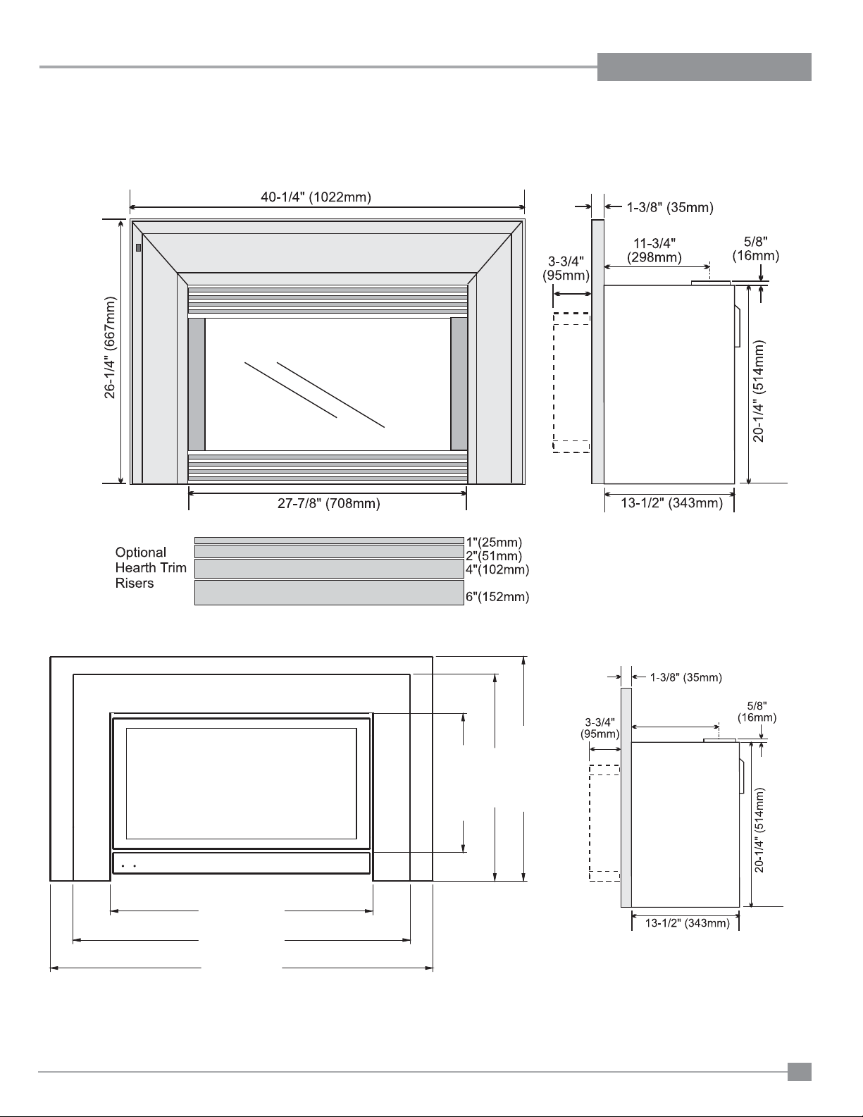
DIMENSIONS
Note: Oversize faceplate is 44" x 28" (1118 mm x 711mm)
22 (559mm)
14-7/8 (378mm)
27-15/16 (710mm)
35-15/16 (912mm)
40-3/4 (1036mm)
23-15/16 (607mm)
Low Profi le Faceplate Dimensions
10-7/8”
(276mm)
* Standard size shown, custom size also available.
Regency U31-3 Gas Fireplace Insert
3
Page 4

TABLE OF CONTENTS
Unit Dimensions ........................................................3
Safety Label...............................................................5
INSTALLATION
For Your Safety ..........................................................7
Specifi cations ............................................................8
Installation into a Solid Fuel Fireplace .......................8
General Safety Information........................................8
Installation Checklist ..................................................9
Materials Required ...................................................9
Minimum Fireplace Clearances .................................9
Clearances to Combustibles......................................9
Conversion to Propane Kit.......................................10
Gas Connection .......................................................10
High Elevation .........................................................10
Draft Hood Connection ............................................10
Venting .............................................................11
Combustion & Ventilation ..................................11
Gas Pressure Test ...................................................11
Gas Insert Aeration System .....................................11
Test for Flue Spillage ...............................................11
Optional Brick Panel ...............................................12
Log Installation ........................................................13
Faceplate & Trim .....................................................16
Glass Front Installation
Standard Flush Door (1 panel) ..........................16
Flush Louvers ...................................................17
Wiring Diagram ........................................................18
Full Screen Front .....................................................19
Excalibur Surround ..................................................20
Low Profi le Faceplate Installation............................22
Optional Wall Thermostat ........................................27
Optional Remote Control ........................................27
Final Check .............................................................27
OPERATING INSTRUCTIONS
Operating Instructions .............................................24
Lighting Procedure ..................................................24
Shutdown Procedure ...............................................25
First Fire .............................................................25
Automatic Convection Fan Operation......................25
Normal Operating Sounds of Gas Appliances .........25
Copy of Lighting Instruction Plate ............................27
MAINTENANCE
Maintenance ............................................................26
Gold Plated Trim ...............................................26
Log Replacement ..............................................26
Glass Gasket ....................................................26
Door Glass Replacement ..................................27
Flush Glass Replacement .................................27
Fan Maintenance .....................................................27
PARTS
Parts List .............................................................28
WARRANTY
Warranty .............................................................35
4
Regency U31-3 Gas Fireplace Insert
Page 5
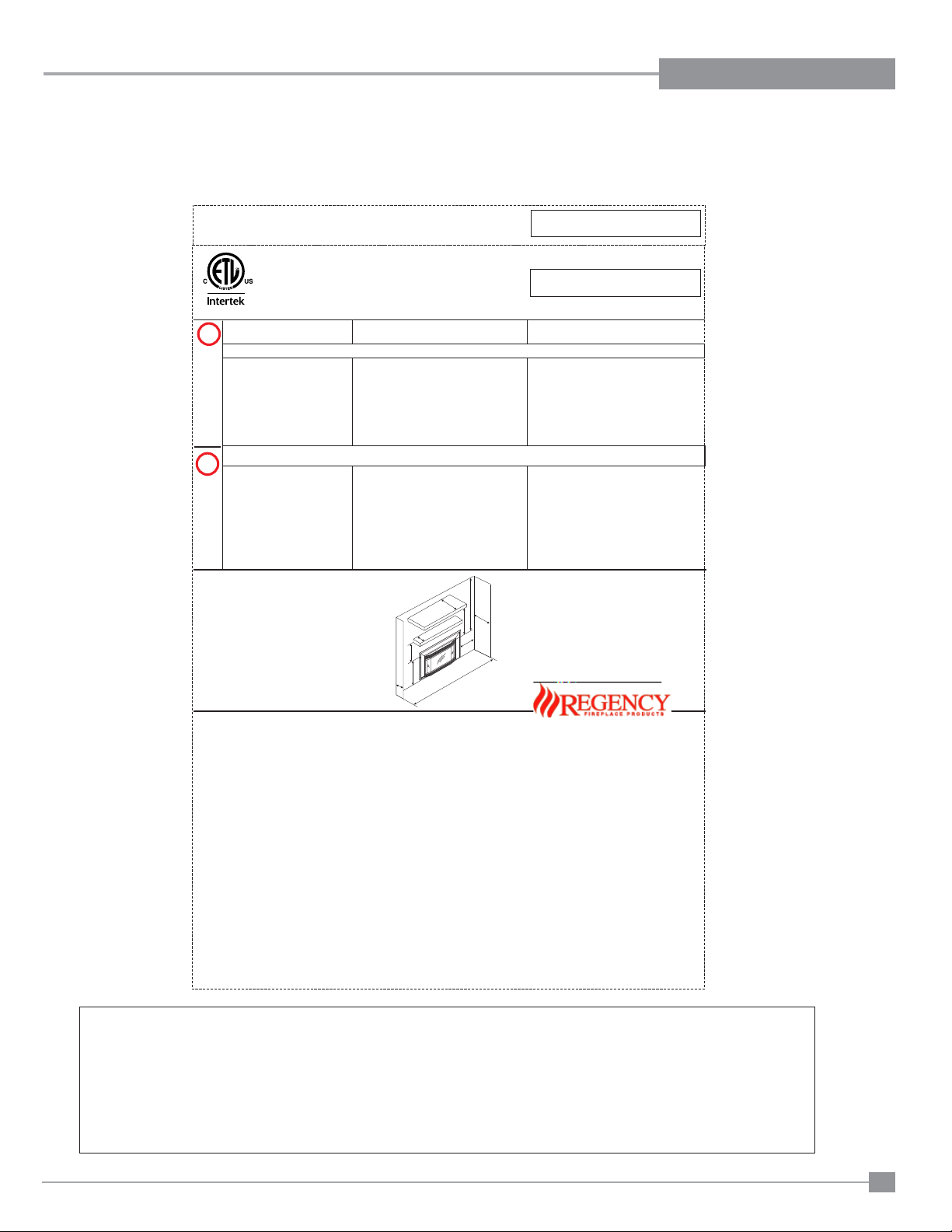
This is a copy of the labels that accompany
DO NOT REMOVE THIS LABEL /
NE PAS ENLEVER CETTE ETIQUETTE
Serial No. / No de serie
400
400
Min. supply pressure 5" WC (1.25kPa)
Low Setting Man. pressure 1.6" WC (0.40kPa)
Max. Manifold pressure 3.5" WC (0.87kPa)
Orifice size 37 DMS (2.64mm)
Minimum input 20,600 Btu/h (6.04kW)
Altitude 0-2000ft (0-610m)
Maximum input 30,000 Btu/h (8.79kW)
Use Conversion Kit (Part #400-970)
Min. supply pressure 5" WC (1.25 kPa)
Low Setting Man. pressure 1.6" WC
Max. Manifold pressure 3.5" WC
Orifice size 40 DMS (2.49 mm)
Minimum input 19,200 Btu/h (5.62kW)
Altitude 2000-4500ft (610-1370m)
Maximum input 27,200 Btu/h (7.97kW)
(0.40kPa)
(0.87kPa)
919-098
Mantel Clearances in Masonry
Fireplace Installation
NATURAL GAS FIREPLACE INSERT:
MODEL U31-NG3
PROPANE FIREPLACE INSERT:
MODEL U31-LP3
1
12" WC (2.99 kPa)
6.4" WC (1.59 kPa)
10" WC (2.49 kPa)
52 DMS (1.6mm)
22,000 Btu/h (6.45kW)
0-2000ft (0-610m)
28,000 Btu/h (8.21kW)
2" WC (2.99 kPa)
53 DMS (1.5mm)
20,000 Btu/h (5.86 kW)
2000-4500ft (610-1370m)
25,000 Btu/h (7.33 kW)
Use Conversion Kit (Part #400-971)
6.4" WC (1.59 kPa)
10" WC (2.49 kPa)
FPI Fireplace Products International Ltd.
Delta BC, CANADA
MADE IN CANADA / FABRIQUE AU CANADA
Model: U31-NG3
Model: U31-LP3
Factory Equipped For Altitude 0-2000ft. (0-610m)
Field Convertible For Altitude 2000-4500ft.(610-1370m)
Duplicate Serial number
K
L
A
B
O
N
P
Q
M
R
This appliance must be installed in accordance with local codes, if any; if none, follow the National Fuel Gas Code, ANSI Z223.1, or
Natural Gas and Propane Installation Code, CSA B149.1.
This appliancemust beinstalled in accordance withthe Standard CAN/CSAZ240 MH,Mobile Housing, in Canada,or with the Manufactured
Home Construction and Safety Standard, Title 24 CFR, Part 3280, in the United States, or when such a standard is not applicable,
ANSI/NCSBCS A225.1/NFPA 501A, Manufactured Home Installations Standard or ANSI A119.2 ou NFPA 501C Standard for Recreational
Vehicles
This appliance is onlyfor use with the type of gasindicated on the rating plate and maybe installed in an aftermarket, permanently located,
manufactured (mobile)home wherenot prohibited bylocal codes.See owner's manualfor details.
WARNING.This fireplace hasbeen convertedfor use witha gasfireplace insert onlyand cannotbe used forburning woodor solid fuelsunless
all originalparts havebeen replaced, andthe fireplacere-approved by theauthority havingjurisdiction.
Installer l'appareil selon les codes ou règlements locaux, ou, en l'absence de tels règlements, selon les codes d'installation ANSI Z223.1,
National FuelGas Codeou CSA-B149.1 envigueur.
Installer l'appareilselon la normeCAN/CSA-Z240, Série MM,Maison mobilesou CAN/CSA-Z240 VC,Véhicules de camping,ou la norme24
CFR Part 3280, Manufactured Home Construction and Safety Standard. Si ces normes ne sont pas pertinentes, utilisez la norme
ANSI/NCSBCS A225.1/NFPA 501A, Manufactured HomeInstallations Standard, ouANSI A119.2ou NFPA 501C Standard for Recreational
Vehicles.
AVERTISSEMENT : Ce foyer a été converti pour utilisation avec un foyer au gaz encastrable et ne peut être utiliser pour brûler du bois ou
d'autres combustibles solides àmoins que toutes les pièces d'origine aientété remplacées et que le foyer aitété approuvé de nouveau par
l'autorité compétente.
For usewith glassdoors certified withthe applianceonly
This ventedgas fireplaceheater is notfor usewith air filters. Ne pasutiliser de filtreà airavec ce foyerau gazà évacuation.
Cet appareildoit êtreutilize uniquement avecle typede gaz indiquésur laplaque signalétique. Cetappareil peutêtre installé dansune maison
préfabriquée oumobile (É.-U.seulement) installée àdemeure si les règlementslocaux lepermettent. Voirla notice del'utilisateur pourplus de
renseignements. Cetappareil nepeut pas êtreutilisé avecd'autres gaz saufsi unetrousse de conversioncertifiée estfournie.
Pour utilisationuniquement avecles portes enverre certifiéesavec l'appareil
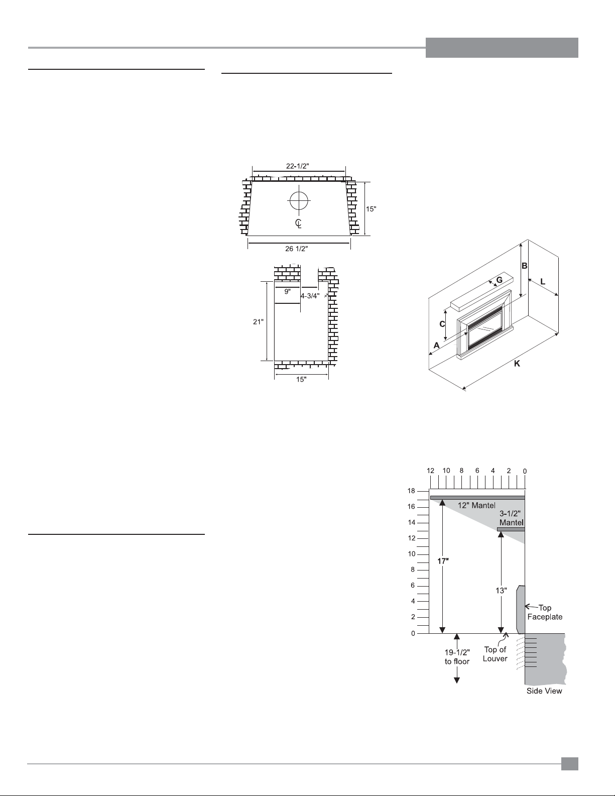
Minimum Clearances to Combustibles from Insert
Side wall A 10"(255mm)
Ceiling B 47-1/2"(1205mm)
Alcove Width K 48"(1220mm)
Max. Alcove Depth L 36"(915mm)
NOTE: for Zero Clearance Kit clearances to
Combustibles. See manual for details.
Max. Mantel depth M 12"(305mm)
Mantel height N 17"(432mm)
Mantel depth O 3-1/2"(89mm)
Mantel height P 13"(330mm)
Floor Q 19-1/2"(495mm)
Mantel Clearances in Zero Clearance
Kit Installations
Max. Mantel depth M 12"(305mm)
Mantel height N 22"(432mm)
Listed:
Certified for/Certifi e pour:
Tested to:
CANADA and U.S.A.
VENTED GAS FIREPLACE HEATER
/
Tested to:
FOYER AU GAZ À ÉVACUATION
é
CAN/CGA-2.17-M91(R2009)
ANSI Z21.88-2009/CSA 2.33-2009
Electrical supply / Électrique 115VAC, 2.5 A, 60Hz, Less than 10A Fan Part # 911-071
VENTED GAS FIREPLACE HEATER - NOT FOR USE WITH SOLID FUELS. /
NE PAS UTILISER AVEC DUCOMBUSTIBLE SOLIDE.
FOYER AU
GAZ À ÉVACUATION -
4001172
each U31-3Gas Insert. We have printed a copy
of the contents here for your review. The safety
label is located on a plate inside the base of the
unit visible when the bottom louver is opened.
NOTE: FPI units are constantly being im-
proved. Check the label on the unit
and if there is a difference, the label
on the unit is the correct one.
Regency U31-3 Gas Fireplace Insert
For the State of Massachusetts, installation and repair must be done by a plumber or gasfi tter licensed in the Commonwealth of
Massachusetts.
For the State of Massachusetts, fl exible connectors shall not exceed 36 inches in length.
For the State of Massachusetts, the appliances individual manual shut-off must be a t-handle type valve.
The State of Massachusetts requires the installation of a carbon monoxide alarm in accordance with NFPA 720 and a CO alarm
with battery back up in the same room where the gas appliance is installed.
5
Page 6

REQUIREMENTS
5.08: Modifications to NFPA-54, Chapter 10
(2) Revise 10.8.3 by adding the following additional requirements:
(a) For all side wall horizontally vented gas fueled equipment installed in every dwelling, building or structure used in whole or in part for
residential purposes, including those owned or operated by the Commonwealth and where the side wall exhaust vent termination is less than
seven (7) feet above finished grade in the area of the venting, including but not limited to decks and porches, the following requirements shall
be satisfied:
1. INSTALLATION OF CARBON MONOXIDE DETECTORS. At the time of installation of the side wall horizontal vented gas fueled
equipment, the installing plumber or gasfitter shall observe that a hard wired carbon monoxide detector with an alarm and battery back-up is
installed on the floor level where the gas equipment is to be installed. In addition, the installing plumber or gasfitter shall observe that a battery
operated or hard wired carbon monoxide detector with an alarm is installed on each additional level of the dwelling, building or structure
served by the side wall horizontal vented gas fueled equipment. It shall be the responsibility of the property owner to secure the services of
qualified licensed professionals for the installation of hard wired carbon monoxide detectors
a. In the event that the side wall horizontally vented gas fueled equipment is installed in a crawl space or an attic, the hard wired carbon
monoxide detector with alarm and battery back-up may be installed on the next adjacent floor level.
b. In the event that the requirements of this subdivision can not be met at the time of completion of installation, the owner shall have a period of
thirty (30) days to comply with the above requirements; provided, however, that during said thirty (30) day period, a battery operated carbon
monoxide detector with an alarm shall be installed.
2. APPROVED CARBON MONOXIDE DETECTORS. Each carbon monoxide detector as required in accordance with the above provisions
shall comply with NFPA 720 and be ANSI/UL 2034 listed and IAS certified.
MA Code - CO Detector
(for the State of Massachusetts only)
3. SIGNAGE. A metal or plastic identification plate shall be permanently mounted to the exterior of the building at a minimum height of eight
(8) feet above grade directly in line with the exhaust vent terminal for the horizontally vented gas fueled heating appliance or equipment. The
sign shall read, in print size no less than one-half (1/2) inch in size, "GAS VENT DIRECTLY BELOW. KEEP CLEAR OF ALL
OBSTRUCTIONS".
4. INSPECTION. The state or local gas inspector of the side wall horizontally vented gas fueled equipment shall not approve the installation
unless, upon inspection, the inspector observes carbon monoxide detectors and signage installed in accordance with the provisions of 248 CMR
5.08(2)(a)1 through 4.
(b) EXEMPTIONS: The following equipment is exempt from 248 CMR 5.08(2)(a)1 through 4:
1. The equipment listed in Chapter 10 entitled "Equipment Not Required To Be Vented" in the most current edition of NFPA 54 as adopted by
the Board; and
2. Product Approved side wall horizontally vented gas fueled equipment installed in a room or structure separate from the dwelling, building or
structure used in whole or in part for residential purposes.
(c) MANUFACTURER REQUIREMENTS - GAS EQUIPMENT VENTING SYSTEM PROVIDED. When the manufacturer of Product
Approved side wall horizontally vented gas equipment provides a venting system design or venting system components with the equipment, the
instructions provided by the manufacturer for installation of the equipment and the venting system shall include:
1. Detailed instructions for the installation of the venting system design or the venting system components; and
2. A complete parts list for the venting system design or venting system.
(d) MANUFACTURER REQUIREMENTS - GAS EQUIPMENT VENTING SYSTEM NOT PROVIDED. When the manufacturer of a
Product Approved side wall horizontally vented gas fueled equipment does not provide the parts for venting the flue gases, but identifies
"special venting systems", the following requirements shall be satisfied by the manufacturer:
1. The referenced "special venting system" instructions shall be included with the appliance or equipment installation instructions; and
2. The "special venting systems" shall be Product Approved by the Board, and the instructions for that system shall include a parts list and
detailed installation instructions.
(e) A copy of all installation instructions for all Product Approved side wall horizontally vented gas fueled equipment, all venting instructions,
all parts lists for venting instructions, and/or all venting design instructions shall remain with the appliance or equipment at the completion of
the installation.
6
Regency U31-3 Gas Fireplace Insert
Page 7

INSTALLATION
FOR YOUR SAFETY
This appliance requires air for proper combustion.
Always provide adequate combustion and
ventilation air. Follow instructions and information
in CSA B149.1 (in Canada) or the National Fuel Gas
Code ANS Z223.1/NFPA (in the USA), regarding
requirements for combustion and ventilation air.
INSTALLATION AND REPAIR SHOULD
BE DONE BY AN AUTHORIZED
SERVICE PERSON. THE APPLIANCE
SHOULD BE INSPECTED BEFORE
USE AND AT LEAST ANNUALLY BY A
PROFESSIONAL SERVICE PERSON.
MORE FREQUENT CLEANING MAY
BE REQUIRED DUE TO EXCESSIVE
LINT FROM CARPETING, BEDDING
MATERIAL, ETC. IT IS IMPERATIVE THAT
CONTROL COMPARTMENTS, BURNERS
AND CIRCULATING AIR PASSAGEWAYS
OF THE APPLIANCE BE KEPT CLEAN.
DUE TO HIGH TEMPERATURES, THE
APPLIANCE SHOULD BE LOCATED
OUT OF TRAFFIC AND AWAY FROM
FURNITURE AND DRAPERIES.
YOUNG CHILDREN SHOULD BE CAREFULLY SUPERVISED WHEN THEY ARE
IN THE SAME AREA AS THE APPLIANCE. TODDLERS, YOUNG CHILDREN
AND OTHERS MAY BE SUSCEPTIBLE
TO ACCIDENTAL CONTACT BURNS. A
PHYSICAL BARRIERS IS RECOMMENDED IF THERE ARE AT RISK INDIVIDUAL
IN THE HOUSE. TO RESTRICT ACCESS
TO A FIREPLACE OR STOVE, INSTALL
AN ADJUSTABLE SAFETY GATE TO
KEEP TODDLERS, YOUNG CHILDREN
AND OTHER AT RISK INDIVIDUALS OUT
OF THE ROOM AND AWAY FROM HOT
SURFACES.
CLOTHING OR OTHER FLAMMABLE
MATERIAL SHOULD NOT BE PLACED
ON OR NEAR THE APPLIANCE.
WARNING: FAILURE TO INSTALL THIS
APPLIANCE CORRECTLY WILL VOID
YOUR WARRANTY AND MAY CAUSE A
SERIOUS HOUSE FIRE.
CHILDREN AND ADULTS SHOULD BE
ALERTED TO THE HAZARDS OF HIGH
SURFACE TEMPERATURES, ESPECIALLY THE FIREPLACE GLASS, AND
SHOULD STAY AWAY TO AVOID BURNS
OR CLOTHING IGNITION.
Regency U31-3 Gas Fireplace Insert
7
Page 8

INSTALLATION
IMPORTANT:
SAVE THESE
INSTRUCTIONS
The Regency Gas Insert must be installed in
accordance with these instructions. Carefully
read all the instructions in this manual fi rst.
Consult the building authority having jurisdiction to determine the need for a permit prior to
starting the installation.
NOTE: Failure to follow the instructions
could cause a malfunction of the
heater which could result in death,
serious bodily injury, and/or property damage. Failure to follow these
instructions may also void your fi re
insurance and/or warranty. This appliance can be used with a thermostat.
FOR YOUR SAFETY
This appliance requires air for proper combustion. Always provide adequate combustion
and ventilation air. Follow instructions and
information in CAN/CGA B149 (in Canada) or
the National Fuel Gas Code ANSI Z223.1 (in the
USA), regarding requirements for combustion
and ventilation air.
SPECIFICATIONS
At pressures over 1/2 psig, the pipe to the unit
must be disconnected.
Gas Input Capacity:
Natural Gas 30,000 Btu/h
Propane 28,000 Btu/h
Fuels: Approved for use with both natural
gas, and propane. Approved as is for use at
0' to 2,000'. With a fi eld installed conversion
kit 0' - 4,500'.
Electrical: 120V A.C. system.
Circulation Fan: Variable speed, 127 CFM.
Log Set: Ceramic fi bre, 7 per set.
Vent System: Minimum 4" B-Vent or listed
gas fuel vent liner.
GAS PRESSURE TESTING
The appliance must be isolated from the gas
supply piping system by closing its individual
manual shut off valve during any pressure
testing of the gas supply piping system at test
pressures equal to or less than 1/2 psig. (3.45
kPa). Disconnect piping from valve at test pressures over 1/2 psig (3.45 kPa).
POLICY FOR SOLID FUEL
BURNING AND FACTOR Y
BUILT
FIREPLACES
The FPI U31-3 may be installed and vented into
any solid fuel fi replace that has been installed
in accordance with the National, Provincial and
local building codes and is constructed of noncombustible materials.
1) Installer must mechanically attach the supplied
label to the inside of the fi rebox of the fi replace
into which the gas fi replace insert is installed.
WARNING: This fi replace has been con-
verted for use with a gas fi replace insert
only and cannot be used for burning wood
or solid fuels unless all original parts have
been replaced, and the fi replace re-ap-
proved by the authority having jurisdiction.
2) Do not cut any sheet-metal parts of the fi replace,
in which the gas fi replace insert is to be installed.
3) If the factory-built fi replace has no gas access
hole(s) provided, an access hole of 1-1/2"
(37.5mm) or less may be drilled though the lower
sides or bottom of the fi rebox in a proper work-
manship like manner. This access hole must be
plugged with a non-combustible insulation after
the gas supply line has been installed.
4) The fi replace fl ue damper can be fully blocked
open or removed for installation of the gas
fi replace insert.
5) The fi replace and fi replace chimney must be
clean and in good working order and constructed
of non-combustible materials.
6) The chimney cleanouts must fi t properly.
7) Refractory (fi rebricks), glass doors, screen rails,
screen mesh and log grates can be removed
from the fi replace before installing the gas
fi replace insert.
8) Smoke shelves, shields and baffl es may be
removed if attached by mechanical fasteners.
If any part is removed it must not weaken the
structural integrity of the factory built.
9) Trim panels or surrounds shall not seal ventilation openings in the fi replace.
BEFORE YOU ST ART
Safe installation and operation of this appliance
requires common sense, however, we are required
by the Canadian Safety Standards and ANSI Standards to make you aware of the following:
General Safety Information
1) The appliance installation must conform with
local codes or in the absence of local codes,
with CAN/CGA B149 (in Canada) or the
National Fuel Gas Code ANSI Z223.1. This
appliance should be installed by a qualifi ed
gas fi tter technician only.
2) Installation and repair should be done by a
qualifi ed service person.
3) The appliance should be inspected before use
and at least annually by a professional service
person. More frequent cleaning may be required
due to excessive lint from carpeting, bedding
material, animal hair, etc. It is imperative that
control compartments, burners and circulating
air passageways of the appliance be kept clean.
4) See general construction and assembly instructions. This appliance may only be installed in a
vented, noncombustible fi replace.
5) This appliance is Listed for bedroom installations. In Canada room heaters must be installed
with a Listed Millivolt Thermostat. Some areas
may have further requirements, check local
codes before installation.
6) This unit is not approved for installation into a
mobile home.
7) Always connect this insert to a vent system
venting to the outside of the building envelope.
Never vent to another room or inside a building.
Make sure that the vent is properly sized and is
of adequate height to provide the proper draft.
8) Inspect the venting system annually for blockage
and any signs of deterioration.
9) Any glass removed for servicing must be replaced prior to operating the appliance.
10) To prevent injury, do not allow anyone who is
unfamiliar with the operation to use the fi replace.
11) Failure to position the parts in accordance with
the diagrams in this manual or failure to use only
parts specifi cally approved with this appliance
may result in property damage or personal injury.
12) Due to high temperatures, the appliance should
be located out of high traffi c areas and away
from furniture and draperies. Children and
adults should be alerted to the hazards of high
surface temperatures, especially the fi replace
glass and gold trims, and should stay away to
avoid burns or clothing ignition. Y oung children
should be carefully supervised when they are
in the same room as the appliance. Clothing or
other fl ammable material should not be placed
on or near the appliance.
Emissions from burning wood or gas could
contain chemicals known to the State of
California to cause cancer, birth defects or
other reproductive harm.
8
Regency U31-3 Gas Fireplace Insert
Page 9
INSTALLATION
INSTALLATION
CHECKLIST
The Regency Gas Insert is installed as listed below.
1) Unit Location - check Clearances to Combustibles.
2) Make the gas connections.
Convert to Propane Gas if necessary.
3) Install the fl ue or liner to the sliding draft hood.
4) Install Venting. Slide the unit into the fi replace.
Attach draft hood to the insert.
5) Test gas pressure.. Check aeration
6) Test for fl ue spillage.
7) Install the optional brick panels.
8) Install the log set.
9) Assemble and install the faceplate and trim.
10) Install the glass front.
11) Install louvers.
MINIMUM FIREPLACE
DIMENSIONS
The minimum fi replace dimensions for the FPI
gas fi replace insert are shown in the following
diagrams:
8-1/8”
Low prole
CLEARANCES TO
COMBUSTIBLES
From Unit
Sides A 10" / 255 mm
Ceiling B 47.5" / 1205 mm
Mantle C See mantle
clearances
Max. Mantel Depth G 12" / 305 mm
Min. Alcove Width K 48" / 1220 mm
Max. Alcove Depth L 36" / 915 mm
* No Hearth Required
12) Install Optional Double Screen Door.
13) Install Optional Remote Control and Optional
Wall Thermostat.
14) Final check: Before leaving this unit with the
customer, the installer must ensure that the
appliance is fi ring correctly. This includes:
a) Clocking the appliance to ensure the
correct fi ring rate.
b) Adjusting the primary air, if required, to
ensure that the fl ame does not carbon.
c) Ensuring that the appliance is venting
correctly.
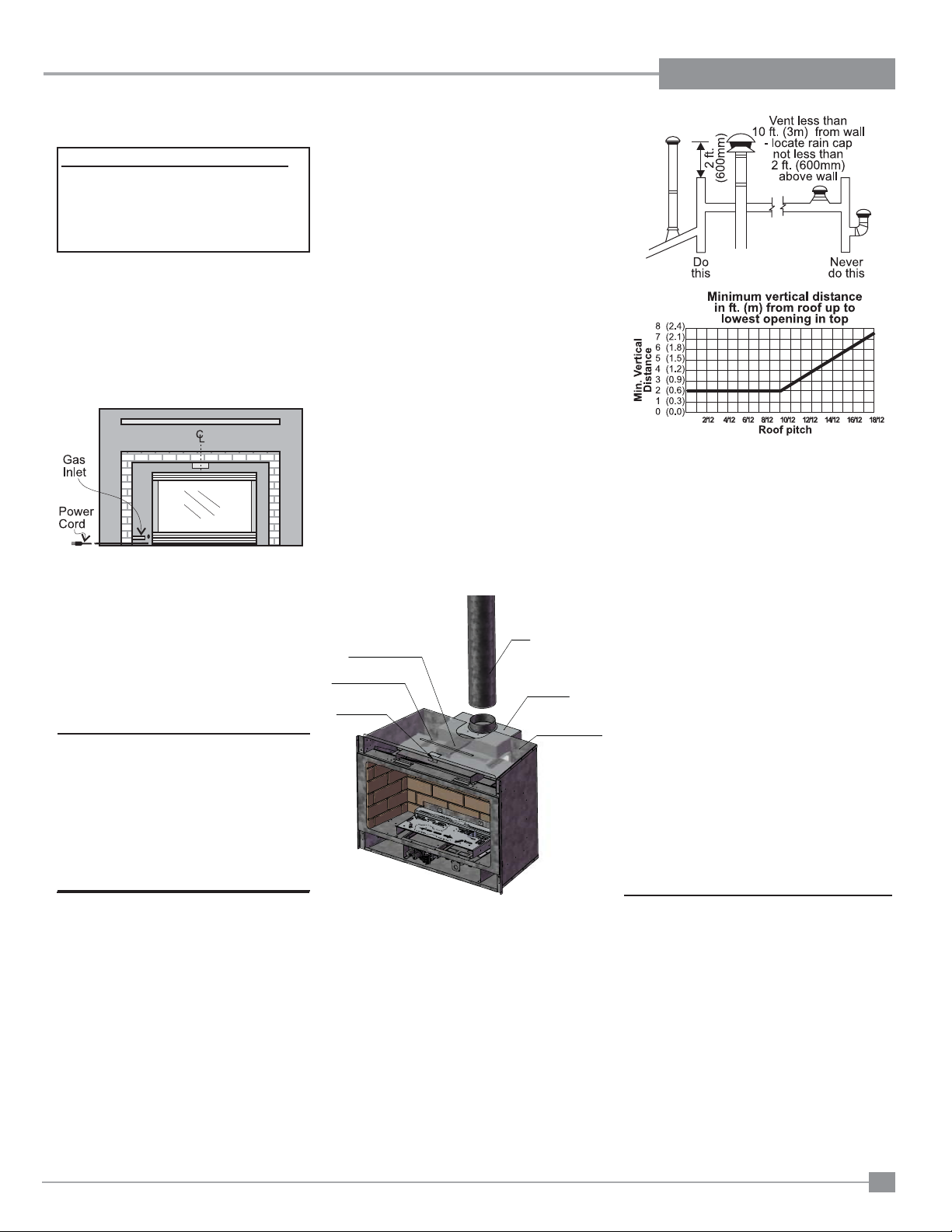
MATERIALS REQUIRED
No electrical power supply is required for the gas
control to operate. A 120 Volt AC power cord is
hooked up to the fan. Plug the 3 wire cord into
a suitable receptacle. Do not cut the ground
terminal off under any circumstances. When
connected with 120 volts, the appliance must be
electrically grounded in accordance with local codes,
or in the absence of local codes, with the current
Canadian Electrical Code CSA C22.1 (in Canada)
or with the current National Electrical Code ANSI/
NFPA 70-1987 (in U.S.A.).
NOTE: This unit is equipped with a heat sensor
thermodisc which will prevent the blower
from operating until the unit reaches the
correct temperature.
Note: If you are installing the Excalibur Surround,
the minimum fi replace dimensions are as follows:
Width (at front): 29" (737mm)
Depth: 16" (406mm)
Combustible Mantel Clearances in
Masonry Installation
Note: A non-combustible mantel may be in-
stalled at a
lower height
if the framing
is made of
metal studs
covered
with a noncombustible
board.
NOTE: Mantel clearances for Installation into
a Zero Clearance Kit are different. Please
refer to the Zero Clearance Kit Manual for
details.
Regency U31-3 Gas Fireplace Insert
9
Page 10
INSTALLATION
Conversion Kit from Natural Gas to Propane
Model #404-969 for: U31-NG3 Units
THIS CONVERSION MUST BE DONE BY A QUALIFIED GAS
FITTER IF IN DOUBT DO NOT DO THIS CONVERSION !!
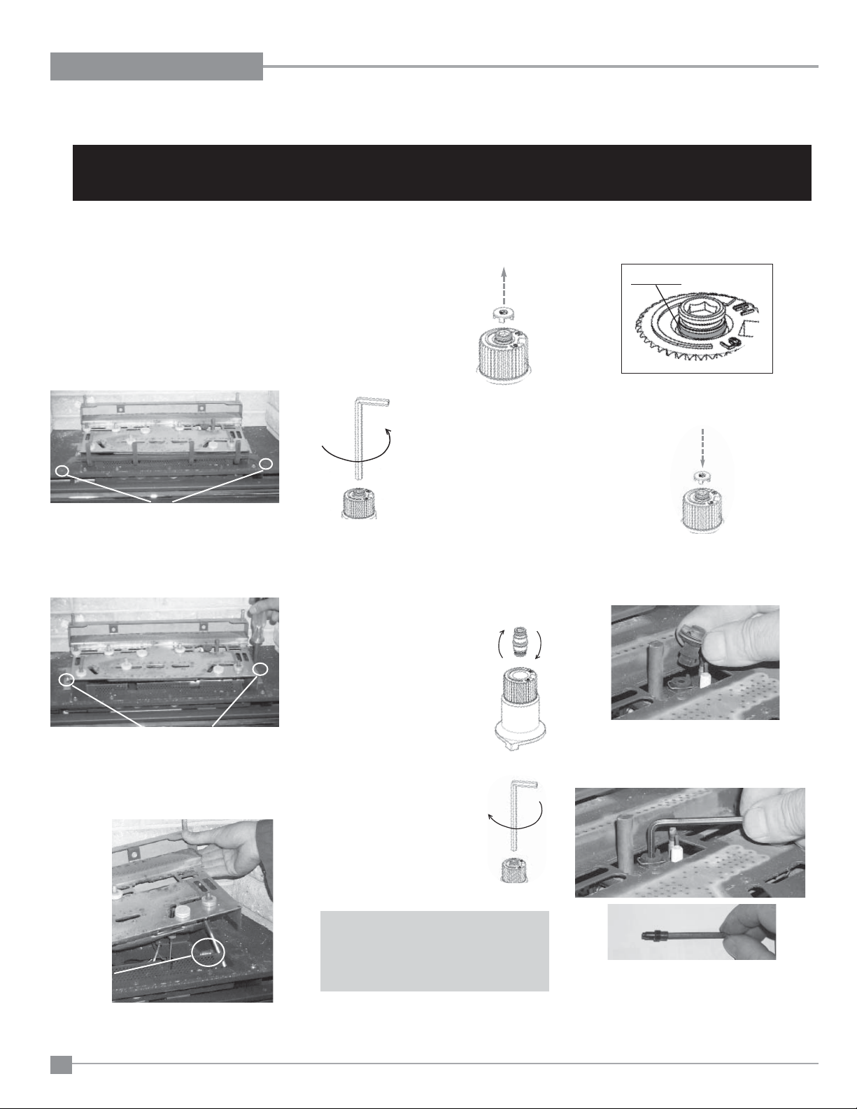
1) Turn the unit off and allow it to cool to room
temperature.
2) Unplug or disconnect power source to stove.
3) Remove glass front (see manual).
4) Remove logs and brick panels (if installed).
5) Remove the Grate by removing the screws
on each side of the grate.
Remove the 2 screws holding
the grate in position.
6) Remove the Burner Tray by removing the
screws on each side of the tray. Push the
tray to the left and lift up.
8) Turn control knob to the “OFF” position
9) Remove the black
protection cap by hand
from the hi-low knob (Fig.1).
Fig. 1
10) Insert a 5/32” or 4mm Allen
wrench into the hexagonal
key-way of the screw (Fig. 2),
rotate it counter-clockwise
until it is free and extract it.
Fig.2
11) Check that the screw is clean and if necessary
remove dirt.
14) Verify that if the conversion is from NG to LPG,
the screw must be re-assembled with the red
o-ring visible (Fig. 5).
Red o-ring visible
Fig.5
15) Re-assemble the black protection cap
(Fig. 6).
16) Reverse steps 6 - 1.
17) Pull off the pilot cap to expose the pilot orifi ce.
LPG Configuration
Remove the 2 screws,
push Burner Tray to the left, and lift off.
7) Remove burner orifi ce with 1/2" wrench and
replace with the #52 orifi ce in the Kit.
Burner
Orifi ce
12) Flip the screw (Fig. 3).
Fig.3
13) Using the Allen wrench as
shown in Fig.4, rotate the
screw clockwise until snug,
do not overtighten.
Fig.4
WARNING!
Do not over tighten the screw.
Recommended to
grip the wrench by the short side.
18) Unscrew the pilot orifi ce with the allen key and
replace with the LP pilot orifi ce in the kit.
19) Replace Burner Tray and reverse steps 5) to
1).
20) Adjust the burner aeration setting to 3/8" to
3/8" as required for the best fl ame picture.
10
Regency U31-3 Gas Fireplace Insert
Page 11
INSTALLATION
GAS CONNECTION
GAS CONNECTION WARNING:
Only persons licensed to work
with gas piping may make the
necessary gas connections to this
appliance.
1) If the appliance is to be installed into an
existing chimney system, thoroughly clean
the masonry or factory built fi replace.
2) The appliance is provided with an opening
on the left hand side of the control compartment. A 1/2" gas supply pipe must be
brought near this inlet hole. (See Diagram
3 on page 11).
3) Locate the center point where the vent will
pass through the chimney above the appliance. Move the appliance into the exact
location where it is to be installed. Ensure
that the Insert is level.
4) The installer must provide a valve with a
plugged tapping, accessible for test gauge
connection, immediately upstream of the
gas supply connection to the appliance.
HIGH ELEVATION
This unit is approved in Canada for altitude 0 to
2000 ft. with the orifi ce supplied. For 0' - 4500'
use the optional fi eld conversion kit (Part #400-
970 for Natural Gas units and Part #400-971 for
Propane units). In USA refer to ANSI Z223.11988, Appendix F, for re-sizing orifi ce.
Periodically check that the vent is unrestricted and
an adequate draft is present when the unit is in
operation. (See page 8 for spillage test.)
Before installing vent system ensure that the damper
plate is open and secure to prevent the damper plate
from falling down and crushing the liner.
DRAFT HOOD
CONNECTION
1) Attach the vent to the fl ue collar on the detach-
able draft hood. The fl ue collar of the appliance
will fi t inside a standard vent and may be fas-
tened directly to the vent by sheet metal screw.
Diagram 1.
2) Before pushing the appliance into position
inside the fi replace, align the draft hood with
the guides on the insert top and pull forward.
While pushing the unit back into place, keep
pulling the draft hood forward until the screw
hole in the spill tube aligns with the screw hole
in the draft hood locking tab on the underside
of fi rebox top. The screw is secured through the
draft hood locking tab into the front of the spill
tube. (If screw holes do not line up then draft
hood is not positioned correctly.
)OXH
'UDIW&KHFN7XEH
'UDIWKRRG*XLGHV
'UDIWKRRG
/RFNLQJ7DE
'UDIWKRRG
2XWHU6KHOO7RS
6KRZQ3DUWO\
7UDQVSDUHQW
WARNING: Operation of this appliance when not connected to a properly installed and maintained venting
system or tampering with the blocked
vent shutoff system can result in
carbon monoxide (CO) poisoning and
possible death.
Combustion and Ventilation Air
WARNING: This appliance needs
fresh air for safe operation and must
be installed with provisions for adequate combustion and ventilation
air available to the room in which it
is to be operating.
Follow CAN/CGA B149 (in Canada) or ANSI Z223.1
(in the USA) requirements, and any local codes or
regulations of the enforcing authority.
Air for combustion is drawn in through the front
of the unit, therefore, the front of the unit must be
kept clear of any obstructions.
VENTING
This appliance is designed to attach to a 4" diameter type B-Vent or listed gas fuel type vent liner
running the full length of the chimney. A minimum
fl ue height of 12 feet is recommended. B-Vent
must be supported by a vent support - supplied
by vent manufacturer. See chart on this page
for minimum distances from roof.
The Regency Insert incorporates its own internal
draft hood, so no additional external draft hood
is required.
Regency U31-3 Gas Fireplace Insert
Diagram 1
NOTE: fi nal gas connection should be after
unit is in place to avoid damage to line
when pushing the unit into position.
GAS PRESSURE TEST
The unit is preset to give the correct gas input at the
specifi ed manifold pressures shown on the label.
The maximum gas manifold pressure is:
Natural Gas 3.5" w.c.
Propane 10" w.c.
The manifold pressure is controlled by a regulator
built into the gas control, and should be checked at
the pressure test point. The pressure check should
be carried out with the unit burning and
11
Page 12

INSTALLATION
the setting should be within the limits specifi ed.
GAS INSERT AERATION
SYSTEM
The aeration adjustment rod is attached to the
air shutter which is located just above the orifi ce
bracket. The rod is used to adjust the aeration
on the main burner without having to take the
appliance apart.
The burner aeration is factory set but may need
adjusting due to either the local gas supply, air
supply or altitude.
Natural Gas: 3/8" (9.5mm) open
Propane: 3/8" (9.5mm) open
Note: Any damage due to carboning result-
ing from improperly setting the aeration controls is NOT covered under
warranty.
Note: Aeration Adjustment should only
be performed by an authorized FPI
Installer at the time of installation or
service.
Check for proper draft by placing a
match close to the draft check opening. This should be checked after the unit
Diagram 1
The smoke should be drawn into the spill tube. If
the smoke is still not drawn into the spill tube, turn
the unit off and check for the cause of the lack of
draft. If necessary, seek expert advice.
OPTIONAL
BRICK PANEL
1) Unwrap the brick pattern panels from the pro-
tective wrapping.
2) Remove the glass front if it is already installed.
3) Put the rear brick panel fl at against the back of
the unit.
Diagram 1
Back Panel
TEST FOR FLUE
SPILLAGE
A " spillage" test must be made before the
installed unit is left with the customer. Follow
the procedure below:
1) Start all exhaust fans in the home and then
close all external doors and windows in the
house.
2) Light the unit and set controls to maximum.
Turn fan off.
3) After fi ve minutes, test that there is a “pull” on
the fl ue by placing a smoke match, cigarette or
similar device which gives off smoke, in front
of the spill tube. T o ensure a valid test, place a
scrap piece of sheet metal (or other noncombustible material) between the spill tube and
the upper louver, this will prevent the natural
convection of the unit from interfering with the
test. See diagram 1.
For wind turbulent sites, a wind cap may remedy
the problem.
Note: The thermally activated safety switch will
sense the change in temperature and shut down
the gas valve in the event of a severe downdraft
or a blocked or disconnected vent. The switch
acts as a safety shut-off to prevent a build-up
of carbon monoxide. If the fl ue is blocked or
has no "draw", the switch will automatically
shut off the supply of gas within 5 - 10 minutes.
Tampering with the switch can result in carbon
monoxide (CO) poisoning and possible death.
If the heater turns off because of lack of draft
during the spillage test, check for the cause
and if necessary, seek expert advice.
4) Before installing the side brick panels, loosen
the screws for the brick tabs enough so that you
can slide the brick clips on to the screws easily
but that the tabs are secure. For the location
of the side brick tab screws see Diagram 2.
Diagram 2
5) Slide brick panel under brick clips, tighten screws
securing clips to complete installation.
Brick clip
12
The thermally actuated safety switch will automatically reset after it has cooled off. The switch
will continue to cycle until the draft problem is
corrected. DO NOT BYPASS OR DISCONNECT
THIS SWITCH.
Diagram 3
Regency U31-3 Gas Fireplace Insert
Page 13

INSTALLATION
LOG SET INSTALLATION
Read the instructions below carefully and refer to the diagrams. If logs are broken do not use the unit until
they are replaced. Broken logs can interfere with the pilot operation.
The gas log kit contains the following:
a) 02-43 Rear Log
b) 02-45 Front Right Log
c) 02-56 Middle Left Log
d) 02-46 Left Top Log
e) 02-47 Center Log
f) 02-48 Middle Right Log
g) 02-44 Front Left Log
h) 902-154 Embers
i) 902-153 Rockwool
j) 902-179/P Vermiculite
k) 946-669 Platinum Embers
(supplied with packaged manual)
Vermiculite
and embers
Vermiculite
and embers
Vermiculite
and embers
3) Place Rear Log A)02-43 on the two pins on the rear
log support.
The "02" refer numbers (i.e. 02-43) are
molded into the rear of each log.
Note: Install Optional Brick Panels prior to installing logs.
1) Carefully remove the logs from the box and unwrap
them. The logs are fragile, handle with care - do not
force into position.
2) Sprinkle the vermiculite around the fi rebox base. Take
some of the embers (approx. 1/3 of the bag) and
sprinkle over the vermiculite.
A)02-43
Pins on Rear Log Support
4) Place Front Right Log B)02-45 on the two pins as
shown.
B)02-45
Regency U31-3 Gas Fireplace Insert
13
Page 14

INSTALLATION
5) Place the Middle Left Log C)02-56 on the two pins as
shown.
C)02-56
7) Place the notch in Center Log E)02-47 over Log B)02-
45 and across the cutout on Log A)02-43.
E)02-47
Notch
A)02-43
B)02-45
Cutout
Logs A)02-43, C)02-56, and B)02-45 in position
6) Place the Left Top Log D)02-46 on the pin on Log
C)02-56 and on top of the cutout on Log A)02-43.
D)02-46
A)02-43
C)02-56
Pin
Cutout
Logs D)02-46 and E)02-47 in position.
8) Position notch in Front Right Log F)02-48 on Log
E)02-47 and push the bottom right edge against the
bracket on the burner tray and the front edge of the
rear burner.
Notch
F)02-48
Bracket
E)02-47
B)02-45
14
Regency U31-3 Gas Fireplace Insert
Page 15

INSTALLATION
Front edge of
rear burner
A)02-43
F)02-48
B)02-45
Side View
Bracket
The bottom right edge of Log F)02-48 must sit snugly against
the bracket and the front edge of the rear burner.
9) Place Front Left Log G)02-44 onto the 2 front pins as
shown.
10) Place the embers and Rockwool on the exposed front
burner tray.
11) Separate platinum embers and place on and around
the embers and rockwool on the burner tray. Avoid
stacking platinum embers.
12) Test fi re to ensure proper light off (make sure fl ame
fl ows smoothly from one end of burner to the other. If
there is any fl ame hesitation, check that area for any
blockage of the burner port.
G)02-44
A) 02-43 D) 02-46
C) 02-44
B) 02-56
The "02" refer numbers (i.e. 02-43) are
molded into the rear of each log.
G) 02-48
F) 02-47 E) 02-45
Regency U31-3 Gas Fireplace Insert
15
Page 16

INSTALLATION
FACEPLATE & TRIM
INSTALLATION
1) Lay the faceplate panels fl at, face down on
something soft so they don't scratch.
2) Take the top faceplate and align the holes in
it with the holes in the side panels. Using the
screws provided, attach from the top of the
panel (the holes in the top panel are slightly
larger than the holes in the side panel to
facilitate easier installation). Diagram 1.
Hint: Don't tighten the screws down com-
Rear View: Faceplate Assembly
Diagram 1
pletely at this point, continue on with steps
3 and 4 and do a trial fi t to the unit. Make
any necessary adjustments and when it fi ts
properly then tighten down the screws.
Hearth Trim Option: Hearth Trim is an
option that can be used to fi nish off the
installation when the bottom of the fi replace
is higher than the hearth or to raise the fi re-
place. Attach the Hearth T rim to the bottom
of the faceplate side panels with the screws
provided. See Diagram 1.
Rear View: Trim Assembly
Diagram 2
the grey harness) and connect them with
the wire connectors from the fan speed
control.
6) Connect the ON/OFF switch wires by taking
the black and red wires with the female ends
and connect them to the ON/OFF switch.
7) Tuck the wires into the faceplate to keep
them away from the insert using the clip
provided. Attach the clip to the rear of the
faceplate to ensure that the wires do not
touch the side of the unit. Diagram 3.
8) The power cord should be run behind the
faceplate panel.
Diagram 3
Diagram 4
Diagram 5
3) Using the connectors provided, join the left
side trim (with the ON/OFF switch) to the
top trim. Diagram 2. Connect the right side
trim to the top trim.
4) Place the trim on the assembled faceplate
panels, aligning the wire connections from
the switches with the notch on the left side
panel.
5) Connect the fan switch wires by taking the
black and red wires with the male ends (in
16
9) Attach the brass trim to the faceplate by
drilling a 1/8" hole through into the faceplate
using the hole in the trim as a guide. Fasten
the trim to the faceplate panels using the
plated screws. Diagram 4.
10) Attach the faceplate panels to the insert
body using the 4 remaining black screws.
Diagram 5.
11) Push the Regency logo plate into the two
holes in the bottom left corner of the faceplate.
Regency U31-3 Gas Fireplace Insert
Page 17

INSTALLATION
FLUSH FRONT
INSTALLATION
1) Install Logs before going on to the next step. See
the Log Installation instruction sheet or page 9.
2) Install the bottom glass trim by hooking the trim
into the lip on the fi rebox base. The trim will not
fi t into place if the glass is installed fi rst.
3) Place the bottom of the fl ush glass behind the
bottom glass trim.
MESH GUARD INSTALL
Line up hooks on mesh guard with slots on unit.
Slide mesh guard down into slots until securely
in place.
Mesh Guard
FLUSH LOUVERS
1) The Top Louver is held in place by friction
fi t, if the Louver needs to be adjusted; bend
the bracket out as shown in the diagram.
2) Install the Spring Hinges on the left and right
side of the bottom of the Firebox using 2
screws per hinge.
4) Secure the glass with the two glass clips at the
top corners of the glass. Secure glass clips with
the screws provided. Do not over tighten as this
could break the glass.
5) Slide in the top glass trim under the spring clips.
3) Place the Bottom Louver near the hinge. Flip
hinge over the Bottom Louver and secure
using 3 screws.
Hinge
Location
Bottom Louver
Regency U31-3 Gas Fireplace Insert
17
Page 18

INSTALLATION
WIRING DIAGRAM
This heater does not require a 120V A.C. supply for operation. In case of a power failure, the burner switch and the optional remote control/thermostat will
continue to operate. However, a 120V A.C. power supply is needed for the fan/blower operation.
Caution: Ensure that the wires do
not touch any hot surfaces and are
away from sharp edges.
Grounding
Lug Detail
Lockwasher
Star washer
Star washer
Gas
In
nut
nut
O
F
F
P
I
L
O
T
N
O
Ground wire
from fan
Ground wire
from power cord
Pilot
Assembly
O
L
H
I
White
Brown
Thermopile
Gas Pilot
Electrode
To
Pilot
Gas
Red
Thermocouple
ValveTo
Piezo
Ignitor
120V AC
Neutral
Live
Ground
Minimum Convection
Air Temp. Switch
CAUTION: Label all wires prior
to disconnection when servicing controls. Wiring errors can
cause improper and dangerous
operation.
Fan
Green
ON OFF
Red Black Black
Rotary Speed
Control
Black
Red
ON
OFF
Burner
Ground
Black
"S.I.T" Valve
Vent Spill
Switch
(Auto Reset)
ONOFF
Remote
Receiver
(Optional)
(Millivolt)
Thermostat
(Millivolt)
(Optional)
Remote Transmitter
(Optional)
Regency
WARNING: Electrical Grounding Instructions
This appliance is equipped with a three pronged (grounding) plug for your protection against shock hazard and should
be plugged directly into a properly grounded three-prong receptacle. Do not cut or remove the grounding prong from
this plug.
18
Regency U31-3 Gas Fireplace Insert
Page 19

FULL SCREEN FRONT
INSTALLATION
1) Hold the full screen door up against the unit in order to make the
following wire connections.
Pull the ON/OFF connector wires from the fi rebox and connect them
to the switch.
Connect the fan switch wires with the wire connectors from the fan
speed control. Place clips over wires and tuck into side trim.
3) Completely secure the full screen door to the unit by securing 4
screws to the Left and Right Side Trims.
.
NOTE: When mounting the full screen door to the unit, the inside
fl ange of the side trims are to fi t over the inner side of the unit fl ange
and NOT next to the outer side of the unit fl ange.
2) Lift unit up slightly and push down on the corners of the Bottom Trim
Bracket and slide under unit. Unit should touch tabs on Bottom Trim
Bracket.
Push in Corners
Bottom Trim Bracket
Inside fl ange of Side Trim goes over
the inner side of the unit fl ange.
Regency U31-3 Gas Fireplace Insert
19
Page 20

INSTALLATION
EXCALIBUR SURROUND
INSTALLATION
IMPORTANT NOTE:
When using the Surround, the unit must be set 1" further into the fi replace
than the standard faceplate installation. See the diagrams below for the
correct minimum fi replace opening requirements.
16”
C
L
29”
f
21”
2) Align the cut-outs in the Blanking Plate with the pins located on the
inside top of the fi rebox. Slide the Blanking Plate into position ensuring
it goes under the 2 fl anges.
Flanges
Blanking Plate
3) Hold the Faceplate Trim up against the unit in order to make the
following wire connections.
1) Align the left side Faceplate Trim Bracket with the Firebox Flange
and secure using 2 screws as shown in diagram 1. Repeat for right
side.
Faceplate Trim
Bracket
Firebox
Flange
Pull the ON/OFF connector wires from the fi rebox and connect
them to the switch.
Connect the fan switch wires with the wire connectors from the fan
speed control. Place clips over wires and tuck into side trim.
ON/OFF
switch
Fan Speed
wires to
ON/OFF
switch
Switch
(Rear View)
wires to
Fan switch
for gas
connectors
connection
Self-adhesive
wire clip
20
Regency U31-3 Gas Fireplace Insert
Page 21

INSTALLATION
4) Secure the Faceplate by sliding the slots in the Faceplate into the
fl anges on the left and right side Faceplate Trim Brackets. Once
the Faceplate is in place secure using 2 screws per side.
Faceplate
5) Place the bottom hooks of the Surround into the bottom slots of the
Faceplate. Slightly pull up the Surround and push the top hooks into
the top slots of the Faceplate. Push down to secure. Tug on the Surround to ensure it is securely locked in place.
Backside of Sur-
round Shown
Hooks
Left Side
Faceplate Bracket
Trim Flange
Faceplate
Slots
Faceplate
Surround
Regency U31-3 Gas Fireplace Insert
21
Page 22

INSTALLATION
LOW PROFILE FACEPLATE INSTALLATION
1) Attach the inner faceplate panel to the insert body using 4 screws
in the locations shown below.
Diagram 1
Diagram 2
Connect the male end black and red fan switch wires to the wire
2)
connectors from the fan speed control.
4) Tuck the wires into the clip to keep them away from the insert using
the clip provided. Attach the clip to the rear of the faceplate to ensure that the wires do not touch the side of the unit. The power cord
should be run behind the inner faceplate panel.
Diagram 5
5) Install the on /off switch - fan speed control box to the left hand
bottom leg of the inner faceplate. Controls located on the left side.
Diagram 3
Connect the female ends of the ON/OFF switch - to the ON/OFF
3)
switch in the control box.
Diagram 4
22
Diagram 6
6) Feed wires through the left air chamber clip - then clip them it to
lower left of fi rebox as show below.
Wire
Diagram 7
Regency U31-3 Gas Fireplace Insert
feed
Page 23

INSTALLATION
e
g
7) Clip the right side air chamber clip as shown below in Diagram 8.
Diagram 8
8) Attach 2 brackets near the bottom of the unit with one screw as
shown below in Diagram 9 (left and right brackets are interchangeable.
10) Hook door frame on 2 pins over glass door in locations shown
below in Diagram 11.
Diagram 11
11) Take the outer faceplate, line up the openings on the left and right
legs and install onto the inner faceplate panel pins.
Diagram 9
9) Attach Regency logo to bottom louver. Install bottom louver by
hanging louver on brackets installed in step 8.
Diagram 10
Attach Regency logo to left
side of bottom louver
Bracket
Inner faceplate
panel pins
Final Install
Diagram 12
Dia
ram 13
Outer fac
Regency U31-3 Gas Fireplace Insert
23
Page 24

OPERATING INSTRUCTIONS
OPTIONAL WALL
THERMOSTAT
A wall thermostat may be installed if desired. Connect the wires as per the wiring diagrams. Note
that the wires are connected to the "TH" on the
gas valve. Use table on page 14 to determine the
maximum wire length:
Note: Preferable if the thermostat is installed
on an interior wall.
FPI offers an optional programmable thermostat
but any 250-750 millivolt rated non-anticipator
type thermostat that is CSA, ULC or UL approved
may be used.
CAUTION
Do not connect the millivolt
wall thermostat wires
to the 120V wires.
Thermostat Wire Table
Recommended Maximum Lead Length
(Two-Wire) When Using Wall
Thermostat (CP-2 System)
3) Install 3 AAA alkaline batteries in transmitter and
4 AA alkaline batteries in the receiver. Install
the receiver and its cover in the wall. Switch the
remote receiver to "remote" mode. The remote
control is now ready for operation.
FINAL CHECK
Before leaving this unit with the customer, the
installer must ensure that the appliance is fi ring
correctly. This includes:
1) Clocking the appliance to ensure the correct
fi ring rate (rate noted on label) at 15 minutes.
2) If required, adjusting the primary air to ensure
that the fl ame does not carbon. First allow the
unit to burn for 15 min. to stabilize.
CAUTION
Any alteration to the product that causes sooting or carboning that results in damage to the
exterior facia is not the responsibility of the
manufacturer.
OPERATING
INSTRUCTIONS
2) If the control knob is in the "OFF" position
proceed to Step 5.
3) Push in gas control knob slightly and turn
clockwise to "OFF". Knob cannot be turned
from "PILOT" to "OFF" unless knob is pushed
in slightly. Do not force.
4) Wait fi ve minutes to allow gas, that may have
accumulated in the main burner compartment,
to escape. If you do smell gas, follow the instructions on the front of this manual. If you don't
smell gas continue on to the next step.
5) Turn the gas control counter clockwise to "PILOT".
6) Push in control knob all the way and hold in.
Continually push and release the black button
on spark igniter until pilot lights. Continue to
hold the control knob in for approximately one
minute, then release the gas control knob. The
pilot fl ame should continue to burn. If the pilot
does not remain lit, repeat operation allowing
a longer period before releasing gas control
knob.
7) Turn gas control knob counter clockwise to
"ON".
Wire Size
14 GA. 50 Ft.
16 GA. 32 Ft.
18 GA. 20 Ft.
20 GA. 12 Ft.
22 GA. 9 Ft.
Max. Length
OPTIONAL REMOTE
CONTROL
Use the FPI Remote Control Kit approved for
this unit. Use of other systems may void your
warranty.
The remote control kit comes with a hand held
transmitter, a receiver and a wall mounting plate.
1) Choose a convenient location on the wall
to install the receiver and the receptacle
box (protection from extreme heat is very
important). Run wires from the fi replace to
that location, use Thermostat Wire Table.
2) Connect the wires as per the wiring diagram
above.
CAUTION
Do not connect the millivolt
remote control wires to
the 120V wires.
Before operating this appliance, proceed through
the following check list.
1) Read and understand these Instructions before
operating this appliance.
2) Check to see that all wiring is correct and
enclosed to prevent possible shock.
3) Check to ensure there are no gas leaks.
4) Make sure the glass door is in place. Never
operate the appliance with the door glass
removed.
5) Verify that all venting and the cap is unobstructed.
6) Verify log placement. If the pilot cannot be seen
when lighting the unit - the logs or the embers
have been incorrectly positioned.
7) The unit should never be turned off and on
again without a minimum of a 60 second wait.
8) When lighting the appliance, the inside of the
glass may fog up. This will burn off after a few
minutes of operation.
LIGHTING
PROCEDURE
IMPORTANT: Gas cock knob cannot be turned
from "PILOT" to "OFF" unless it is partially
depressed.
8) Use the rocker switch to operate main burner.
9) Rotate the variable fl ame control to adjust the
fl ame height higher or lower.
10) Close the bottom louver assembly.
820 S.I.T. VALVE
DESCRIPTION
1) Gas on/off knob
2) Manual high/low adjustment
3) Pilot Adjustment
4) Thermocouple Connection - option
5) Outlet Pressure Tap
6) Inlet Pressure Tap
7) Pilot Outlet
8) Main Gas Outlet
9) Alternative TC Connection Point
24
24
1) Open the bottom louver assembly
Regency U31-3 Gas Fireplace Insert
Page 25

OPERATING INSTRUCTIONS
INSTALLATION
SHUTDOWN
PROCEDURE
1) Use the rocker switch to turn off the
main burner.
2) Open the bottom louver assembly.
3) Push in the gas control knob slightly
and turn clockwise to "OFF". Do not
force.
4) Disconnect all electric power and
gas to the appliance if service is to
be performed.
FIRST FIRE
The fi rst fi re in your stove is part of the
paint curing process. To ensure that the
paint is properly cured, it is recommended
that you burn your fi replace for at least
four (4) hours the fi rst time you use it
with the fan on. When fi rst operated,
the unit will release an odour caused by
the curing of the paint, the burning off of
any oils remaining from manufacturing.
Smoke detectors in the house may go
off at this time. Open a few windows to
ventilate the room for a couple of hours.
COPY OF LIGHTING INSTRUCTION PLATE
OFF
The glass panel may require cleaning
after the unit has cooled down.
DO NOT ATTEMPT TO CLEAN THE
GLASS WHILE IT IS HOT.
Note: When the glass is cold and
the appliance is lit, it may
cause condensation and fog
the glass. This condensation
is normal and will disappear
in a few minutes as the glass
heats up.
DO NOT BURN THE APPLIANCE WITHOUT THE GLASS
FRONT IN PLACE.
AUTOMATIC
CONVECTION
FAN OPERATION
The fan operates automatically, turn the knob
on the side of the faceplate to adjust to the
desired speed. The fan will turn on as the stove
comes up to operating temperature. After the
unit has been turned off and the unit cooled to
below a useful heat output range the fan will
shut off automatically.
NORMAL OPERATING SOUNDS OF
GAS APPLIANCES
It is possible that you will hear some sounds
from your gas appliance. This is perfectly
normal due to the fact that there are various
gauges and types of steel used within your
appliance. Listed below are some examples.
All are normal operating sounds and should
not be considered as defects in your appliance.
Blower:
FPI gas appliances use high tech blowers to
push heated air farther into the room. It is not
unusual for the fan to make a "whirring" sound
a
when ON. This sound will increase or decrease
in volume depending on the speed setting of
your fan speed control.
Burner Tray:
The burner tray is positioned directly under the
burner tube(s) and logs and is made of a different gauge material from the rest of the fi rebox
and body. Therefore, the varying thicknesses of
steel will expand and contract at slightly different
rates which can cause "ticking" and "cracking"
sounds. Y ou should also be aware that as there
Regency U31-3 Gas Fireplace Insert
2525
Page 26

MAINTENANCE
are temperature changes within the unit these
sounds will likely re-occur. Again, this is normal
for steel fi reboxes.
Blower Thermodisc:
When this thermally activated switch turns ON
it will create a small "clicking" sound. This is the
switch contacts closing and is normal.
Pilot Flame:
While the pilot fl ame is on it can make a very
slight "whisper" sound.
Gas Control Valve:
As the gas control valve turns ON and OFF, a
dull clicking sound may be audible, this is normal
operation of a gas regulator or valve.
Unit Body/Firebox:
Different types and thicknesses of steel will
expand and contract at different rates resulting
in some "cracking" and "ticking" sounds will be
heard throughout the cycling process.
MAINTENANCE
INSTRUCTIONS
1) Always turn the gas valve to off before
cleaning. For relighting, refer to lighting
instructions. Keep the burner and control
compartment clean by brushing and vacuuming at least once a year.
When cleaning the logs, use a clean soft
paint brush as the logs are fragile and easily
damaged.
2) Clean (never when unit is hot) appliance,
door and louvers with a damp cloth. Never
use an abrasive cleaner. The gold louvers
(and optional gold door) may be scratched
if abrasives are used to clean them.
The heater is fi nished in a heat resistant
paint and should only be refi nished with
heat resistant paint (not with wall paint).
FPI uses StoveBrite Paint - Metallic Black
#6309.
3) Make a periodic check of burner for proper
position and condition. Visually check the
fl ame of the burner periodically, making sure
the fl ames are steady; not lifting or fl oating.
If there is a problem, call a qualifi ed service
person.
4) The appliance and venting system must be
inspected before use, and at least annually,
by a qualifi ed fi eld service person, to ensure
that the fl ow of combustion and ventilation
air is not obstructed.
During the annual service call, the burners
should be removed from the burner tray
and cleaned. Replace the embers but do
not block the pilot.
5) Keep the area near the appliance clear and
free from combustible materials, gasoline
and other fl ammable vapours and liquids.
WARNING: CHILDREN AND
ADULTS SHOULD BE ALERTED
TO THE HAZARDS OF HIGH
SURFACE TEMPERATURE AND
SHOULD STAY AWAY TO AVOID
BURNS OR CLOTHING IGNITION.
YOUNG CHILDREN SHOULD BE
CAREFULL Y SUPERVISED WHEN
THEY ARE IN THE SAME ROOM
AS THE APPLIANCE.
CAUTION: ANY SAFETY SCREEN
OR GUARD REMOVED FOR SERVICING AN APPLIANCE MUST BE
REPLACED PRIOR TO OPERATING THE APPLIANCE.
CLOTHING OR OTHER FLAMMABLE MA TERIAL SHOULD NOT
BE PLACED ON OR NEAR THE
APPLIANCE.
6) Each time the appliance is lit, it may cause
condensation and fog the glass. This
condensation and fog is normal and will
disappear in a few minutes as the glass
heats up.
Never operate the appliance without the
glass properly secured in place, with
broken glass or with the door open.
7) Verify proper operation after servicing.
8) Periodically check the pilot fl ames, there
should be three strong blue fl ames approx.
3/4" long - 1 fl ame to the front burner, and
1 to the thermopile and one to the left. See
diagrams below.
Correct fl ame pattern has four strong blue
fl ames: 1 fl owing around the thermopile and
thermocouple and 1 reaching towards the
rear burner and 1 toward the front(it does
not have to be touching the burner).
Top View of pilot fl ame
Incorrect fl ame pattern will have small, prob-
ably yellow fl ames, not coming into proper
contact with the rear burner or thermopile.
Top View of pilot fl ame
If you have an incorrect fl ame pattern,
contact your FPI dealer for further instructions.
GOLD-PLATED TRIM
The 24 carat gold plated fi nish on the trim
requires little maintenance, and need only be
cleaned with a damp cloth. DO NOT use abrasive
materials or chemical cleaners, as they may
harm the fi nish and void the warranty.
Clean any fi ngerprints off before turning the
unit on. If the top louvers start to discolour,
check the door gasket seal and replace if
necessary.
LOG REPLACEMENT
The unit should never be used with broken logs.
Turn off the gas valve and allow the unit to cool
before opening door to carefully remove the
logs. The pilot light generates enough heat to
burn someone. If for any reason a log should
need replacement, you must use the proper
replacement log. The position of these logs
must be as shown in the diagram under Log
Installation.
NOTE: Improper positioning of logs may
create carbon build-up and will alter
the unit’s performance which is not
covered under warranty.
GLASS GASKET
If the glass gasket requires replacement use
7/8" fl at glass gasket (Part # 936-243) for the
Bay Front and for the Flush Front.
26
Regency U31-3 Gas Fireplace Insert
Page 27

FAN MAINTENANCE
MAINTENANCE
DOOR GLASS
REPLACEMENT
Y our Regency insert is supplied with high temperature, 5 mm Neoceram ceramic glass that
will withstand the highest heat that your unit
will produce. In the event that you break your
glass by impact, purchase your replacement
from an authorized FPI dealer only, and follow
our step-by-step instructions for replacement.
WARNING: do not operate appliance with the glass front removed,
cracked or broken. Replacement
of the glass should be done by a
licensed or qualifi ed service per-
son.
Flush Glass Replacement
Slide old glass out of the side frames and replace
with new glass.
If your fan requires maintenance or replacement,
access to the fan is through the plate on the
rear wall of the fi rebox. NOTE: the unit MUST
NOT be operated without the fan access
panel securely in place.
CAUTION: Label all wires prior to
disconnection when servicing controls. Wiring error can cause improper
and dangerous operation.
To remove fan:
1) Turn the unit off and allow it to cool to room
temperature.
2) Unplug or disconnect power source to
stove.
3) Remove glass front (see page 11).
4) Remove logs.
5) Remove brick panels.
6) Remove the Grate by removing the screws
on each side of the grate.
)LUHER[VKRZ
DVWUDQVSDUHQW
)DQ'XFW
DQ&RYHU
3ODWH
)LUHER[5HDU
)DQ0RXQWLQJ
6WXGDQG*URPPHW
10) Unplug the black wires from the fan motor (from
inside the stove).
)DQ
Remove the 2 screws holding the
grate in position.
7) Remove the Burner Tray by removing the
screws on each side of the tray. Push the
tray to the left and lift up.
Remove the 2 screws,
push Burner Tray to the left, and lift off.
8) Remove the 12 screws holding the Access
Panel in place.
11) Lift Fan Assembly off of the 2 pins, tip forward
and pull through fi rebox opening.
12) Disconnect green wire from power cord.
Replacing fan:
Reverse above steps. Hint for pushing fan down
onto pins - rub a bit of dish soap on the grommet so
it will slide more easily onto the pin. Check to make
sure the fan is seated properly on the pins, this is
very important- try to move the fan back and forth,
there should be no noise, if there is check that the
grommets haven't come loose.
When replacing the Burner Tray, slide the aeration
adjustment rod through the opening in the front of
the Valve Assembly.
Aeration Adjustment Rod
Regency U31-3 Gas Fireplace Insert
9) Remove the Fan Air Duct by removing 4
screws, 2 per side.
27
Page 28

PARTS LIST
Main Assembly
Part # Description Part # Description
1) 400-011 Fan Opening Cover
2) 911-071/P Fan Motor (120 V)
5) 910-750 Power Cord (120 V)
910-752 Wire Harness (intermediate)
34) * Brick Panel - Left Side
35) * Brick Panel - Right Side
36) 400-090 Brick Clips
78) 410-920 Zero Clearance Ashlip
6) * Thermodisc cover
7) * Thermodisc bracket
8) 910-142 Thermodisc-Fan Auto ON/OFF
10) * Drafthood Assembly
11) * Spill Switch Bracket
12) 910-220 Spill Switch
13) * Levelling Bolts 5/16 x 3 Hex Head
16) * Cable Tie
17) * Wire Holder Clip
18) * Strain Relief
19) * Grommet for Power Cord
20) 400-024 Air Channel
21) 402-922 Flush Louvers (Set) - Gold/Black
402-920 Flush Louvers (Set) - Black
402-924 Flush Louvers (Set) - Steel/Black
33) 404-901 Brick Panel Set - Standard Brown
404-902 Brick Panel Set - Standard Red
* Brick Panel - Back
410-905 Zero Clearance Kit
404-969 Conversion to LP Kit
919-099 Manual
*Not available as a replacement part.
10
28
33
2
Regency U31-3 Gas Fireplace Insert
Page 29

Burner Assembly & Log Set
Part # Description
404-574/P Valve Assembly - NG
404-576/P Valve Assembly - LP
52) 910-568 SIT 820 Valve -NG/LP**
53) 910-190 Piezo Ignitor and nut
54) * Valve Heat Shield
56) * Pilot Bracket
57) 904-240 Burner Orifi ce Nat. Gas #37
904-593 Burner Orifi ce Nat. Gas #40 (High Altitude)
904-390 Burner Orifi ce LP # 52
904-345 Burner Orifi ce Nat. Gas #53 (High Altitude)
60) 402-526 Grate Assembly
62) 404-525 Burner Assembly NG/LP
63) 910-048 Pilot Assembly (NG) 4 fl ame convertible top
910-049 Pilot Assemby (LP) 4 fl ame convertible top
67) * Firebox Base
PARTS LIST
69) 402-935 Log Set
402-572 Ember Package
70) * Air Channel
72) * Glass Trim Retainer
73) * Firebox back and top
74) * Glass Gasket Retainer
75) * Firebox Baffl e
76) 400-090 Brick Clip
77) * Fan Access Plate
78) * Thermodisc Bracket
79) * Thermodisc cover plate
80) * Fan Shield
*Not available as a replacement part.
**Not Shown
70
72
73
74
75
76
77
Regency U31-3 Gas Fireplace Insert
78
67
79
80
29
Page 30

PARTS LIST
Flush Front Assembly
Part # Description
Flush Door
402-515/P Complete Flush Front
150) 936-243 Door Frame Gasket - 7/8"
153) * Glass Side Trim
154) * Flush Glass
155) 402-046 Glass Support Trim - Black
156) 936-238 Flush Glass Gasket
157) * Screw #10-24 x 1/2"
158) 402-033 Flush Glass Bracket
159) 936-233 3/4" Rope Gasket
*Not available as a replacement part.
30
Regency U31-3 Gas Fireplace Insert
Page 31

Faceplate Assembly
Part # Description
402-919 Complete Faceplate (Set) with Black Trim - Oversize
41) * Faceplate Side Right - Oversize
42) * Faceplate Top - Oversize
43) * Faceplate Side Left Assy-Oversize
402-534 Trims Pkg. - Oversize, Zero Clearance
44) * Faceplate Trim Right - Oversize
45) * Faceplate Trim Top - Oversize
46) * Faceplate Trim Left Assy - Oversize
400-917 Complete Custom Faceplate (Set)
71) * Faceplate Side Right - Custom
72) * Faceplate Top - Custom
73) * Faceplate Side Left - Custom
412-906 Complete Faceplate (Set) with Black Trim - Zero Clearance
81) * Faceplate Side Right - Zero Clearance
82) * Faceplate Top - Zero Clearance
83) * Faceplate Side Left Assy-Zero Clearance
402-534 Trims Pkg. - Zero Clearance
85) 836-203 Thermal Insulation - Top
400-939 Valve Access Faceplate
89) * Faceplate Side Left Assy
90) * Cover Plate - Valve Access
PARTS LIST
402-918 Complete Faceplate (Set) with Black Trim - Standard
91) * Faceplate Side Right - Standard
92) * Faceplate Top - Standard
93) * Faceplate Side Left Assy - Standard
402-532 Trims Pkg. - Standard
94) * Faceplate Trim Right - Standard
95) * Faceplate Trim Top - Standard
96) * Faceplate Trim Left Assy - Standard
402-933 Molded Faceplate Complete (Set)
141) * Faceplate Side Right - Molded
142) * Faceplate Top - Molded
143) * Faceplate Side Left Assy -Molded
144) 402-044 Mounting Bracket - Right
145) 402-045 Filler Bracket
146) 402-043 Mounting Bracket - Left
147) * Screw - #8 x 3/4" Pan Head
400-950 Hearth Trim 1" - Standard
320-940 Hearth Trim 1" - Oversize
400-926 Hearth Trim 2" - Standard
320-942 Hearth Trim 2" - Oversize
180) 400-928 Hearth Trim 4" - Standard
181) 320-944 Hearth Trim 4" - Oversize
400-959 Hearth Trim 6" - Standard
320-946 Hearth Trim 6" - Oversize
184) 410-525/01 Hearth Trim 4" - Zero Clearance
185) 904-569 Fan Speed Control Knob (120 V)
186) 904-586 Speed Control Knob c/w Spring Clip
187) 910-246 Burner ON/OFF Switch
188) 910-330 Fan Speed Control (120 V)
190) * Screw #8 x 1/2" Black self-tapping
191) * Screw #8 x 1/2" Brass self-tapping
199) 948-220 Hampton Logo Plate
*Not available as a replacement part.
Regency U31-3 Gas Fireplace Insert
31
Page 32

PARTS LIST
32
Regency U31-3 Gas Fireplace Insert
Page 33

LOW PROFILE FACEPLATE
Part # 403-954 Description
1) * Back plate Assembly
2) * Bottom Louver
3) * Right mounting bracket
4) * Left mounting bracket
5) * Front Frame
5
PARTS LIST
4
1
2
3
Regency U31-3 Gas Fireplace Insert
33
Page 34

NOTES
34
Regency U31-3 Gas Fireplace Insert
Page 35

WARRANTY
Regency® Fireplace Products are designed with reliability and simplicity in mind. In addition, our internal Quality Assurance Team carefully inspects each unit
thoroughly before it leaves our facility. FPI Fireplace Products International Ltd. is pleased to extend this limited lifetime warranty to the original purchaser of a
Regency® Product. This warranty is not transferable.
The Warranty: Limited Lifetime
The combustion chamber, heat exchanger, burner tubes/pans, logs, glass crystals, ceramic spa stones, pebbles, brick panels and gold plating (against defective manufacture
only) are covered under the Limited Lifetime Warranty for fi ve (5) years for parts and subsidized labour* and parts only thereafter.
Glass is covered for lifetime against thermal breakage only, parts and subsidized labour* for fi ve (5) years and parts only thereafter from date of purchase.
External casting, surrounds and grills are covered against cracks and warps resulting from manufacturer defects, parts and subsidized labour* for three (3) years from the date
of purchase and parts only thereafter.
Special Finishes - One year on stainless steel panels, nickel overlays,nickel faceplates, brushed nickel and antique copper full screens and doors. Y ou can expect some changes
in color as the product "ages" with constant heating and cooling. FPI warranties the product for any manufacturing defects on the original product. However, the manufacturers
warranty does not cover changing colors and marks, ie. fi nger prints, etc applied after the purchase of the product. Damage from the use of abrasive cleaners is not covered
by warranty.
Electrical and mechanical components such as blowers, switches, wiring, thermodiscs, FPI remote controls, spill switches, thermopiles, thermocouples, pilot assembly components,
and gas valves are covered for two years parts and one year subsidized labour* from the date of purchase. Blowers and valves replaced under warranty are considered repairs
and continue as if new with appliance. ie. twelve (12) months from original purchase date of appliance with a minimum of three (3) months coverage from date of replacement.
FPI venting components are covered parts and subsidized labour* for three (3) years from date of purchase.
Simpson Dura-Vent venting components (Direct Vent units) are covered by Simpson Dura-Vent Inc. warranty.
Repair/replacement parts purchased by the consumer from FPI after the original coverage has expired on the unit will carry a 90 day warranty, valid with a receipt only. Any
item shown to be defective will be repaired or replaced at our discretion. No labor coverage is included with these parts.
Conditions:
Any part or parts of this unit which in our judgement show evidence of such defects will be repaired or replaced at FPI's option, through an accredited distributor or agent provided
that the defective part be returned to the distributor or agent Transportation Prepaid, if requested.
Porcelain/Enamel - Absolute perfection is either guaranteed nor commercially possible. Any chips must be reported and inspected by an authorized dealer within three days of
installation. Reported damage after this time will be subject to rejection.
It is the general practice of FPI to charge for larger, higher priced replacement parts and issue credit once the replaced component has been returned to FPI and evaluated
for manufacturer defect.
The authorized selling dealer is responsible for all in-fi eld service work carried out on your Regency
unauthorized service persons or dealers.
At all times FPI reserves the right to inspect product in the fi eld which is claimed to be defective.
All claims must be submitted to FPI by authorized selling dealers. It is essential that all submitted claims provide all of the necessary information including customer name,
purchase date, serial #, type of unit, problem, and part or parts requested, without this information the warranty will be invalid.
Exclusions:
This limited Lifetime Warranty does not extend to or include paint, door or glass gasketing or trim.
At no time will FPI be liable for any consequential damages which exceed the purchase price of the unit. FPI has no obligation to enhance or modify any unit once manufactured.
ie. as products evolve, fi eld modifi cations or upgrades will not be performed.
FPI will not be liable for travel costs for service work.
Installation and environmental problems are not the responsibility of the manufacturer and therefore are not covered under the terms of this warranty policy.
Embers, rockwool, gaskets, door handles and paint are not covered under the terms of this warranty policy.
Any unit which shows signs of neglect or misuse is not covered under the terms of this warranty policy.
The warranty will not extend to any part which has been tampered with or altered in any way, or in our judgment has been subject to misuse, improper installation, negligence
or accident, spillage or downdrafts caused by environmental or geographical conditions, inadequate ventilation, excessive offsets, negative air pressure caused by mechanical
systems such as furnaces, fans, clothes dryer, etc.
Freight damage to stoves and replacement parts is not covered by warranty and is subject to a claim against the freight carrier by the dealer.
FPI will not be liable for acts of God, or acts of terrorism, which cause malfunction of the appliance.
Performance problems due to operator error will not be covered by this warranty policy.
Products made or provided by other manufacturers and used in conjunction with the operation of this appliance without prior authorization from FPI, may nullify your warranty
on this product.
Any alteration to the unit which causes sooting or carboning that results in damage to the interior / exterior faceplate is not the responsibility of FPI.
* Subsidy according to job scale as predetermined by FPI.
®
product. FPI will not be liable for results or costs of workmanship from
Regency U31-3 Gas Fireplace Insert
35
Page 36

Register your Regency® warranty online
www.regency-fi re.com
Reasons to register your product online today!
• View and modify a list of all your registered products.
• Request automatic email notifi cation of new product updates.
• Stay informed about the current promotions, events, and special
offers on related products.
Installer: Please complete the following information
Dealer Name & Address: ______________________________________________
___________________________________________________________________
Installer: ___________________________________________________________
Phone #: ___________________________________________________________
Date Installed: ______________________________________________________
Serial No.: __________________________________________________________
FPI and Regency® are trademarks of FPI Fireplace Products International Ltd.
© Copyright 2012, FPI Fireplace Products International Ltd. All rights reserved.
Printed in Canada
 Loading...