

Regency Energy U32E Installation Manual
U32E Gas Insert
Owners &
Installation Manual
MODELS: U32E-NG5 Natural Gas U32E-LP5 Propane
WARNING:
Improper installation, adjustment, alteration, service or
maintenance can cause injury or property damage. Refer to
this manual. For assistance or additional information consult
an authorized installer, service agency or the gas supplier.
FOR YOUR SAFETY
Do not store or use gasoline or other fl ammable vapours and
liquids in the vicinity of this or any other appliance.
Installation and service must be performed by an authorized
installer, service agency or the gas supplier.
Tested by:
Installer: Please complete the details on the back cover
and leave this manual with the homeowner.
Homeowner: Please keep these instructions for future reference.
www.regency-fi re.com
www.hampton-fi re.com
FOR YOUR SAFETY
What to do if you smell gas:
Do not try to light any appliance
Do not touch any electrical switch:
do not use any phone in your
building.
Immediately call your gas supplier
from a neighbour's phone. Follow
the gas supplier's instructions.
If you cannot reach your gas
supplier, call the fi re department.
918-846b
FPI FIREPLACE PRODUCTS INTERNATIONAL LTD. 6988 Venture St., Delta, BC Canada, V4G 1H4
06/10/10
TO THE NEW OWNER
Congratulations! You are the owner of a state-of-the-art Gas Insert by FPI.
The FPI Gas Insert Series of hand crafted appliances has been designed to provide you with all the warmth
and charm of a fi replace, at the fl ick of a switch. The models U32E-NG5 and U32E-LP5 of this series have
been approved by Warnock Hersey for both safety and effi ciency. As it also bears our own mark, it promises
to provide you with economy, comfort and security for many trouble free years to follow.
Please take a moment now to acquaint yourself with these instructions and the many features of your FPI
Fireplace.
2
U32E-5 FPI Direct Vent Gas Insert
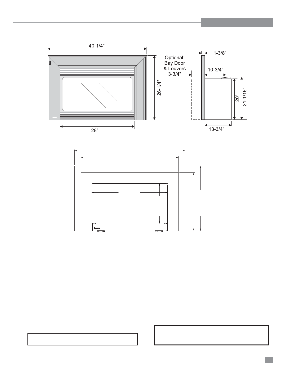
Note: Oversize faceplate is 44" x 28"
40-3/4” (1036mm)
35-15/16” (912mm)
DIMENSIONSDIMENSIONS
27-7/8” (708mm)
23-15/16” (607mm)
14-5/8” (371mm)
21-15/32” (545mm)
Low Profi le Faceplate Dimensions
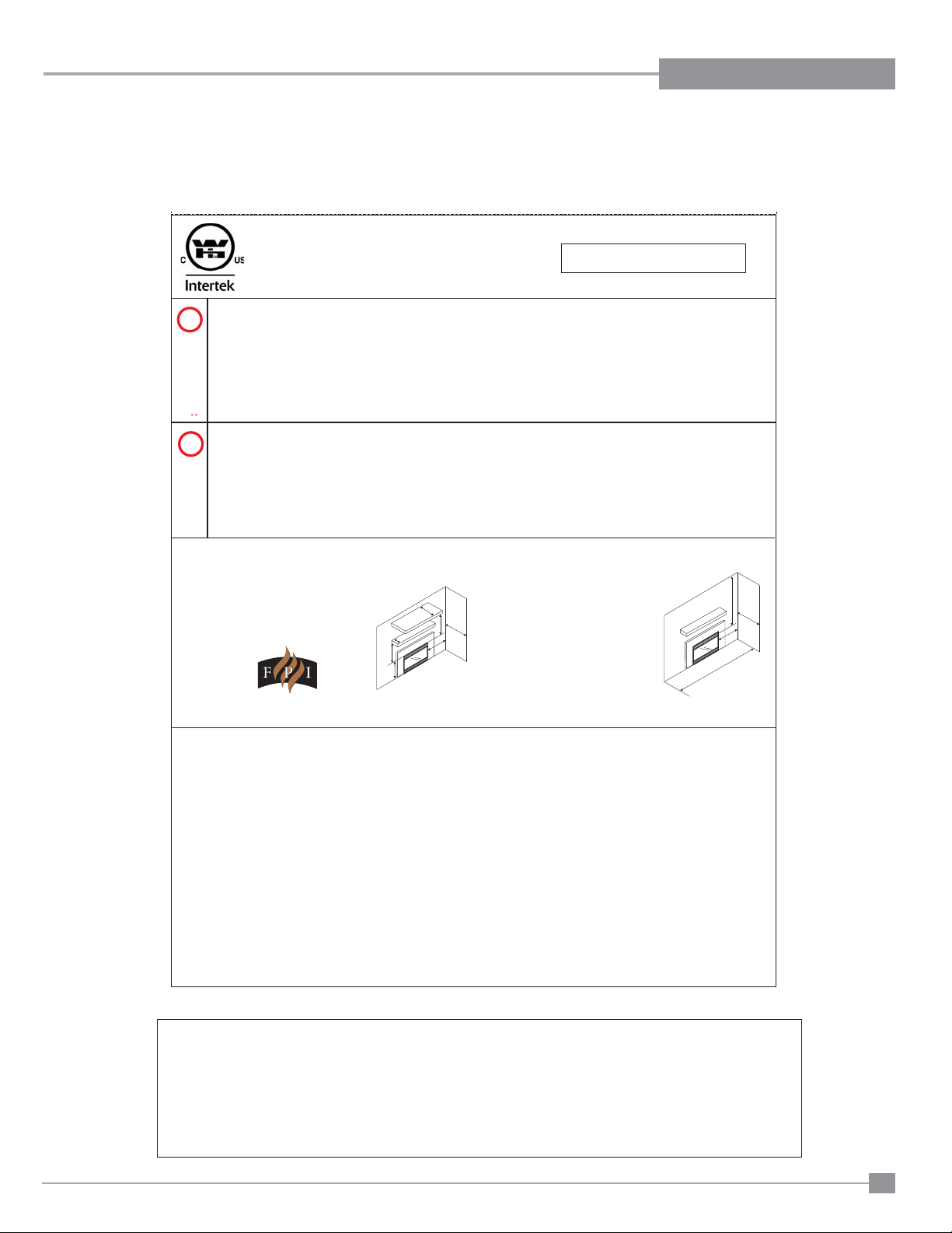
INFORMATION FOR MOBILE/MANUFACTURED HOMES AFTER FIRST SALE
This FPI product has been tested and listed by Warnock Hersey as a Direct Vent Wall Furnace to the following standards: CAN/
CGA-2.17-M91, and ANSI Z21.88-2009/CSA 2.33-2009.
This Direct Vent System Appliance must be installed in accordance with the manufacturer's installation instructions and the
Manufactured Home Construction and Safety Standard, Title 24 CFR, Part 3280, or the current Standard of Fire Safety Criteria for
Manufactured Home Installations, Sites, and Communities ANSI/NFPA 501A, and with CAN/CSA Z240-MH Mobile Home Standard
in Canada. See section "Manufactured Mobile Home Additional Requirements" for additional requirements.
This appliance installation must comply with the manufacturer's installation instructions and local codes, if any. In the absence of
local codes follow the current National Fuel Gas Code, ANSI Z223.1 and the current National Electrical Code ANSI/NFPA 70 in the
U.S.A., and the current CAN/CGA B149 Gas Installation Code and the current Canadian Electrical Code CSA C22.1 in Canada.
This FPI Mobile/Manufactured Home Listed appliance
comes factory equipped with a means to secure the unit.
U32E-5 FPI Direct Vent Gas Insert
This FPI Mobile/Manufactured Home listed appliance comes
equipped with a dedicated #8 ground lug to which an 18 gauge
copper wire from the steel chassis ground must be attached.
33

TABLE OF CONTENTS
DIMENSIONS
Unit Dimensions ............................................................3
SAFETY LABEL
Copy of Safety Label .....................................................5
REQUIREMENTS
MA Code - CO Detector.................................................6
INSTALLATION
Important Message ......................................................7
Before You Start ............................................................7
Important Message ......................................................8
For Your Safety ..............................................................8
Specifi cations ................................................................8
Gas Pressure Testing ....................................................8
Installation Into A Solid Fuel Burning Fireplace Or
Factory Built Fireplace ...................................................8
Before You Start ............................................................8
Installation Checklist ......................................................9
Manufactured Mobile Home Additional Requirements ..9
Materials Required ........................................................9
Minimum Fireplace Dimensions ....................................9
Clearances To Combustibles .........................................9
Gas Connection ..........................................................10
Venting.........................................................................10
Flue Liner Installation ..................................................10
Venting.........................................................................11
Gas Pipe Pressure Testing ..........................................11
Gas Insert Aeration System .........................................11
Optional Brick Panel ....................................................11
Log Set Installation ......................................................12
REGENCY Faceplate & Trim Installation ....................16
Standard Flush Door ...................................................17
Optional Flush Trim .....................................................17
Optional Double Screen Doors ....................................17
Flush Louvers ..............................................................17
Bay Louvers.................................................................18
Optional Bay Door .......................................................18
Optional Bay Trim ........................................................18
Conversion from NG to LP ..........................................19
Full Screen doors ........................................................20
Contemporary Faceplate and doorframe installation...22
Low profi le Faceplate installation ................................24
Optional hearth trim installation ...................................26
Hampton® Cast Faceplate Installation .........................27
Hampton® Cast Grill Installation ..................................28
Optional Wall Thermostat ...........................................29
Optional Remote Control ............................................29
Final Check..................................................................29
Battery Installation .......................................................29
GT Remote Installation ................................................30
GTM Remote Installation .............................................31
Wiring Diagrams ..........................................................33
OPERATING INSTRUCTIONS
Lighting Procedure ......................................................34
Shutdown Procedure ...................................................34
Copy Of Lighting Instruction Plate ...............................34
Operating Instructions ................................................35
First Fire ......................................................................35
Automatic Convection Fan Operation.........................35
Normal Operating Sounds Of Gas Appliances ............36
MAINTENANCE
Maintenance Instructions............................................36
Pilot Adjustment ...........................................................37
General Vent Maintenance ..........................................37
Log Replacement ........................................................37
Glass Gasket ...............................................................37
Gold-plated Trim ..........................................................37
Door Glass ..................................................................37
Fan Maintenance .........................................................38
Valve Replacement ......................................................39
PARTS LIST
Main Assembly ............................................................40
Burner Assembly .........................................................41
Bay & Flush Front Assembly .......................................42
Faceplate Assembly ....................................................43
Hampton® Cast - Faceplate Assembly .........................44
Contemporary faceplate and door frame .....................45
Low profi le faceplate ...................................................46
WARRANTY
Warranty .....................................................................47
4
4
U32E-5 FPI Direct Vent Gas Insert
SAFETY LABEL
NATURAL GAS FIREPLACE INSERT:
Factory Equipped For Altitude 0-4500ft. (0-1370m)
Min. supply pressure 5“ WC (1.25 kpa)
Low Setting Man.pressure WC (0.41 kpa)
Max. Manifold pressure 3.5" WC (0.87 kpa)
Orifice size # 37 DMS
Minimum input 19,500 Btu/h (5.71 )
Maximum input 30,000 Btu/h (8.79 kW)
1.6"
kW
Min. supply pressure 11" WC (2.73 kpa)
Low Setting Man. pressure 6.4" WC (1.59 kpa)
Max. Manifold pressure 10" WC (2.48 kpa)
Orifice size # 52 DMS
Minimum input 22,000 Btu/h (6.45 kW)
Maximum input 27,000 Btu/h (7.91 kW)
PROPANE GAS FIREPLACE INSERT:
Factory Equipped For Altitude 0-4500ft. (0-1370m)
MODEL U32E-NG5
MODEL U32E-LP5
Model/Modele:
U32E-NG5
918-847
Max. Mantel depth M 12” (305mm)
Max. Mantel height N 17" (432mm)
Min. Mantel depth O 3-1/2" (89mm)
Min. Mantel height P 13" (330mm)
Floor to top of unit Q 20" (508mm)
* No Hearth required
Mantel Clearances
L
N
M
O
P
Q
DO NOT REMOVE THIS LABEL /
NE PAS ENLEVER CETTE ETIQUETTE
Serial No. / No de serie
This appliance must be installed in accordance with local codes, if any; if none, follow the National Fuel Gas Code, ANSI Z223.1, or Natural Gas and
Propane Installation Code, CSA B149.1.
This appliance must be installed in accordance with the Standard CAN/CSA Z240 MH, Mobile Housing, in Canada, or with the Manufactured Home
Construction andSafety Standard, Title 24CFR, Part 3280,in the UnitedStates,or when such astandard is notapplicable, ANSI/NCSBCSA225.1/NFPA
501A, ManufacturedHome InstallationsStandard.
This applianceisonly for usewith the typeof gas indicated onthe rating plateand may beinstalled in anaftermarket,permanently located, manufactured
(mobile) homewhere notprohibited by localcodes. Seeowner'smanual for details.
WARNING. This fireplace hasbeen converted foruse with agas fireplace insertonly and cannotbe used forburning wood or solidfuels unless alloriginal
parts havebeen replaced,and the fireplacere-approved bytheauthority having jurisdiction.
Installer l'appareil selon lescodes ou règlements locaux, ou, en l'absence de tels règlements, selonles codes d'installation ANSIZ223.1, National Fuel
Gas Codeou CSA-B149.1en vigueur.
Installer l'appareil selon la norme CAN/CSA-Z240,Série MM, Maison mobiles ou CAN/CSA-Z240 VC,Véhicules de camping, ou lanorme 24 CFR Part
3280, Manufactured Home Construction and Safety Standard. Si ces normes ne sont pas pertinentes, utilisez la norme ANSI/NCSBCS A225.1/NFPA
501A, ManufacturedHome InstallationsStandard.
AVERTISSEMENT : Ce foyer a été converti pour utilisation avec un foyer au gaz encastrable et ne peut être utiliser pour brûler du bois ou d'autres
combustibles solidesà moinsque toutes lespièces d'origineaientété remplacées et quelefoyerait été approuvé denouveauparl'autorité compétente.
For usewith glassdoors certified withthe applianceonly
This ventedgas fireplaceheater is notfor usewith air filters. Ne pasutiliser defiltreà air avec cefoyeraugaz à évacuation.
Cet appareil doit être utilize uniquement avec le type de gaz indiqué sur la plaque signalétique. Cet appareil peut être installé dans une maison
préfabriquée ou mobile (É.-U. seulement) installée à demeure si les règlements locaux le permettent. Voir la notice de l'utilisateur pour plus de
renseignements. Cetappareil nepeut pas êtreutilisé avecd'autresgaz sauf si unetroussedeconversion certifiée est fournie.
Pour utilisationuniquement avecles portes enverre certifiéesavecl'appareil
Listed:
Certified for/Certifi e pour:
Tested to:
WN# 16513
CANADA and U.S.A.
CGA-2.17-M91, ANSI Z21.88-2009 / CSA 2.33-2009
VENTED GAS FIREPLACE HEATER
/ FOYER AU GAZ À ÉVACUATION
é
VENTED GAS FIREPLACE HEATER - NOT FOR USE WITH SOLID FUELS. /
NE PAS UTILISER AVEC DUCOMBUSTIBLE SOLIDE.
FOYER AU
GAZ À ÉVACUATION -
Model/Modele:
U32E-LP5
Minimum Clearances to Combustibles
from Insert
Side wall A 10" (255mm)
Ceiling B 47-1/2" (1205mm)
Alcove Width K 48" (1220mm)
Max. Alcove Depth L 36" (915mm)
K
L
A
B
357
Pression d'allimentation minimum
Pression la tubulure d' chappement basse
Pression la tubulure d' chappement lev e
Dimensions de l'orifice
D bit Calorifique minimum
D bit Calorifique maximum
à
à
é
ééé
é
é
ÉÉQUIP A L'UISINE POUR GAZ PROPANE
ÉÉQUIP A L'UISINE POUR GAZ NATURAL
FPI Fireplace Products International Ltd.,
Delta BC, CANADA
Pression d'allimentation minimum
Pression la tubulure d' chappement basse
Pression la tubulure d' chappement lev e
Dimensions de l'orifice
D bit Calorifique minimum
D bit Calorifique maximum
à
à
é
ééé
é
é
MADE IN CANADA /FABRIQUE AU CANADA
This is a copy of the labels that accompany each U32E-5 Gas Insert.
We have printed a copy of the contents here for your review. The safety
label is located on a plate inside the base of the unit visible when the
bottom louver is opened.
NOTE: FPI units are constantly being improved. Check the label
on the unit and if there is a difference, the label on the unit is the
correct one.
For the State of Massachusetts, installation and repair must be done by a plumber or gasfi tter licensed in the Commonwealth of
Massachusetts.
For the State of Massachusetts, fl exible connectors shall not exceed 36 inches in length.
For the State of Massachusetts, the appliances individual manual shut-off must be a t-handle type valve.
The State of Massachusetts requires the installation of a carbon monoxide alarm in accordance with NFPA 720 and a CO alarm with
battery back up in the same room where the gas appliance is installed.
U32E-5 FPI Direct Vent Gas Insert
5

REQUIREMENTS
MA Code - CO Detector
(for the State of Massachusetts only)
5.08: Modifications to NFPA-54, Chapter 10
(2) Revise 10.8.3 by adding the following additional requirements:
(a) For all side wall horizontally vented gas fueled equipment installed in every dwelling, building or structure used in whole or in part for
residential purposes, including those owned or operated by the Commonwealth and where the side wall exhaust vent termination is less than
seven (7) feet above finished grade in the area of the venting, including but not limited to decks and porches, the following requirements shall
be satisfied:
1. INSTALLATION OF CARBON MONOXIDE DETECTORS. At the time of installation of the side wall horizontal vented gas fueled
equipment, the installing plumber or gasfitter shall observe that a hard wired carbon monoxide detector with an alarm and battery back-up is
installed on the floor level where the gas equipment is to be installed. In addition, the installing plumber or gasfitter shall observe that a battery
operated or hard wired carbon monoxide detector with an alarm is installed on each additional level of the dwelling, building or structure
served by the side wall horizontal vented gas fueled equipment. It shall be the responsibility of the property owner to secure the services of
qualified licensed professionals for the installation of hard wired carbon monoxide detectors
a. In the event that the side wall horizontally vented gas fueled equipment is installed in a crawl space or an attic, the hard wired carbon
monoxide detector with alarm and battery back-up may be installed on the next adjacent floor level.
b. In the event that the requirements of this subdivision can not be met at the time of completion of installation, the owner shall have a period of
thirty (30) days to comply with the above requirements; provided, however, that during said thirty (30) day period, a battery operated carbon
monoxide detector with an alarm shall be installed.
2. APPROVED CARBON MONOXIDE DETECTORS. Each carbon monoxide detector as required in accordance with the above provisions
shall comply with NFPA 720 and be ANSI/UL 2034 listed and IAS certified.
3. SIGNAGE. A metal or plastic identification plate shall be permanently mounted to the exterior of the building at a minimum height of eight
(8) feet above grade directly in line with the exhaust vent terminal for the horizontally vented gas fueled heating appliance or equipment. The
sign shall read, in print size no less than one-half (1/2) inch in size, "GAS VENT DIRECTLY BELOW. KEEP CLEAR OF ALL
OBSTRUCTIONS".
4. INSPECTION. The state or local gas inspector of the side wall horizontally vented gas fueled equipment shall not approve the installation
unless, upon inspection, the inspector observes carbon monoxide detectors and signage installed in accordance with the provisions of 248 CMR
5.08(2)(a)1 through 4.
(b) EXEMPTIONS: The following equipment is exempt from 248 CMR 5.08(2)(a)1 through 4:
1. The equipment listed in Chapter 10 entitled "Equipment Not Required To Be Vented" in the most current edition of NFPA 54 as adopted by
the Board; and
2. Product Approved side wall horizontally vented gas fueled equipment installed in a room or structure separate from the dwelling, building or
structure used in whole or in part for residential purposes.
(c) MANUFACTURER REQUIREMENTS - GAS EQUIPMENT VENTING SYSTEM PROVIDED. When the manufacturer of Product
Approved side wall horizontally vented gas equipment provides a venting system design or venting system components with the equipment, the
instructions provided by the manufacturer for installation of the equipment and the venting system shall include:
1. Detailed instructions for the installation of the venting system design or the venting system components; and
2. A complete parts list for the venting system design or venting system.
(d) MANUFACTURER REQUIREMENTS - GAS EQUIPMENT VENTING SYSTEM NOT PROVIDED. When the manufacturer of a
Product Approved side wall horizontally vented gas fueled equipment does not provide the parts for venting the flue gases, but identifies
"special venting systems", the following requirements shall be satisfied by the manufacturer:
1. The referenced "special venting system" instructions shall be included with the appliance or equipment installation instructions; and
2. The "special venting systems" shall be Product Approved by the Board, and the instructions for that system shall include a parts list and
detailed installation instructions.
(e) A copy of all installation instructions for all Product Approved side wall horizontally vented gas fueled equipment, all venting instructions,
all parts lists for venting instructions, and/or all venting design instructions shall remain with the appliance or equipment at the completion of
the installation.
6
U32E-5 FPI Direct Vent Gas Insert
INSTALLATION
IMPORTANT MESSAGE
SAVE THESE
INSTRUCTIONS
The U32E-5 Gas Insert must be installed in
accordance with these instructions. Carefully read
all the instructions in this manual fi rst. Consult the
"authority having jurisdiction" to determine the need
for a permit prior to starting the installation. It is the
responsibility of the installer to ensure this fi replace
is installed in compliance with manufacturers
instructions and all applicable codes.
BEFORE YOU ST ART
Safe installation and operation of this appliance
requires common sense, however, we are required
by the Canadian Safety Standards and ANSI
Standards to make you aware of the following:
INSTALLATION AND REPAIR SHOULD
BE DONE BY AN AUTHORIZED
SERVICE PERSON. THE APPLIANCE
SHOULD BE INSPECTED BEFORE
USE AND AT LEAST ANNUALLY BY A
PROFESSIONAL SERVICE PERSON.
MORE FREQUENT CLEANING MAY
BE REQUIRED DUE TO EXCESSIVE
LINT FROM CARPETING, BEDDING
MATERIAL, ETC. IT IS IMPERATIVE THAT
CONTROL COMPARTMENTS, BURNERS
AND CIRCULATING AIR PASSAGEWAYS
OF THE APPLIANCE BE KEPT CLEAN.
YOUNG CHILDREN SHOULD BE CAREFULLY SUPERVISED WHEN THEY ARE
IN THE SAME AREA AS THE APPLIANCE. TODDLERS, YOUNG CHILDREN
AND OTHERS MAY BE SUSCEPTIBLE
TO ACCIDENTAL CONTACT BURNS. A
PHYSICAL BARRIERS IS RECOMMENDED IF THERE ARE AT RISK INDIVIDUAL
IN THE HOUSE. TO RESTRICT ACCESS
TO A FIREPLACE OR STOVE, INSTALL
AN ADJUSTABLE SAFETY GATE TO
KEEP TODDLERS, YOUNG CHILDREN
AND OTHER AT RISK INDIVIDUALS OUT
OF THE ROOM AND AWAY FROM HOT
SURFACES.
CLOTHING OR OTHER FLAMMABLE
MATERIAL SHOULD NOT BE PLACED
ON OR NEAR THE APPLIANCE.
DUE TO HIGH TEMPERATURES, THE
APPLIANCE SHOULD BE LOCATED
OUT OF TRAFFIC AND AWAY FROM
FURNITURE AND DRAPERIES.
WARNING: FAILURE TO INSTALL THIS
APPLIANCE CORRECTLY WILL VOID
YOUR WARRANTY AND MAY CAUSE A
SERIOUS HOUSE FIRE.
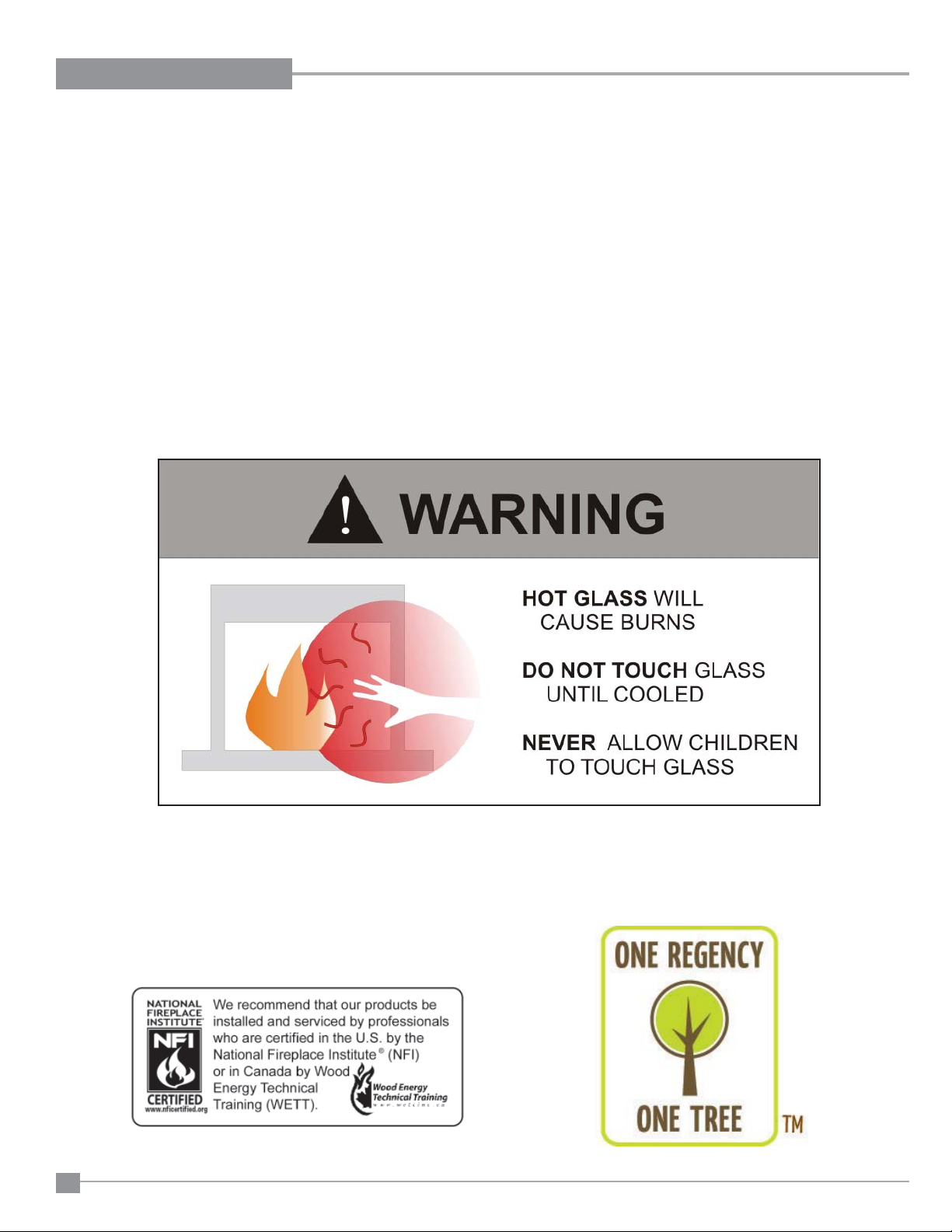
CHILDREN AND ADULTS SHOULD BE
ALERTED TO THE HAZARDS OF HIGH
SURFACE TEMPERATURES, ESPECIALLY THE FIREPLACE GLASS, AND
SHOULD STAY AWAY TO AVOID BURNS
OR CLOTHING IGNITION.
U32E-5 FPI Direct Vent Gas Insert
7

INSTALLATION
IMPORTANT MESSAGE
SAVE THESE
INSTRUCTIONS
The FPI Gas Insert must be installed in
accordance with these instructions. Carefully
read all the instructions in this manual fi rst.
Consult the building authority having jurisdiction
to determine the need for a permit prior to starting
the installation.
NOTE: Failure to follow the instructions could
cause a malfunction of the heater which could
result in death, serious bodily injury, and/
or property damage. Failure to follow these
instructions may also void your fi re insurance
and/or warranty.
FOR YOUR SAFETY
This appliance requires air for proper combustion.
Always provide adequate combustion and
ventilation air. Follow instructions and
information in CAN/CGA B149 (in Canada) or
the National Fuel Gas Code ANSI Z223.1 (in the
USA), regarding requirements for combustion
and ventilation air.
SPECIFICATIONS
At pressures over 1/2 psig, the pipe to the unit
must be disconnected.
Gas Input Capacity:
Natural Gas 30,000 Btu/h
Propane 27,000 Btu/h
Min. Input
Natural Gas 19,500 Btu/h
Propane 22,000 Btu/h
Fuels: Approved for use with both natural gas,
and propane. Approved as is for use at 0' to
4,500' (0-1370m).
Electrical: 120V A.C. system.
Circulation Fan: Variable speed, 110 CFM.
Log Set: Ceramic fi bre, 7 per set.
Vent System: 3" co-linear aluminum fl ex.
The effi ciency rating of the appliance is a
product thermal effi ciency rating determined
under continuous operating conditions and was
determined independent of any installed system.
GAS PRESSURE
TESTING
The appliance must be isolated from the gas supply piping system by closing its individual manual
shut off valve during any pressure testing of the
gas supply piping system at test pressures equal
to or less than
1/2 psig. (3.45 kPa).
INSTALLATION INTO A
SOLID FUEL BURNING
FIREPLACE OR
FACTORY BUILT
FIREPLACE
The U32E-5 Gas Inserts have been tested and
approved to be vented into any masonry fi replace
or approved solid fuel burning factory built fi replace
that will allow the insert to physically fi t into the
fi rebox. Refer to "Minimum Fireplace Dimensions"
section for minimum fi replace clearances.
If the factory built fi replace* height is too low for
your Insert, you may remove the smoke baffl e
plate, damper, refractory (fi rebricks), glass doors,
screen rails, screen mesh and log grates from the
factory built fi replace as long as these items are
saved and are reinstalled in the event that the
Insert is removed.
Smoke shelves, shields and baffl es may be
removed if attached by mechanical fasteners. If any
part is removed it must not weaken the structural
integrity of the factory built fi replace.
NOTE: Any alterations made to the listed solid fuel
burning factory built fi replace may void the listing
of the fi replace.
*Check with your local inspector before commencing
with this installation.
Installer must mechanically attach the supplied
label to the inside of the fi rebox of the fi replace
into which the gas fi replace insert is installed.
"WARNING: This fireplace has been
converted for use with a gas fi replace insert
only and cannot be used for burning wood or
solid fuels unless all original parts have been
replaced, and the fi replace re-approved by
the authority having jurisdiction."
BEFORE YOU ST ART
Safe installation and operation of this appliance
requires common sense, however, we are required
by the Canadian Safety Standards and ANSI Standards to make you aware of the following:
General Safety Information
1) The appliance installation must conform
with local codes or in the absence of local
codes, with CAN/CGA B149 (in Canada) or
the National Fuel Gas Code ANSI Z223.1 in
the U.S.A. This appliance should be installed
by a qualifi ed gas fi tter technician only.
2) Installation and repair should be done
by a qualifi ed service person.
3) The appliance should be inspected before
use and at least annually by a professional
service person. More frequent cleaning
may be required due to excessive lint from
carpeting, bedding material, animal hair, etc.
It is imperative that control compartments,
burners and circulating air passageways of
the appliance be kept clean.
4) See general construction and assembly
instructions. This appliance may only be
installed in a vented, noncombustible
fi replace.
5) This appliance is Listed for bedroom
installations when used with a Listed Millivolt
Thermostat. Some areas may have further
requirements, check local codes before
installation.
6) Always connect this insert to a vent system
venting to the outside of the building
envelope. Never vent to another room or
inside a building. Make sure that the vent
is properly sized and is of adequate height
to provide the proper draft.
7) Inspect the venting system annually for
blockage and any signs of deterioration.
8) Any glass removed for servicing must be
replaced prior to operating the appliance.
9) To prevent injury, do not allow anyone who
is unfamiliar with the operation to use the
fi replace.
10) Due to high temperatures, the appliance
should be located out of high traffi c areas
and away from furniture and draperies.
Children and adults should be alerted to
the hazards of high surface temperatures,
especially the fi replace glass and gold
trims, and should stay away to avoid burns
or clothing ignition. Young children should
be carefully supervised when they are in
the same room as the appliance. Clothing
or other fl ammable material should not be
placed on or near the appliance.
Emissions from burning wood or gas could
contain chemicals known to the State of
California to cause cancer, birth defects or
other reproductive harm.
8
U32E-5 FPI Direct Vent Gas Insert
INSTALLATION
INSTALLATION
CHECKLIST
Before installing vent system ensure that the
damper plate is open and secure to prevent the
damper plate from falling down and crushing
the liner.
The FPI Gas Insert is installed as listed.
1) Check all clearances to combustibles, (Refer
to sections "Minimum Fireplace Dimensions
and Clearances to Combustibles)
2) Make the gas connection. (Refer to section
"Gas Connection")
3) Install the 3" flue liner to the sliding
connector plate. (Refer to section "Flue
Liner Installation.")
4) Slide the unit half way into the fi replace.
5) Pull the vent connector plate through the
tapered brackets and fasten to the front plate.
Refer to section "Flue Liner Installation.")
6) Slide the unit fully into the fi replace.
7) Test gas pressure (Refer to section "Gas
Pipe Pressure Testing"). Check aeration
system (Refer to section "Gas Insert Aeration
System").
8) Install 4-AA batteries into the battery pack.
Batteries must be installed to operate the
burner switch.
9) Install standard and optional features. Refer
to the following sections:
a. Brick Panel
b. Log Set
c. Faceplate & Trim
d. Standard Flush Door
e. Flush Trim
f. Double Screen Door
g. Flush Louvers
h. Bay Louvers
i. Bay Door
j. Bay Trim
k. Full Screen Doors
l. Hampton Cast Faceplate
m. Hampton Cast Grills
n. The Kensington Front
o. Wall Thermostat
p. Remote Control
10) Final check: Before leaving this unit with the
customer, the installer must ensure that the
appliance is fi ring correctly. This includes:
a) Clocking the appliance to ensure the
correct fi ring rate.
b) Adjusting the primary air, if required, to
ensure that the fl ame does not carbon.
See "Gas Insert Aeration System"
section.
c) Ensuring that the appliance is venting
correctly.
U32E-5 FPI Direct Vent Gas Insert
MANUFACTURED
MOBILE HOME
ADDITIONAL
REQUIREMENTS
1) Ensure that structural members are not cut
or weakened during installation.
2) Ensure proper grounding using the #8
ground lug provided.
3) Appliance must be anchored to the fl oor
with the supplied anchoring methods.
MATERIALS REQUIRED
No electrical power supply is required for the gas
control to operate. A 120 V olt AC power cord is
hooked up to the fan. Plug the 3 wire cord into
a suitable receptacle. Do not cut the ground
terminal off under any circumstances. When
connected with 120 volts, the appliance must
be electrically grounded in accordance with
local codes, current version of CSA C22.1 (in
Canada) or in the absence of local codes, with the
National Electrical Code ANSI/NFPA 70-1987.
MINIMUM FIREPLACE
DIMENSIONS
The minimum fi replace clearances & dimensions
for the FPI gas insert are shown in the following
diagrams:
A
B
C
D
E
Regency
Countour
Faceplate
Regency
Molded
Faceplate
Palace
Front
Hampton
Cast
Faceplate
Full
Screen
Doors
Max Lentil
Bar DepthAHeightBDepth
9" 22" 14" 22-1/2" 26-1/2"
10" 22" 15" 22-1/2" 29"
10" 22" 15" 22-1/2" 29"
9" 22" 14" 22-1/2" 26-1/2"
9" 22" 14" 22-1/2" 26-1/2"
Width
(rear)
C
D
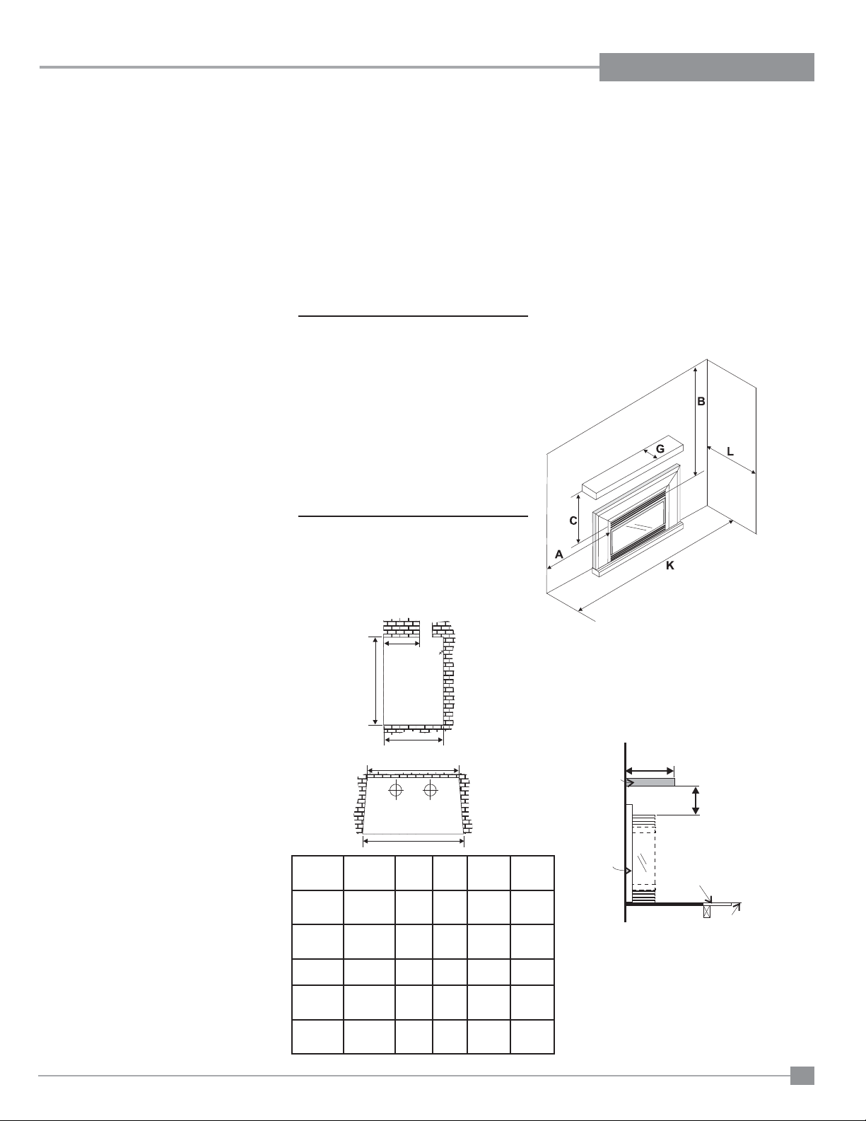
CLEARANCES TO
COMBUSTIBLES
Minimum Clearances to Combustibles
From Unit
Sides A 10" / 255 mm
Ceiling B 47.5" / 1205 mm
Mantel C see Dia. 2 & 3
Max. Mantle Depth G 12" / 305 mm
(see Dia. 2)
Min. Alcove Width K 48" / 1220 mm
Max. Alcove Depth L 36" / 915 mm
*No Hearth Required
Diagram 1
Combustible Mantel Clearances
with Bay & Flush Louvers in
Masonry and Factory Built
Fireplace Installation
12" Max.
G
C
Combustible
Flooring
Flush
with
Floor
Diagram 2
Width
(front)
E
Mantle
Faceplate
9
INSTALLATION
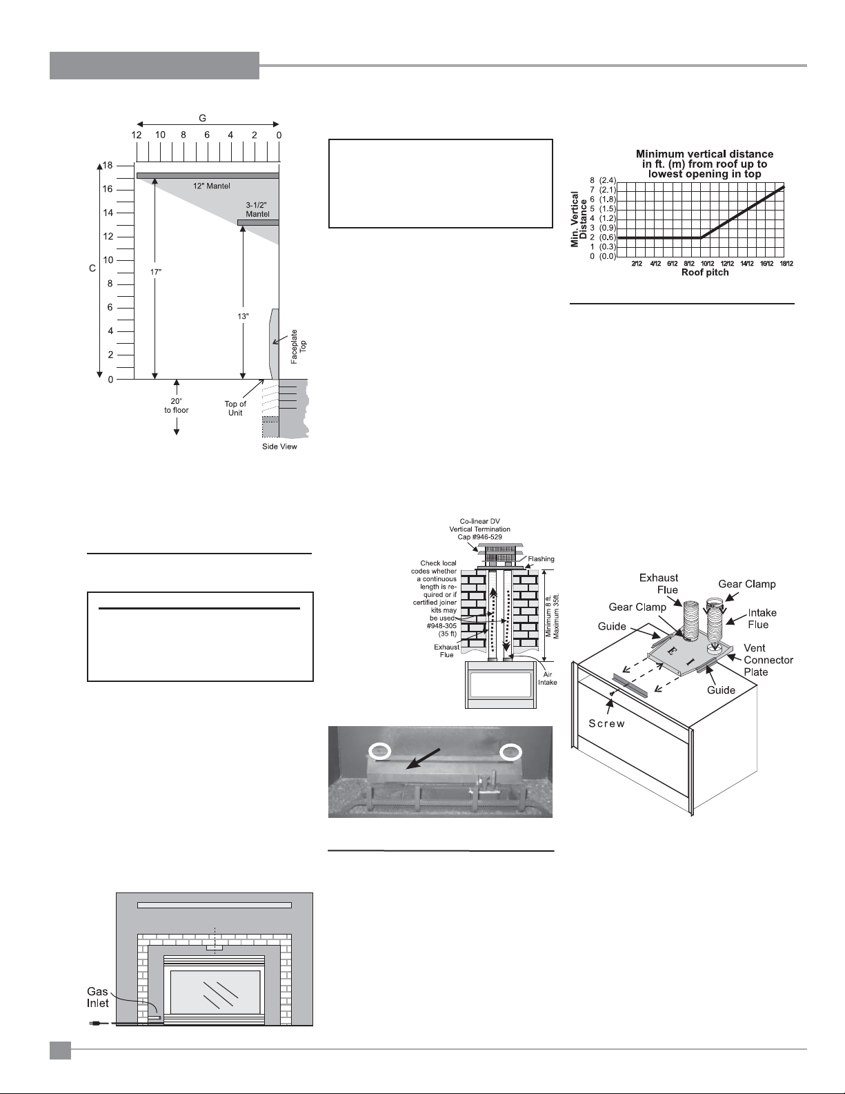
Diagram 3
Note: A noncombustible mantel may be
installed at a lower height if the
framing is made of metal studs
covered with a noncombustible
board.
GAS CONNECTION
GAS CONNECTION WARNING:
Only persons licensed to work
with gas piping may make the
necessary gas connections
to this appliance.
1) If the appliance is to be installed into an
existing chimney system, thoroughly clean
the masonry or factory built fi replace.
2) The appliance is provided with an opening on
the left hand side of the control compartment.
A 3/8" NPT gas supply pipe must be brought
near this inlet hole.
VENTING
THE APPLIANCE MUST NOT BE
CONNECTED TO A
CHIMNEY FLUE SERVING A
SEPARATE SOLID FUEL
BURNING APPLIANCE.
This appliance is designed to be attached to
two 3" (76mm) co-linear aluminium fl ex running
the full length of the chimney. The fl ue length
must be a minimum length of 8 ' (2.44m) and
a maximum of 35' (10.7m). See chart below for
minimum distances from roof. Periodically check
that the vent is unrestricted.
Masonry chimneys may take various contours
which the fl exible liner will accommodate.
However, keep the fl exible liner as straight as
possible, avoid unnecessary bending.
The Air Intake pipe must be attached to the inlet
air collar of the termination cap.
Part # Description
948-305 3" Flex - 35 ft.
946-529 Co-linear DV Vertical
Termination Cap
Important:
Air Defl ector
(Part #420-119) is
required for all
LP installations.
For Natural Gas
installations -the
air defl ector
is required when
venting is a minimum of 15ft
to a maximum of
35ft.
Not required on
NG if venting is
between
8ft. to 14.99ft
Air Defl ector
The Air Intake pipe must be attached to the
inlet air collar of the termination cap.
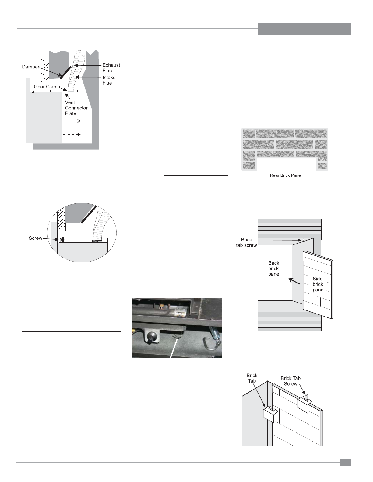
FLUE LINER
INSTALLATION
1) Cut the fl ex liner as required.
2) Mark the end of one liner to indicate Inlet.
3) Connect the other end of the above liner to
the inlet side of the termination adaptor, seal
connection with high temperature silicone.
Secure with gear clamp.
4) Connect the 2nd liner to the exhaust side
of the adaptor, seal connection with high
temperature silicone. Secure with gear
clamp.
5) Install fl ashing.
3) Locate the center point where the vent
will pass through the chimney above the
appliance. Move the appliance into the
exact location where it is to be installed.
Ensure that the Insert is level.
10
Install the air defl ector to the back wall of the fi rebox
using 2 screws.
Alternate Approved Caps
46dva-VC Vertical Termination Cap
46dva-VCH High Wind Cap
46dva-GK 3" Co-linear Adaptor with fl ashing
In areas of consistently high winds, we
recommend using the Simpson Dura-Vent
System (46dva-GK adapter and 46dva-VCH
high-wind cap).
The Air Intake pipe must be attached to the inlet
air collar of the termination cap.
6) Insert both liners into chimney, passing
through the damper opening.
7) Install termination cap.
8) Connect the marked end of the liner to
the inlet collar of the vent connector plate
marked with an "I", seal connection with
high temperature silicone. Secure with gear
clamp.
U32E-5 FPI Direct Vent Gas Insert
INSTALLATION
Be careful not to damage thermal insula-
tion when sliding on vent connector plate.
This could cause blockage.
VENTING
THE APPLIANCE MUST NOT BE
CONNECTED TO A
CHIMNEY FLUE SERVING A
SEPARATE SOLID FUEL
BURNING APPLIANCE.
This appliance is designed to be attached to
two 3" (76mm) co-linear aluminium fl ex running
the full length of the chimney. The fl ue length
must be a minimum length of 8 ' (2.44m) and
a maximum of 35' (10.7m). See chart below for
minimum distances from roof. Periodically check
that the vent is unrestricted.
GAS PIPE
PRESSURE TESTING
The appliance must be isolated from the gas
supply piping system by closing its individual
manual shut-off valve during any pressure
testing of the gas supply piping system at test
pressures equal to or less than 1/2 psig. (3.45
kPa). Disconnect piping from valve at pressures
over 1/2 psig.
The manifold pressure is controlled by a regulator
built into the gas control, and should be checked
at the pressure test point.
Note: To properly check gas pressure, both
inlet and manifold pressures should
be checked using the valve pressure
ports on the valve.
1) Make sure the valve is in the "OFF"
position.
2) Loosen the "IN" and/or "OUT" pressure
tap(s), turning counterclockwise with a 1/8"
wide fl at screwdriver.
3) Attach manometer to "IN" and/or "OUT"
pressure tap(s) using a 5/16" ID hose.
4) Light the pilot and turn the valve to "ON"
position.
5) The pressure check should be carried out
with the unit burning and the setting should
be within the limits specifi ed on the safety
label.
6) When fi nished reading manometer, turn
off the gas valve, disconnect the hose and
tighten the screw (clockwise) with a 1/8" fl at
screwdriver. Note: Screw should be snug,
but do not over tighten.
GAS INSERT
AERATION SYSTEM
The air shutter can be adjusted by moving the
adjusting wire up or down. The wire is accessed
through the bottom louver opening. Open the air
shutter for a blue fl ame or close for a yellower
fl ame. The burner aeration is factory set but
may need adjusting due to either the local gas
supply or altitude.
Minimum Air Shutter Opening:
3/16" Natural Gas
1/4" Propane
Aeration Adjustment Wire
PULL= Open
PUSH = Close
CAUTION: Carbon will be produced if air shutter
is closed too much.
Note: any damage due to carboning resulting
from improperly setting the aeration controls
is NOT covered under warranty.
Note: Aeration Adjustment should only
be performed by an authorized FPI
Installer at the time of installation or
service.
OPTIONAL
BRICK PANEL
1) Unwrap the brick pattern panels from the
protective wrapping.
2) Remove the glass front if it is already
installed, see "Standard Flush Door"
section.
3) Put the rear brick panel fl at against the back
of the unit.
4) Before installing the side brick panels, loosen
the screws for the brick tabs enough so that
you can slide the brick tabs on to the screws
easily but that the tabs are secure. For the
location of the side brick tab screws see
diagram 1.
Diagram 1
5) Remove the brick tabs and slide the side
brick panels into position. See diagram 1.
Install the brick tabs. See diagram 2.
Diagram 2
U32E-5 FPI Direct Vent Gas Insert
11
INSTALLATION
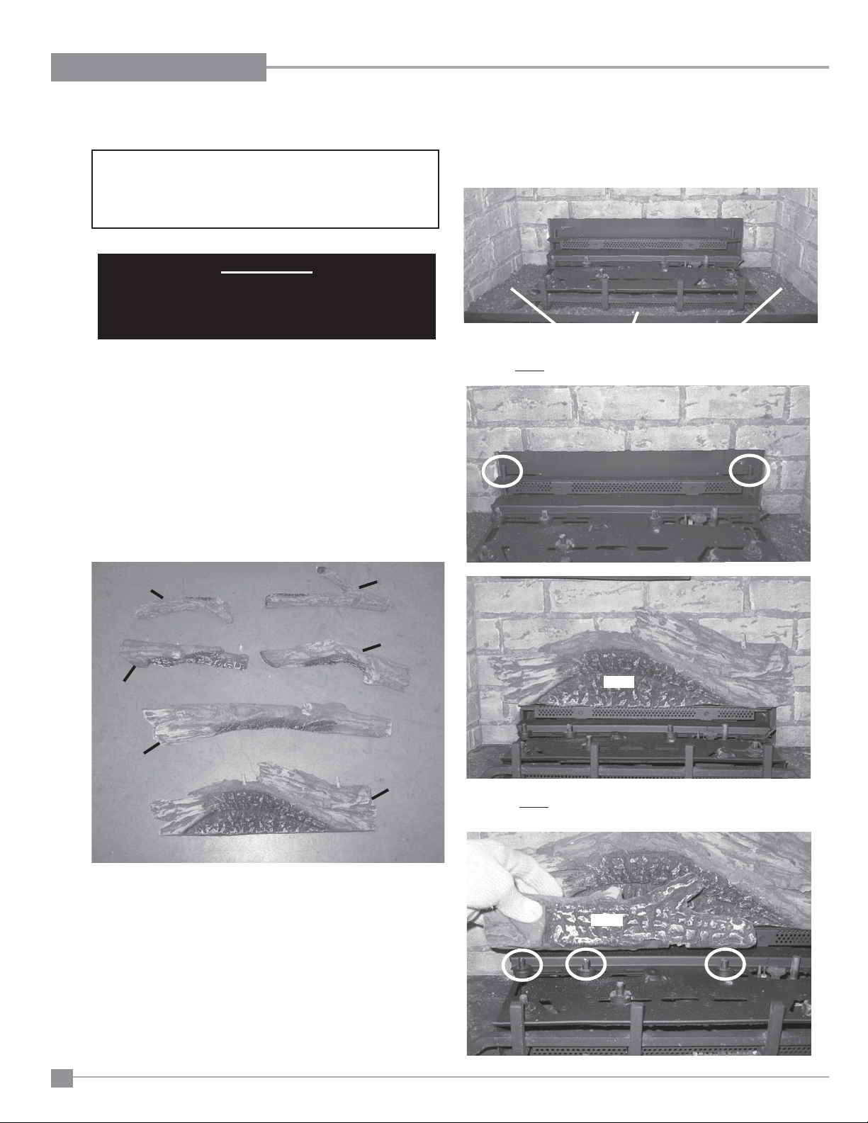
LOG SET INSTALLATION
Read the instructions below carefully and refer to the images.
Dangerous operating conditions may occur if the logs are not
positioned in their correct locations. If the logs are broken
do not use the unit until they are replaced. Broken logs can
interfere with the pilot operation.
IMPORTANT
For LP units the Air Defl ector MUST be installed prior
to log installation. See "Conversion from NG to LP"
section in manual for installation instructions.
Log kit (Part # 425-930) contains the following pieces:
a) 27-31 Rear Log
b) 27-32 Middle Left Log
c) 27-33 Front Log
d) 27-34 Middle Right Log
e) 27-35 Left Log
f) 27-36 Right Log
g) 902-154 Embers Lava
h) 902-179 Vermiculite
i) 902-153 Rock Wool
j) 946-669 Platinum Embers (supplied with packaged manual)
2) Spread vermiculite around the exposed fi rebox base. Then take some
embers and spread them over the vermiculite as shown.
Vermiculite and Embers
3) Fit log 27-31 into the pins on the rear log tray.
27-36
27-32
27-33
1) Carefully remove the logs from the box and unwrap them. The logs
are fragile, handle with care - do not force into position.
27-35
27-34
27-31
27-31
4) Fit log 27-32 into the pins on the middle left hand side of the
burner.
27-32
12
U32E-5 FPI Direct Vent Gas Insert
INSTALLATION
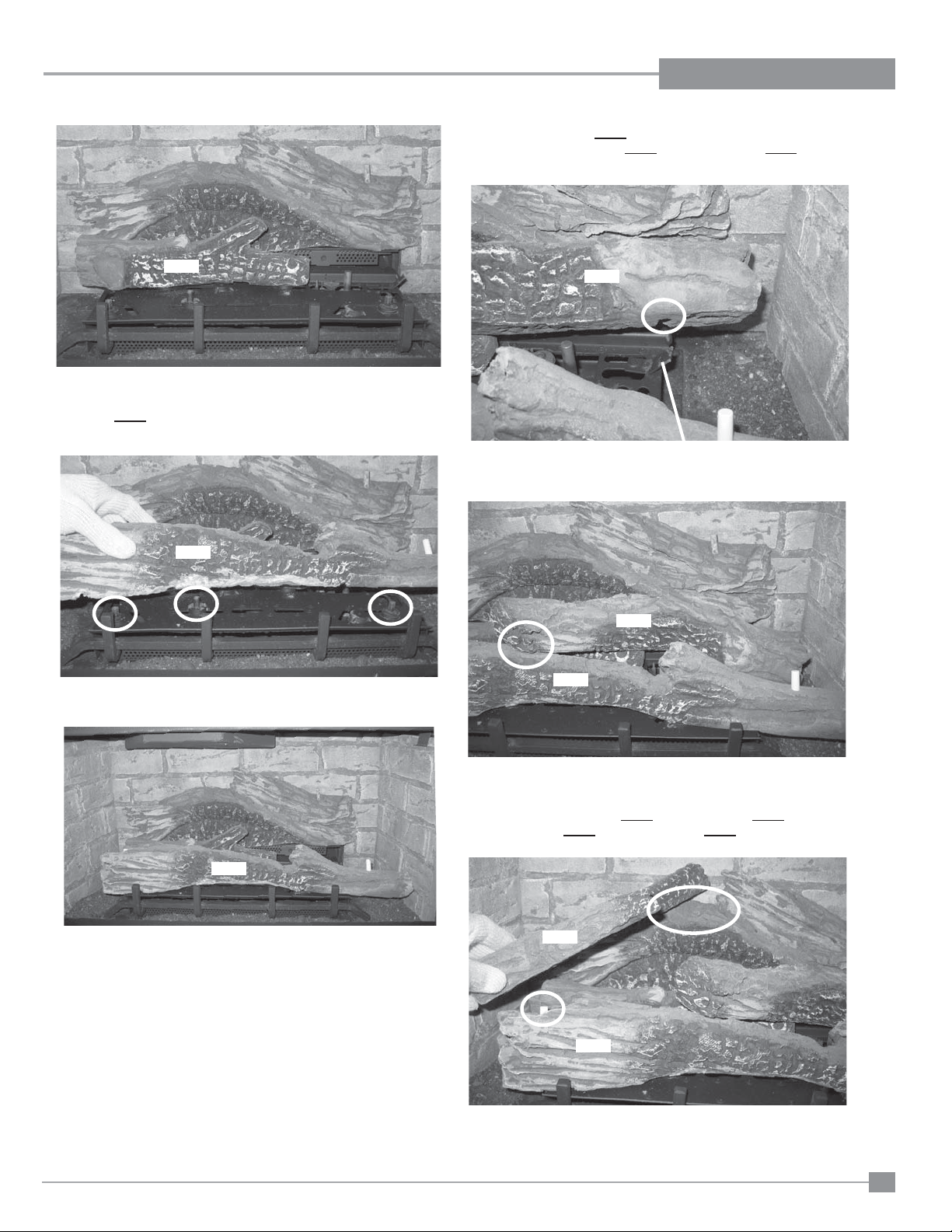
6) Fit the groove in log 27-34 into the tab on the right side of the burner.
Rest the other end of log 27-34 on the notch in log 27-33.
27-32
5) Fit log 27-33 into the pins at the front of the burner.
27-33
27-34
Tab
27-34
27-33
27-33
U32E-5 FPI Direct Vent Gas Insert
7) Fit the bottom end of log 27-35 into the pin in log 27-33 and rest the
top end of log 27-35 on the notch in log 27-31.
27-35
27-33
13
INSTALLATION
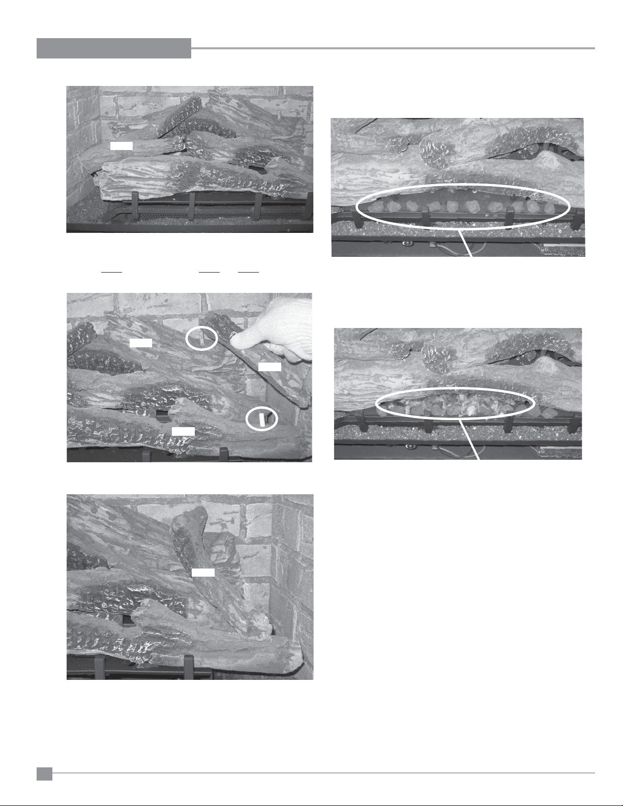
27-35
9) Place embers along the front of the burner as shown. Ensure not to
cover any burner ports.
8) Fit log 27-36 into the pins on logs 27-33 and 27-31.
27-31
27-33
Embers
10) Separate platinum embers and place on the burner just in front of
the logs as shown. Avoid stacking platinum embers.
27-36
Platinum Embers
14
27-36
U32E-5 FPI Direct Vent Gas Insert
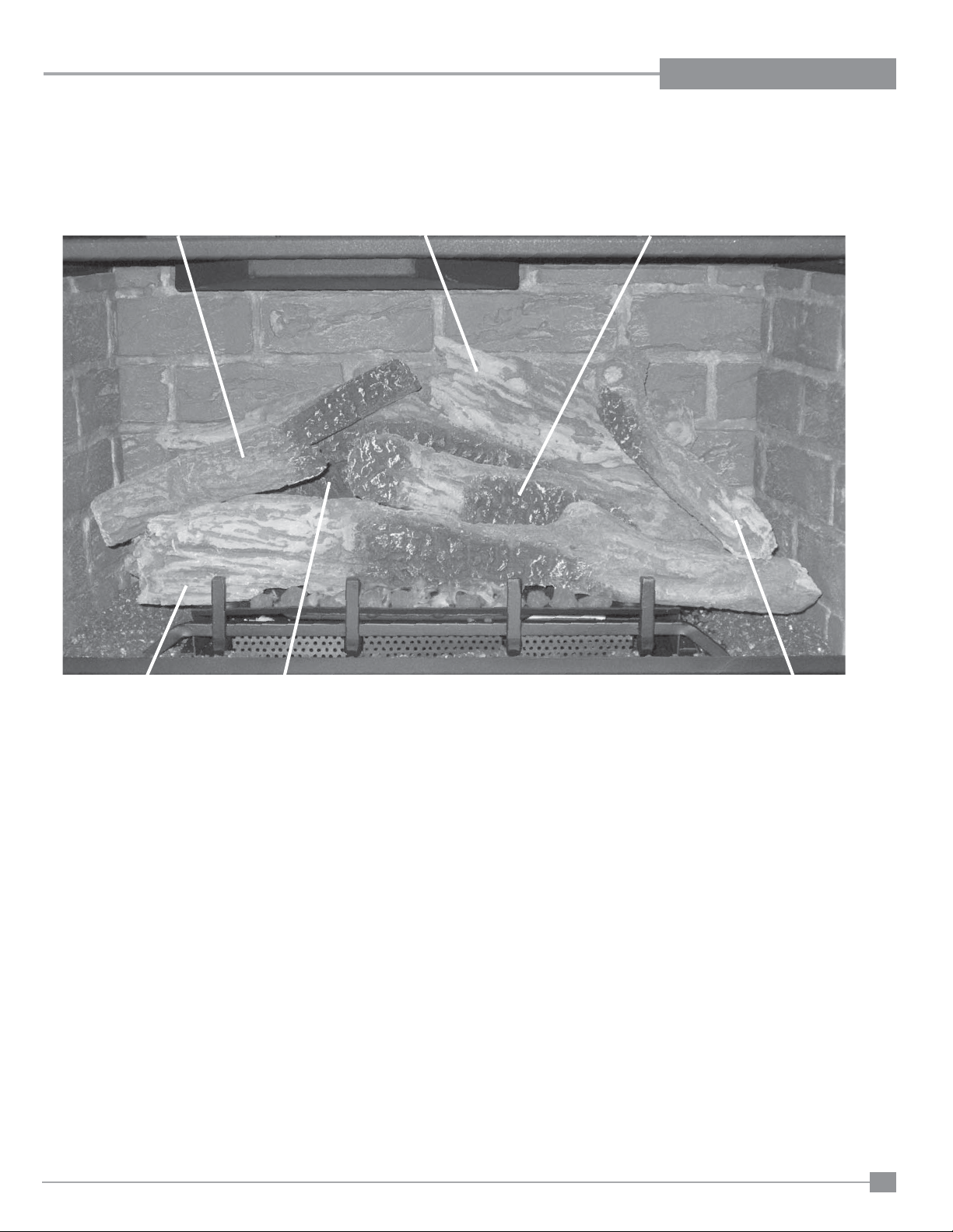
Completed Log Set Installation
INSTALLATION
27-35
27-31
27-34
27-33
27-32
27-36
U32E-5 FPI Direct Vent Gas Insert
15
 Loading...