

Page 1
Owners & Installation Manual
Wood
Fireplace
Insert
Report #219-S-17-2
919-300b
www.regency-fi re.com
MODEL: CI2600/HI400
Installer: Please complete the details on the back cover
and leave this manual with the homeowner.
Homeowner: Please keep these instructions for future reference.
FPI FIREPLACE PRODUCTS INTERNATIONAL LTD. 6988 Venture St., Delta, BC Canada, V4G 1H4
04.16.14
Page 2

2 |
Thank-you for purchasing a REGENCY FIREPLACE PRODUCT.
The pride of workmanship that goes into each of our products will give you years of trouble-free enjoyment. Should you have
any questions about your product that are not covered in this manual, please contact the REGENCY DEALER in your area.
Keep those REGENCY FIRES burning.
SAFETY NOTE: If this wood stove is not properly installed, a house fi re may result. For your safety, follow the installation
instructions, contact local building, fi re offi cials, or authority having jurisdiction about restrictions and installation inspection
requirements in your area.
The following statements are required by the Environmental Protection Agency:
"This manual describes the installation and operation of the Regency CI2600/HI400 catalytic equipped heater. This heater
meets the U.S. ENVIRONMENTAL PROTECTION AGENCY’s emission limits for wood heaters built on or after July 1 1990.
Under specifi c test conditions this heater has been shown to deliver heat at rates ranging from
"This wood heater contains a catalytic combustor, which needs periodic inspection and replacement for proper operation. It
is against the law to operate this wood heater in a manner inconsistent with operating instructions in this manual, or if the
catalytic element is deactivated or removed."
CAUTION: BURN UNTREATED WOOD ONLY. OTHER MATERIALS SUCH AS WOOD PRESERVATIVES, METAL FOILS,
COAL, PLASTIC,GARBAGE, SULPHUR OR OIL MAY DAMAGE THE CATALYST
"This heater is designed to burn natural wood only. Higher effi ciencies and lower emissions generally result when burning
air dried seasoned hardwoods, as compared to softwoods or to green or freshly cut hardwoods."
15165 BTU/hr to 27535 BTU/hr.
DO NOT BURN:
• Treated wood
• Coal
• Garbage
• Cardboard
• Solvents
• Colored Paper
• Trash
The authority having jurisdiction (such as Municipal Building Department, Fire Department, Fire Prevention Bureau, etc.) should be consulted before installation to determine the need to obtain a permit.
This unit must be connected to either a listed factory built chimney suitable for use with solid fuels and conforming to,
UL1777,ULCS635 and ULCS640, or code approved masonry chimney with fl ue liner.
CI2600/HI400 is tested and certifi ed to ULCS-628-93 and UL1482-2011.
SAVE THESE INSTRUCTIONS
CI2600/HI400 | wood insert
Page 3

| 3
Safety Label For CI2600/HI400 ............................................................................................... 4
Dimensions - contemporary faceplate ..................................................................................... 5
Dimensions - low profi le faceplate ........................................................................................... 6
Dimensions - cast faceplate ....................................................................................................7
Before installing your insert ..................................................................................................... 8
Chimney specifi cations ............................................................................................................8
Wood Insert Specifi cations ...................................................................................................... 8
Masonry And Factory Built Fireplace Clearances ..................................................................9
How To Determine If Alternate Floor Protection Materials Are Acceptable ............................. 9
Installing Your Insert .............................................................................................................. 10
Installation Into A Masonry Fireplace ................................................................................................ 12
Step-by-step Installation Into A Factory Built Fireplace ......................................................... 12
Optional cast grill Installation ................................................................................................. 13
Firebrick Assembly ................................................................................................................ 13
Optional backing plate Installation ......................................................................................... 14
Contemporary Faceplate Installation ..................................................................................... 15
Low profi le Faceplate Installation ..........................................................................................17
Cast Faceplate Installation ....................................................................................................19
Optional Fan/Blower Installation ............................................................................................ 20
Removable door handle ......................................................................................................... 23
Bypass handle ....................................................................................................................... 23
Operating instructions............................................................................................................ 24
Draft control ........................................................................................................................... 24
First fi re .................................................................................................................................. 24
Ash disposal .......................................................................................................................... 25
Fan operation ......................................................................................................................... 25
Creosote ................................................................................................................................ 25
Removal for cleaning ............................................................................................................. 25
Ways to prevent and keep unit free of creosote ....................................................................25
Wood storage ........................................................................................................................ 25
Safety guidelines & warnings ................................................................................................26
Catalytic combustor (Part # 106-534) .................................................................................... 27
Provision for catalytic combustor temperature probe ........................................................... 28
Combustor assembly removal / REPLACEMENT: ................................................................ 29
Bypass door gasket replacement ......................................................................................... 30
Door Gasket ..........................................................................................................................32
Glass cleaning ....................................................................................................................... 32
Glass replacement .................................................................................................................32
Glass removal ........................................................................................................................32
Secondary air tube removal / ................................................................................................33
Door catch Adjustment ..........................................................................................................33
Main Assembly ...................................................................................................................... 34
Brick layout ............................................................................................................................ 35
Warranty ................................................................................................................................39
table of contents
http://oee.nrcan.gc.ca/residential/personal/retrofi t-homes/retrofi t-qualify-grant.cfm
CI2600/HI400 | wood insert
Page 4
4 |
INSTALL AND USE ONLY IN ACCORDANCE WITH THE MANUFACTURER'S INSTALLATION AND OPERATING INSTRUCTIONS. INSTALL AND USE ONLY IN
MASONRY FIREPLACE OR FACTORY BUILT FIREPLACE. CONTACT LOCAL BUILDING OR FIRE OFFICIALS ABOUT RESTRICTIONS AND INSTALLATION
INSPECTION IN YOUR AREA.
INSTALLER ET UTILISER SELONS LES INSTRUCTIONS DU FABRICANT. INSTALLER ET UTILISER DANS UN FOYER DE MACONNERIE OU PRÉFABRIQUÉ.
APPELER VOTRE INSPECTEUR DE BÂTIMENT OU LE DÉPARTMENT D’INCENDIE LOCAL POUR LES CODES LOCAUX ET POUR INSPECTÉE
VOTRE INSTALLATION ET FOYER.
LISTED FACTORY BUILT FIREPLACE INSERT
CONSTRUITS EN USINE CHEMINÉE INSERT
CERTIFIED FOR USE IN CANADA AND U.S.A
CERTIFIÉE POUR: CANADA AND U.S.A.
MODEL/ MODÉLE:
CI2600/HI400
TESTED TO: ULC-S628-93 / UL-1482 - 2011
DO NOT REMOVE THIS LABEL
NE PAS ENLEVER CETTE ETQUETTE
429
MINIMUM CLEARANCES TO COMBUSTIBLE MATERIALS (MEASURED FROM TOP/SIDE DOOR)
UN MINIMUM DE DÉGAGEMENT DE MATÉRIAUX COMBUSTIBLES (MESURÉE À PARTIR DU HAUT/PORTE LATÉRALE)
ADJACENT SIDEWALL / LATÉRAL ADJACENT
MANTLE / MANTEAU
TOP FACING/FACE SUPÉRIEUR
SIDE FACING / FACE CÔTÉ
A) 12-3/16 in / 310 mm
B) 21-5/8 in / 549 mm
C) 14 in / 356 mm
D) 7-3/8 in / 187 mm
COMPONENTS REQUIRED FOR INSTALLATION: 6" (152mm) STAINLESS STEEL LINER - LISTED TO: UL1777, ULCS635 OR ULCS640. OPTIONAL COMPONENT: FAN (PART# 106-917), ELECTRICAL RATING: VOLTS 115, 60 HZ, 0.6 AMPS, CONTEMPORARY FACEPLATE, CONTOUR FACEPLATE, CAST FACEPLATE, OFFSET FLUE COLLAR, OR BACKER PLATE.
DANGER: RISK OF ELECTRIC SHOCK. DISCONNECT POWER BEFORE SERVICING UNIT. DO NOT ROUTE POWER CORD UNDER OR IN FRONT OF APPLIANCE. DO NOT CONNECT THIS UNIT TO A
CHIMNEY FLUE SERVICING ANOTHER APPLIANCE. DO NOT REMOVE BRICKS OR MORTAR IN MASONRY FIREPLACE. FOR USE WITH SOLID WOOD FUEL ONLY. DO NOT USE GRATE OR ELEVATE
FIRE. BUILD WOOD FIRE DIRECTLY ON HEARTH. RISK OF SMOKE AND FLAME SPILLAGE, OPERATE ONLY WITH DOORS FULLY CLOSED. OPEN FEED DOOR TO FEED FIRE ONLY. REPLACE
GLASS ONLY WITH CERAMIC GLASS (5MM). INSPECT AND CLEAN CHIMNEY FREQUENTLY. UNDER CERTAIN CONDITIONS OF USE CREOSOTE BUILDUP MAY OCCUR RAPIDLY. DO NOT OVERFIRE, IF INSERT GLOWS, YOU ARE OVER-FIRING. CAUTION: THE COMBUSTOR (PART #106-534 ) IS FRAGILE, HANDLE CAREFULLY. CAUTION: BURNING OF METAL FOILS, COAL, PLASTIC, GARBAGE, SULPHUR AND DIESEL OIL WILL RENDER THE CATALYST IN THE COMBUSTOR INACTIVE. THE PERFORMANCE OF THE CATALYTIC DEVICE OR ITS DURABILITY HAS NOT BEEN EVALUATED AS PART OF THE CERTIFICATION. CAUTION: HOT PARTS-DO NOT OPERATE WITH DOOR REMOVED.
PIÈCES NÉCESSAIRES POUR INSTALLATION : 6" (152MM) CONDUITS EN ACIER INOXYDABLE HOMOLOGUÉ SELON : UL1777, ULCS635 OU ULCS640. COMPOSANT FACULTATIF : VENTILATEUR (PIÈCE 106-917);
CARACTÉRISTIQUES ÉLECTRIQUES ASSIGNÉES : 115 V, 60 HZ, 0,6 A; FAÇADE CONTEMPORAINE, FAÇADE BISEAUTÉE, FAÇADE EN FONTE, BUSE DE CONDUIT DE CHEMINÉE COUDÉ OU PLAQUE DE FIXATION. ATTENTION: RISQUE DU CHOC ÉLECTRIQUE. AVANT DE L'ENTRETIEN, DÉBRANCHER L'APPAREIL. NE PLACEZ PAS LE CORDON D'ALIMENTATION EN FACE OU EN DESSOUS DE L'APPAREIL. NE PAS
ENLEVER DE BRIQUES OU DE MORTIER D’UNE CHEMINÉE DE MAÇONNERIE. N'UTILISER QUE DU COMBUSTIBLE SOLIDE. REMPLACEZ LA VITRE SEULEMENT PAR DU VERRE EN NEOCERAM . NE PAS SURÉLEVER LES BÛCHES NI LES PLACER SUR DES GRILLES. LES DÉPOSER DIRECTEMENT SUR L’ÂTRE. RISQUE DE DÉGAGEMENT DE FUMÉE OU DE FLAMMES : TOUJOURS GARDER LES PORTES BIEN FERMÉES
LORSQUE L’APPAREIL FONCTIONNE. OUVRIR LA PORTE UNIQUEMENT POUR ALIMENTER LE FEU. INSPECTER ET NETTOYER FRÉQUEMMENT LA CHEMINÉE. SELON LE TYPE D’USAGE, LE CRÉOSOTE PEUT
S’ACCUMULER RAPIDEMENT.
NE PAS SURCHAUFFER; SI L’ENCASTRABLE SE MET À ROUGIR, IL S’AGIT D’UNE SURCHAUFFE.
AVERTISSEMENT : LE CATALYSEUR (PIÈCE 106-534) EST FRAGILE ET DOIT ÊTRE MANIPULÉ SOIGNEUSEMENT. LA COMBUSTION DE PAPIER D'ALUMINIUM, DE CHARBON, DE PLASTIQUE, DE DÉCHETS, DE
SOUFFRE OU D’ESSENCE DIESEL RENDRA LE CATALYSEUR INACTIF. NI LE RENDEMENT NI LA DURABILITÉ DU CATALYSEUR N’ONT ÉTÉ ÉVALUÉS DANS LE CADRE DU PROCESSUS D’HOMOLOGATION. RE-
MARQUE: TEMPÉRATURES ÉLEVÉES. NE JAMAIS FAIRE FONCTIONNER L’APPAREIL SI LA PORTE VITRÉE N'EST PAS BIEN EN PLACE.
CAUTION
INSTALL ONLY ON A NON-COMBUSTIBLE HEARTH
COMBUSTIBLE FLOOR MUST BE PROTECTED BY NON-COMBUSTIBLE MATERIAL EXTENDING (E) 18 IN / 457 MM TO FRONT AND (G) 8 IN / 205 MM TO SIDES FROM FUEL DOOR.
IN CANADA, SIDE HEARTH PROTECTION TO BE MEASURED FROM SIDE OF UNIT.
FLOOR PROTECTION NEEDS TO BE WITH R VALUE = 2.13
INSTALLER SUR UN ÂTRE DE MATÉRIAU NOM COMBUSTIBLE SURÉLEVÉ COMBUSTIBLE
ADJACENT. LE PLANCHER COMBUSTIBLE DOIT ÊTRE PROTÉGÉ PAR LE MATÉRIAU NOM
COMBUSTIBLE QUI ÉTENDRE (E) 18 po / 457 MM À L'AVANT ET (G) 8 po / 205 MM SUR LES
CÔTÉS DE LA PORTE DE CARBURANT.
AU CANADA, LA PROTECTION DE FOYER DE CÔTÉ ÊTRE MESURÉE À PARTIR CÔTÉ DE
L'APPAREIL.PROTECTION DE PLANCHER BESOIN D'ÊTRE AVEC LA VALEUR R = 2.13
MADE IN CANADA
919-299a
Manufactured By
:
FIREPLACE PRODUCTS INTERNATIONAL LTD.
6988 VENTURE ST., DELTA, BC V4G 1H4
HOT WHILE IN OPERATION DO NOT
TOUCH. KEEP CHILDREN, CLOTHING AND FURNITURE AWAY. CONTACT MAY CAUSE SKIN BURNS. READ
NAMEPLATE AND INSTRUCTIONS.
UNITED STATES ENVIRONMENTAL
PROTECTION AGENCY
CERTIFIED TO COMPLY WITH
July 1990, PARTICULATE
EMISSION STANDARDS.
MANUFACTURED BY FPI LTD.
SIGNATURE
Jan Feb Mar Apr May June
July Aug Sept Oct Nov Dec
DATE OF
MANUFACTURE
(Duplicate Serial #) 429
2013 2014 2015
Report #219-S-17-2
AVERTISSEMENT
CHAUD PENDANT LE FONCTIONNEMENT. NE PAS TOUCHER.GARDER LES
ENFANTS, LES VÊTEMENTS ET LES
MEUBLES À L’ÉCART.LE CONTACT
AVEC LA PEAU PEUT OCCASIONNER
DES BRÛLURES. LIRE LA PLAQUE
SIGNALÉTIQUE ET LES INSTRUCTIONS.
safety decal
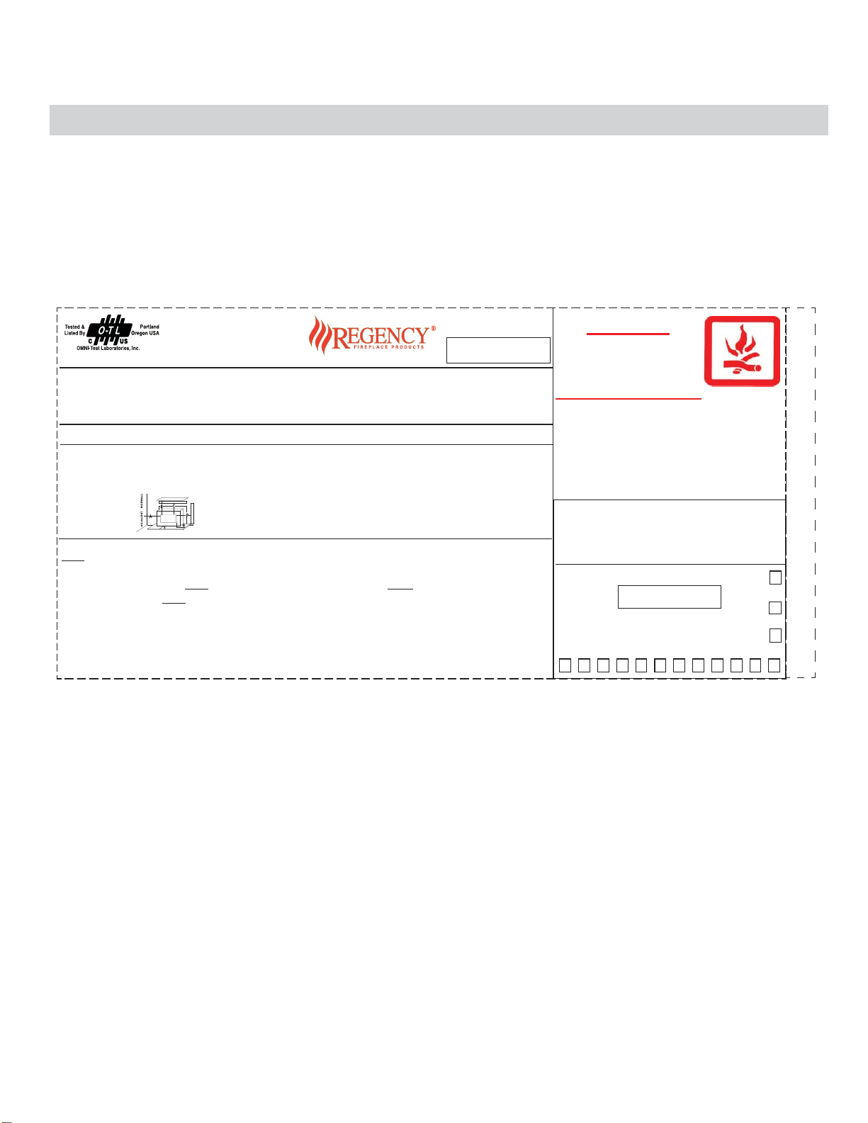
SAFETY LABEL FOR CI2600/HI400
This is a copy of the label that accompanies
your Regency Insert. We have printed a copy
of the contents here for your review.
NOTE: Regency units are constantly being
improved. Check the label on the unit and if
there is a difference, the label on the unit is the
correct one.
CI2600/HI400 | wood insert
Page 5
| 5
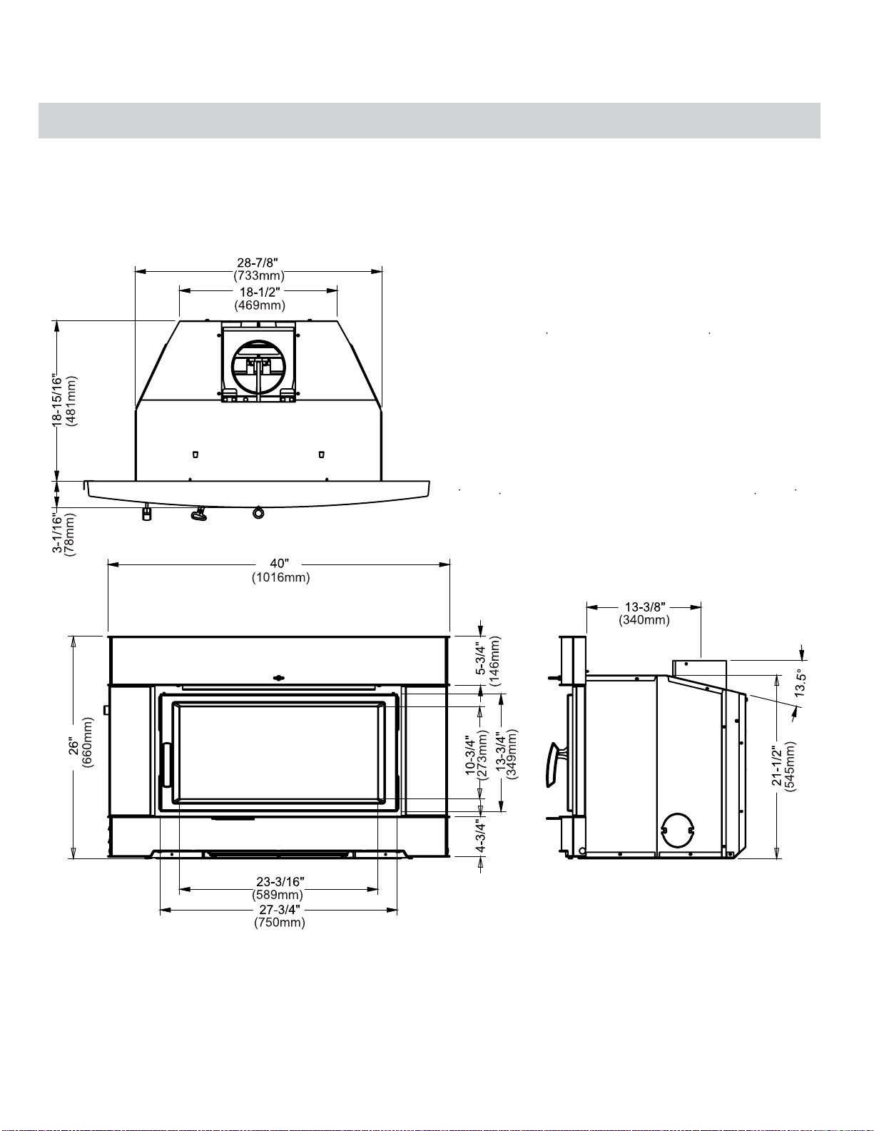
DIMENSIONS - CONTEMPORARY FACEPLATE
dimensions
CI2600/HI400 | wood insert
Page 6
6 |
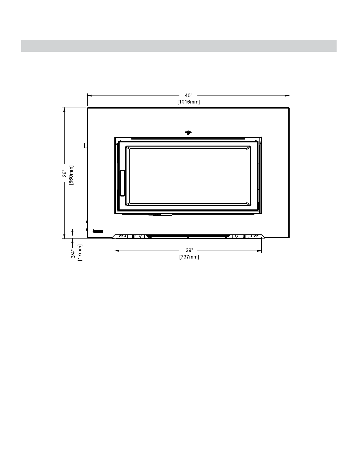
DIMENSIONS - LOW PROFILE FACEPLATE
dimensions
CI2600/HI400 | wood insert
Page 7
| 7
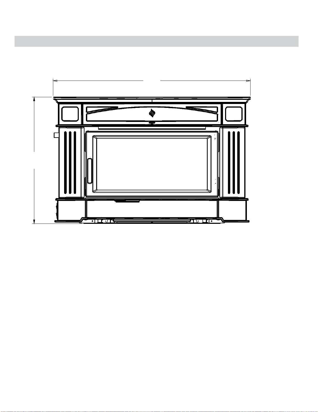
DIMENSIONS - CAST FACEPLATE
26-1/2"
673mm
dimensions
41-3/8"
1051mm
CI2600/HI400 | wood insert
Page 8

8 |
installation
Regency Inserts are constructed with the highest
quality materials and assembled under strict quality
control procedures that insure years of trouble free
and reliable performance.
It is important that you read this manual thoroughly
and fully understand the safe installation and operating procedures. The more you understand the way
your Regency Insert operates, the more enjoyment
you will experience from knowing that your unit is
operating at peak performance.
BEFORE INSTALLING YOUR
INSERT
1. Please read this entire manual before you install
and use your new wood insert. Failure to follow
instructions may result in property damage,
bodily injury or even death. Install and use only
in accordance with manufacturer’s installation
and operating instructions.
2. Check your local building codes - Building
Inspection Department. You may require a
permit before installing your insert. Be aware
that local codes and regulations may override
some items in the manual.
WARNING: Careless installation is the ma-
jor cause of safety hazard. Check all local
building and safety codes before installation
of unit.
CAUTION: Do not conduct any makeshift
compromises during installation. Warranty
will be voided.
WHEN THIS ROOM HEATER IS NOT PROP-
ERLY INSTALLED, A HOUSE FIRE MAY
RESULT. TO REDUCE THE RISK OF FIRE,
FOLLOW THE INSTALLATION INSTRUCTIONS, CONTACT LOCAL BUILDING OR
FIRE OFFICIALS ABOUT RESTRICTIONS
AND INSTALLATION INSPECTION REQUIREMENTS IN YOUR AREA.
3. Notify your home insurance company that you
plan to install a fi replace insert or hearth heater.
4. Your fi replace insert is heavy and requires two
or more people to move it safely. The insert
can be badly damaged by mishandling.
5. If your existing fi replace damper control will
become inaccessible once you have installed
your Regency Insert, you should either remove
or secure it in the open position.
CHIMNEY SPECIFICATIONS
Before installing, check and clean your chimney
system thoroughly. If in doubt about its condition,
seek professional advice. Your Regency Insert is
designed for installation into a masonry fi replace
that is constructed in accordance with the requirements of "The Standard for Chimneys, Fireplaces,
Vents, and Solid Fuel Burning Appliance", N.F.P.A.
211, the National Building Code of Canada, or the
applicable local code requirements.
The appliance, when installed, must be electrically
grounded in accordance with local codes or, in the
absence of local codes, with the National Electrical
Code, ANSI/NFPA 70, or the Canadian Electrical
code, CSA C22.1.
Regency Inserts are designed to use 6" (152mm) fl ue.
This fi replace insert must be installed with a continuous chimney liner of 6" diameter extending from the
fi replace insert to the top of the chimney. The chimney
liner must conform to the Class 3 requirements of
CAN/ULC-S635, Standard for Lining Systems for
Existing Masonry or Factory- Built Chimneys and
Vents, or CAN/ULC S640, Standard for Lining Systems
for New Masonry Chimneys,UL1777.
REQUIREMENTS FOR INSTALLING
SOLID-FUEL INSERTS IN FACTORYBUILT FIREPLACES.
1. The insert must be tested and meet the require-
ments of UL 1482 (U.S.) and or ULC S628
(Canada) when tested in a masonry fi replace.
2. The factory-built fi replace must be listed per UL
127 or ULC S610.
3. Clearances obtained from the masonry fi replace
tests are also relevant for installation in factorybuilt fi replaces.
4. Installation must include a full height listed chim-
ney liner type HT requirements (2100 degree
F.) per UL 1777 (U.S.) or ULC S635, ULCS640
(Canada). The liner must be securely attached
to the insert fl ue collar and the chimney top.
5. Means must be provided to prevent room air pas-
sage to the chimney cavity of the fi replace. This
may be accomplished by sealing the damper
area around the chimney liner, or sealing the
fi replace front.
7. Circulating air chambers (i.e. in a steel fi replace
liner or metal heat circulator) shall not be blocked.
8. Means must be provided for removal of the insert
to clean the chimney fl ue.
9. Inserts that project in front of the fi replace must
be supplied with appropriate supporting means.
10. Installer must mechanically attach the supplied
metal tag to the inside of the fi rebox of the
fi replace into which the insert is installed.
"WARNING: This fireplace has been
converted for use with a wood insert only
and cannot be used for burning wood or
solid fuels unless all original parts have been
replaced, and the fi replace re-approved by
the authority having jurisdiction."
In order for a solid-fuel insert to be certifi ed for use
in factory-built fi replaces, the above information
must be clearly stated in the installation manual and
appropriate markings. Final approval is contingent
on the authority having jurisdiction.
WOOD INSERT
SPECIFICATIONS
Your fi replace opening requires the following minimum sizes:
Height: 21-
Width: 28-13/16"
Depth: 19"
Three faceplates are available to seal the fi replace
opening:
Contemporary
Low Profi le
Cast
Emissions from burning wood or gas could contain chemicals known to the State of California
to cause cancer, birth defects or other reproductive harm.
3/4"
40" W x 26" H
40" W x 26" H
41-3/8"W x 26-1/2"H
6. Inspect your fi replace and chimney prior to
installing your insert to determine that it is free
from cracks, loose mortar or other signs of
damage. If repairs are required, they should
be completed before installing your insert. Do
not remove bricks or mortar from your masonry
fi replace.
7. DO NOT CONNECT THE INSERT TO A CHIMNEY SYSTEM SERVICING ANOTHER APPLIANCE OR AN AIR DISTRIBUTION DUCT.
8. DO NOT INSTALL IN A SLEEPING ROOM.
CI2600/HI400 | wood insert
6. Alteration of the fi replace in any manner is not
permitted with the following exceptions;
a. external trim pieces which do not affect the
operation of the fi replace may be removed
providing they can be stored on or within
the fi replace for re-assembly if the insert is
removed.
b. the chimney damper may be removed to
install the chimney liner.
Page 9
F
| 9
installation
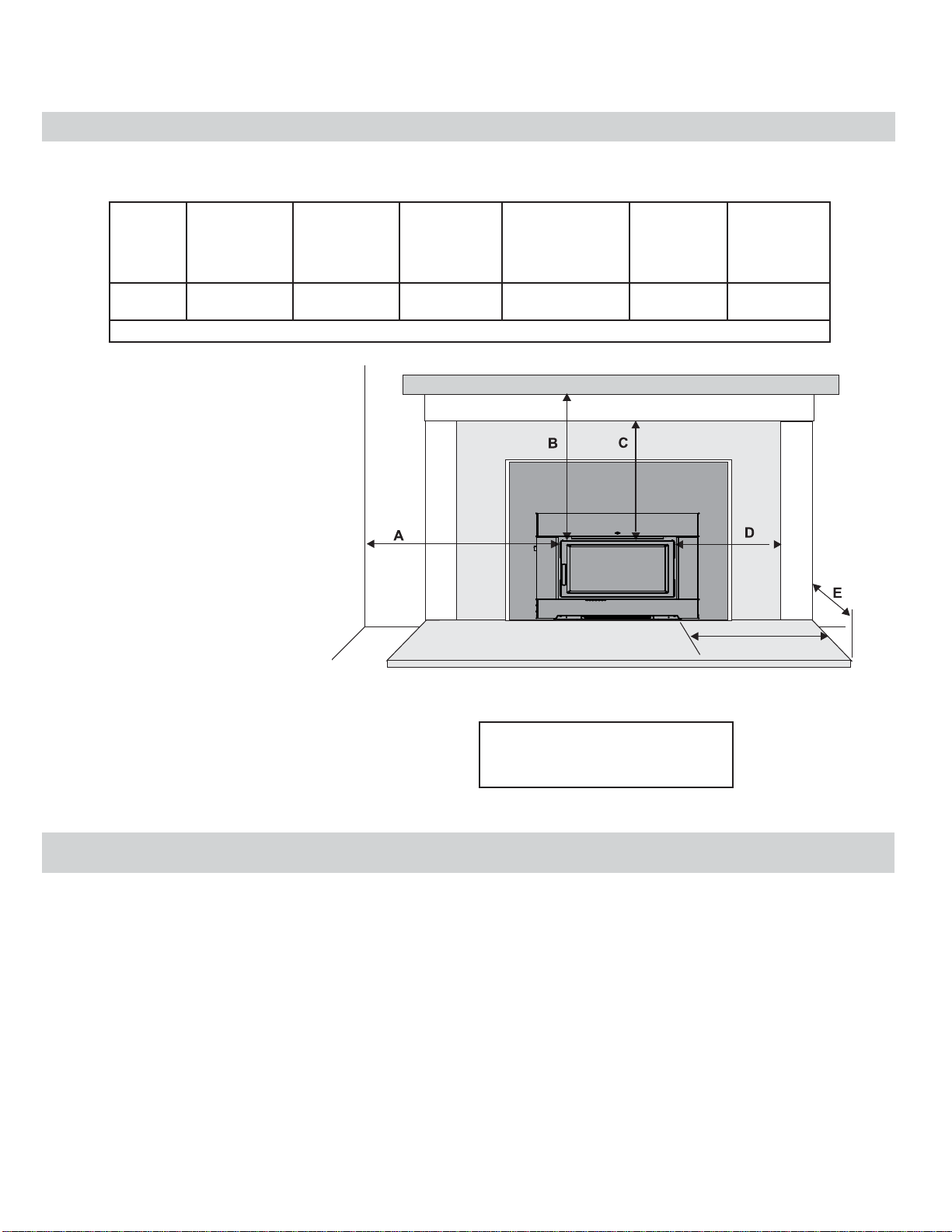
MASONRY AND FACTORY BUILT FIREPLACE CLEARANCES
The minimum required clearances to combustible materials when installed into a masonry or factory built fi replace are listed below.
Unit
CI2600/
HI400
Measurements A,B,C,D are from Top/Side of Door
Side and Top facing is a maximum of 1.5" thick.
* Side hearth extension for Canada measured
from side of appliance.
* Hearth to have minimum:
R value of 2.13 or greater.
** A non-combustible mantel may be installed
at a lower height if the framing is made of
metal studs covered with a non-combustible
board.
** Max. mantle depth is 10" (254mm).
Thermal fl oor protection is not required if the unit is
raised 6.5" minimum (measured from the bottom of
the stove). However, standard ember fl oor protection is required. It will need to be a non-combustible
material that covers 16" (406 mm) in the US and
18" (450 mm) in Canada to the front of the unit and
8" (200 mm) to the sides.
Adjacent
Side Wall
(to Side
of Door)
A
12-3/16" 21-5/8" 14" 7-3/8" US 16"
Mantle **
(to Top of Door)
B
Top
Facing
(to Top of Door
C
Side
Facing
(to Side of Door)
D
Minimum
Hearth
Extension*
E
Canada 18"
Minimum
Hearth Side
Extension*
F
8"
All fl oor protection must be non-combustible (i.e.,
metals, brick, stone, mineral fi ber boards, etc.) Any
organic materials (i.e. plastics, wood paper products,
etc.) are combustible and must not be used. The fl oor
protection specifi ed includes some form of thermal
designation similar to R-value (thermal resistance)
or k-factor (thermal conductivity).
Floor protector listed to UL1618.
Clearance diagram for Installations
Minimum Hearth Extension for the front
(E) and sides (F) are measured from the
fuel door opening.
HOW TO DETERMINE IF ALTERNATE FLOOR PROTECTION MATERIALS ARE ACCEPTABLE
The specifi ed fl oor protector should be 3/8"
(18mm) thick material with a K - factor of 0.84.
The proposed alternative is 4" (100mm) brick
with a C-factor of 1.25 over 1/8" (3mm) mineral
board with a K-factor of 0.29.
Step (a):
Use formula above to convert specifi cation
to R-value.
R = 1/k x T = 1/0.84 x .75 = 0.893.
Step (b):
Calculate R of proposed system.
4" brick of C = 1.25, therefore
Rbrick = 1/C = 1/1.25 = 0.80
1/8" mineral board of k = 0.29, therefore
Rmin.bd. = 1/0.29 x 0.125 = 0.431
Total R = Rbrick + Rmineral board =
0.8 + 0.431 = 1.231.
Step (c):
Compare proposed system R of 1.231 to
specifi ed R of 0.893. Since proposed system
R is greater than required, the system is
acceptable.
DEFINITIONS
Thermal Conductance:
C = Btu = W
(hr)(ft
Thermal Conductivity:
k = (Btu)(inch) = W = Btu
(hr)(ft3)(oF) (m)(K) (hr)(ft)(oF)
Thermal Resistance:
R = (ft2)(hr)(oF) = (m2)(K)
Btu W
2 )(o
F) (m2))(K)
CI2600/HI400 | wood insert
Page 10
10 |
installation
INSTALLING YOUR INSERT
Your insert is very heavy and will require two or three people to move it into position. The insert can be made lighter by removing the cast iron
door by opening it and lifting it off its hinges. Be sure to protect your hearth extension with a heavy blanket or carpet scrap during the installation.
Evaluate your minimum cavity opening. If the cavity height lends itself to conduct the install without removing the fl ue collar, then just slide the unit into place
and position the liner within the fl ue collar and secure.
If the cavity dictates the fl ue collar needs to be removed or the optional offset fl ue adaptor is required, please follow the steps below.
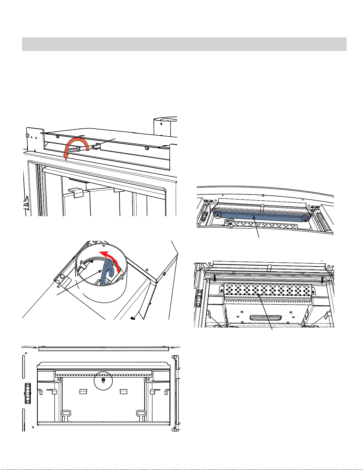
1. Remove door, manual package, and bricks - see instructions in manual.
2. Remove Bypass Rod - turn counter clockwise.
Bypass Rod
5. Install chimney liner, attach connector from fl ex kit with band and screws
(ensure tabs on connector are positioned so they won't get in the way
of the Bypass Rod - or remove them) attach fl ue collar with 2 or more
screws, to the liner within fi replace cavity.
Ensure to position at the proper height and angle to be able to attach the
unit.
6. Before sliding the unit into place and attaching the collar - the following
parts must be removed to allow access and a positive connection.
a) Primary Air Shield
b) Combustor Flame Shield
c) Combustor
d) Upper Shield - accessed through combustor opening
3. The Bypass Rod was threaded through a "Fork" - access Fork through
the fl ue and remove by bringing it through the front of the unit.
Remove Fork
4. From inside the fi rebox - remove 7/16" bolt at back of fi rebox to remove
the fl ue collar.
A -Primary Air Shield - loosen 2 x 7/16"
bolts - slide forward to remove.
B- Combustor Flame Shield - loosen 2 x 7/16"
bolts to remove.
CI2600/HI400 | wood insert
Page 11
| 11
installation
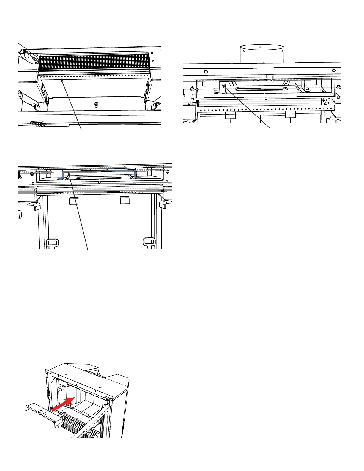
C - Combustor- remove with pliers
Tilt down and forward to ease removal.
D - Upper Shield - slide forward and lift up to remove.
7. Slide unit into position- ensure to centre with fl ue collar.
8. From inside the unit - grab the collar by accessing through the bypass
opening.
Pull the collar down and forward - use hook tool (provided with the unit)
to assist removal.
Secure with 7/16" bolt (removed in Step 4) while pulling collar down - to
ensure positive connection.
Ensure bolts is tightly secured and centred.
Upper Shield - center between 2 vertical pins
10. Reinstall "Fork" (removed in Step 4) on the bypass plate. Ensure the 5º
angled top portion of the Fork is facing towards the front of the unit.
Access through the combustor opening from inside the fi rebox to reinstall. Bypass plate may need centering before proceeding to next step.
11. Reinstall bypass rod through fl ue collar and into "Fork". Ensure bypass
rod is screwed in tightly. Test Bypass Rod to ensure positive connection
and review bypass opening.
12. Reinstall Combustor/Flame Combustor Shield / Primary Air Shield /Liner
Shield.
13. Reinstall Brick Liners and Door - (see detailed instructions in manual).
14. Center unit and install Faceplate (see instructions in manual).
15. Install Ring onto bypass rod.
9. Reinstall the Upper Shield removed in Step 6e.
Ensure Upper Shield is centered in between 2 (two) vertical pins from
front to back.
When positioning the upper shield locate the vertical pins by feel.
When the shield parts are in place - slide to the back.
E - Upper Shield - orientation for reinstall
CI2600/HI400 | wood insert
Page 12
12 |
installation
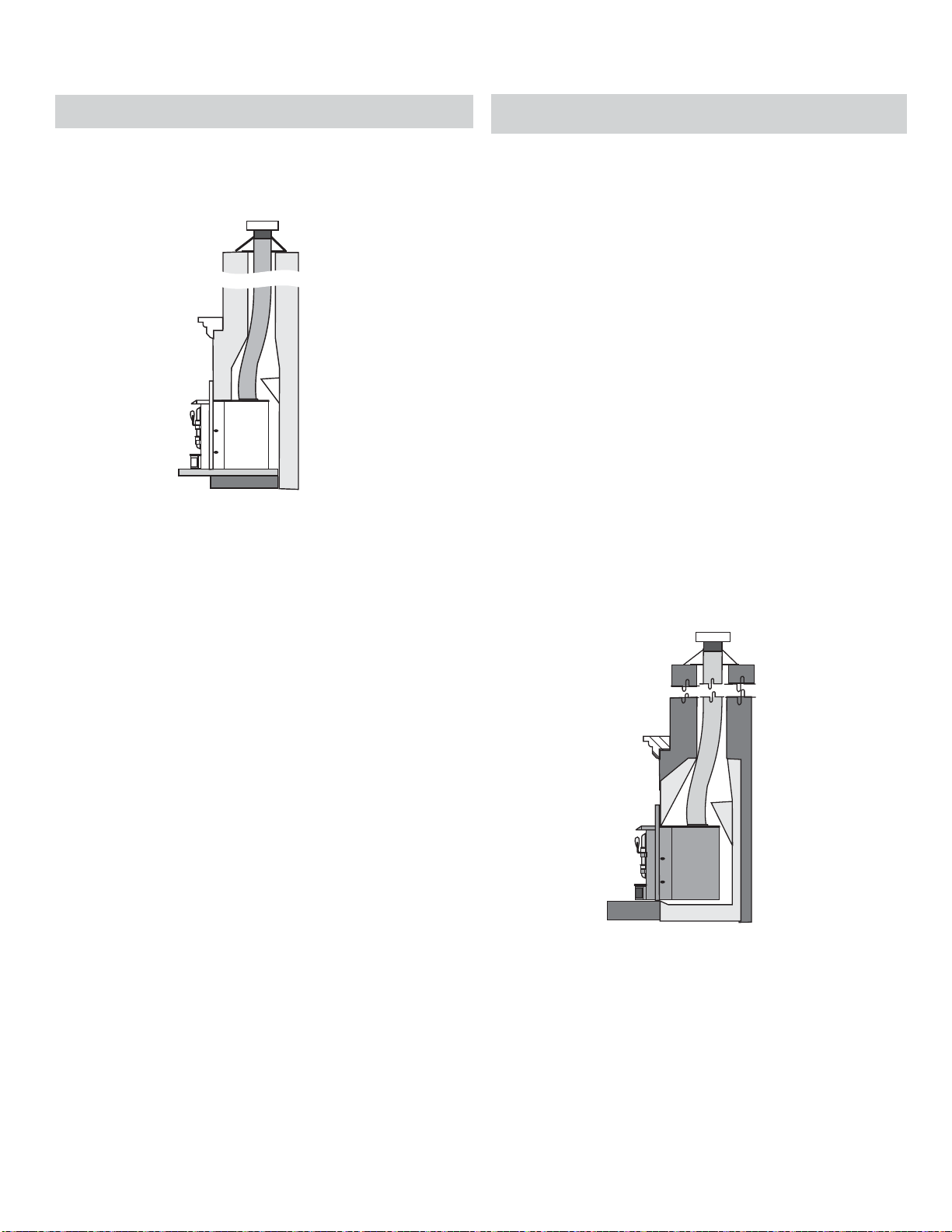
INSTALLATION INTO A MASONRY FIREPLACE
The insert must be installed as per the requirements of your local inspection
authority. A full fl ue liner is required in Canada and the US with this ap-
pliance as it has a catalytic combustor.
1) Positive Flue
Connection
with Cleanout
The installation of a full liner not only increases the safety of your insert by
directing the hot gases up the fl ue, but will also help increase the unit's effi ciency and decrease creosote deposits in the chimney.
STEP-BY-STEP INSTALLATION INTO A
FACTORY BUILT FIREPLACE
1. When installed in a factory built fi replace, a full stainless steel rigid or
fl exible fl ue liner is mandatory, for both safety and performance purposes.
When a fl ue or liner is in use, the insert is able to breathe better by allowing
a greater draft to be created. The greater draft can decrease problems
such as, diffi cult start-ups, smoking out the door, and dirty glass.
2. In order to position the fl ue liner, the existing rain cap must be removed
from your chimney system. In most cases the fl ue damper should also
be removed to allow passage of the liner.
3. In most cases opening the existing spark screens fully should give enough
room for the insert installation. If it does not, remove and store.
4. If the fl oor of your fi replace is below the level of the fi replace opening,
adjust the insert's levelling bolts to accommodate the difference. When
additional shimming is required, use non-combustible masonry or steel
shims.
5. Measure approximately the alignment of the fl ue liner with the position of
the smoke outlet hole on the insert to check for possible offset. If an offset
is required, use a proper stainless steel unit available with the chimney
liner.
6. Once the above items have been checked, slide your insert into position
after fi rst positioning the fl ue liner and offset if required. (Re-install raincap
at completion of installation).
NOTE: Refer to "Requirements for Installing Solid-fuel Inserts in Factory-
built Fireplaces" section for the requirements for installing solid
fuel inserts in factory built fi replaces.
When a connected fl ue or liner is in use, the inser t is able to “breathe” better by
allowing a greater draft to be created. The greater draft can decrease problems
such as, diffi cult start-ups, smoking out the door, blocked catalyst,unburned
wood, and dirty glass.
Flush Inserts
CI2600/HI400 | wood insert
Page 13

| 13
OPTIONAL CAST GRILL INSTALLATION
GLASS REMOVAL TO INSTALL
OPTIONAL DOOR CAST GRILL
1. To remove the glass, loosen the two 7/16" bottom retainer bolts
but do not remove.
2. Remove the sides and top retainer and bolts highlighted in the
diagram and carefully remove glass, it will fall towards you at the top.
3. Place the grill in the door, make sure that the glass gasketing on the
left and right bracket is facing you.
4. Carefully place the glass (black strip up) into the bottom retainer.
Keeping it in place, re-install the sides and top retainer and bolts.
Do not tighten bolts, fi nger tight only.
5. Lift the bottom of the glass upwards till it stops, secure glass retainer
using the 8 bolts. Do not wrench down on the bolts, as this may cause
the glass to break.
installation
Remove 6 - 7/16" Bolts
Avoid impact on glass doors such
as striking or slamming shut.
FIREBRICK ASSEMBLY
Firebrick is included to extend the life of your insert and radiate heat more evenly. Check to see that all
fi rebricks are in their correct positions and have not become misaligned during shipping.
CI2600/HI400 | wood insert
Page 14

14 |
installation
OPTIONAL BACKING PLATE INSTALLATION
An optional backing plate is available in either a standard or custom
size.
1. The backing plate is packaged in three pieces and requires assem-
bly. The legs of the backing plate are attached to the top plate with
2 screws on each side. See diagram 1 below.
Top plate
Leg
Diagram 1
3. Slide assembled backing plate over unit. Line up fl ange on backing
plate with fl ange on unit and secure with 2 screws from the underside
as shown below.
Proceed with Faceplate install.
Backer Plate
Screws
Diagram 3
2. The pointed end of the screws should be facing the front of the back-
ing plate.
Diagram 2
Flush front face of
backing plate
Diagram 4
Completed backing plate shown with Optional Hampton faceplate
CI2600/HI400 | wood insert
Page 15

p
| 15
CONTEMPORARY FACEPLATE INSTALLATION
installation
Remove unit door prior to installation of faceplate.
Remove all contents from the package and lay out.
NOTE: Bolts may be pre-installed on unit and will need to be removed
prior to each step of the noted instructions. As a result, there may be
spare bolts.
1. Install tool and handle holder to the left side of the unit with on - 7/16"
bolt as shown below. (Note: part is packed with the manual package).
Handle / Tool holder
2. Install the upper left and right brackets using the four 7/16" bolts.
4. Attach the left and right side rails to the back of the bottom fascia panel
using four 7/16’’ bolts.
NOTE: Wheels should be facing outward when completed.
Rail system secured with 4 bolts
NOTE: Fan cassette must be installed prior to this step. See fan install
instructions.
5. Remove the ring on the bypass rod by turning counter clockwise and
pull bypass rod forward to the open position. Then take the top fascia
panel and gently slide the bypass rod through the hole in the fascia
panel. Lift the fascia panel up slightly - push back to engage the brackets installed on step 1.
Brackets with Bolts
3. Install the left and right of the fascia panels using four 7/16’’ bolts.
Fascia side
anels installed with Bolts
CI2600/HI400 | wood insert
Remove Ring from Bypass Rod
Back view of Top Fascia Panel lining up with the
brackets installed in Step 1
Page 16

16 |
installation
6. Take the bottom fascia and line up the wheels and rails with the rails on
the unit. Once lined up lift up and into the rail system and slide into position.
Rail System
7. Re-install bypass ring and door.
Final Install
CI2600/HI400 | wood insert
Page 17

| 17
LOW PROFILE FACEPLATE INSTALLATION
installation
Remove unit door prior to installation of faceplate.
Remove all contents from the package and lay out.
NOTE: Bolts may be pre-installed on unit and will need to be removed
prior to each step of the noted instructions. As a result, there may be
spare bolts.
1. Install tool and handle holder to the left side of the unit with on - 7/16"
bolt as shown below. (Note: part is packed with the manual package).
Handle / Tool holder
2. Install the upper left and right brackets using the four 7/16" bolts.
Identify proper orientation below before installing.
NOTE: If installing blower, optional Fan cassette must be installed prior at
this point. See fan installation instructions for details.
If not installing blower—proceed to Step 6.
4. Remove dummy plate from left side of faceplate by removing 2 screws.
Set screws aside, use to secure the fan switch assembly in Step 5.
Brackets with Bolts
Left Bracket Right Bracket
3. Remove the ring on the bypass rod by turning counter clockwise - pull
bypass rod forward to the open position.
Dummy Plate
5. With fan cassette in position—take the fan switch assembly (attached
to the fan cassette wiring harness) and install into opening created by
dummy plate removal. Ensure fan switch assembly is fully seated onto
faceplate and secure with 2 screws from Step 4.
Install fan switch assembly
Remove ring from the
bypass rod
CI2600/HI400 | wood insert
Page 18

18 |
installation
6. Gently slide the bypass rod through the center hole within the fascia and
also guide the primary air control through the slot in the bottom of the
fascia. Push the faceplate towards the unit, ensuring the bolts in Step 2
slide into the brackets installed in Step 1.
Final Install
7. Ensure the left and right side bolts on the top of the Low Profi le Face-
plate are spaced evenly. The spacing of these bolts is critical to ensure
the faceplate slides into the brackets installed in Step 1.
7/16" bolts on back of
Faceplate
8. Tighten the 7/16’’ bolts on the back of the Flat Faceplate
9. Re-install bypass ring and door.
CI2600/HI400 | wood insert
Page 19

| 19
CAST FACEPLATE INSTALLATION
installation
Remove unit door prior to installation of faceplate.
Remove all contents from the package and lay out.
1. Install tool and handle holder to the left side of the unit with on - 7/16"
bolt as shown below. (Note: part is packed with the manual package).
Handle / Tool holder
2. Install the upper left and right brackets using the four 7/16" bolts.
4. Install the left and right of the fascia panels using four 7/16’’ bolts.
Fascia side panels installed with Bolts
NOTE: Fan cassette must be installed prior to this step. See fan install
instructions.
5. Attach the left and right side rails to the back of the bottom fascia panel
using four 7/16’’ bolts.
Brackets with Bolts
3. Install two brackets to the back of each side panel with four 7/16’’ bolts.
CI2600/HI400 | wood insert
Rail system secured w/bolts
Page 20

20 |
6. Take the bottom fascia and line up the wheels and rails with the rails on
installation
the unit. Once lined up lift up and into the rail system and slide into position.
Rail System
8. Re-install bypass ring and door.
7. Remove the ring on the bypass rod by turning counter clockwise and
pull bypass rod forward to the open position. Then take the top fascia
panel and gently slide the bypass rod through the hole in the fascia
panel. Lift the fascia panel up slightly - push back to engage the brackets installed on step 1.
Completed Optional Hampton Cast Faceplate
Note: If installing optional cast grill - follow installation instructions in this
manual.
Back view of Top Fascia Panel lining up with the
brackets installed in Step 1
CI2600/HI400 | wood insert
Page 21

| 21
installation
OPTIONAL FAN/BLOWER INSTALLATION
Installer: Please record unit serial number here before installing blower—serial number will not be visible after blower
is installed.
Serial No.
The fan should only be installed once the unit is in
place in order to prevent any damage to the fan.
1. Remove 2- 5/16" screws from locations
shown below—set aside for installation.
Remove 2 screws from locations shown
2. Slide the fan cassette fully into position.
______________________________
4. Secure using the two (2) 5/16" screws re-
moved from Step 1.
Secure fan with 2 screws removed in Step 1
5. Remove 7/16" bolts from position shown
below.
**See specifi c faceplate installation instructions
for detailed instructions of fan switch assembly.
6. Align preset strain relief bracket to bottom
right corner of the faceplate, secure with 7/16"
bolt removed in Step 5.
8. Tuck Power Cord to the bottom right hand side
of the faceplate as shown.
Tuck cord to right side of faceplate
Do not turn fan ON until your insert has reached
operating temperature or at least 30 minutes
after starting fi re.
Line up fan cassette with screw holes.
3. Align screw holes on fan harness bracket
with holes in fan cassette mounting bracket
on right and left sides.
CI2600/HI400 | wood insert
Secure preset strain relief
7. Remove the dummy plug from the faceplate
being installed, by removing the 2 screws along
with washers and nuts. Discard dummy plug,
but keep hardware. Install fan switch assembly with 2 screws, washers and nuts to lower
fascia before sliding faceplate into position.
Fan switch assembly
Page 22

22 |
installation
Neutral
120V AC
60 Hz
Live
Fan Thermodisc
(normally open)
Ground
Green
Black Black
Black
Blower/Fan Wiring Diagram
CAUTION: Label all wires prior
to disconnection when servicing
controls. Wiring errors can cause
improper and dangerous operation.
Manual/
Auto
Switch
Fan
Switch
Low (Red)
High (Black)
Fan Fan
White
Ground
WARNING:
Electrical Grounding
Instructions
This appliance is equipped with
a three pronged (grounding) plug
for your protection against shock
hazard and should be plugged
directly into a properly grounded
three-prong receptacle. Do not
cut or remove the grounding
prong from this plug.
CI2600/HI400 | wood insert
Page 23

| 23
installation
REMOVABLE DOOR HANDLE
The CI2600/HI400 has a removable door handle that can be stored when not in use. All the faceplates have a storage hook on the left side that accommodates the handle.
Hook
Handle
The cool to touch door handle is designed to be inserted from the bottom up and slide off when not held in place. Once in position, the door
can be opened. After use, store the door handle on the storage hook
located on the left side of the faceplate
WARNING: FAILURE TO USE REMOVABLE HANDLE AS PER INSTRUCTIONS MAY CAUSE SERIOUS BURNS.
BYPASS HANDLE
The CI2600/HI400 is supplied with a bypass operating handle.
The handle is used to open or close the bypass when re-loading
Bypass Handle
CI2600/HI400 | wood insert
Page 24

24 |
operating instructions
OPERATING INSTRUCTIONS
With your unit now correctly installed and safety
inspected by your local authority, you are now ready
to start a fi re. Before establishing your fi rst fi re, it
is important that you fully understand the operation of your Catalytic combustor and draft control.
WARNING
Fireplace Inserts equipped with doors
should be operated only with doors
fully closed. If doors are left partly open,
gas and fl ame may be drawn out of the
fi replace stove opening, creating risks
from both fi re and smoke.
DRAFT CONTROL
Both the primary and air wash drafts are controlled
by the control slide located on the front left side
of the unit (when facing the unit). To increase your
draft - slide to the left to open, and to decrease slide to the right closed. The CI2600/HI400 unit has
a secondary draft system that continually allows
combustion air to the induction ports at the top of
the fi rebox, just in front of the catalytic combustor.
Draft is the force which moves air from the appliance up through the chimney. The amount of draft
in your chimney depends on the length of the
chimney, local geography, nearby obstructions and
other factors. Too much draft may cause excessive
temperatures in the appliance and may damage the
catalytic combustor. Inadequate draft may cause
back puffi ng into the room and plugging of the
chimney or catalyst.
In - Closed Out - Open
Catalyst Bypass Control
Primary Air Damper
Left - Open Right - Closed
WARNING: To build a fi re in ignorance
or to disregard the information contained in this section can cause serious
permanent damage to the unit and void
your warranty!!
CI2600/HI400 | wood insert
FIRST FIRE
When your installation is completed and inspected
you are ready for your fi rst fi re.
THIS UNIT IS DESIGNED TO BURN SEASONED
CORDWOOD ONLY. COAL AND BRIQUETTES
ARE NOT APPROVED.
1. Open the catalytic by-pass control fully.
(Handle pulled out) and open primary air
damper to the full open position
2. The unit is equipped with log andirons to aid
in keeping fuel from sliding, rolling towards the
glass. Please ensure all fuel is loaded behind
the andirons.
Open fi rebox door and build a small fi re using
paper and dry kindling on the fi rebrick hearth,
DO NOT USE A GRATE Secure door on the
fi rebox and wait a few minutes for a good updraft in the fl ue to establish the fi re. (Leaving
the door slightly open will help your fi re start
more rapidly.)
CAUTION: Never leave unit unattended
if door is left open. This procedure
is for fi re start-up only, as unit may
overheat if door is left open for too
long.
3. With the catalytic by-pass damper still in the
fully open position, add two or three seasoned
logs to your fi re. Form a trench in the ash bed
to allow air to reach the rear of the fi rebox prior
to closing the door.
4. The temperature in the stove and the gases
entering the combustor must reach between
5000F - 7000F for catalytic activity to start. From
the start up of a cold stove, a medium to high
fi ring rate must be maintained for 30 min. This
ensures that the stove, catalyst and fuel are all
stabilized at proper operating temperatures.
Even though it is possible to have temperatures at 6000F within minutes after a fi re has
been started, if the fi re is allowed to die down
immediately it may go out or the combustor
may stop working. Once the combustor starts
working, heat generated in it by burning the
smoke will keep it working. During re-fueling
and rekindling of the cool fi re, or a fi re that has
burned down to the charcoal phase, operate
the stove at a medium to high fi ring rate for
about 10 minutes to ensure that the catalyst
reaches operating temperatures
WARNING: Never build a roaring fi re
in a cold stove. Always warm your
stove up slowly!
5. When re-fueling, always open by-pass control,
load fuel, then wait for at least 10-15 minutes
before closing the by-pass. Reason for the
10-15 min. is the fresh fuel and the opening
of the door will cause the catalyst to drop in
temperature as well as the moisture within the
wood which is the fi rst thing to be released.
6. During the fi rst few fi res, keep the combustion
rate at a moderate level and avoid a large fi re.
Only after 5 or 6 such fi res can you operate the
stove at its maximum setting, and only after the
metal has been warmed.
7. For the fi rst few days, the stove will give off an
odour from the paint. This is to be expected as
the high temperature paint becomes seasoned.
Windows and/or doors should be left open to
provide adequate ventilation while this temporary condition exists. Burning the stove at a
very high temperature the fi rst few times may
damage the paint. Burn fi res at a moderate level
the fi rst few days.
8. Do not place anything on the stove top during
the curing process. This may result in damage
to your paint fi nish.
9. During the fi rst few days it may be more diffi cult
to start the fi re. As you dry out your fi rebrick and
your masonry fl ue, your draft will increase.
10. For those units installed at higher elevations or
into sub-standard masonry fi replaces, drafting
problems may occur. Consult an experienced
dealer or mason on methods of increasing your
draft.
11. Some cracking and popping noises may be
experienced during the heating up process.
These noises will be minimal when your unit
reaches temperature.
12. Before opening your door to reload, open the
by-pass damper fully for approximately 10 to 15
seconds until the fi re has been re-established.
This will minimize any smoking (spilling) back
into the room. After loading wood and front door
closed, close the by-pass damper
13. All fuel burning appliances consume oxygen
during operation. It is important that you
supply a source of fresh air to your unit while
burning. A slightly opened window is suffi cient
for the purpose. If you also have a fi replace
in your home, a downdraft may be created by
your Regency Stove causing a draft down your
chimney. If this occurs, slightly open a window
near your unit.
CAUT ION: If the body of your unit, or any part
of the chimney connector starts to glow, you
are over fi ring. Stop loading fuel immediately
and close the draft control until the glow has
completely subsided.
14. Green or wet wood is not recommended for
your unit. If you must add wet or green fuel,
open the draft control fully until all moisture has
been dispersed by the intense fi re. Once all
moisture has been removed, the draft control
may be adjusted to maintain the fi re.
15. If you have been burning your stove on a low
draft, use caution when opening the door. After
opening the damper, open the door a crack, and
allow the fi re to adjust before fully opening the
door.
16. The controls of your unit or the air supply pas-
sages should not be altered to increase fi ring
for any reason.
Page 25

| 25
operating instructions
17. If you burn the unit too slowly or at too low a set-
ting your unit will not be operating as effi ciently
as it can. An easy rule of thumb says that if
your glass is clean, catalytic thermostat is active, then your fl ue is clean and your exhaust is
clean. Burn the stove hot enough to keep your
glass clean and catalytic combustor ,you won't
need to clean your fl ue as often.
HOT WHILE IN OPERATION. KEEP
CHILDREN, CLOTHING AND
FURNITURE AWAY. CONTACT MAY
CAUSE SKIN BURNS.
ASH DISPOSAL
During constant use, ashes should be removed
every few days. Please take care to prevent the
build-up of ash around the start-up air housing
located inside the fi rebox, under the loading door lip.
DO NOT ALLOW ASHES TO BUILD UP TO THE
LOADING DOORS.
Only remove ashes when the fi re has died down.
Even then, expect to fi nd a few hot embers. Always
leave 1 to 2 inches of ash in the bottom of the fi rebox.
This helps in easier starting and a more uniform
burn of your fi re.
Ashes should be placed in a metal container with
a tight fi tting lid. The closed container of ashes
should be placed on a noncombustible fl oor or on
the ground, well away from all combustible materials,
pending fi nal disposal. If the ashes are disposed of
by burial in soil or otherwise locally dispersed, they
should be retained in the closed container until all
cinders have thoroughly cooled. Other waste should
not be placed in the ash container.
FAN OPERATION
The fan unit must not be turned on until a fi re has
been burning for at least 30 minutes and the unit
is hot enough. As well, after each fuel loading the
fan must be shut off until 30 minutes has elapsed.
To operate fan automatically, push switch on side of
fan housing to "Auto" and second switch to either
"High" or "Low" for fan speed. The automatic temperature sensor will engage the blower when the
unit is at temperature and will shut off the blower
once the fi re has gone out and the unit has cooled
to below a useful heat output range.
To manually operate the fan system, push the fi rst
switch to "Man" and second switch to either "high"
or "Low". This will bypass the sensing device and
allow full control of the fan. Switching from "Auto" to
"Manual" or "High" to "Low" may be done at any time.
To achieve maximum effi ciency and performance,
operate the fan in the low speed when the air control
is not more than ¼’’ open from its lowest setting. See
draft control instructions for operation of air control.
When the appliance is cool it is important to clean
in and around the fan. Always ensure areas on the
hearth are clean and ashes, debris etc. are not
pushed towards the bottom of the fascia. Always
brush and clean debris away from the unit, not
towards.
CREOSOTE
When wood is burned slowly, it produces tar and
other organic vapors, which form creosote when
combined with moisture. The creosote vapors
condense in the relatively cool chimney fl ue of a
slow-burning fi re. As a result, creosote residue
accumulates on the fl ue lining. When ignited,
this creosote can make an extremely hot fi re.
For wood-burning heaters, reference to the formation and removal of creosote buildup in the
chimney connector and chimney as follows (the
inspection frequency "once every two months'
stated below may be a shorter time period at
the manufacturer's or private labeler's options):
"Creosote - Formation and Need for Removal
The chimney connector and chimney should be
inspected at least once every two months during the
heating season to determine if a creosote buildup
has occurred.
If creosote has accumulated it should be removed
to reduce the risk of chimney fi re.
REMOVAL FOR CLEANING
Removal of your insert for cleaning purposes is
usually not required if a proper installation has been
done. In the event that removal is required, be sure
not to damage any parts needed for re-installation.
In most cases removal and replacement of the
baffl e system should allow full access for cleaning.
WARNING: In case of chimney fi re:
1. Close draft control
2. Call the Fire Department
WAYS TO PREVENT AND KEEP
UNIT FREE OF CREOSOTE
1. Burn insert with draft control wide open for
about 45 minutes every morning during burning
season. This helps to prevent creosote deposits
within the heating system.
2. Burn inser t with draft control wide open for about
10 - 15 minutes every time you add fresh wood.
This allows the wood to achieve the charcoal
stage faster and burns up any wood vapors
which might otherwise be deposited within the
system.
3. Only burn seasoned wood! Do not burn wet
or green wood. Seasoned wood that has been
dried at least one year must be used.
4. A small hot fi re is preferable to a large smoul-
dering one that can deposit creosote within the
system.
5. Check the chimney at least twice a month during
the burning season for creosote build-up.
6. Have chimney system and unit cleaned by
competent chimney sweeps twice a year
during the fi rst year of use and at least once
a year thereafter or when a signifi cant layer
of creosote has accumulated (3mm / 1/8" or
more) it should be removed to reduce the
risk of a chimney fi re.
WOOD STORAGE
Store wood under cover, such as in a shed, or covered with a tarp, plastic, tar paper, sheets of scrap
plywood etc., as uncovered wood can absorb water
from rain or snow, delaying the seasoning process.
SAFETY GUIDELINES & WARNINGS
DO NOT USE CHEMICALS FOR
CAUTION
1. Never use gasoline, gasoline type lantern fu-
2. Keep the door closed during operation and
3. Do not burn any quantities of paper, garbage, and
4. If you have smoke detectors, prevent smoke
5. Do not overfi re heater. If the chimney connector,
6. Do not permit creosote or soot build-up in the
7. Your Regency stove can be very hot. You may be
8. The stove consumes air while operating, provide
FLUIDS TO START FIRE.
els, kerosene, charcoal lighter fuel, or similar
liquids to start or ‘freshen up’ a fi re in your
heater. Keep all such liquids well away from
the heater while it is in use.
maintain all seals in good condition.
never burn fl ammable fl uids such as gasoline,
naptha or engine oil in your stove.
spillage as this may set off a false alarm.
fl ue baffl e or the stove top begin to glow, you are
over fi ring. Stop adding fuel and close the draft
control. Over fi ring can cause extensive damage
to your stove including warping and premature
steel corrosion. Over fi r ing will void your warranty.
chimney system. Check and clean chimney at
regular intervals. Failure to do so can result in a
serious chimney fi re.
seriously burned if you touch the stove while it is
operating, keep children, clothing and furniture
away. Warn children of the burn hazard.
adequate ventilation with an air duct or open a
window while the stove is in use.
CI2600/HI400 | wood insert
Page 26

26 |
operating instructions
SAFETY GUIDELINES & WARNINGS
9. Do not connect this unit to a chimney fl ue serving another appliance.
10. Do not use grates, andirons or other methods for supporting fuel. Burn
directly on the bricks.
11. Open the draft control fully for 10 to 15 seconds prior to slowly opening the
door when refuelling the fi re.
12. Do not connect your unit to any air distribution duct.
13. This heater is designed to burn natural wood only. Higher effi ciencies and
lower emissions generally result when burning air dried seasoned hardwoods, as compared to softwoods or to green or freshly cut hardwoods.
14. Do not store any fuel closer than 2 feet from your unit. Do not place wood,
paper, furniture, drapes or other combustibles near the appliance.
DO NOT BURN:
• Treated wood
• Coal
• Garbage
• Cardboard
• Solvents
• Colored Paper
• Trash
• Salt drift wood
• Cut lumber, plywood, mill ends.
Burning treated wood, garbage, solvents, colored paper or trash may result
in release of toxic fumes and may poison or render ineffective the catalytic
combustor. Burning coal, cardboard, or loose paper can produce soot, or
large fl akes of char or fl y ash that can coat the combustor, causing smoke
spillage into the room, and rendering the combustor ineffective.
15. Do not operate with broken glazing.
16. The controls of your unit or the air supply passages should not be altered
to increase fi ring for any reason.
17. If you burn the unit too slowly or at too low a setting your unit will not be
operating as effi ciently as it can. An easy rule of thumb says that if your
glass is clean, catalytic thermostat is active, then your fl ue is clean and
your exhaust is clean. Burn the stove hot enough to keep your glass clean
and catalytic combustor ,you won't need to clean your fl ue as often.
DO NOT BURN GARBAGE OR FLAMMABLE LIQUIDS SUCH
AS GASOLINE, NAPTHA OR ENGINE OIL. SOME FUELS
COULD GENERATE CARBON MONOXIDE AND ARE
CAUTION: DO NOT CONNECT TO, OR USE IN CONJUNC-
TION WITH ANY AIR DISTRIBUTION DUCT WORK UN-
LESS SPECIFICALLY APPROVED FOR SUCH
Troubleshooting Guide
PROBLEM POSSIBLE CAUSE SOLUTION
Crumbling Substrate Extreme Thermal Shock
Fly-Ash Build-up
Fly-Ash Masking
Fly-ash Plugging
Thermal Cracking Uneven temperatures, fl ame impingement
Mechanical Cracks Combustor mishandled or abused.
Plugging (Creosote) Burning wet, pitchy woods or burning large
Masking (Soot) Combustor has not maintained a light-off.
Refueling with Wet Wood
High Draft
Combustor has not maintained light-off
temperature.
Combustor has not maintained light-off
temperature.
Burning materials that produce a lot of char
and fl y-ash.
Closing the bypass too soon
and heat spikes.
Distortion of combustor holder.
loads of small diameter wood with the
combustor in the operating position without
light-off ever occurring.
Burning coal will cause a sulfur-based
compound to coat the catalyst.
Bypass combustor when the stove is running
Use seasoned, dried wood.
Do not exceed .06" of water draft. Install a manual damper
and draft gauge or a barometric damper.
Brush cold combustor with a soft bristled brush or vacuum
lightly.
Brush cold combustor with a soft bristled brush or vacuum
lightly.
Do not burn cardboard, gift wrap or garbage.
Follow instructions for proper light-off.
If cracking causes large pieces to fall out, replace combustor.
Handle combustor with care. Replace if necessary.
Replace combustor is large pieces are missing, replace any
warped stove parts as well.
Burn dried seasoned wood. Make sure combustor has lightoff before closing the bypass damper. It may be possible to
burn off the soot or creosote accumulation by putting the
combustor in a partially open and partially closed position
after a hot fi re has been started.
Place combustor in a partially open and partially position after
a hot fi re has been started to burn off the soot accumulation.
Revert to burning wood and fi re the combustor to elevated
temperatures for one hour.
VERY DANGEROUS.
INSTALLATION.
CI2600/HI400 | wood insert
Page 27

| 27
CATALYTIC COMBUSTOR (PART # 106-534)
operating instructions
ACHIEVING AND MAINTAINING CATALYST LIGHT-OFF:
The temperature in the stove and the gases entering the combustor must be
raised to between 500F to 700F for catalytic activity to be initiated. During the
start up of a cold stove a medium to high fi ring rate must be maintained for
about 30 minutes. This ensures that the stove, catalyst and fuel are all stabilized at proper operating temperatures. Even though it is possible to have
temperatures at 600F within minutes after a fi re has been started, if the fi re
is allowed to die down immediately it may go out or the combustor may stop
working. Once the combustor starts working, heat generated in it by burning
the smoke will keep it working. During re-fueling and rekindling of the cool
fi re, or a fi re that has burned down to the charcoal phase, operate the stove
at a medium to high fi ring rate for about 10 minutes to ensure that he catalyst
reaches operating temperatures.
There are some obvious signs of trouble that your inspection may reveal.
The temperature in the stove and the gases entering the combustor must be
raised to between 500F to 700F for catalytic activity to be initiated. During the
start up of a cold stove a medium to high fi ring rate must be maintained for
about 30 minutes. This ensures that the stove, catalyst and fuel are all stabilized at proper operating temperatures. Even though it is possible to have
temperatures at 600F within minutes after a fi re has been started, if the fi re
is allowed to die down immediately it may go out or the combustor may stop
working. Once the combustor starts working, heat generated in it by burning
the smoke will keep it working. During re-fueling and rekindling of the cool
fi re, or a fi re that has burned down to the charcoal phase, operate the stove
at a medium to high fi ring rate for about 10 minutes to ensure that he catalyst
reaches operating temperatures.
CATALYST MONITORING: It is important to periodically monitor the operation of the catalytic combustor to ensure that it is functioning properly and to
determine when it needs to be replaced. A non-functioning combustor will
result in a loss of heating effi ciency, and an increase in creosote and emissions. Following is a list of items that should be checked on a periodic basis.
• Combustors should be visually inspected at least three times during the
heating season to determine if physical degradation has occurred. Actual
removal of the combustor is not recommended unless more detailed inspection is warranted because of decreased performance. If any of these
conditions exist, refer to Catalyst trouble shooting section of this owner’s
manual.
• A good combustor is designed to withstand approximately 12,000 hours of
continuous use. This will translate into fi ve to ten years of use, depending
on the length of your heating season and how often you use your stove.
Proper maintenance will increase the combustor’s effectiveness and prevent many problems. Inspect your combustor before each heating season,
and during the season if your stove’s performance seems to change.
Step 1: Light the stove in accordance with instructions within this
manual.
Step 2: With smoke routed through the catalyst (by-pass closed)
go outside and observe the emissions leaving the chimney.
Step 3: Engage the bypass mechanism and move to by-pass
open position. And again observe the emission leaving
the chimney. Signifi cantly more smoke should be seen
when the smoke is not routed through the combustor (bypass open). Be careful not to confuse smoke with steam.
ACHIEVING PROPER DRAFT: Draft is the force which moves air from the
appliance up through the chimney. The amount of draft in your chimney
depends on the length of the chimney, local geography, nearby obstructions
and other factors. Too much draft may cause excessive temperatures in the
appliance and may damage the catalytic combustor. Inadequate draft may
cause back puffi ng into the room and plugging of the chimney or catalyst.
CATALYTIC COMBUSTOR CLEANING:
Method #1
A vacuum cleaner may be used, but never use high pressured air to
blow the cells free of any build-up. This can damage the cell walls. Any cell
blockage can be removed with the use of a pipe cleaner or a cotton swab
as well.
Method #2
Should the combustor’s cells become covered with fl y-ash, use a paintbrush or soft-bristled brush and dust the combustor gently.
Never use anything abrasive to clean the combustor.
Method #3
Normally the catalytic combustor requires little or no maintenance, it generates such high temperatures and therefore is basically self-cleaning.
However, should the combustor become covered with soot or creosote, it
is possible to burn the accumulation off by opening the bypass and building a hot fi re.
Once the hot fi re is created, close the bypass halfway and burn for 30 to 60
minutes with the bypass left in this position. Never use cleaning solvents
to clean it.
Check and clean the combustor, if necessary, before each burning season
and inspect the fl ue system for any signs of creosote buildup.
A clean fl ue helps prevent chimney fl ue fi res.
• You can get an indication of whether the catalyst is working by compar-
ing the amount of smoke leaving the chimney when the smoke is going
through the combustor and catalyst light – off has been achieved, to the
amount of smoke leaving the chimney when the smoke is not routed (bypass open) through the combustor.
CI2600/HI400 | wood insert
Page 28

28 |
operating instructions
PROVISION FOR CATALYTIC COMBUSTOR TEMPERATURE PROBE
NOTE: 1/4" drill bit required for this installation.
The CI2600/HI400 is equipped with a provision to accept a catalytic temperature monitoring device. Please follow instructions below for the installation of
the probe. Follow the user instructions of the catalytic monitoring device for
product set up and details.
Device
Probe
1. Remove all packaging from the unit
2. Locate the precut square on the top of the unit. Lift up the metal square to
900 with a fl at head screwdriver.
3.
Locate the 7/16’’ bolt below the metal. Use a 7/16’’ socket and remove the bolt.
5. Take your temperature probe and measure from end 3’’ and make a mark.
Insert the temperature probe to the mark.
Install temperature probe
6. Complete the installation of the CI2600/HI400. Ensure temperature probe
wire is routed behind the faceplate and to the left side of the unit. Plug the
in the monitoring device.
Remove 7/16’’ bolt.
4. Use a ¼’’ drill bit and drill through the hole. Make sure the drill bit size is
correct to ensure a air tight seal when the probe is installed.
Drill hole with 1/4" drill bit
CI2600/HI400 | wood insert
Page 29

| 29
COMBUSTOR ASSEMBLY
REMOVAL / REPLACEMENT:
If the combustor must be examined or replaced, follow this procedure:
1. Allow the stove to burn out and cool down.
2. Open the door and loosen the two 7/16” bolts -see locations below.
maintenance
Lid for Bypass Door
TO REPLACE THE COMBUSTOR:
First clean the combustor area and the area around the by-pass,use a
vacuum cleaner.
3. Lift fl ame shield slightly upwards in keyhole slot and pull it forward and down.
4. Use a pair of pliers and gently slide out the band at each end. The assembly
will loosen enough that it can be pulled forward, lowered, and pulled out
through the door.
CI2600/HI400 Airtube
NOTE: If also replacing the gasket in the bypass door (see next page),
remove the lid of the bypass door while it is accessible and complete steps
in Bypass Door Gasket Replacement.
Lift the new combustor into position, with the stainless fl anges on each end
facing forward.
The combustor should slide easily into position, you may need to pinch down
the top center with your fi nger to start, gently push as far to the back of the
stove as possible.
Replace the fl ame shield in the orientation shown below.
Lift it into position, place the key slot opening over the bolt and push the fl ame
shield down to seat. Tighten the bolt till its SNUG only, do not over tighten.
The fl ame shield should rest at an angle (about 45 degrees) with the thin
end at the bottom and the thick end near the top of the stove.
NOTE: Replacement combustors can be retrieved from Applied Ceramics
or Contact your local Regency Dealer for details.
DO NOT OPERATE THE APPLIANCE IF COMBUSTOR BECOMES
INACTIVE - DO NOT OPERATE WITHOUT COMBUSTOR.
CI2600/HI400 | wood insert
Page 30

30 |
maintenance
BYPASS DOOR GASKET REPLACEMENT
1. Remove Bypass Rod - turn counter clockwise.
Bypass Rod
D - Combustor- remove with pliers
Tilt down and forward to ease removal.
2. The following parts must be removed to allow access and a positive connection.
a) Primary Air Shield
b) Combustor Flame Shield
c) Combustor
d) Upper shield
A -Primary Air Shield - loosen 2 x 7/16"
bolts - slide forward to remove.
E - Upper Shield - slide forward and lift up to remove.
3. Lift off bypass plate, remove bypass gasket and replace with a new one.
Bypass plate
Bypass gasket
B- Combustor Flame Shield - loosen 2 x 7/16"
CI2600/HI400 | wood insert
bolts to remove.
Page 31

| 31
4. Reinstall bypass plate.
5. Reinstall the Upper Shield removed in Step 2d.
Ensure Upper Shield is centered in between 2 (two) vertical pins from
front to back.
When positioning the upper shield locate the vertical pins by feel.
When the shield parts are in place - slide to the back.
E - Upper Shield - orientation for reinstall
maintenance
Upper Shield - center between 2 vertical pins
Reinstall Combustor/Flame Combustor Shield / Primary Air Shield and
6.
Bypass Rod.
CI2600/HI400 | wood insert
Page 32

32 |
maintenance
DOOR GASKET GLASS CLEANING GLASS REMOVAL
If the door gasket requires replacement, 7/8"
diameter material must be used. A proper high
temperature gasket adhesive is required. A gasket
repair kit, Part # 846-570 is available from your local
Regency dealer.
Only clean your glass window when it is cool. Your local retailer can supply you with special glass cleaner
if plain water and a soft cloth does not remove all
deposits. Regular cleaning will prevent the build up
of carbon and allow full view of fi re.
CAUTION: Do not build fi re too close to glass window.
WARNING: Do not use abrasive cleaners.
WARNING: Do not clean glass when hot.
WARNING: Do not operate unit with broken glass
Allow the stove to cool before removing or replacing
glass. Remove the door from the insert and remove
the glass retainer. Use caution when removing
broken glass to prevent injury.
When placing the replacement glass in the door,
make sure the glass gasket will properly seal your
unit. Replace the retainer and tighten securely, but
do not wrench down on the glass as this may cause
breakage. Do not substitute materials. If your glass
door does break, do not continue to use your unit
until it has been replaced.
GLASS REPLACEMENT
Your Regency Insert is supplied with 5mm Neoceram
ceramic glass (Part #940-420/P) that will withstand the
Cleaning & Maintaining Your Wood Stove
highest heat that your unit will produce. In the event
that you break your glass by impact - purchase your
replacement from an authorized Regency dealer only,
and follow our step-by-step instructions.
WARNING: Do not use substitute materials.
WARNING: Avoid impact on glass doors
such as striking or slamming shut.
Annual Maintenance
Completely clean out entire unit Annually
Inspect air tubes, baffl es and bricks Replace any damaged parts.
Adjust door catch / latch If unable to obtain a tight seal on the door - replace door gasket seal.
Readjust latch after new gasket installed.
Inspect condition and seal of:
Glass Gasket
Door Gasket Perform paper test - replace gasket if required
Paper Test Test the seal on the loading door with a paper bill.
Place a paper bill in the gasketed area of the door on a cold stove–close
the door.
Try to remove the paper by pulling.
The paper should not pull out easily, if it does, try adjusting the door latch,
if that doesn't solve the problem replace the door gasket.
Check and lubricate door hinge + latch Use only high temperature anti seize lube. (ie. never seize)
Check glass for cracks Replace if required.
Clean blower motor Disconnect power supply.
Remove and clean blower.
*DO NOT LUBRICATE*
Inspect and clean chimney Annual professional chimney cleaning recommended.
CI2600/HI400 | wood insert
Page 33

| 33
maintenance
SECONDARY AIR TUBE REMOVAL /
INSTALLATION
1. Allow the stove to burn out and cool down, until cool to touch.
2. Open stove door to access secondary air tube.
Secondary Air
Tube
DOOR CATCH ADJUSTMENT
The door catch may require adjustment as the door gasket compresses after
a few fi res. The door catch compression may require adjustment to renew
seal. Removal of the spacer washer, shown in the diagram below, will allow the
catch to be moved closer to the door frame, causing a tighter seal. Remove
and replace the nuts, washer and spacer as shown
Spacer washers
3. Grasp secondary air tube fi rmly with vise grips, using a hammer tap vise
grips from right to left until air tube is released from grip. Remove.
3. To reinstall or replace, fi rst slide left side of tube into hole on left side air
channel. Align tab on right side air channel with notch on right hand end of
air tube. Firmly grip center of air tube with vise grips, use hammer to tap vise
grips from left to right until the tube bottoms out into the air channel on right.
CI2600/HI400 | wood insert
Page 34

34 | parts list
MAIN ASSEMBLY
Part # Description
1 Catalytic Firebox Assembly
2 106-517 Stove Top Assembly
3 106-917 Fan Assembly
4 106-525 Rear Panel Assembly
5 106-038 Outer Shield L
6 106-520 Flat cast door Assembly
7 106-039 Outer Shield R
8 106-096 CI2600/HI400 Handle Hook / Tool holder
9 106-529 Curved Sheet Metal Facia
10 156-241 Cast Handle
11 156-514 Handle Assembly
12 106-561 Catch Assembly
13 106-043 Andirons (ea)
14 106-016 Bypass rod
15 106-017 Bypass ring
Part # Description
16 106-516 Flue Collar Assembly
17 106-062F Fork
* 910-138 Auto/manual switch
* 910-140 Fan Hi/Off/Low switch
* 910-142 Fan Thermodisc
* 910-157/P Fan motor only
* 940-420/P Replacement Glass
* 106-095 Primary Air Shield
* 106-057 Combustor Flame Shield
* 106-060 Upper Shield
* 106-067F Bypass Damper Tool
* 033-953 Secondary Air Tube
*
919-300 Manual
Part not shown
CI2600/HI400 | wood insert
Page 35

| 35
BRICK LAYOUT
106-960 Brick Set - Complete
parts list
CI2600/HI400 | wood insert
Page 36

36 |
Regency Fireplace Products are designed with reliability and simplicity in mind. In addition, our internal Quality Assurance Team carefully inspects
each unit thoroughly before it leaves our door. FPI Fireplace Products International Ltd. is pleased to extend this limited lifetime warranty to the
original purchaser of a Regency Product. This warranty is not transferable.
The Warranty: Limited Lifetime
Covered under the agreement are the following components:
Steel Firebox, glass (thermal breakage), door handle, stainless steel smoke defl ector, stainless steel fi llers, and stainless steel fl ame guard.
The above will be covered for parts and subsidized labour for the fi rst fi ve years and parts only thereafter with the exception of the fi reboxes (see below).
NOTE: The Catalytic Combustor warranty is covered by the supplier, Applied Ceramics. See warranty details on next page.
FPI is not liable for freight or labor on any wood burning appliance replaced in fi eld.
Cast components such as the front door, including damper arm mechanism, will be covered for fi ve years against defect in manufacture, three years parts
and subsidized labor the remaining two years parts only.
Electrical components such as blowers, switches and thermodisc's are covered for two years parts and one year subsidized labour* from date of purchase.
Repair/replacement parts purchased by the consumer from FPI after the original coverage has expired on the unit will carry a 90 day warranty, valid with a
receipt only. Any item shown to be defective will be repaired or replaced at our discretion. No labor coverage is included with these parts.
Conditions:
Any part or parts of this unit which in our judgement show evidence of such defects will be repaired or replaced at FPI's option, through an accredited distributor or agent provided that the defective part be returned to the distributor or agent Transportation Prepaid, if requested.
It is the general practice of FPI to charge for larger, higher priced replacement parts and issue credit once the replaced component has been returned to FPI
and evaluated for manufacturer defect.
The authorized selling dealer is responsible for all in-fi eld service work carried out on your Regency product. FPI will not be liable for results or costs of
workmanship from unauthorized service persons or dealers.
At all times FPI reserves the right to inspect product in the fi eld which is claimed to be defective.
All claims must be submitted to FPI by authorized selling dealers. It is essential that all submitted claims provide all of the necessary information including
customer name, purchase date, serial #, type of unit, problem, and part or parts requested, without this information the warranty will be invalid.
Exclusions:
This limited Lifetime Warranty does not extend to or include, paint, door or glass gasketing, fi rebrick or trim. It does not cover installation and operational
related problems such as creosote or similar, over-fi ring, use of corrosive driftwood, chemically treated wood, mill ends, coal, or unseasoned wood, downdrafts
or spillage caused by environmental conditions, nearby trees, buildings, hilltops, mountains, inadequate venting or ventilation, excessive offsets, negative air
pressures caused by mechanical systems such as furnaces, fans, clothes dryers etc.
At no time will FPI be liable for any consequential damages which exceed the purchase price of the unit. FPI has no obligation to enhance or modify any unit
once manufactured. ie. as products evolve, fi eld modifi cations or upgrades will not be performed.
FPI will not be liable for travel costs for service work.
Annual maintenance must be completed as per the manual. The lack of annual maintenance on this appliance will void your warranty.
For Service and Maintenance video's for this appliance, visit our website: www.regency-fi re.com.
Installation and environmental problems are not the responsibility of the manufacturer and therefore are not covered under the terms of this warranty policy.
Any unit which shows signs of neglect or misuse is not covered under the terms of this warranty policy. Damage caused by improper use, not covered under
terms of warranty.
The warranty will not extend to any part which has been tampered with or altered in any way, or in our judgment has been subject to misuse.
Freight damage to stoves and replacement parts is not covered by warranty and is subject to a claim against the freight carrier by the dealer.
FPI will not be liable for acts of God, or acts of terrorism, which cause malfunction of the appliance.
Performance problems due to operator error will not be covered by this warranty policy.
Products made or provided by other manufacturers and used in conjunction with the operation of this appliance without prior authorization from FPI, may
nullify your warranty on this product.
* Subsidy according to job scale as predetermined by FPI.
warranty
CI2600/HI400 | wood insert
Page 37

| 37
APPLIED CERAMICS
IMPORTANT WARRANTY INFORMATION FOR CATALYTIC CONVERTER
Any and all claims for catalytic combustor must be fi led by the consumer directly with APPLIED CERAMICS (full address
below).
FPI/Regency does not handle these claims.
Please follow the instructions below for returning your catalytic converter under warranty. To learn more about the care and
maintenance or the catalytic converter, please visit our website: www.fi recatcombustors.com.
Original Limited Lifetime warranty (fi rst six (6) years).
APPLIED CERAMICS warrants to the consumer who purchases a VERSAGRID CATALYTIC CONVERTER as a component in
an E.P.A. certifi ed solid fuel appliance, to replace at no charge to the consumer, the VERSAGRID CATALYTIC CONVERTER that
ceases to function with three (3) years from the date of purchase by the original consumer, provided that the following conditions
are met:
(1) A copy of the original bill of sale that include place and date of purchase must be submitted with the warranty claim.
(THIS IS THE RECEIPT FOR THE PURCHASE OF YOUR WOOD BURNING APPLIANCE).
warranty
(2) The original Versagrid catalytic converter must be returned to Applied Ceramics.
(3) The Versagrid Catalytic Converter must not have been mechanically abused, nor must the wrong fuels have been
used in the appliance.
If after three years the Versagrid Catalytic Converter fails to function, the Prorated Warranty will allow replacement at the following special price schedule:
Year 4.....................$90*
Year 5.....................$100*
Year 6.....................$110*
Year 7.....................current retail price.
Conditions 1,2, and 3 also apply to the Prorated portion of the warranty.
Any E.P.A. certifi ed solid fuel appliance will receive one replacement catalyst converter only during the three-year period. The
consumer will be responsible for removal, any servicing, and return of any items required for fi ling the warranty claim. This warranty is APPLIED CERAMICS exclusive warranty and APPLIED CERAMICS d isclaims any other express or implied warranty for
the Versagrid Catalytic Converter, including any warranty or merchantability of fi tness for a particular use.
NO LABOR WILL APPLY.
All warranty claims must include $12.50 for postage and handling within the continental US. Alaska and Canada must include
$35 for cover shipping and handling. Please allow 2-4 for delivery.
All warranty claims must be sent to: APPLIED CERAMICS
Customer Service Department
5555 Pleasantdale Road
Doraville, GA 30340
* Prices subject to change.
CI2600/HI400 | wood insert
Page 38

38 |
notes
CI2600/HI400 | wood insert
Page 39

| 39
notes
CI2600/HI400 | wood insert
Page 40

Register your Regency® warranty online
www.regency-fi re.com
Reasons to register your product online today!
• View and modify a list of all your registered products.
• Request automatic email notifi cation of new product updates.
• Stay informed about the current promotions, events, and special
offers on related products.
Installer: Please complete the following information
Dealer Name & Address: ______________________________________________
___________________________________________________________________
Installer: ___________________________________________________________
Phone #: ___________________________________________________________
Date Installed: ______________________________________________________
Serial No.: __________________________________________________________
Regency and Classic are trademarks of FPI Fireplace Products International Ltd.
© Copyright 2014, FPI Fireplace Products International Ltd. All rights reserved.
Printed in Canada
 Loading...