

Page 1
The engine exhaust from this product
contains chemicals known to the State
of California to cause cancer, birth
defects or other reproductive harm.
WARNING
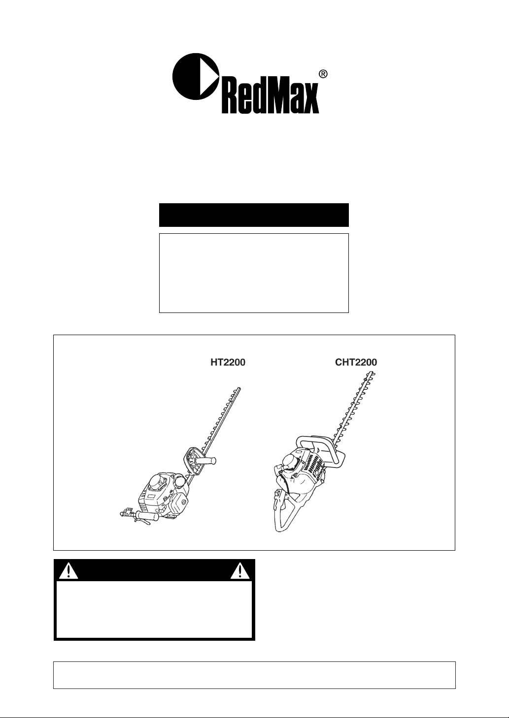
OWNER/OPERATOR MANUAL
HEDGE-TRIMMERS
HT2200
CHT2200
Thank you for purchasing a RedMax
product.
Before using our hedge-trimmers,
please read this manual carefully to
understand the proper use of your unit.
848-D13-93A1 (501)
HT2200 CUTTING UNIT 900101 and up ENGINE UNIT 50100000 and up
CHT2200 CUTTING UNIT 900101 and up ENGINE UNIT 50100000 and up
APPLICABLE SERIAL NUMBERS :
Page 2
Read this manual carefully to understand all
safety precautions, controls, proper operation
and maintenance of your RedMax hedgetrimmers. Failure to do so could result in
serious injury.
Instructions labeled as shown at left, concern critical steps or
procedures which must be followed in order to prevent accidents
which could lead to serious bodily injury or death.This mark is
used to indicate instructions which must be followed without
exception.
Instructions labeled as shown at left concern steps or procedures
which, if not followed correctly, could lead to mechanical failure,
breakdown, or damage.
Used to label supplementary instructions designed to provide
hints or directions useful in the use of the product.
WARNING
IMPORTANT
NOTE
SAFETY FIRST
Instructions contained in warnings within this manual marked with a symbol
concern critical points which must be taken into consideration to prevent
possible serious bodily injury, and for this reason you are requested to read all
such instructions carefully and follow them without fail.
Note that there may be times when warning seals peel off or become soiled and
impossible to read. If this happens, you should contact the dealer from which
you purchased the product to order new seals and affix the new seal(s) in the
required location(s).
■ Notes on types of warnings
Page 3

CONTENTS
SAFETY PRECAUTIONS · · · · · · · · · · · · · · · · · · · · · · · · · · · · · · · · · · · · · · 4
PROPER AND SAFE OPERATION OF YOUR HEDGE-TRIMMER
WORK GEAR AND CLOTHING
WARNINGS CONSIDERING HANDLING OF FUEL
THINGS TO CHECK BEFORE USING YOUR HEDGE-TRIMMER
THINGS TO CHECK BEFORE STARTING UP THE ENGINE
AVOID NOISE PROBLEM
THINGS TO BE CAREFUL ABOUT WHEN USING YOUR HEDGE-TRIMMER
NOTES ON CARE AND MAINTENANCE OF YOUR HEDGE-TRIMMER
PARTS LOCATION & SPECIFICATIONS · · · · · · · · · · · · · · · · · · · · · · · · · 9
EMISSION CONTROL LABEL · · · · · · · · · · · · · · · · · · · · · · · · · · · · · · · · · 10
SET UP · · · · · · · · · · · · · · · · · · · · · · · · · · · · · · · · · · · · · · · · · · · · · · · · · · · · 11
HT2200
CHT2200
FUEL· · · · · · · · · · · · · · · · · · · · · · · · · · · · · · · · · · · · · · · · · · · · · · · · · · · · · · 13
HOW TO MIX FUEL
FUELING THE UNIT
OPERATION · · · · · · · · · · · · · · · · · · · · · · · · · · · · · · · · · · · · · · · · · · · · · · · 15
STARTING ENGINE
STOPPING ENGINE
ADJUSTING IDLING SPEED
HOW TO USE
MAINTENANCE · · · · · · · · · · · · · · · · · · · · · · · · · · · · · · · · · · · · · · · · · · · · 17
DAILY INSPECTION
GEAR CASE
AIR FILTER
FUEL FILTER
SPARK PLUG
MUFFLER
SPARK ARRESTER
INTAKE AIR COOLING VENT
PROCEDURES TO BE PERFORMED AFTER EVERY 100 HOURS OF USE
STORAGE · · · · · · · · · · · · · · · · · · · · · · · · · · · · · · · · · · · · · · · · · · · · · · · · · 20
PARTS LIST
HT2200 · · · · · · · · · · · · · · · · · · · · · · · · · · · · · · · · · · · · · · · · · · · · · · · · 22
CHT2200 · · · · · · · · · · · · · · · · · · · · · · · · · · · · · · · · · · · · · · · · · · · · · · · 26
Page 4
4
■
IN ORDER TO ENSURE PROPER AND SAFE
OPERATION OF YOUR HEDGE-TRIMMER
• This product has been designed for use in
trimming leaves and branches from trees
and hedges, and it should never be used
for any other purpose since doing so could
result in unforeseen accidents and injuries
occurring.
• This product is equipped with extremely
sharp blades, and when used improperly
these blades can be extremely dangerous.
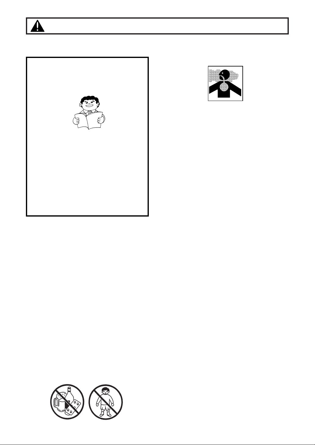
For this reason, you should never use this
hedge-trimmer when under the influence of
alcohol, when suffering from exhaustion or
lack of sleep, when suffering from
drowsiness as a result of having taken cold
medicine, or at any other time when a
possibility exists that your judgment might
be impaired or that you might not be able to
operate the hedge-trimmer properly and in
a safe manner. Also be sure never to allow
children or anyone unable to fully
understand the directions given in this
manual to use this hedge-trimmer.
Safety Precautions
• Avoid running the engine indoors. The
exhaust gases contain harmful carbon
monoxide.
• Never use your hedge-trimmer under
circumstances like those described below:
1. When the ground is slippery or when
other conditions exist which might make
it not possible to maintain a steady
posture while using the hedge-trimmer.
2. At night, at times of heavy fog, or at any
other times when your field of vision
might be limited and it would be difficult
to gain a clear view of the area where
the hedge-trimmer is to be used to
ensure safety.
3. During rain storms, during lightning
storms, at times of strong or gale-force
winds, or at any other times when
weather conditions might make it unsafe
to use this product.
•When using this product for the first time,
before beginning actual work, take the
hedge-trimmer to a wide, clear, open
space, turn on the power, and practice
handling the hedge-trimmer until you are
sure that you will be able to handle in it
properly in actual operation.
• Lack of sleep, tiredness, or physical
exhaustion results in lower attention spans,
and this in turn leads to accidents and
injury. When planning your work schedule,
allow plenty of time to perform the work of
trimming and allow plenty of time for rest.
Limit the amount of time over which the
hedge-trimmer is to be used continuously
to somewhere around 30~40 minutes per
session, and take 10~20 minutes of rest
between work sessions. Also try to keep
the total amount of work performed in a
single day under 2 hours or less.
• Read this Owner/Operator Manual
carefully. Be sure you understand how to
operate this unit properly before you use
it. Failure to do so could result in serious
injury.
• Be sure to keep this manual handy so
that you may refer to it later whenever
any questions arise. Also note that you
are requested to contact the dealer from
whom you purchased the product for
assistance in the event that you have any
questions which cannot be answered
herein.
• Always be sure to include this manual
when selling, lending, or otherwise
transferring the ownership of this product.
Page 5
Safety Precautions
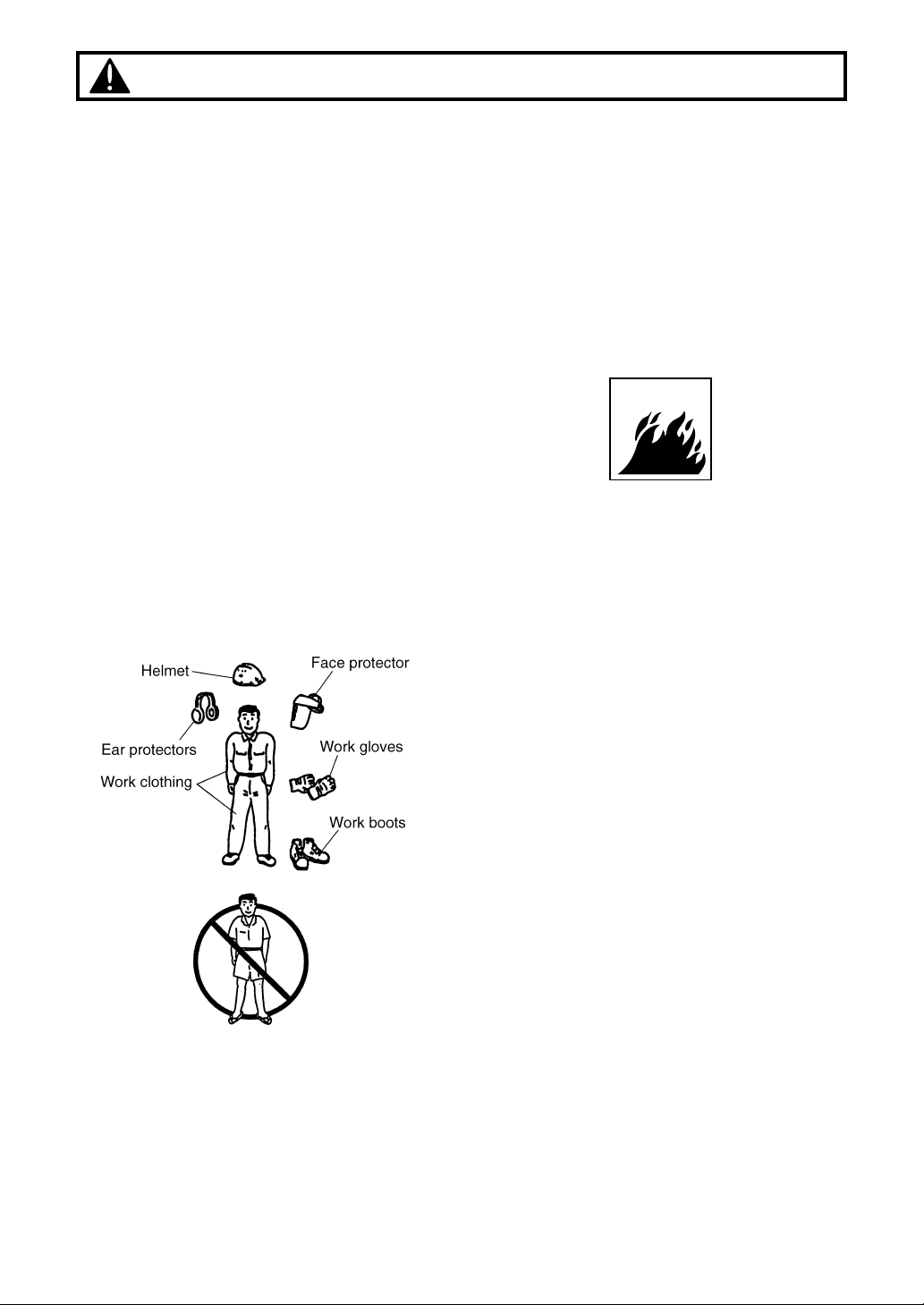
■ WORK GEAR AND CLOTHING
•When using your hedge-trimmer, always be
sure to wear strong, durable, work clothing;
shirts should be long-sleeved shirts and
pants should be full-length pants reaching
down to the ankles.
• Always be sure to wear and helmet and
face protector when using your hedgetrimmer.
•When using your hedge-trimmer, always be
sure to wear thick work gloves to protect
your hands and non-slip-sole work boots to
prevent you from slipping. Never use your
hedge-trimmer when wearing pants with
loose cuffs, when wearing sandals, or
when barefoot.
•When using your hedge-trimmer for an
extended period of time, you should wear
ear protectors to protect yourself from loss
of hearing from overexposure to high levels
of sound.
■
WARNINGS CONSIDERING HANDLING OF FUEL
• The engine of the RedMax hedge-trimmer
is designed to run on a mixed fuel which
contains highly flammable gasoline. This
fuel is highly flammable and you should
never store cans of fuel or refill the tank of
the hedge-trimmer in any place where
there is a boiler, stove, wood fire, electrical
sparks, welding sparks, or any other source
of heat or fire which might ignite the fuel.
• Smoking while operating the hedge-trimmer
or refilling its fuel tank is extremely
dangerous. Always be sure to keep lit
cigarettes away from the hedge-trimmer at
all times.
• When refilling the tank always turn off the
engine first and take a careful look around
to make sure that there are no sparks or
open flames anywhere nearby before
refueling.
• If any fuel spillage occurs during refueling,
always be sure to use a dry rag to wipe any
fuel which has been spilled onto the hedgetrimmer before turning the engine back on
again.
• After refueling, screw the fuel cap back
tightly onto the fuel tank and then carry the
hedge-trimmer to a spot 10 feet or more
away from where it was refueled before
turning on the engine.
5
Page 6
6
Safety Precautions
■
THINGS TO CHECK BEFORE USING YOUR
HEDGE-TRIMMER
• Before beginning work, look around
carefully to get a feel for the shape of the
land, the trees, or hedges to be trimmed,
and whether or not there are any obstacles
which might get in the way while working,
and remove any obstacles which can be
cleared away before beginning work.
• The area within a perimeter of 45 feet of the
person using the hedge-trimmer should be
considered a hazardous area into which no
one should enter while the hedge-trimmer
is in use, and when necessary yellow
warning rope, warning signs, or some other
form of warnings should be placed around
the perimeter of the area. When work is to
be performed simultaneously by two or
more persons, care should also be taken to
constantly look around or otherwise check
for the presence and locations of other
people using hedge-trimmers within the
work area so as to maintain a distance
between each person sufficient to ensure
safety.
• Before beginning work, each component of
the hedge-trimmer should be checked to
make sure that it is in proper working order
and to make sure that there are no loose
screws or bolts, fuel leaks, ruptures, dents,
or any other problems which might interfere
with safe operation. Be especially careful at
this time to check that there is nothing
wrong with the blades or with the joints by
which the blades are attached to the
hedge-trimmer.
•Never use the hedge-trimmer when the
blades have been worn down severely or
when there is any sort of damage which
has occurred to the blade mechanism.
• Check to make sure that the handle grip
and the protective cover have not come
loose before using the hedge-trimmer.
■
THINGS TO CHECK BEFORE STARTING
UP THE ENGINE
• Take a careful look around to make sure
that no obstacles exist within a perimeter of
15 feet or less around the hedge-trimmer
before starting the engine.
• The RedMax hedge-trimmer is equipped
with a centrifugal clutch mechanism which
causes the cutting blades to begin to rotate
as soon as the engine is started by putting
the throttle into the start position. When
starting the engine, place the body of the
hedge-trimmer onto the ground in a flat
clear area and hold it firmly in place so as
to ensure that neither the blades nor the
throttle come into contact with any
obstacles when the engine starts up.
• Never place the throttle into the high speed
position when starting the engine.
• After starting up the engine, check to make
sure that the blades stop rotating when the
throttle is moved fully back to its original
position. If the blades continue to rotate
even after the throttle has been moved fully
back, turn off the engine and take the unit
to your authorized RedMax servicing dealer
for repair.
■ AVOID NOISE PROBLEM
Check and follow the local regulations
as to sound level and hours of
operations for hedge-trimmer.
•In general, operate hedge-trimmers
between 8a.m.and 5p.m.on week days and
9a.m.to 5p.m.weekends. Avoid using
hedge-trimmer late at night and/or early in
the morning.
NOTE
Page 7
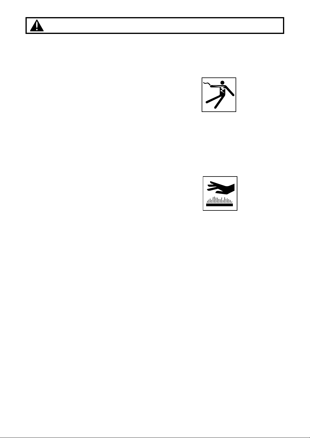
• Never touch the spark plug or plug cord
while the engine is in operation. Doing so
may result in being subjected to an
electrical shock.
• Never touch the muffler, spark plug, or
other metallic parts of the engine while the
engine is in operation or immediately after
shutting down the engine. These metallic
parts reach high temperatures during
operation and doing so could result in
serious burns.
• When you finish trimming in one location
and wish to continue work in another spot,
turn off the engine, place the protective
cover over the blades, and turn the hedgetrimmer so that the blades face away from
your body before carrying it to the new
location.
•Never transport the hedge-trimmer over
rough roads over long distances without
first removing all fuel from the fuel tank, as
doing so might cause fuel to leak from the
tank as a result of shocks absorbed during
transport.
Safety Precautions
■
THINGS TO BE CAREFUL ABOUT WHEN
USING YOUR HEDGE-TRIMMER
•When using your hedge-trimmer, grip the
handles of the hedge-trimmer firmly with
both hands, place your feet slightly apart
(slightly further apart than the width of your
shoulders) so that your weight is distributed
evenly across both legs, and always be
sure to maintain a steady, even posture
while working.
•Maintain the speed of the engine at the
level required to perform trimming work,
and never raise the speed of the engine
above the level necessary.
• Always be sure never to allow other
persons to come within the work area while
trimming.
• Be especially careful not to slip if it is
raining or if rain has just stopped, as the
ground is likely to be slippery at such times.
• If a branch or other object gets caught in
the blades during operation, always be
sure to turn off the engine before removing
the object.
• Guard against hazardous situations at all
times. Warn adults to keep pets and
children away from the area. Establish a
safe method for gaining your attention
during operation. Be careful if you are
approached.
• To protect yourself against injury from
falling branches, always be sure to wear
the required safety equipment, and be
careful when working to watch to see in
which direction branches are moving and
falling so as to avoid being hit by falling
branches.
• If someone calls out or otherwise interrupts
you while working, always be sure to turn
off the engine before turning around.
• Keep operation area clear of all persons,
particularly small children and pets. Injury
may result from flying debris.
7
Page 8

Safety Precautions
8
■
NOTES ON CARE AND MAINTENANCE OF
YOUR HEDGE-TRIMMER
•In order to maintain your hedge-trimmer in
proper working order, perform the
maintenance and checking operations
described in this manual at regular
intervals. In the event that any parts must
be replaced or any maintenance or repair
work not described in this manual must be
performed, please contact a representative
from the store nearest RedMax authorized
servicing dealer for assistance.
• Under no circumstances should you ever
take apart the hedge-trimmer or alter it in
any way. Doing so might result in the
hedge-trimmer becoming damaged during
operation or the hedge-trimmer becoming
unable to operate properly.
• Always be sure to turn off the engine before
performing any maintenance or checking
procedures.
•When sharpening, removing, or reattaching
the blades, be sure to wear thick, sturdy
gloves and use only proper tools and
equipment to prevent injury.
•When replacing blades or any other parts
or when replacing the oil or any lubricants,
always be sure to use only RedMax
products or products which have been
certified by RedMax for use with the
RedMax hedge-trimmer.
• Do not use any accessory or attachment
other than those bearing the RedMax mark
and recommended for the unit.
Page 9
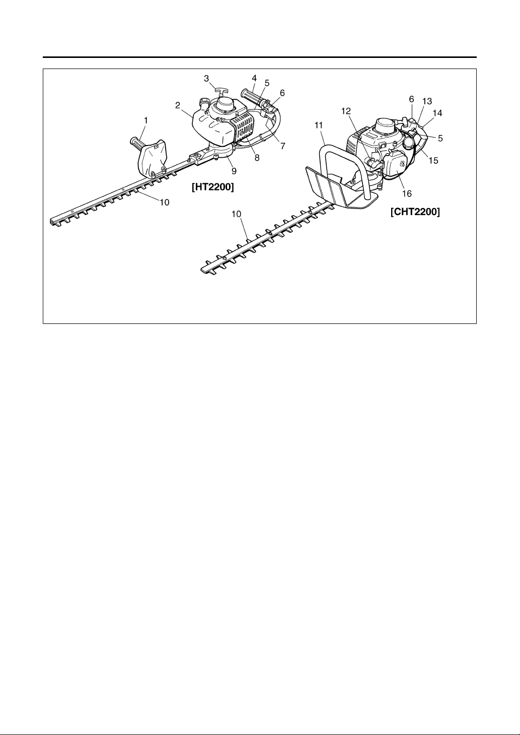
Parts Location & Specifications
■ HT2200
Type ·············································································Reciprocating single-sided dual blades
Blade size ·······················································································································24 (in)
Dry weight ····················································································································9.5 (lbs)
Engine Type ··········································································Air-cooled 2-stroke gasoline
Model ····························································································Zenoah G23LH
Displacement ····························································································22.5(cc)
Fuel ··············································································Mixture(Gasoline 50:Oil 1)
Carburetor ········································································Walbro Diaphragm type
Spark plug ·················································································Champion RCJ6Y
Fuel tank capacity ·······································································································20 (fl.oz)
Transmission ·············································································Centrifugal clutch, Cam-crank
Reduction ratio ···················································································································4.33
■ CHT2200
Type ·············································································Reciprocating duble-sided dual blades
Blade size ·······················································································································22 (in)
Dry weig ·······················································································································9.5 (lbs)
Engine Type ··········································································Air-cooled 2-stroke gasoline
Model ····························································································Zenoah G23LH
Displacement ····························································································22.5(cc)
Fuel ··············································································Mixture(Gasoline 50:Oil 1)
Carburetor ········································································Walbro Diaphragm type
Spark plug ·················································································Champion RCJ6Y
Fuel tank capacity ·······································································································20.(fl.oz)
Transmission ·············································································Centrifugal clutch, Cam-crank
Reduction ratio ···················································································································4.33
Specifications are subject to change without notice.
1. Right handle
2. Fuel tank
3. Starter
4. Left handle
5. Throttle lever
6. Ignition switch
7. Throttle Cable
8. Muffler
9. Clutch housing
10. Blade
11. Front handle
12. Spark plug
13. Lock button
14. Stopper
15. Rear handle
16. Air cleaner
9
Page 10

10
Emission Control Label
IMPORTANT ENGINE INFORMATION
THIS ENGINE CONFORMS TO 2005 U.S. EPA
REGULATIONS FOR SMALL NONROAD ENGINES.
COMPLIANCE PERIOD : CATEGORY A
ENGINE FAMILY : 5KZXS. 0254CD : EM
ENGINE DISPLACEMENT : 23cc
REFER TO OWNER’S MANUAL FOR MAINTENANCE SPECIFICATIONS AND ADJUSTMENTS.
KOMATSU ZENOAH CO.
MANUFACTURED:
RedMax
MADE IN JAPAN
INFORMATION IMPORTANTE CONCERNANT LE MOTEUR
KOMATSU ZENOAH CO.
RedMax
CE MOTEUR EST CONFORME A LA REGLEMENTATION
U.S. EPA 2005 POUR LES PETITS MOTEURS HORS-ROUTE.
DUREE DE CONFORMITE : CATEGORIE A
TYPE DE MOTEUR : 5KZXS.0254CD ; EM
CYLINDREE DU MOTEUR : 23 cc
SE REFERER AU MANUEL DE L’UTILISATEUR POUR LES
SPECIFICATIONS D’ENTRETIEN ET LES REGLAGES.
FABRIQUE PAR :
MADE IN JAPAN
Page 11

11
Set up
■ HT2200
1. Join the engine unit to the clutch housing
of the cutter unit, with the fuel tank on the
blade side.
2. Align the mounting holes and tighten the
engine securely with the 3 screws.
3. Remove the right handle mounting screw,
nut, and washer casually attached on the
blade beam.
4. Set the right handle on the beam making
the grip come to the opposite side of the
cutting teeth, and attach with the hardware
removed before. When fastening the nut,
hold the screw to keep the blade washer
loose.
• To assure designed cutting performance,
always keep a half spare turn for the blade
screws. Over tightening will cause blade
seizure and premature wear of the clutch
system. Too loose screws will make the
gap between the blades large, and result in
poor cutting performance.
NOTE
5. Install the left handle to the bracket
attached to the clutch housing. Use the
hardware as shown below.
7. Cover the throttle cable with colgate tube.
Connect the throttle cable and the switch
wire. Hold the wires at the lower part of
the handle using the tie band.
8. Check the cable play and, if necessary,
adjust between .04” and .08” by bending
throttle wire receiver of the bracket with
needle nose pliers.
BLADE WASHER
(Keep Loose)
Page 12

12
■ CHT2200
1. Attach the engine to the clutch housing of
the cutter unit. Casually fix the front 2
points with the screws(.55" long).
2. After connecting the ground wire, install
the rear handle to the clutch housing with
the screw(2" long) and the nut.
3. Put the screw(1.6" long) through the
ground wire terminal and the rear handle,
and in to the engine mounting base.
Securely tighten all of the engine mounting
screws.
4. Attach the front handle onto the gear
housing and fasten with 2 screws(1.2"
long) and nuts.
5. Connect the throttle cable with the lever
on the rear handle, and secure the end
with the hardware attached to the handle.
6. Check the cable play and, if necessary,
adjust between .04” and .08” by bending
throttle wire receiver of the bracket with
needle nose pliers.
Set up
Page 13

Fuel
■ RECOMMENDED MIXING RATIO
GASOLINE 50:OIL 1
• Exhaust emission are controlled by the
fundamental engine parameters and
components(eq., carburation, ignition
timing and port timing) without
addition of any major hardware or the
introduction of an inert material during
combustion.
• These engines are certified to operate on
unleaded gasoline.
• Make sure to use gasoline with a
minimum octane number of 89 RON
(USA/Canada: 87AL)
• If you use a gasoline of a lower octane
value than prescribed, there is a danger
that the engine temperature may rise and
an engine problem such as piston seizing
may consequently occur.
• Unleaded gasoline is recommended to
reduce the contamination of the air for the
sake of your health and the environment.
• Poor quality gasolines or oils may damage
sealing rings, fuel lines or fuel tank of the
engine.
■ HOW TO MIX FUEL
Pay attention to agitation.
1. Measure out the quantities of gasoline
and oil to be mixed.
2. Put some of the gasoline into a clean,
approved fuel container.
3. Pour in all of the oil and agitate well.
4. Pour In the rest of gasoline and agitate
IMPORTANT
• Gasoline is very flammable. Avoid
smoking or bringing any flame or
sparks near fuel. Make sure to stop the
engine and allow it cool before
refueling the unit. Select outdoor bare
ground for fueling and move at least
3m (10ft) away from the fueling point
before starting the engine.
• The RedMax engines are lubricated by oil
specially formulated for air-cooled 2-cycle
gasoline engine use. If RedMax oil is not
available, use an anti-oxidant added
quality oil expressly labeled for air-cooled
2-cycle engine use. (JASO FC GRADE
OIL or ISO EGC GRADE)
• Do not use BIA or TCW (2-stroke watercooling type) mixed oil.
WARNING
50:1 MIXING CHART
GASOLINE gal. 1 2 3 4 5
2-CYCLE OIL fl.oz 2.6 5.2 7.8 10.4 13
GASOLINE liter 1 2 3 4 5
2-CYCLE OIL ml 20 40 60 80 100
13
Page 14

14
Fuel
again for at least one minute. As some
oils may be difficult to agitate depending
on oil ingredients, sufficient agitation is
necessary for the engine to last long. Be
careful that, if the agitation is insufficient,
there is an increased danger of early
piston seizing due to abnormally lean
mixture.
5. Put a clear indication on the outside of the
container to avoid mixing up with gasoline
or other containers.
6. Indicate the contents on outside of
container for easy identification.
■ FUELING THE UNIT
1. Untwist and remove the fuel cap. Rest the
cap on a dustless place.
2. Put fuel into the fuel tank to 80% of the full
capacity.
3. Fasten the fuel cap securely and wipe up
any fuel spillage around the unit.
1. Select bare ground for fueling.
2. Move at least 10feet (3meters) away
from the fueling point before starting
the engine.
3. Stop the engine before refueling the
unit. At that time, be sure to sufficiently
agitate the mixed gasoline in the
container.
FOR YOUR ENGINE LIFE, AVOID;
1. FUEL WITH NO OIL(RAW GASOLINE) –
It will cause severe damage to the internal
engine parts very quickly.
2. GASOHOL – It can cause deterioration of
rubber and/or plastic parts and disruption
of engine lubrication.
3. OIL FOR 4-CYCLE ENGINE USE – It can
cause spark plug fouling, exhaust port
blocking, or piston ring sticking.
4. Mixed fuels which have been left
unused for a period of one month or
more may clog the carburetor and result
in the engine failing to operate properly.
WARNING
5. In the case of storing the product for a
long period of time, clean the fuel tank
after rendering it empty. Next, activate the
engine and empty the carburetor of the
composite fuel.
6. In the case of scrapping the used mixed
oil container, scrap it only at an authorized
repository site.
As lot details of quality assurance, read the
description in the section Limited Warranty
carefully. Moreover, normal wear and
change in product with no functional
influence are not covered by the warranty.
Also, be careful that, if the usage in the
instruction manual is not observed as to the
mixed gasoline, etc. described therein, it
may not be covered by the warranty.
NOTE
Page 15

■ STARTING ENGINE
• Keep the blades clear of the
surrounding as they will start moving
upon starting of the engine.
1. When first starting up after putting fuel into
the machine, push the priming pump until
fuel runs out in the clear tube. Then close
the choke. Choking may not be necessary
when re-starting right after stopping the
engine.
2. Pull the throttle lever and push the lock
button to set the lever in the START
position.
3. Slide the ignition switch to the engine side
to set it in the ON position.
WARNING
Operation
4. Rest the unit on a firm place. Pull the
starter knob quickly.
• Avoid pulling the rope to its end or returning
it by releasing the knob. Such actions can
cause starter failures.
5. When the engine has started, gradually
open the choke.
6.Allow the engine to warm up for a half
minute before starting operation.
• If the engine won't start after several
attempts, open the choke and repeat
pulling the rope or remove the spark plug
and dry it.
NOTE
NOTE
15
Page 16
16
Operation
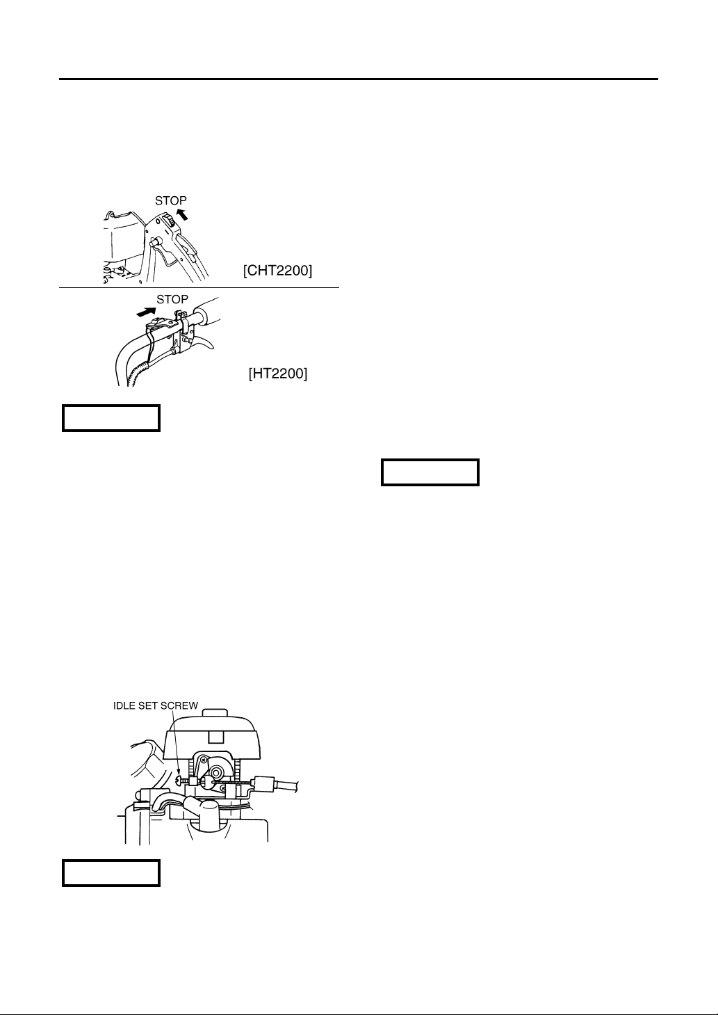
■ ADJUSTING IDLING SPEED
1. When the engine tends to stop frequently
at idling mode, turn the idle set screw
clock-wise.
2.When the cutting blades keep moving after
releasing the throttle trigger, turn the idle
set screw counter-clockwise.
•Warm up the engine before adjusting the
idling speed.
NOTE
■ HOW TO USE
• This machine is designed so as to cut
twigs upto 8 mm(0.3 inches) thick.
Cutting too thick twigs or metal wires
can not only break the blade teeth but
also give damage to the drive
mechanism.
•When trimming leaves and thin twigs, guide
the blades as drawing a half circle on the
surface, and you will get a better finish.
• Running the engine at high speed with the
blades Jammed up can shorten the life of
clutch parts. When the blades have been
jammed by thick twigs, stop operation at
once and draw your unit off the objects
after stopping the engine. When clipping
comparatively thick twigs, move your unit
slowly back and forth like a saw, and they
can be cut to a fine finish.
•When a new unit is first operated, in the
first few minutes grease may come out of
the gear case. But, since this is excess
grease, there is no cause for alarm. For
next use just wipe it off with the engine
stopped.
NOTE
■ STOPPING ENGINE
1. Release the throttle lever and run the
engine at idling speed for a half minute.
2. Slide the ignition switch to the STOP
position.
• Except for an emergency, avoid stopping
the engine while running it at high speed.
NOTE
Page 17
Maintenance
•Make sure that the engine has stopped
and is cool before performing any
service to the hedge-trimmer. Contact
with moving cutting head or hot muffler
may result in a personal injury.
■ DAILY INSPECTION
• Check all the fasteners for loose or missing
ones.
• Brush off dirt on the blades and apply a
light coating of oil.
• The blades are loose-installed to the guide
bar with several screws and nuts. Do not
tighten up those screws, or the blades will
be locked and result in clutch failures.
Allow the screws a half spare turn, and
secure there with the nut(See NOTE on
page 8).
■ GEAR CASE
• At every 15 hours of use, supply grease to
the gear case. Pump in grease via the
grease fitting until it comes out of the root
of blades.
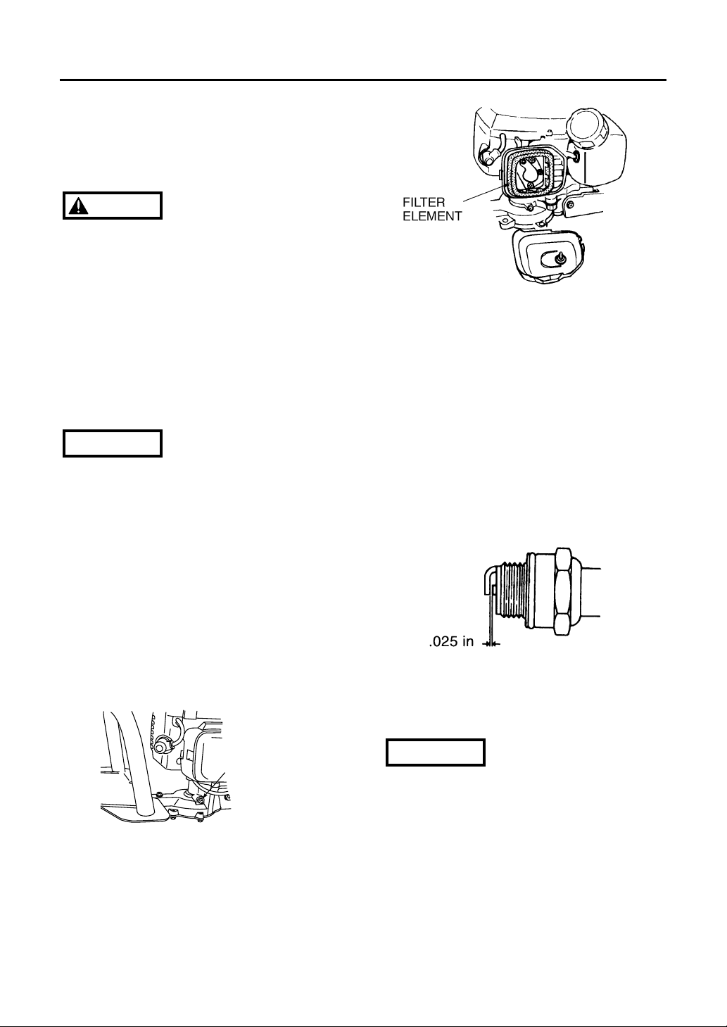
■ AIR FILTER
• The air filter, if clogged, will reduce the
engine performance. Monthly check and
clean the filter element in warm, soapy
water as required. Dry completely before
installing. If the element is broken or
shrunk, replace with a new one.
NOTE
■ FUEL FILTER
•When the engine runs short of fuel supply,
check the fuel cap and the fuel filter for
blockage.
■ SPARK PLUG
• Starting failure and mis-firing are often
caused by a fouled spark plug. Periodically
clean the spark plug and check that the
spark gap is in the correct range. For a
replacement plug, use the correct type
specified by RedMax(See SPECIFICATIONS on the page 15).
• REPLACEMENT PLUG IS A CHAMPION
RCJ6Y OR THE EQUIVALENT, SUCH AS
BOSCH WR8E OR NGK BR6S.
• Note that using any spark plugs other than
those designated may result in the engine
failing to operate properly or in the engine
becoming overheated and damaged.
• To install the spark plug, first turn the plug
until it is finger tight, then tighten it a
quarter turn more with a socket wrench.
IMPORTANT
17
Maintenance, replacement, or repair of
the emission control device and systems
may be performed by any non-road
engine repair establishment or individual.
WARNING
GREASE FITTING
Page 18
18
overheated, and that this in turn could
cause the hedge-trimmer to catch on
fire. Always make sure that the muffler
is clean and free of wood chips, leaves,
and other waste before use.
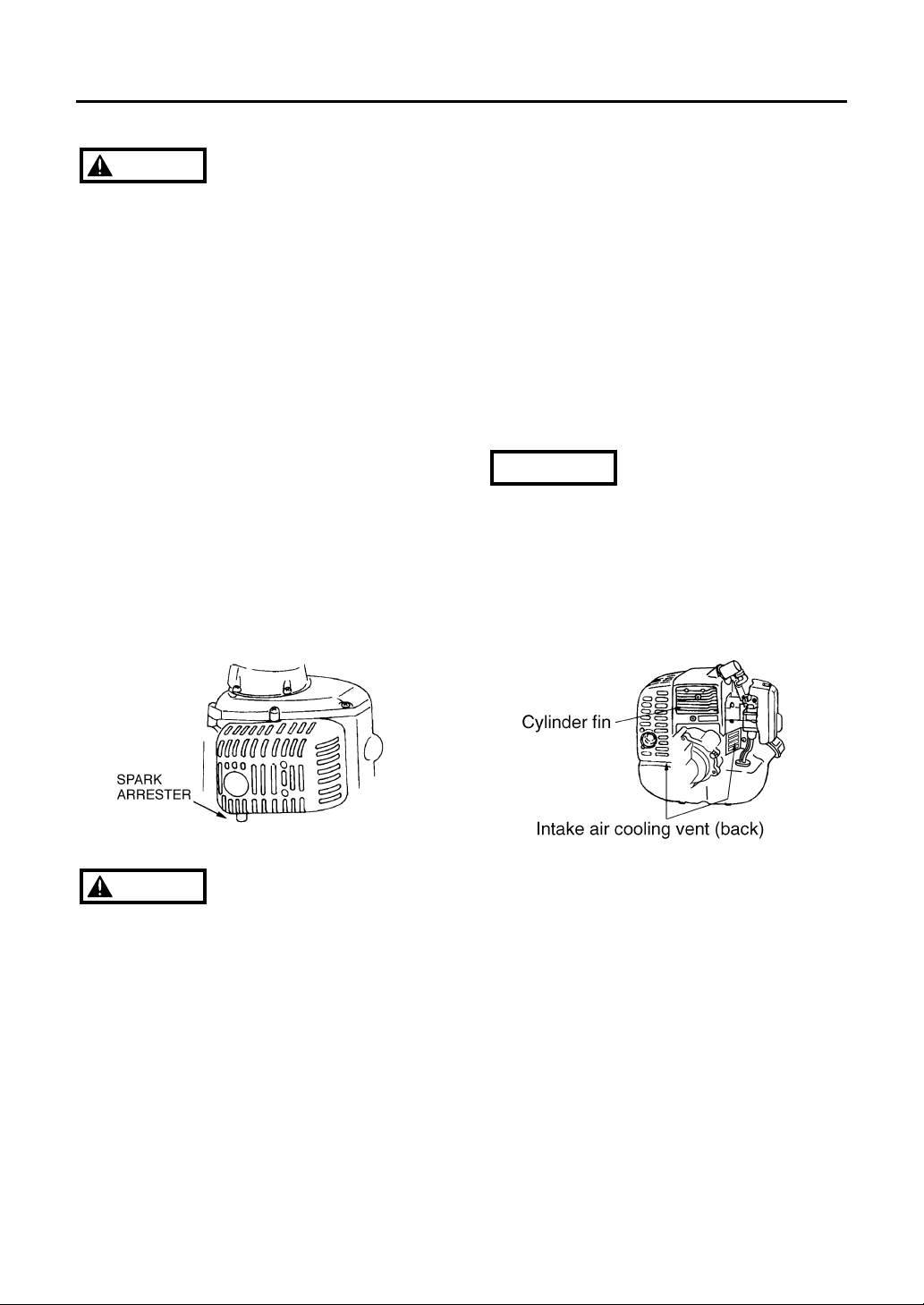
• Check the intake air cooling vent and the
area around the cylinder cooling fins after
every 25 hours of use for blockage, and
remove any waste which has attached itself
to the hedge-trimmer. Note that it is
necessary to remove the plug guard shown
below in order to be able to view the upper
part of the cylinder.
• If waste gets stuck and causes blockage
around the intake air cooling vent or
between the cylinder fins, it may cause the
engine to overheat, and that in turn may
cause mechanical failure on the part of the
hedge-trimmer.
IMPORTANT
Maintenance
■ MUFFLER
• Inspect periodically, the muffler for loose
fasteners, any damage or corrosion. If any
sign of exhaust leakage is found, do not
use the hedge-trimmer and have it repaired
immediately.
• Note that failing to do so may result in
the engine catching on fire.
■ SPARK ARRESTER
• The muffler is equipped with a spark
arrester to prevent red hot carbon from
flying out of the exhaust outlet. Periodically
inspect and clean as necessary with a wire
brush. In the State of California it is
required by law (Section 4442 of the
California Public Resources Code) to equip
a spark arrester when a gas powered tool
is used in any forest covered, brush
covered, or grass covered unimproved
land.
■ INTAKE AIR COOLING VENT
•Never touch the cylinder, muffler, or
spark plugs with your bare hands
immediately after stopping the engine.
The engine can become very hot when
in operation, and doing so could result
in severe burns.
• When checking the hedge-trimmer to
make sure that it is okay before using it,
check the area around the muffler and
remove any wood chips or leaves which
have attached themselves to the hedgetrimmer. Note that failing to do so could
cause the muffler to become
WARNING
WARNING
Page 19

Maintenance
■ PROCEDURES TO BE PERFORMED
AFTER EVERY 100 HOURS OF USE
1. Remove the muffler, insert a screwdriver
into the vent, and wipe away any carbon
buildup. Wipe away any carbon buildup on
the muffler exhaust vent at the same time.
2. Tighten all screws, bolts, and fittings.
3. Check to see if any oil or grease has
worked its way in between the clutch lining
and drum, and if it has wipe it away using
oil-free, lead-free gasoline.
19
Page 20

20
Storage
• Old fuel left in the carburetor can cause
starting failure. Before storing the unit,
empty the fuel tank and drain the
carburetor with the priming pump equipped
on it.
Page 21

Parts List
NOTE :
1. Use KOMATSU ZENOAH genuine parts as specified in the parts list for repair and/or
replacement.
2. KOMATSU ZENOAH does not warrant the machines, which have been damaged by the
use of any parts other than those specified by the company.
3. When placing parts orders for repair and/or replacement, check if the model name and the
serial number are applicable to those specified in the parts list, then use parts number
described in the parts list.
4. The contents described in the parts list may change due to improvement.
5. The parts for the machine shall be supplied seven (7) years after the machine is
discontinued. [It is possible that some specific parts may be subject to change of their
delivery term and list price within the limit of seven (7) years after the machine is
discontinued. It is also possible that some parts may be available even after the limit of
seven (7) years.]
21
HEDGE-TRIMMERS
HT2200
CHT2200
Mar. 2001
HT2200 CUTTING UNIT 900101 and up ENGINE UNIT 50100000 and up
CHT2200 CUTTING UNIT 900101 and up ENGINE UNIT 50100000 and up
APPLICABLE SERIAL NUMBERS :
Page 22
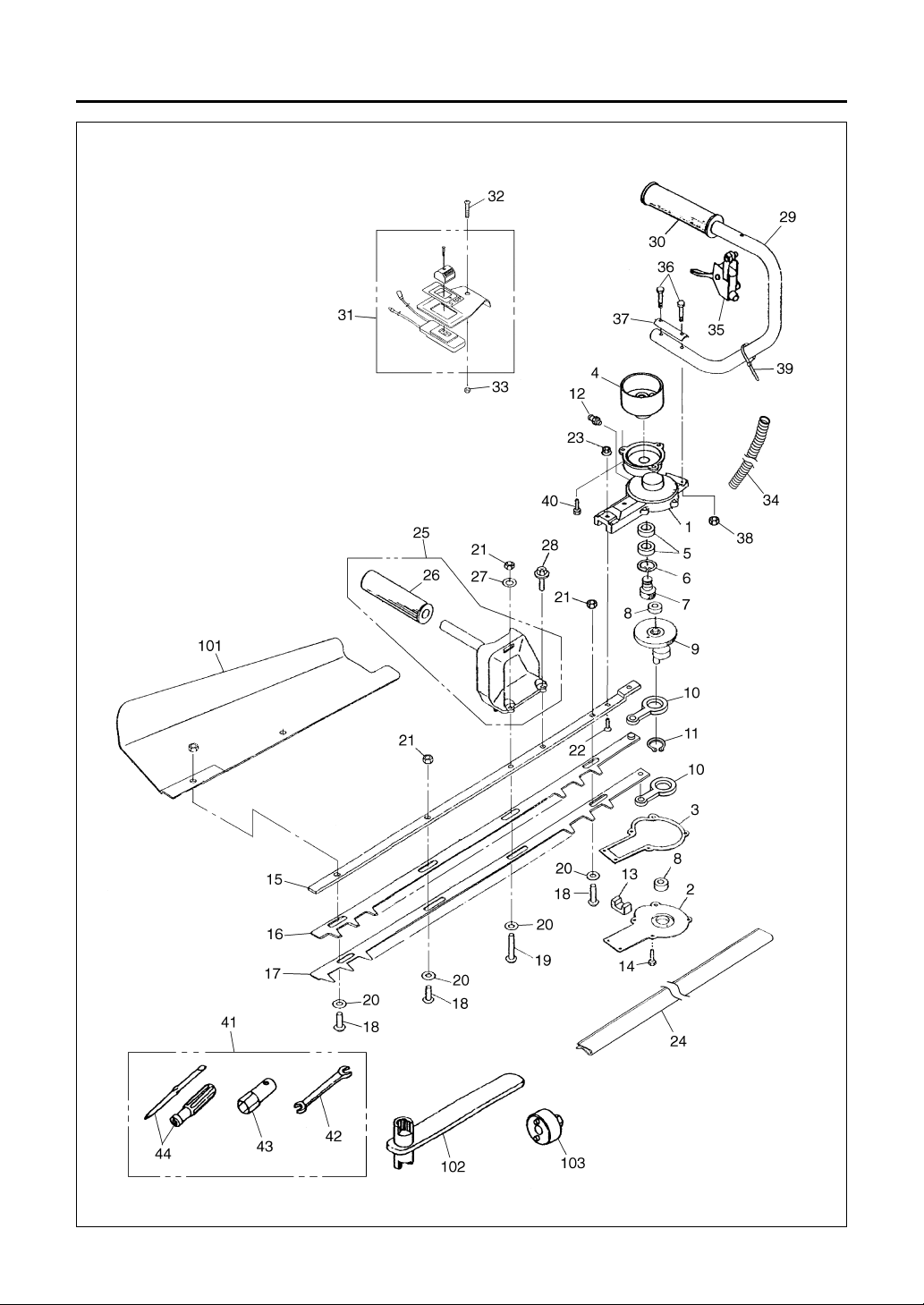
Fig.1 CUTTER GROUP — HT2200
22
Parts List
Page 23

Fig.1 CUTTER GROUP — HT2200
23
Parts List
Key# Description Part Number Q'ty Note
1 Gear case T4001-31110 1
2 Cover T4001-31210 1
3 Gasket T4001-31220 1
4 Drum 3884-11410 1
5 Bearing 06004-06001 2
6 Snap ring T4001-31320 1
7Pinion T4001-31330 1
8 Bearing T4001-31340 2
9 Gear comp. T4001-31350 1
10 Rod T4001-31510 2
11 Snap ring 04064-02512 1
12 Fitting 3199-13350 1
13 Felt T4001-31360 1
14 Bolt T4001-31370 6 M5x12
15 Guide plate T4001-32110 1
16 Upper blade T4001-32210 1
17 Lower blade T4001-32220 1
18 Screw(L:19) 3884-11750 3
19 Screw(L:29) 6095-11810 1
20 Washer 3880-11780 4
21 Nut 3880-11790 4
22 Screw T4001-32310 2 M5x16
23 Nut T4001-32320 2
24 Cover, blade T4001-32910 1
25 Handle comp. 6844-12100 1
26 • Grip 3880-13121 1
27 Washer 3883-12130 1
28 Bolt 3883-12140 1 M6x18
29 Handle comp. T4001-34100 1
30 • Grip 3880-13121 1
31 Switch T4001-74100 1
32 Screw 0263-00525 1
33 Nut 0280-10504 1
34 Tube T4001-74310 1
35 Lever assy 3881-13210 1
36 Bolt 0212-50525 2
37 Plate 6095-13310 1
38 Nut 3876-14470 2
39 Band 3880-13350 1
40 Bolt 0225-10614 3
41 Tool set 1111-91003 1
42 • Spanner 3540-91120 1
43 • Socket 1110-91320 1
44 • Driver 1030-91340 1
101 Receive plate 3885-91110 1 OP
102 Wrench 3880-95020 1 OP
103 Wrench 3880-95010 1 OP
Key# Description Part Number Q'ty Note
Page 24
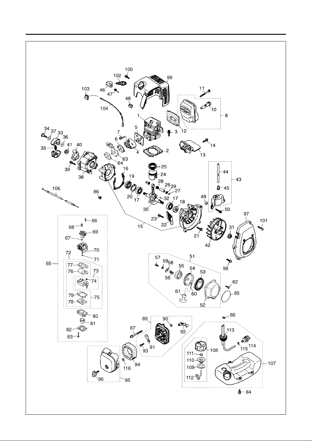
Fig.2 ENGINE GROUP — HT2200
24
Parts List
Page 25

Key# Description Part Number Q'ty Note
1 Cylinder 5602-12110 1
2 Gasket, base 5500-12213 1
3 Bolt, M5x22 1850-12130 2
4 Insulator 5500-13163 1
5 Gasket, insulator 5500-13121 1
6 Gasket, carb 5500-13131 1
7 Screw, M5x20 0263-90520 2
8 Muffler assy 5602-15100 1
10 • Spark arrester 1601-15120 1
11 Bolt, M5x50 01252-30550 2
12 Gasket, muffler 5600-15210 1
13 Plate, muffler 5600-15220 1
14 Screw, M4x16 0263-90416 1
15 Crancase comp. 5600-21100 1
16 Gasket, case 5500-21141 1
17 Bearing 06030-06001 2
18 Oil seal 2169-21210 1
19 Oil seal 1850-21220 1
20 Snap ring 04065-02812 1
21 Bolt, M5x30 01252-30530 4
22 Guard 5500-22110 1
23 Screw, M5x14 0263-90514 1
24 Piston 5600-41111 1
25 Ring, piston 1100-41210 2
26 Pin, piston 1101-41310 1
27 Snap ring 1260-41320 2
28 Bearing 5500-41410 1
29 Washer 1101-41340 2
30 Crankshaft comp. 5600-42001 1
31 Nut 1650-43230 1
32 Key 1000-43240 1
33 Shoe 1140-51111 2
34 Screw 1140-51250 2
35 Spring 1600-51223 1
36 Washer 1140-51230 2
37 Washer 1970-51241 2
38 Case, clutch 5600-52110 1
39 Screw, M5x16 0263-90516 4
40 Plate, clutch 5600-52150 1
41 Nut 1650-43230 1
42 Rotor 5601-71110 1
43 Coil assy 5600-71200 1
44 • Cord 5600-71220 1
45 • Cap 2616-71320 1
46 Cap, spark plug 5500-72110 1
47 Spring 1900-72120 1
48 Grommet 5500-72130 1
49 Spacer 1260-71261 2
50 Bolt, M4x25 3310-72150 2
51 Recoil assy 5990-75102 1
52 • Case, recoil 5990-75110 1
53 • Spring, Spiral 5990-75120 1
54 • Reel 5990-75131 1
55 • Ratchet 5990-75141 1
56 • Spring 5990-75151 1
57 • Screw 5990-75270 1
58 • Retainer 5990-75160 1
59 • Washer 5990-75170 1
Key# Description Part Number Q'ty Note
60 • Rope 1861-75180 1
61 • Knob 1490-75181 1
62 Screw 0263-90412 4
63 Bracket 5628-83221 1
64 Gasket, carburetor 5500-13131 1
65 Carburetor assy 5602-81001 1 WYL-55
66 • Screw 5850-81110 2
67 • Ring 1751-81130 1
68 • Swivel 1881-81140 1
69 • Valve assy ––––––––– 1
70 • O-ring 1751-81240 1
71 • Jet #37 5628-81250 1
72 • Rebuilt Kit 5602-06030 1
73 • • Body assy 1850-81450 1
74 • • • Screen ––––––––– –
75 • • Gasket Kit 5602-06020 1
76 • • •
Diaphragm, pump
––––––––– –
77 • • • Gasket, pump ––––––––– –
78 • • • Diaphragm ––––––––– –
79 • • •
Gasket, diaphragm
––––––––– –
80 • Body, purge 1850-81490 1
81 • Pump, priming 1751-81510 1
82 • Cover, pump 1850-81520 1
83 • Screw 1850-81530 4
84 Screw 5500-85510 3
85 Label, recoil T1038-91120 1
86 Cap 1601-81810 1
87 Screw, M5x60 0263-90560 2
88 Clip 1950-86120 1
89 Body assy 5500-82102 1
90 • Sleeve 1970-82190 2
91 • Plate, choke 5500-82131 1
92 • Lever, choke 5500-82140 1
93 • Screw 2630-33610 1
94 Element 5500-82171 1
95 Cover assy 5600-82203 1
96 • Knob 5500-82221 1
97 Cover, fan 5600-31110 1
98 Screw, M5x20 0263-90520 4
99 Cover, engine 5600-32101 1
100 Screw, M5x12 1850-32160 1
101 Screw 1900-31410 1
102 Spark plug 5602-73110 1 RCJ6Y
103 Grommet 1852-72121 1
104 Cord comp. 5500-73201 1
106 Cable comp. 1751-82101 1
107 Tank assy 5607-85002 1
108 • Cap assy 5607-85201 1
109 • • Packing 5500-85220 1
110 • • Holder 5601-85300 1
111 • • Filter 5601-85260 1
112 • • Stopper 4820-85260 1
113 • Pipe comp. 5500-85300 1
114 • Filter assy 5500-85400 1
115 • Clip 1260-85460 1
116 Clip 1950-86120 1
Fig.2 ENGINE GROUP — HT2200
25
Parts List
Page 26

Fig.3 CUTTER GROUP — CHT2200
26
Parts List
Page 27

Fig.3 CUTTER GROUP — CHT2200
27
Parts List
Key# Description Part Number Q'ty Note
1 Gear case T4002-31110 1
2 Cover T4002-31210 1
3 Gasket T4002-31220 1
4 Drum 3884-11410 1
5 Bearing 06004-06001 2
6 Snap ring T4001-31320 1
7Pinion T4001-31330 1
8 Bearing T4001-31340 2
9 Gear comp. T4001-31350 1
10 Rod T4001-31510 2
11 Snap ring 04064-02512 1
12 Fitting 3199-13350 1
13 Felt T4001-31360 1
14 Bolt T4001-31370 7 M5x12
15 Guide plate T4002-32110 1
16 Blade T4002-32210 2
17 Screw (L:19) 3884-11750 4
18 Washer 3880-11780 4
19 Nut 3880-11790 4
20 Screw T4001-32310 2 M5x16
21 Nut T4001-32320 2
22 Cover, blade T4002-32910 1
23 Handle (Front) T4002-33110 1
24 Bolt 0225-30635 2
25 Nut 0280-10605 2
26
Handle (Rear) Assy
6845-13100 1
27 • Switch 6845-13130 1
28 • Pin 3873-13140 1
29 • Spring 3873-13150 1
30 • Cap 3873-13160 1
31 • Plate 3873-13170 1
32 • Screw 3873-13180 1
33 • Wire end 3873-13210 1
34 • Lever 3873-13221 1
35 • Snap ring 3873-13230 1
36 • Stopper 6845-13310 1
37 • Spring 6845-13320 1
38 • Screw 3873-13240 5
39 • Screw 3873-13250 1
40 • Nut 0280-10403 6
41 Bolt 0225-50650 1
42 Nut 0280-10605 1
43 Bolt 0225-50640 1
44 Bolt 0225-10614 2
45 Tool set 1111-91003 1
46 Spanner 3540-91120 1
47 Socket 1110-91320 1
48 Driver 1030-91340 1
101 Wrench 3880-95020 1 OP
102 Wrench 3880-95010 1 OP
Key# Description Part Number Q'ty Note
Page 28

Fig.4 ENGINE GROUP — CHT2200
28
Parts List
Page 29

Fig.4 ENGINE GROUP — CHT2200
29
Parts List
Key# Description Part Number Q'ty Note
1 Cylinder 5602-12110 1
2 Gasket, base 5500-12213 1
3 Bolt, M5x22 1850-12130 2
4 Insulator 5500-13163 1
5 Gasket, insulator 5500-13121 1
6 Gasket, carb 5500-13131 1
7 Screw, M5x20 0263-90520 2
8 Muffler assy 5603-15100 1
9• Muffler 5603-15110 1
10 • Spark arrester 1601-15120 1
11 Bolt, M5x50 01252-30550 2
12 Gasket, muffler 5600-15210 1
13 Plate, muffler 5600-15220 1
14 Screw, M4x16 0263-90416 1
15 Crancase comp. 5600-21100 1
16 Gasket, case 5500-21141 1
17 Bearing 06030-06001 2
18 Oil seal 2169-21210 1
19 Oil seal 1850-21220 1
20 Snap ring 04065-02812 1
21 Bolt, M5x30 01252-30530 4
22 Guard 5500-22110 1
23 Screw, M5x14 0263-90514 1
24 Piston 5600-41111 1
25 Ring, piston 1100-41210 2
26 Pin, piston 1101-41310 1
27 Snap ring 1260-41320 2
28 Bearing 5500-41410 1
29 Washer 1101-41340 2
30 Crankshaft comp. 5600-42001 1
31 Nut 1650-43230 1
32 Key 1000-43240 1
33 Shoe 1140-51111 2
34 Screw 1140-51250 2
35 Spring 1600-51223 1
36 Washer 1140-51230 2
37 Washer 1970-51241 2
38 Case, clutch 5600-52110 1
39 Screw, M5x16 0263-90516 4
40 Plate, clutch 5600-52150 1
41 Nut 1650-43230 1
42 Rotor 5601-71110 1
43 Coil assy 5600-71200 1
44 • Cord 5600-71220 1
45 • Cap 2616-71320 1
46 Cap, spark plug 5500-72110 1
47 Spring 1900-72120 1
48 Grommet 5500-72130 1
49 Spacer 1260-71261 2
50 Bolt, M4x25 3310-72150 2
51 Recoil assy 5990-75102 1
52 • Case, recoil 5990-75110 1
53 • Spring, Spiral 5990-75120 1
54 • Reel 5990-75131 1
55 • Ratchet 5990-75141 1
56 • Spring 5990-75151 1
57 • Screw 5990-75270 1
58 • Retainer 5990-75160 1
59 • Washer 5990-75170 1
Key# Description Part Number Q'ty Note
60 • Rope 1861-75180 1
61 • Knob 1490-75181 1
62 Screw 0263-90412 4
63 Bracket 5628-83221 1
64 Gasket, carburetor 5500-13131 1
65 Carburetor assy 5602-81001 1 WYL-55
66 • Screw 5850-81110 2
67 • Ring 1751-81130 1
68 • Swivel 1881-81140 1
69 • Valve assy ––––––––– 1
70 • O-ring 1751-81240 1
71 • Jet #37 5628-81250 1
72 • Rebuilt Kit 5602-06030 1
73 • • Body assy 1850-81450 1
74 • • • Screen ––––––––– –
75 • • Gasket Kit 5602-06020 1
76 • • •
Diaphragm, pump
––––––––– –
77 • • • Gasket, pump ––––––––– –
78 • • • Diaphragm ––––––––– –
79 • • •
Gasket, diaphragm
––––––––– –
80 • Body, purge 1850-81490 1
81 • Pump, priming 1751-81510 1
82 • Cover, pump 1850-81520 1
83 • Screw 1850-81530 4
84 Screw 5500-85510 3
85 Label, recoil T1041-91120 1
86 Cap 1601-81810 1
87 Screw, M5x60 0263-90560 2
88 Clip 1950-86120 1
89 Body assy 5500-82102 1
90 • Sleeve 1970-82190 2
91 • Plate,choke 5500-82131 1
92 • Lever, choke 5500-82140 1
93 • Screw 2630-33610 1
94 Element 5500-82171 1
95 Cover assy 5600-82203 1
96 • Knob 5500-82221 1
97 Cover, fan 5600-31110 1
98 Screw, M5x20 0263-90520 4
99 Cover, engine 5600-32101 1
100 Screw, M5x12 1850-32160 1
101 Screw 1900-31410 1
102 Spark plug 5602-73110 1 RCJ6Y
103 Grommet 1852-72121 1
104 Cord comp. 5601-73200 1
105 Clamp 848-8K4-0010 1
106 Cable comp. 5601-83100 1
107 Clamp 848-8K4-0010 1
108 Tank assy 5607-85002 1
109 • Cap assy 5607-85201 1
110 • • Packing 5500-85220 1
111 • • Holder 5601-85300 1
112 • • Filter 5601-85260 1
113 • • Stopper 4820-85260 1
114 • Pipe comp. 5500-85300 1
115 • Filter assy 5500-85400 1
116 • Clip 1260-85460 1
117 Clip 1950-86120 1
Page 30

EMISSION-RELATED PARTS, FOR TWO (2) YEARS FROM THE DATE OF ORIGINAL DELIVERY OF THE UNIT,
KOMATSU ZENOAH AMERICA INC. (THE COMPANY),
THROUGH ANY RedMax DEALER, WILL REPAIR OR REPLACE, FREE OF CHARGE, FOR THE ORIGINAL AND EACH
SUBSEQUENT PURCHASER, ANY PART OR PARTS FOUND TO BE DEFECTIVE IN MATERIAL AND/OR
WORKMANSHIP. EMISSION-RELATED PARTS ARE:
THE CARBURETOR ASSY, COIL ASSY, ROTOR, SPARKPLUG,
AIR FILTER, FUEL FILTER, INTAKE MANIFOLD, AND THE GASKETS
ALL OTHER PARTS EXCEPT ABOVE PARTS, FOR TWO (2) YEARS OF USE, 90 DAYS FOR RENTAL USE, FROM THE
DATE OF ORIGINAL PURCHASE, THE COMPANY, THROUGH ANY RedMax DEALER, WILL REPAIR OR REPLACE, FREE
OF CHARGE, FOR THE ORIGINAL PURCHASER, ANY PART OF PARTS FOUND TO BE DEFECTIVE IN MATERIAL AND/OR
WORKMANSHIP. THIS IS THE EXCLUSIVE REMEDY.
THE PURCHASER SHALL BEAR COSTS OF TRANSPORTING THE UNIT TO AND FROM THE RedMax DEALER.
THE PURCHASER SHALL NOT BE CHARGED FOR DIAGNOSTIC LABOR WHICH LEADS TO THE DETERMINATION
THAT A WARRANTED PART IS DEFECTIVE, IF THE DIAGNOSTIC WORK IS PERFORMED AT THE RedMax DEALER.
THE PURCHASER OR OWNER IS RESPONSIBLE FOR THE PERFORMANCE OF THE REQUIRED MAINTENANCE AS
DEFINED BY THE MANUFACTURER IN THE OWNER/OPERATOR MANUAL.
ANY WARRANTED PART WHICH IS NOT SCHEDULED FOR REPLACEMENT AS REQUIRED MAINTENANCE, OR
WHICH IS SCHEDULED ONLY FOR REGULAR INSPECTION TO THE EFFECT OF "REPAIR OR REPLACE AS
NECESSARY" SHALL BE WARRANTED FOR THE WARRANTY PERIOD.ANY WARRANTED PART WHICH IS
SCHEDULED FOR REPLACEMENT AS REQUIRED MAINTENANCE SHALL BE WARRANTED FOR THE PERIOD OF
TIME UP TO THE FIRST SCHEDULED REPLACEMNET POINT FOR THE PART.
ANY REPLACEMENT PART THAT IS EQUIVALENT IN PERFORMANCE AND DULABILITY MAY BE USED IN NONWARRANTY MAINTENANCE OR REPAIRS, AND SHALL NOT REDUCE THE WARRANTY OBLIGATION OF THE
COMPANY.
THE COMPANY IS LIABLE FOR DAMAGES TO OTHER ENGINE COMPONENTS CAUSED BY THE FAILURE OF A
WARRANTED PARTS STILL UNDER WARRANTY.
THE WARRANTY DOES NOT APPLY TO THOSE UNITS WHICH HAVE BEEN DAMAGED BY NEGLIGENCE OF
INSTRUCTION LISTED IN THE OWNER/OPERATOR MANUAL FOR PROPER USE AND MAINTENANCE OF THE UNITS,
ACCIDENTAL MISHANDLING, ALTERATION, ABUSE, IMPROPER LUBULICATION, USE OF ANY PARTS OR ACCESSARIES
OTHER THAN THOSE SPECIFIED BY THE COMPANY, OR OTHER CAUSES BEYOND THE CONPANY'S CONTROL.
THIS WARRANTY DOES NOT COVER THOSE PARTS REPLACED BY NORMAL WEAR OR HARMLESS CHANGES IN
THEIR APPEARANCE.
THERE ARE NO OTHER EXPRESS WARRANTIES.
IMPLIED WARRANTIES INCLUDING THOSE OF MERCHANTABILITY AND FITNESS FOR A PARTICULAR PURPOSE
ARE LIMITED TO TWO (2) YEARS OF USE FROM THE ORIGINAL DELIVERY DATE.
LIABILITIES FOR INCIDENTAL OR CONSEQUENTIAL DAMAGE UNDER ANY AND ALL WARRANTIES
ARE EXCLUDED.
SOME STATES DO NOT ALLOW LIMITATION ON HOW LONG AN IMPLIED WARRANTY LASTS OR EXCLUSION OR
LIMITATION OF INCIDENTAL OR CONSEQUENTIAL DAMAGES, SO THE ABOVE LIMINATION OR EXCLUSION MAY
NOT APPLY TO YOU.
THIS WARRANTY GIVES YOU SPECIFIC LEGAL RIGHTS, AND YOU MAY ALSO HAVE OTHER RIGHTS WHICH VARY
FROM STATE TO STATE.
IF YOU NEED TO OBTAIN INFORMATION ABOUT THE NEAREST SERVICE CENTER, PLEASE CALL KOMATSU
ZENOAH AMERICA INC. AT (770)-381-5147.
IMPORTANT: YOU WILL RECEIVE A WARRANTY REGISTRATION CARD AT TIME OF PURCHASE.PLEASE FILL
OUT THE CARD AND SEND IT TO RedMax / KOMATSU ZENOA AMERICA WITHIN SEVEN (7) DAYS.BE SURE TO KEEP
A COPY FOR YOUR RECORDS.
RedMax
LIMITED WARRANTY
KOMATSU ZENOAH AMERICA INC.
4344 Shackleford Road Suite 500
Norcross, Georgia 30093
Page 31

Pièces en rapport avec les émissions de gaz d'échappement : KOMATSU ZENOAH AMERICA INC., par
l'intermédiaire de n'importe quel revendeur RedMax, réparera gratuitement ou remplacera gratuitement pour
l'acheteur initial et chaque acheteur successif toute(s) pièce(s) se révélant de constitution et/ou de montage
défectueux pendant deux (2) ans à compter de la date initiale de livraison d’une unité. Les pièces en rapport avec les
émissions de gaz d'échappement sont:
l'assemblage carburateur, l'assemblage bobine, le rotor, la bougie,
le filtre à air, le filtre à carburant, la tubulure d'admission et les joints
Toutes les pièces autres que celles mentionnées ci-dessus, deux (2) ans d’utilisation, 90 jours pour la location, à
compter de la date d’achat initial. La société, par l’intermédiaire d’un distributeur RedMax, réparera ou remplacera
toute(s) pièce(s), sans frais et au bénéfice de l’acheteur original, en prenant en charge les frais de pièces et/ou de
main d’œuvre. Telles sont les limites de la garantie.
Le coût du transport de l'unité jusqu'au revendeur RedMax et depuis celui-ci sera à la charge de l'acheteur.
L'acheteur ne supportera pas le coût de main d'oeuvre du diagnostic qui amène à la conclusion qu'une pièce
garantie est défectueuse, si ce diagnostic est effectué chez le revendeur RedMax.
L’acheteur ou propriétaire a pour responsabilité d’effectuer l’entretien obligatoire tel que défini par le fabricant dans le
manuel du propriétaire/de l'utilisateur.
Toute pièce garantie dont le remplacement n'est pas prévu dans le cadre de l’entretien obligatoire, ou pour laquelle
est seulement prévue une inspection périodique pour "remplacement ou réparation si nécessaire" sera garantie pour
la période de garantie. Toute pièce garantie arrivée à l’échéance de son premier remplacement prévu sera garantie
jusqu’à celui-ci.
Toute pièce de rechange équivalente en performance ou en durabilité peut être utilisée pour l’entretien hors-garantie
ou les réparations hors-garantie, et ce sans réduire l’obligation de garantie incombant à la société.
La société sera tenue responsable des dommages aux autres composants du moteur causés par la défaillance de
pièce(s) garantie(s) en période de garantie.
La garantie ne s'applique pas aux unités endommagées par suite de: négligence dans la mise en oeuvre des
instructions spécifiées dans le manuel du propriétaire/de l'utilisateur en vue d’une utilisation et d’un entretien correct,
fausse manœuvre accidentelle, modification, utilisation abusive, lubrification incorrecte, utilisation de pièces ou
d’accessoires autres que ceux spécifiés par la société, ou autres causes hors du contrôle de la société.
Cette garantie ne couvre pas les pièces remplacées en raison de leur usure normale ou de changements
d’apparence sans effets.
Il n'existe aucune autre garantie explicite.
Les garanties implicites, y compris la valeur marchande et la valeur d’usage pour une utilisation particulière, sont
limitées à deux (2) ans d’utilisation à compter de la date originale de livraison.
Les responsabilités pour les dommage conséquents ou incidents sont exclues de toutes les garanties.
Certaines provinces n'autorisant pas les limitations à la durée des garanties implicites, ou les exclusions ou
limitations relatives aux dommages incidents ou conséquents, la limitation indiquée ci-dessus peut ne pas vous être
applicable.
Cette garantie vous donne des droits juridiques spécifiques, et vous pouvez également jouir d’autres droits variant
d'une province à l'autre.
Si vous désirez obtenir des informations sur le centre de service le plus proche, veuillez appeler KOMATSU
ZENOAH AMERICA INC. au (770)-381-5147
Note importante: vous recevrez une carte d'enregistrement de garantie au moment de l'achat. Veuillez la remplir et
l'adresser à RedMax / KOMATSU ZENOAH AMERICA sous sept (7) jours en prenant soin de conserver une copie
pour vous.
RedMax
Garantie limitée
KOMATSU ZENOAH AMERICA INC.
4344 Shackleford Road Suite 500
Norcross, Georgia 30093
Page 32

KOMATSU ZENOAH AMERICA INC.
4344 Shackleford Road Suite 500
Norcross, Georgia 30093
 Loading...