


S4810-0006
R
Workshop Manual
STRATO CHARGED ENGINE
GZ25N
Applicable Model Name:
1.Brushcutters BCZ2500S/BCZ2500SU
2.Long Reach Trimmer LRTZ2500
3.Short Reach Trimmer SRTZ2500
4.Pole Saw PSZ2500
5.Reciprocator SGCZ2500S
6.Sweeper RMSZ2500
7.Hand Held Edger HEZ2500S
July 2000

CONTENTS
BRUSHCUTTERS BCZ2500S/BCZ2500SU
1. OUTLINE OF STRATO-CHARGED ENGINE |
................................. 2 |
|
1-1 |
Special Features ................................................................................................................................. |
2 |
1-2 |
Principle of Operation ......................................................................................................................... |
3 |
1-3 |
Construction (Developed Drawing) ..................................................................................................... |
4 |
2. SPECIFICATIONS AND TECHNICAL DATA .................................. |
5 |
|
3. OUTLINE DRAWING ...................................................................... |
6 |
|
4. MAINTENANCE SPECIFICATIONS ............................................... |
7 |
|
4-1 |
Engine Block ....................................................................................................................................... |
7 |
4-2 |
Carburetor .......................................................................................................................................... |
8 |
4-3 |
Ignition System ................................................................................................................................... |
8 |
4-4 |
Fastening Specifications ...................................................................................................................... |
8 |
4-5 |
Sealant and Lubricant Specifications .................................................................................................. |
8 |
5. SPECIAL TOOLS ............................................................................ |
9 |
|
6. SERVICE GUIDE .......................................................................... |
10 |
|
6-1 |
GENERAL PRECAUTIONS .............................................................................................................. |
10 |
6-2 |
Removing of Clunch Shoe ............................................................................................................... |
11 |
6-3 |
Mounting of Clutch Shoe ................................................................................................................... |
11 |
6-4 |
Removing of Rotor ............................................................................................................................ |
11 |
6-5 |
Removing Recoil Pulley .................................................................................................................... |
12 |
6-6 |
Assembling of lgnition Coil ................................................................................................................ |
12 |
6-7 Installing of Spark Plug .................................................................................................................... |
12 |
|
6-8 |
Laying of Switch Cable .................................................................................................................... |
13 |
6-9 |
Fitting of Plug Cap ............................................................................................................................ |
13 |
6-10 |
Removing Piston Pin ......................................................................................................................... |
13 |
6-11 Installing of Piston 14 |
|
|
6-12 Assembling of Piston Pin Circlip ........................................................................................................ |
14 |
|
6-13 Direction of Setting Cylinder Gasket ................................................................................................. |
14 |
|
6-14 Positioning of Lead Air Intake Tube .................................................................................................... |
15 |
|
6-15 Assembling of Cylinder Plate ............................................................................................................. |
15 |
|
6-16 Setting of Insulator Gasket ................................................................................................................. |
15 |
|
6-17 Mounting of Reed Valve ..................................................................................................................... |
16 |
|
6-18 Removal of Clutch Drum .................................................................................................................... |
16 |
|
6-19 Assembling Cluch Drum .................................................................................................................... |
17 |
|
7. CARBURETOR ............................................................................. |
18 |
|
7-1 |
Construction ..................................................................................................................................... |
18 |
7-2 |
Function and Operation of Throttle Valve .......................................................................................... |
18 |
7-3 |
Specifications .................................................................................................................................... |
19 |
7-4 |
Composition and Inspection .............................................................................................................. |
20 |
8. TROUBLE SHOOTING ................................................................. |
21 |
|
8-1 |
Engine does not start ........................................................................................................................ |
21 |
8-2 |
Stalled during Operation ................................................................................................................... |
21 |
8-3 |
Engine cannot be stopped ................................................................................................................ |
22 |
8-4 Lack of output power or unstable revolution ..................................................................................... |
22 |
|
3
1. OUTLINE OF STRATO-CHARGED ENGINE
STRATO CHARGED ENGINE GZ25N
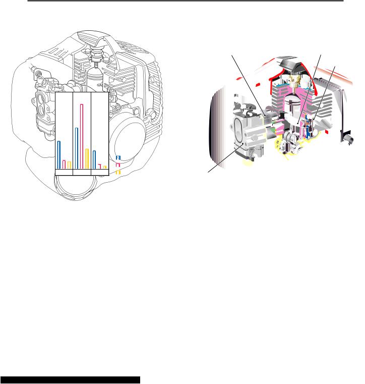
1-1 Special Features
Unlike the conventional 2-stroke engine scavenging system, the Strato-charged Engine scavenges burnt gas by the stratified lead air scavenging method. By creating a stratified air layer between burnt gas and the air-fuel mixture, this system significantly reduces exhaust of unburned air-fuel mixture.
Difference to the conventional 2-stroke engine is its very simple construction applying a new carburetor for independent intake of the air and the air-fuel mixture, an insulator, lead air intake tubes, and reed valves, etc.
 By the stratified lead air scavenging system, the Strato-charged Engine reduces unburned air-fuel mixture exhaust to about 1/3 of the conventional 2-stroke engine level.
 By optimizing the combustion chamber design, ignition plug position, and ignition timing, lean burn operation became possible.
By combining with the stratified lead air scavenging system, pollutant contained in the exhaust was reduced and fuel consumption was reduced by 30% without reducing the power.
|
|
Unit : g/HP•h (g/kwh) |
||
|
|
400 |
|
|
|
|
(544) |
|
|
|
|
280 |
|
|
|
|
(381) |
|
|
171.2 |
|
|
|
|
(232) |
|
|
|
|
|
|
139.1 |
5.3 |
|
|
|
(189) |
|
|
|
|
|
(7.2) |
|
54 |
49.5 |
|
|
|
(73) |
|
|
|
|
|
(67) |
|
1.5 |
1.0 |
|
|
|
(2.0) |
|
|
|
|
|
(1.3) |
THC + NOx |
CO |
PM |
|
|
Current Engine
Tier 2 regulation
Strato-Changed Engine
 As the catalytic converter is not applied, exhaust gas temperature increase due to the catalytic reactive heat does not occur so that the engine heat load does not increase. Therefore, same level of durability and reliability with the conventional engines are assured.
 A large size silencer and a muffler were employed and the noise level was reduced by 5 dB(A) compared to the conventional 2-stroke engines.
Insulator |
Lead Air Intake Tube (each side) |
Reed Valve (each side)
Carburetor
2

1. OUTLINE OF STRATO-CHARGED ENGINE
1-2 Principle of Operation
STRATO CHARGED ENGINE GZ25N
Major difference of the Strato-charged Engine to the conventional 2-stroke engine is that as illustrated on the following drawing, there are lead air intake tubes which are connected to the scavenging port via reed valves.
Due to crankcase depression during the piston upstroke |
As piston proceeds to downstroke after the top dead center, |
As piston proceeds to upstroke after the bottom dead center, |
|||||||||||||||||||||
(intake stroke) to the top dead centre, air-fuel mixture is charged |
a scavenging port starts to open and lead air in the scavenging |
burnt gas in the cylinder is pushed out through the exhaust |
|||||||||||||||||||||
to the crankcase and lead air is charged to the scavenging |
port moves into the cylinder earlier than the air-fuel mixture. |
port by lead air. Therefore, direct exhaust of air-fuel mixture |
|||||||||||||||||||||
ports though the reed valves. |
|
|
|
|
|
|
|
|
is almost non. |
||||||||||||||
|
|
|
|
|
|
|
|
|
|
|
|
|
|
|
|
|
|
|
|
|
|
|
Lead Air |
|
|
|
|
|
|
|
|
|
|
|
|
|
|
|
|
|
|
|
|
|
|
|
Burnt Gas |
|
|
|
|
|
|
|
|
|
|
|
|
Burnt Gas |
|
|
|
|
|
|
|
||||
|
|
|
|
|
|
|
|
|
|
|
|
|
|
|
|
|
|
|
|||||
|
|
|
|
|
|
|
|
|
Air |
Air-Fuel Mixture |
|||||||||||||
|
|
|
|
|
|
|
|
|
|
|
|
|
|
|
|
|
|||||||
Scavenging Port |
|
|
|
Reed Valve |
Air-Fuel Mixture |
|
|
|
|
Exhaust Port |
|
|
|
|
|
|
Exhaust Port |
||||||
|
|
|
|
|
|
|
|
|
|
Lead Air |
|
|
|
|
|
|
|||||||
Crankcase |
|
|
|
|
|
|
|
|
|
|
|
|
|
|
|
|
|
||||||
|
|
|
|
|
|||||||||||||||||||
|
|
|
|
|
|
|
|
|
|
|
|
|
|
|
|
|
|
|
|||||
|
|
|
|
|
|
|
|
|
|
|
|
|
|
|
|
|
|
|
|||||
|
|
|
|
|
|
|
|
|
|
|
|
|
|
|
|
|
|
|
|||||
|
|
|
|
|
|
|
|
|
|
|
|
|
|
|
|
|
|
|
|||||
|
|
|
|
|
|
|
|
|
|
|
|
Air-Fuel Mixture |
|
|
|
|
|
|
|
||||
Reed Valve Assy |
|
|
|
|
|
|
|
|
|
|
|
|
|
|
|
|
|
|
|
||||
|
|
|
|
|
|
|
|
|
|
|
|
|
|
|
|
|
|||||||
|
|
|
|
|
|
|
|
|
|
|
|
|
|
|
|
|
|
|
|
||||
Lead Air Intake Tube |
|
|
|
|
|
|
|
|
|
|
|
|
|
|
|
|
|
|
|
|
|
|
|
|
|
|
|
|
|
|
Lead Air |
|
|
|
|
|
|
|
|
|
|
|
|
|
|
|
|
|
|
|
|
|
|
|
|
|
|
|
|
|
|
|
|
|
|
|
|
|
|
|
|
|
|
|
|
|
|
|
|
|
|
|
|
|
|
|
|
|
|
|
|
|
|
|
|
|
|
|
|
|
|
|
|
|
|
|
|
|
|
|
|
|
|
|
|
|
|
|
|
|
|
|
|
|
|
|
|
|
|
|
|
|
|
|
|
|
|
|
|
|
|
|
|
|
|
|
|
|
|
|
|
|
|
|
|
|
|
|
|
|
|
|
|
|
|
|
|
|
|
|
|
|
|
|
|
|
|
|
|
|
|
|
|
|
|
|
|
|
|
|
|
|
|
|
|
|
|
|
|
|
|
|
|
|
|
|
|
|
|
|
|
|
|
|
|
Air
Scavenging Port
Air-Fuel Mixture
Carburetor
Air-Fuel Mixture
3
1. OUTLINE OF STRATO-CHARGED ENGINE
STRATO CHARGED ENGINE GZ25N
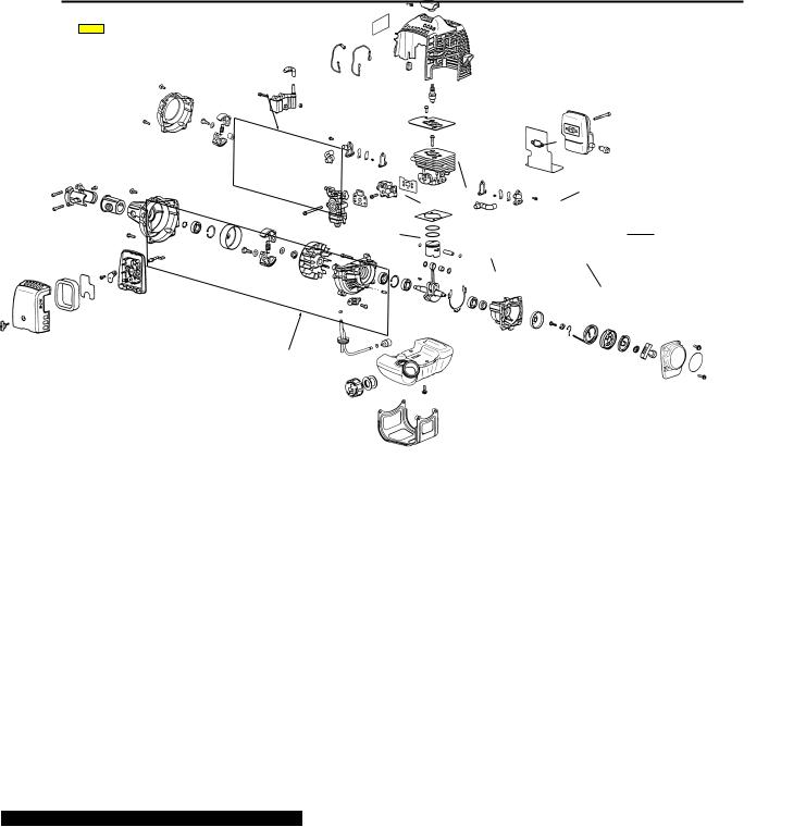
1-3 Construction (Developed Drawing)
Parts in the frames are exclusively designed for the Strato-charged Engine.
• Reciprocator SGCZ2500S
|
Spark Plug |
|
Reed Valve |
Lead Air Intake Tube |
Cylinder |
|
|
Carburetor |
Reed Valve |
|
Insulator |
|
Lead Air Intake Tube |
•Brushcutters BCZ2500S/BCZ2500SU
•Long Reach Trimmer LRTZ2500
•Short Reach Trimmer SRTZ2500
•Pole Saw PSZ2500
•Sweeper RMSZ2500
•Hand Held Edger HEZ2500S
•Split Boom Trimmer : EXZ2500S
4

2. SPECIFICATIONS AND TECHNICAL DATA
STRATO CHARGED ENGINEGZ25N
Item |
|
Unit |
Specifications |
Remarks |
||
|
|
|
|
|
|
|
Engine |
|
|
GZ25N |
|
||
|
|
|
|
|
|
|
Engine Type |
|
|
Air cooled 2-stroke single cylinder |
|
||
|
|
|
|
piston valve gasoline engine |
|
|
|
|
|
|
|
|
|
Cylinder Bore x Stroke |
mm (in.) |
ø34 x 28 (1.339 x 1.102) |
|
|||
|
|
|
|
|
|
|
Displacement |
|
cc (cu.in.) |
25.4 (1.6) |
|
||
|
|
|
|
|
|
|
Effective Compression Ratio |
|
8.0 |
|
|||
|
|
|
|
|
|
|
Fuel |
|
|
Mixture of 87 octane or above unleaded |
Use JASO FC |
||
|
|
|
|
gasoline and RedMax 2-cycle engine oil |
or ISO EDG |
|
|
|
|
|
(ratio 50 :1) or quality oil for air cooled |
grade 2-cycle |
|
|
|
|
|
2-cycle engines (ratio 32:1). |
engine oil. |
|
|
|
|
|
|
|
|
Carburetor |
|
Type |
|
Diaphragm Rotary valve |
|
|
|
|
|
|
|
|
|
|
|
Model |
|
Walbro WYA-1B |
|
|
|
|
|
|
|
|
|
Starting Method |
|
|
Recoil starter |
|
||
|
|
|
|
|
|
|
Ignition System |
|
|
CDI with automatic timing advance |
|
||
|
|
|
|
system. |
|
|
|
|
|
|
|
|
|
Ignition Timing |
|
°/ rpm |
35 / 7000 |
|
||
|
|
|
|
|
|
|
Spark Plug |
|
|
NGK CMR7A |
|
||
|
|
|
|
|
|
|
Stopping Method |
|
|
Primary coil short-circuiting |
|
||
|
|
|
|
|
|
|
Cooling System |
|
|
Forced Air Cooling |
|
||
|
|
|
|
|
|
|
Air Cleaner |
|
|
Dry Type |
|
||
|
|
|
|
|
|
|
Output Axle Rotation Direction |
|
Counterclockwise |
(View from |
|||
|
|
|
|
|
|
PTO) |
|
|
|
|
|
|
|
Clutch Type |
|
|
Automatic Centrifugal Clutch |
|
||
|
|
|
|
(Sintered Clutch Shoe) |
|
|
|
|
|
|
|
|
|
Overall Size |
|
|
Engine GZ25N for |
Engine GZ25N2 for |
|
|
|
|
|
|
exept SGCZ2500S |
SGCZ2500S |
|
|
|
|
|
|
|
|
|
|
Length |
mm (in.) |
271 (10.67) |
188 (7.40) |
|
|
|
|
|
|
|
|
|
|
Width |
mm (in.) |
223 (8.78) |
223 (8.78) |
|
|
|
|
|
|
|
|
|
|
Height |
mm (in.) |
248 9.76 |
248 9.76 |
|
|
|
|
|
|
|
|
Dry Weight |
|
kg (lbs.) |
3.1 6.8 |
2.8 6.2 |
|
|
|
|
|
|
|
|
|
Fuel tank Capacity |
|
lit. (fl,oz) |
0.65 22.0 |
|
||
|
|
|
|
|
|
|
Operating Speed |
|
rpm |
6000 |
10000 |
|
|
|
|
|
|
|
|
|
Idling Speed |
|
rpm |
3000 ±200 |
|
||
Clutch Engagement Speed |
rpm |
4000 ±200 |
|
|||
No-Load Max Speed |
rpm |
10000 |
With Standard |
|||
|
|
|
|
|
|
Head |
|
|
|
|
|
|
|
Max Output |
|
HP(kW) / rpm |
1.2 (0.9) / 7500 |
|
||
|
|
|
|
|
|
|
Max Torque |
|
kg•m(in.lbs) / rpm |
0.12 (10.4) / 6500 |
|
||
|
|
|
|
|
|
|
Full Load Fuel Consumption |
g/HP.h(g/kW.h) |
330 (449) |
|
|||
|
|
|
|
|
|
|
|
|
|
|
5 |
|
|

3. OUTLINE DRAWING
STRATO CHARGED ENGINEGZ25N
Unit : mm (in.)
Carburetor
Air Cleane
|
Fuel Cap |
|
Fuel Tank |
|
122 (4.80) |
|
223 (8.78) |
Plug Cap |
|
|
Fan Cover |
Fan Cover |
Recoil Starter |
|
|
|
) |
|
9.76 |
|
( |
|
248 |
|
) |
|
4.45 |
|
( |
|
113 |
168 (6.61) |
7.85 |
(0.31) |
238(9.36)
271 (10.67)
GZ25N for
BCZ2500S, BCZ2500SU,
LRTZ2500, SRTZ2500,
PSZ2500, RMSZ2500,
HEZ2500S and EXZ2500S.
Engine Cover
Muffler
Tank Guard
248 (9.76)
113 (4.45)
85 (3.35)
155(6.10) 188 (7.40)
GZ25N2 for
SGCZ2500S.
6

4. MAINTENANCE SPECIFICATIONS
4-1 Engine Block
STRATO CHARGED ENGINEGZ25N
Maintenance Item |
|
|
Standard |
Limit |
Measuring |
Remarks |
||||
|
|
Instrument |
||||||||
|
|
|
|
|
|
|
|
|
|
|
|
|
|
|
|
|
|
|
|
|
|
Cylinder |
|
|
|
|
|
|
|
|
|
|
|
|
|
|
|
|
|
|
|
|
|
|
Compression |
|
|
|
|
8.7(124) |
5.5(78) |
Compression |
|
|
|
kg/cm2 (psi) |
|
|
|
Gauge |
|
||||
|
Bore |
|
|
|
|
|
ø 34(1.339) |
Peel off of plating or |
Cylinder |
|
|
mm(in.) |
|
|
|
|
expose of base met |
Gauge |
|
||
|
|
|
|
|
|
|
||||
|
|
|
|
|
|
|
|
|
|
|
Piston |
|
|
|
|
|
|
|
|
|
|
|
|
|
|
|
|
|
|
|
|
|
|
Piston dia. |
|
|
|
|
ø33.96(1.3370) |
ø33.86(1.3331) |
Micrometer |
At right angle to |
|
|
mm(in.) |
|
|
|
|
ø33.975(1.3376) |
piston pin. |
|||
|
|
|
|
|
|
|
||||
|
|
|
|
|
|
|
||||
|
Piston Ring Groove Width mm(in.) |
|
1.2(0.047) |
1.3(0.051) |
Thickness Gauge |
|
||||
|
|
|
|
|
|
|
|
|||
|
Piston Pin Hole Bore |
mm(in.) |
|
ø8(0.3150) |
ø8.04(0.3165) |
Cylinder Gauge |
|
|||
|
|
|
|
|
|
|
||||
|
Clearance between |
|
0.025(0.0010) |
0.15(0.0059) |
Micrometer / |
|
||||
|
Piston & Cylinder |
mm(in.) |
|
0.065(0.0026) |
Cylinder Gauge |
|
||||
|
|
|
|
|||||||
|
|
|
|
|
|
|||||
|
Clearance between Groove |
0.04 (0.0016) |
0.1(0.0039) |
Thickness |
|
|||||
|
and Piston Ring |
mm(in.) |
|
0.08(0.0031) |
Gauge |
|
||||
|
|
|
|
|||||||
|
|
|
|
|
|
|||||
|
Fitting between Piston Pin & |
0.005T(0.00020T) |
0.05L(0.0020L) |
Micrometer / |
|
|||||
|
Piston Pin Hole |
mm(in.) |
|
0.011L(0.00043L) |
Cylinder Gauge |
|
||||
|
|
|
|
|||||||
|
|
|
|
|
|
|
|
|
|
|
Piston Ring |
|
|
|
|
|
|
|
|
|
|
|
|
|
|
|
|
|
|
|||
|
End Gap |
mm(in.) |
|
0.1(0.0038) |
0.5(0.0197) |
Thickness Gauge |
Measure at |
|||
|
|
|
|
|
|
|
0.3(0.0118 |
cylinder skirt. |
||
|
|
|
|
|
|
|
|
|
||
|
|
|
|
|
|
|
|
|||
|
Width mm(in.) |
|
|
1.2(0.0472) |
1.1(0.0433) |
Micrometer |
|
|||
|
|
|
|
|
|
|
|
|
|
|
Piston Pin |
|
|
|
|
|
|
|
|
|
|
|
|
|
|
|
|
|
|
|
||
|
Diameter |
mm(in.) |
|
|
ø8(0.315) |
ø7.98(0.314) |
Micrometer |
No stepwear is allowed |
||
Connecting Rod |
|
|
|
|
|
|
|
|
|
|
|
|
|
|
|
|
|
|
|||
|
Small End Bore |
mm(in.) |
|
ø11 (0.433) |
ø11.05(0.435) |
Cylinder Gauge |
|
|||
|
|
|
|
|
|
|
||||
|
Clearance between Small End Piston |
0 |
0.021(0.0008) |
0.045(0.0018) |
Micrometer / |
|
||||
|
Pin & Needle Bearing |
mm(in.) |
Cylinder Gauge |
|
||||||
|
|
|
|
|
||||||
|
|
|
|
|
|
|||||
|
Clearance between Large End Crank |
0.005(0.0002) |
0.05(0.0020) |
Micrometer / |
|
|||||
|
Pin & Needle Bearing |
mm(in.) |
0.028(0.0011) |
Cylinder Gauge |
|
|||||
|
|
|
||||||||
|
|
|
|
|
|
|
||||
|
Parallelness of Large/Small |
|
– |
0.15/100 |
Mandrel |
|
||||
|
End Bores |
|
mm(in.) |
|
|
Dial Gauge |
|
|||
|
|
|
|
|
|
|
||||
|
|
|
|
|
|
|
|
|
|
|
Crankshaft |
|
|
|
|
|
|
|
|
|
|
|
|
|
|
|
|
|
||||
|
Diameter at Main Bearing |
ø12(0.4724) |
ø11.97(0.4713) |
Micrometer |
|
|||||
|
(MAG, PTO) |
mm(in.) |
|
|||||||
|
|
|
|
|
|
|||||
|
|
|
|
|
|
|
||||
|
Diameter at Oil Seal |
|
ø12(0.472) |
ø11.09(0.469) |
Micrometer |
|
||||
|
(MAG, PTO) |
mm(in.) |
|
|
||||||
|
|
|
|
|
|
|||||
|
|
|
|
|
|
|
||||
|
Diameter at Clutch Drum |
ø12(0.4724) |
ø11.97(0.4713) |
Micrometer |
|
|||||
|
Bearing ( PTO) |
mm(in.) |
|
|||||||
|
|
|
|
|
|
|||||
|
|
|
|
|
|
|
|
|||
|
Eccentricity |
mm(in.) |
|
– |
0.07(0.028) |
Dial Gauge / |
Adjust or exchange |
|||
|
|
|
|
|
|
|
Centre Support |
|||
|
|
|
|
|
|
|
|
|||
|
Width between crank webs |
mm(in.) |
|
22 |
21.9 22.1 |
Micrometer |
|
|||
|
|
|
|
|
|
|
|
|
||
|
Axial Play |
mm(in.) |
|
|
– |
0.5(0.020) |
Thickness Gauge |
|
||
|
|
|
|
|
|
|
||||
|
Main Bearing (Ball Bearing) |
|
– |
Flutter, irregular |
|
|
||||
|
|
|
|
|
|
|
noise generated |
|
|
|
|
|
|
|
|
|
|
|
|
|
|
|
|
|
|
|
|
|
|
|
|
|
Clutch Drum |
|
|
|
|
|
|
|
|
|
|
|
|
|
|
|
|
|
||||
|
Bore at Bearing |
mm(in.) |
ø12 (0.472) |
ø12.05(0.474) |
Cylinder Gauge |
|
||||
|
|
|
|
|
|
|
|
|||
|
Bore at Drum |
mm(in.) |
|
ø54(2.126) |
ø54.6(2.150) |
Vernia Calipers |
|
|||
|
|
|
|
|
|
|
|
|
|
|
7
 Loading...