


RTL8111
INTEGRATED GIGABIT ETHERNET CONTROLLER
FOR PCI EXPRESS™ APPLICATIONS
DATASHEET
Rev. 1.2
24 March 2005
Track ID: JATR-1076-21
RTL8111
Datasheet
COPYRIGHT
©2005 Realtek Semiconductor Corp. All rights reserved. No part of this document may be reproduced,
transmitted, transcribed, stored in a retrieval system, or translated into any language in any form or by any
means without the written permission of Realtek Semiconductor Corp.
DISCLAIMER
Realtek provides this document “as is”, without warranty of any kind, neither expressed nor implied,
including, but not limited to, the particular purpose. Realtek may make improvements and/or changes in
this document or in the product described in this document at any time. This document could include
technical inaccuracies or typographical errors.
TRADEMARKS
Realtek is a trademark of Realtek Semiconductor Corporation. Other names mentioned in this document
are trademarks/registered trademarks of their respective owners.
USING THIS DOCUMENT
This document is intended for the software engineer’s reference and provides detailed programming
information.
Though every effort has been made to ensure that this document is current and accurate, more information
may have become available subsequent to the production of this guide. In that event, please contact your
Realtek representative for additional information that may help in the development process.
REVISION HISTORY
Revision Release Date
1.0 2004/08/19 First release.
1.1 2004/11/05 Package changes. See section 8, Mechanical Dimensions, page 23, and
1.2 2005/03/24 Changed Table 8, Power & Ground, page 6.
Summary
section 9, Ordering Information, page 24.
Changed Table 6, Regulator & Reference, page 5.
Added lead (Pb)-free package identification information on page 3 and on
page 24.
Integrated Gigabit Ethernet Controller for PCI Express ii Track ID: JATR-1076-21 Rev. 1.2

TL8111
Datasheet
Table of Contents
1. GENERAL DESCRIPTION...............................................................................................................1
2. FEATURES ..........................................................................................................................................2
3. SYSTEM APPLICATIONS................................................................................................................2
4. PIN ASSIGNMENTS ..........................................................................................................................3
4.1. LEAD (PB)-FREE PACKAGE IDENTIFICATION ..................................................................................3
5. PIN DESCRIPTIONS .........................................................................................................................4
5.1. POWER MANAGEMENT/ISOLATION .................................................................................................4
5.2. PCI EXPRESS INTERFACE................................................................................................................4
5.3. EEPROM .......................................................................................................................................4
5.4. TRANSCEIVER INTERFACE...............................................................................................................5
5.5. CLOCK ............................................................................................................................................5
5.6. REGULATOR & REFERENCE ............................................................................................................5
5.7. LEDS..............................................................................................................................................6
5.8. POWER & GROUND.........................................................................................................................6
5.9. NC (NOT CONNECTED) PINS ..........................................................................................................6
6. FUNCTIONAL DESCRIPTION........................................................................................................7
6.1. PCI EXPRESS BUS INTERFACE ........................................................................................................7
6.1.1. PCI Express Transmitter .......................................................................................................7
6.1.2. PCI Express Receiver ............................................................................................................7
6.2. LED FUNCTIONS ............................................................................................................................7
6.2.1. Link Monitor ..........................................................................................................................7
6.2.2. Rx LED...................................................................................................................................8
6.2.3. Tx LED...................................................................................................................................8
6.2.4. Tx/Rx LED .............................................................................................................................9
6.2.5. LINK/ACT LED ...................................................................................................................10
6.3. PHY TRANSCEIVER ......................................................................................................................11
6.3.1. PHY Transmitter..................................................................................................................11
6.3.2. PHY Receiver.......................................................................................................................11
6.4. NEXT PAGE...................................................................................................................................12
6.5. EEPROM INTERFACE ..................................................................................................................12
6.6. POWER MANAGEMENT .................................................................................................................13
6.7. VITAL PRODUCT DATA (VPD)......................................................................................................15
7. CHARACTERISTICS ......................................................................................................................16
7.1. ABSOLUTE MAXIMUM RATINGS ...................................................................................................16
7.2. RECOMMENDED OPERATING CONDITIONS ....................................................................................16
7.3. CRYSTAL REQUIREMENTS.............................................................................................................16
7.4. THERMAL CHARACTERISTICS .......................................................................................................17
7.5. DC CHARACTERISTICS .................................................................................................................17
Integrated Gigabit Ethernet Controller for PCI Express iii Track ID: JATR-1076-21 Rev. 1.2

RTL8111
Datasheet
7.6. AC CHARACTERISTICS .................................................................................................................18
7.6.1. Serial EEPROM Interface Timing .......................................................................................18
7.7. PCI EXPRESS BUS PARAMETERS ..................................................................................................19
7.7.1. Differential Transmitter Parameters ...................................................................................19
7.7.2. Differential Receiver Parameters........................................................................................20
7.7.3. REFCLK Parameters...........................................................................................................20
7.7.4. Auxiliary Signal Timing Parameters ...................................................................................22
8. MECHANICAL DIMENSIONS ......................................................................................................23
8.1. MECHANICAL DIMENSIONS NOTES ...............................................................................................24
9. ORDERING INFORMATION.........................................................................................................24
Integrated Gigabit Ethernet Controller for PCI Express iv Track ID: JATR-1076-21 Rev. 1.2

RTL8111
Datasheet
List of Tables
Table 1. Power Management/Isolation......................................................................................................4
Table 2. PCI Express Interface..................................................................................................................4
Table 3. EEPROM.....................................................................................................................................4
Table 4. Transceiver Interface...................................................................................................................5
Table 5. Clock ...........................................................................................................................................5
Table 6. Regulator & Reference................................................................................................................5
Table 7. LEDs............................................................................................................................................6
Table 8. Power & Ground .........................................................................................................................6
Table 9. NC (Not Connected) Pins............................................................................................................6
Table 10. EEPROM Interface ...................................................................................................................12
Table 11. Absolute Maximum Ratings .....................................................................................................16
Table 12. Recommended Operating Conditions.......................................................................................16
Table 13. Crystal Requirements................................................................................................................16
Table 14. Thermal Characteristics ............................................................................................................17
Table 15. DC Characteristics ....................................................................................................................17
Table 16. EEPROM Access Timing Parameters.......................................................................................18
Table 17. Differential Transmitter Parameters..........................................................................................19
Table 18. Differential Receiver Parameters ..............................................................................................20
Table 19. REFCLK Parameters.................................................................................................................20
Table 20. Auxiliary Signal Timing Parameters.........................................................................................22
Table 21. Ordering Information ................................................................................................................24
List of Figures
Figure 1. Pin Assignments.........................................................................................................................3
Figure 2. Rx LED ......................................................................................................................................8
Figure 3. Tx LED ......................................................................................................................................8
Figure 4. Tx/Rx LED.................................................................................................................................9
Figure 5. LINK/ACT LED ......................................................................................................................10
Figure 6. Serial EEPROM Interface Timing ...........................................................................................18
Figure 7. REFCLK Single-Ended Measurement Points for T
Figure 8. REFCLK Single-Ended Measurement Points for V
Figure 9. REFCLK Differential Measurement Points for T
Figure 10. REFCLK V
Range .............................................................................................................22
cross
Figure 11. Auxiliary Signal Timing..........................................................................................................22
Integrated Gigabit Ethernet Controller for PCI Express v Track ID: JATR-1076-21 Rev. 1.2
and T
rise
, V
ovs
, Duty Cycle, and Jitter........................21
period
...............................................21
fall
and Vrb......................................21
uds,

TL8111
Datasheet
1. General Description
The Realtek RTL8111 Gigabit Ethernet controller combines a triple-speed IEEE 802.3 compliant Media
Access Controller (MAC) with a triple-speed Ethernet transceiver, PCI Express bus controller, and
embedded memory. With state-of-the-art DSP technology and mixed-mode signal technology, they offer
high-speed transmission over CAT 5 UTP cable or CAT 3 UTP (10Mbps only) cable. Functions such as
Crossover Detection & Auto-Correction, polarity correction, adaptive equalization, cross-talk cancellation,
echo cancellation, timing recovery, and error correction are implemented to provide robust transmission
and reception capability at high speeds.
The device supports the PCI Express 1.0a bus interface for host communications with power management
and is compliant with the IEEE 802.3u specification for 10/100Mbps Ethernet and the IEEE 802.3ab
specification for 1000Mbps Ethernet. It also supports an auxiliary power auto-detect function, and will
auto-configure related bits of the PCI power management registers in PCI configuration space.
Advanced Configuration Power management Interface (ACPI)--power management for modern operating
systems that are capable of Operating System-directed Power Management (OSPM)—is also supported to
achieve the most efficient power management possible. PCI Message Signaled Interrupt (MSI) is also
supported.
In addition to the ACPI feature, remote wake-up (including AMD Magic Packet™, Re-LinkOk, and
Microsoft® Wake-up frame) is supported in both ACPI and APM (Advanced Power Management)
environments. To support WOL from a deep power down state (e.g., D3cold, i.e. main power is off and
only auxiliary exists), the auxiliary power source must be able to provide the needed power for the
RTL8111.
The RTL8111 is fully compliant with Microsoft® NDIS5 (IP, TCP, UDP) Checksum and Segmentation
Task-offload features, and supports IEEE 802 IP Layer 2 priority encoding and 802.1Q Virtual bridged
Local Area Network (VLAN). The above features contribute to lowering CPU utilization, especially
benefiting performance when in operation on a network server.
The device features next-generation PCI Express interconnect technology. PCI Express is a
high-bandwidth, low pin count, serial, interconnect technology that offers significant improvements in
performance over conventional PCI and also maintains software compatibility with existing PCI
infrastructure.
The RTL8111 is suitable for multiple market segments and emerging applications, such as desktop, mobile,
workstation, server, communications platforms, and embedded applications.
Integrated Gigabit Ethernet Controller for PCI Express 1 Track ID: JATR-1076-21 Rev. 1.2

2. Features
RTL8111
Datasheet
Integrated 10/100/1000 transceiver
Auto-Negotiation with Next Page
capability
Supports PCI Express™ 1.0a
Supports pair swap/polarity/skew
correction
Crossover Detection & Auto-Correction
Wake-on-LAN and remote wake-up
support
Microsoft® NDIS5 Checksum Offload
(IP, TCP, UDP) and Largesend Offload
support
Supports Full Duplex flow control
(IEEE 802.3x)
Fully compliant with IEEE 802.3,
IEEE 802.3u, IEEE 802.3ab
Supports IEEE 802.1P Layer 2 Priority
Encoding
Supports IEEE 802.1Q VLAN tagging
Serial EEPROM
Transmit/Receive on-chip buffer
(8KB/16KB) support
Supports power down/link down power
saving
Supports PCI Message Signaled
Interrupt (MSI)
128-pin DHS-QFP package
3. System Applications
PCI Express™ Gigabit Ethernet on Motherboard, Notebook, or Embedded system
Integrated Gigabit Ethernet Controller for PCI Express 2 Track ID: JATR-1076-21 Rev. 1.2
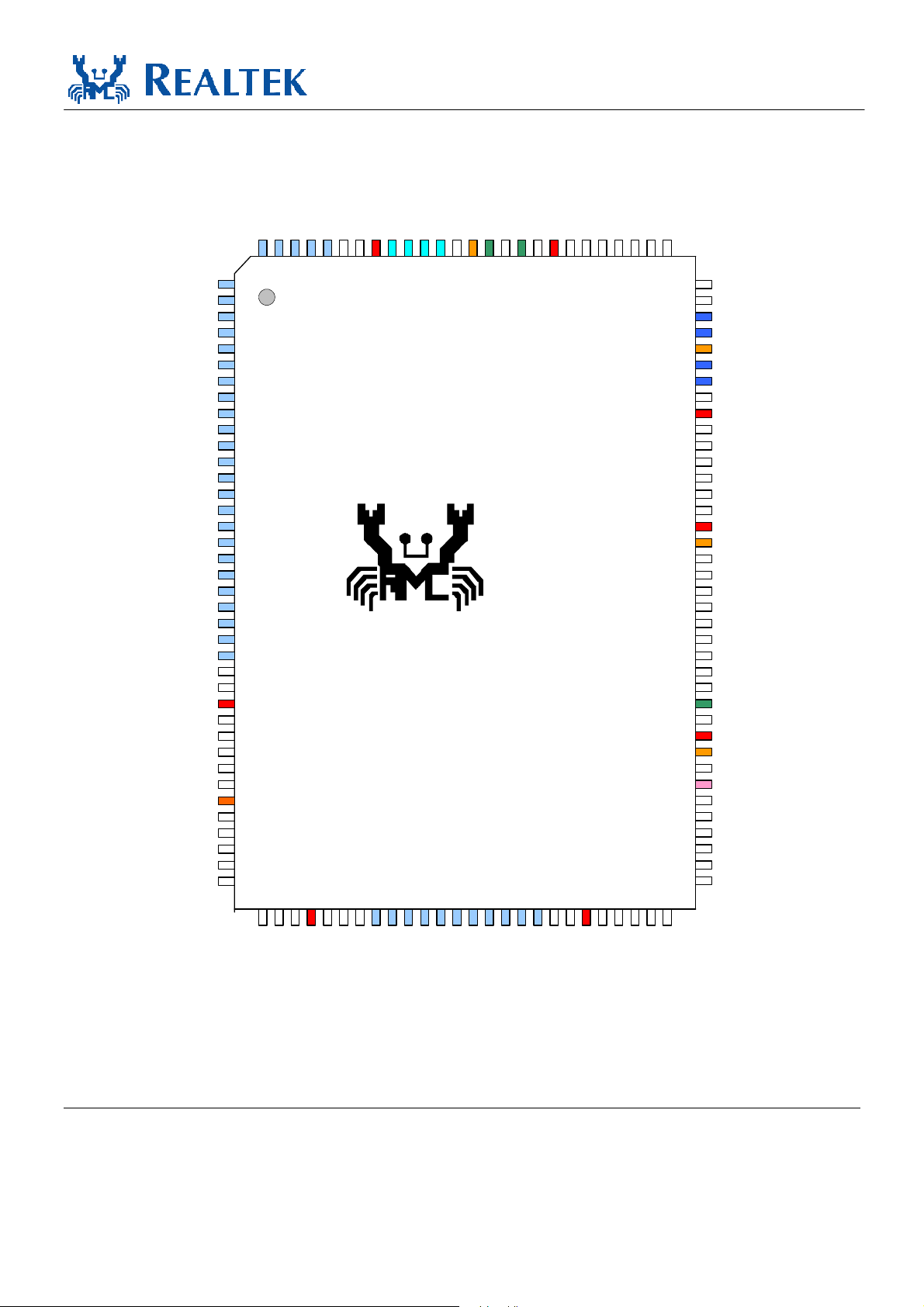
4. Pin Assignments
CKXTAL2
CKXTAL1
GVDD21
GND
AVDD33
VDD18
GND
LED0
GND
LED1
LED2
LED3
NC
TL8111
Datasheet
VDD33
NC
NC
NC
NC
VDD18
GND
NCNCNCNCNC
NC
VCTRL18
GND
RSET
GND
MDIP0
MDIN0
AVDD25
GND
MDIP1
MDIN1
AVDD25
VCTRL25
GND
AVDD33
VCTRL20
GVDD21
GND
MDIP2
MDIN2
AVDD25
GND
MDIP3
MDIN3
AVDD25
GND
GND
VDD18
NC
NC
NC
NC
NC
VDD33
NC
NC
LANWAKEB
PERSTB
GND
108
107
126
125
123
128
127
1
2
3
4
5
6
7
8
9
1
0
11
12
13
14
15
16
17
18
19
20
21
22
23
24
25
26
27
28
29
30
31
32
33
34
35
36
37
38
40
39
124
44
43
42
41
120
122
121
LLLLLLL TXXXV
51
50
49
48
47
46
45
53
52
RTL8111
57
56
55
54
58
109
110
111
112
113
114
115
116
117
118
119
106
61
60
59
103
105
104
102
101
100
63
62
64
NC
GND
EESK
EEDI
99
VDD33
98
EEDO
97
EECS
96
NC
95
94
VDD18
93
GND
92
GND
91
NC
NC
90
NC
89
NC
88
87
VDD18
NC
86
GND
85
NC
84
NC
83
NC
82
NC
81
GND
80
NC
79
NC
78
77
NC
76
NC
75
NC
74
VDD18
73
VDD33
72
GND
ISOLATEB
71
NC
70
NC
69
NC
68
NC
67
NC
66
NC
65
EGND
NCNCNC
NC
NC
EVDD18
HSIP
HSIN
EGND
VDD18
NC
EVDD18
EVDD18
REFCLK_P
REFCLK_M
HSOP
HSON
GND
VDD18
NC
NC
NC
NC
NC
NC
Figure 1. Pin Assignments
4.1. Lead (Pb)-Free Package Identification
Lead (Pb)-free package is indicated by an “L” in the location marked “T” in Figure 1.
Integrated Gigabit Ethernet Controller for PCI Express 3 Track ID: JATR-1076-21 Rev. 1.2
5. Pin Descriptions
The signal type codes below are used in the following tables:
I: Input S/T/S: Sustained Tri-State
O: Output O/D: Open Drain
T/S: Tri-State bi-directional input/output pin
5.1. Power Management/Isolation
Table 1. Power Management/Isolation
Symbol Type Pin No Description
LANWAKEB O/D 36
ISOLATEB I 71
Power Management Event: Open drain, active low.
Used to reactivate the PCI Express slot’s main power rails and reference clocks.
Isolate Pin: Active low.
Used to isolate the RTL8111 from the PCI Express bus. The RTL8111 will not drive
its PCI Express outputs (excluding LANWAKEB) and will not sample its PCI
Express input as long as the Isolate pin is asserted.
TL8111
Datasheet
5.2. PCI Express Interface
Table 2. PCI Express Interface
Symbol Type Pin No Description
REFCLK_P I 50
REFCLK_N I 51
HSOP O 54
HSON O 55
HSIP I 47
HSIN I 48
PERSTB I 37
PCI Express Differential Reference Clock Source: 100MHz ± 300ppm.
PCI Express Transmit Differential Pair.
PCI Express Receive Differential Pair.
PCI Express Reset Signal: Active low.
When the PERSTB is asserted at power-on state, the RTL8111 returns to a
pre-defined reset state and is ready for initialization and configuration after
the de-assertion of the PERSTB.
5.3. EEPROM
Table 3. EEPROM
Symbol Type Pin No Description
EESK O 75 Serial data clock.
EEDI: Output to serial data input pin of EEPROM.
AUX: Input pin to detect if Aux. Power exists or not on initial power-on.
EEDI/AUX O/I 74
EEDO I 72 Input from serial data output pin of EEPROM.
EECS O 71 EECS: EEPROM chip select.
This pin should be connected to EEPROM. To support wakeup from ACPI
D3cold or APM power-down, this pin must be pulled high to Aux. Power
via a resistor. If this pin is not pulled high to Aux. Power, the RTL8111
assumes that no Aux. Power exists.
Integrated Gigabit Ethernet Controller for PCI Express 4 Track ID: JATR-1076-21 Rev. 1.2
 Loading...