

Realtek RTL8100 Programming Manual

RTL8100
REALTEK SINGLE CHIP
FAST ETHERNET CONTROLLER
WITH POWER MANAGEMENT
RTL8100
PROGRAMMING GUIDE
1 Packet Transmission ................................................................................................................................................................ 2
1.1 Architecture........................................................................................................................................................................ 2
1.2 Transmit Descriptors.......................................................................................................................................................... 2
1.3 The Transmission Process .................................................................................................................................................. 3
1.4 Registers Involved.............................................................................................................................................................. 4
1.5 Software Issues................................................................................................................................................................... 4
1.7 Sample code ....................................................................................................................................................................... 5
2 Packet Reception...................................................................................................................................................................... 6
2.1 Architecture........................................................................................................................................................................ 6
2.2 The Packet Header ............................................................................................................................................................. 7
2.3 The Transmission Process .................................................................................................................................................. 7
2.4 Registers Involved.............................................................................................................................................................. 7
2.5 Software Issues................................................................................................................................................................... 8
2.6 Configuration ..................................................................................................................................................................... 8
2.7 Sample Code ...................................................................................................................................................................... 9
3 Initialization............................................................................................................................................................................ 10
Additional Notes........................................................................................................................................................................ 10
This document is intended for use by the software engineer when programming for the Realtek RTL8100 series NIC controller
chips. Information pertaining to the hardware design of products using these chips is contained in a separate document.
Though every effort has been made to assure that this document is current and accurate, more information may have become
available subsequent to the production of this programming guide. In that event, please contact your Realtek representative for
additional information which can help in the development process.
2001/12/10 Rev.1.0
1

RTL8100
1 Packet Transmission
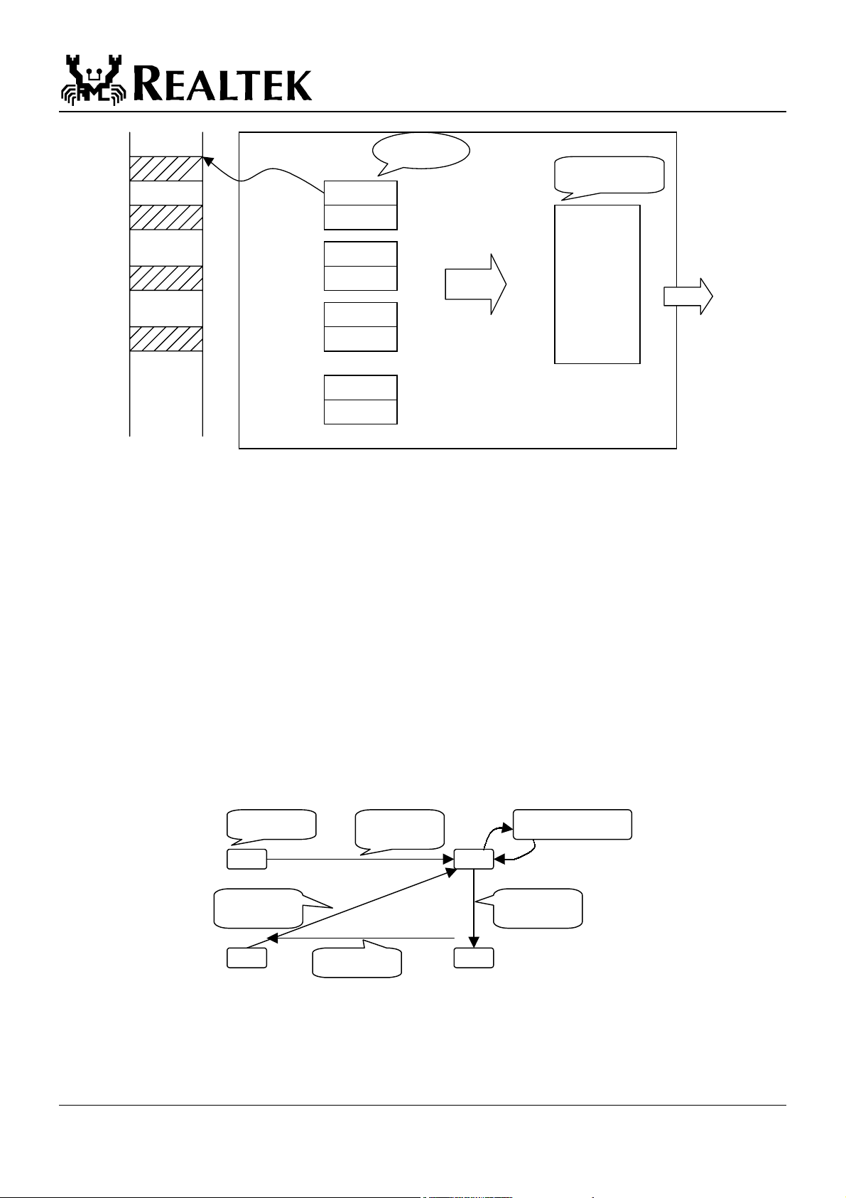
1.1 Architecture
The transmit path of the RTL8100 uses 4 descriptors, each descriptor with a fixed IO address offset. The 4 descriptors are used in
a round-robin fashion. As a descriptor is written, PCI operations start and move packets in the memory which the descriptor
specifies to the Transmit FIFO. The transmit FIFO is a 2k byte buffer in the chip which holds the data which will be moved to the
line (cable). Data in the Transmit FIFO starts to move to the line when the early transmit threshold is met. The early transmit
threshold is also specified in the descriptor.
1.2 Transmit Descriptors
A transmit descriptor consist of 2 registers, which are specified below.
Register 1: Transmit Start Address (TSAD0-3) register. The physical address of each packet (Note: the packet must be in a
continuous physical memory)
Register 2: Transmit Status (TSD0-3) register. A detailed description of this register is listed below.
Bit R/W Symbol Description
31 R CRS Carrier Sense Lost: This bit is set to 1 when the carrier is lost during
transmission of a packet.
30 R TABT Transmit Abort: This bit is set to 1 if the transmission of a packet was
aborted. This bit is read only, writing to this bit is not affected.
29 R OWC Out of Window Collision: This bit is set to 1 if the RTL8100 encountered an
"out of window" collision during the transmission of a packet.
28 R CDH CD Heart Beat: The same as RTL8029(AS).
This bit is cleared in the 100Mbps mode.
27-24 R NCC3-0 Number of Collision Count: Indicates the number of collisions
encountered during the transmission of a packet.
23-22 - 21-16 R/W ERTXTH5-0 Early Tx Threshold: Specifies the threshold level in the Tx FIFO to begin
15 R TOK Tr a n s m i t O K : Set to 1 indicates that the transmission of a packet was
14 R TUN Transmit FIFO Underrun: Set to 1 if the Tx FIFO was exhausted during
13 R/W OWN OWN: The RTL8100 sets this bit to 1 when the Tx DMA operation of this
12-0 R/W SIZE Descriptor Size: The total size in bytes of the data in this descriptor. If the
Reserved
the transmission. When the byte count of the data in the Tx FIFO reaches
this level, (or the FIFO contains at least one complete packet) the RTL8100
will transmit this packet.
000000 = 8 bytes
These fields count from 000001 to 111111 in unit of 32 bytes.
This threshold must be avoided from exceeding 2K byte.
completed successfully and no transmit underrun occurs.
the transmission of a packet. The RTL8100 can re-transfer data if the Tx
FIFO underruns and can also transmit the packet to the wire successfully
even though the Tx FIFO underruns. That is, when TSD<TUN>=1,
TSD<TOK>=0 and ISR<TOK>=1 (or ISR<TER>=1).
descriptor was completed. The driver must set this bit to 0 when the
Transmit Byte Count (bit0-12) is written. The default value is 1.
packet length is more than 1792 byte (0700h), the Tx queue will be invalid,
i.e. the next descriptor will be written only after the OWN bit of that long
packet's descriptor has been set.
2001/12/10 Rev.1.0
2
RTL8100
p
Descriptor
0
Tx FIFO
TSAD0
TSD0
TSAD1
TSD1
TSAD2
TSD2
TSAD3
TSD3
1.3 The Transmission Process
The following process describes the transmission of a packet.
1. The packet is copied to a physically continuous buffer in memory.
2. The appropriate descriptor is written as follows.
a. Enter the physical address of this buffer into the Start Address register.
b. Enter the size of this packet, and the early transmit threshold into the Transmit Status register. Also,
clear the OWN bit in TSD. This starts the PCI operation.
3. As the data moved into the FIFO meets the early transmit threshold, the chip starts to move data from the FIFO to the
line.
4. When the whole packet is moved to the FIFO, the OWN bit is set to 1.
5. When the whole packet is moved to the line, the TOK (in TSD) is set to 1.
6. If TOK (IMR) is set to 1 and TOK (ISR) is set, then an interrupt is triggered.
7. When an interrupt service routine is called, the driver should clear TOK (ISR) State Diagram: (TOK,OWN)
Initial
0,1 0,0
Driver clears
Own bit
Start PCI operation
Own: 1->0
Transmit Underrun
Finish PCI operation
Own: 0->1
Finish send
acket
0,1 1,1
2001/12/10 Rev.1.0
3
 Loading...