

Page 1

LCD Television
User’s Guide
Changing Entertainment. Again.
Page 2
Important Information
CAUTION
RISK OF ELECTRIC
SHOCK DO NOT OPEN
Caution: To reduce the risk of electric shock, do not
remove cover (or back). No user serviceable parts
inside. Refer servicing to qualified service personnel.
WARNING
To reduce the risk of fire or electric
shock, do not expose this product
to rain or moisture.
The apparatus shall not be exposed
to dripping or splashing and that
no objects filled with liquids, such
as vases, shall be placed on the
apparatus.
Refer to the identification/rating label located on the back panel of your
product for its proper operating voltage.
FCC Regulations state that unauthorized changes or modifications to this
equipment may void the user’s authority to operate it.
Cable TV Installer: This reminder is provided to call your attention to Article
820-40 of the National Electrical Code (Section 54 of the Canadian Electrical
Code, Part 1) which provides guidelines for proper grounding and, in
particular, specifies that the cable ground shall be connected to the grounding
system of the building as close to the point of cable entry as practical.
This symbol indicates important instructions
accompanying the product.
This symbol indicates "dangerous voltage"
inside the product that presents a risk of
electric shock or personal injury.
Product Registration
Please fill out the product registration card (packed separately) and return it immediately. For U.S. customers: Your RCA
Consumer Electronics product may also be registered at www.rca.com/productregistration. Registering this product
allows us to contact you if needed.
Product Information
Keep your sales receipt to obtain warranty parts and service and for proof of purchase. Attach it here and record the
serial and model numbers. These numbers are located on the product.
Model No. ____________________ Serial No. __________________ Purchase Date: ______________
Dealer/Address/Phone: _________________________________________________________________________
Page 3
Important Information
Important Safety Instructions
1. Read these instructions.
2. Keep these instructions.
3. Heed all warnings.
4. Follow all instructions.
5. Do not use this apparatus near water.
6. Clean only with dry cloth.
7. Do not block any ventilation openings. Install in accordance with the manufacturer’s
instructions.
8. Do not install near any heat sources such as radiators, heat registers, stoves, or other
apparatus (including amplifiers) that produce heat.
9. Do not defeat the safety purpose of the polarized or grounding-type plug. A polarized plug
has two blades with one wider than the other. A grounding type plug has two blades and a
third grounding prong. The wide blade or the third prong is provided for your safety. If the
provided plug does not fit into your outlet, consult an electrician for replacement of the
obsolete outlet.
10. Protect the power cord from being walked on or pinched particularly at plugs, convenience
receptacles, and the point where they exit from the apparatus.
11. Only use attachments/accessories specified by the manufacturer.
12. Use only with the cart, stand, tripod, bracket, or table specified by the manufacturer, or sold with the apparatus. When a cart is used, use caution when moving
the cart/apparatus combination to avoid injury from tip-over.
13. Unplug this apparatus during lightning storms or when unused for long periods of time.
14. Refer all servicing to qualified service personnel. Servicing is required when the apparatus
has been damaged in any way, such as power-supply cord or plug is damaged, liquid has
been spilled or objects have fallen into the apparatus, the apparatus has been exposed to
rain or moisture, does not operate normally, or has been dropped.
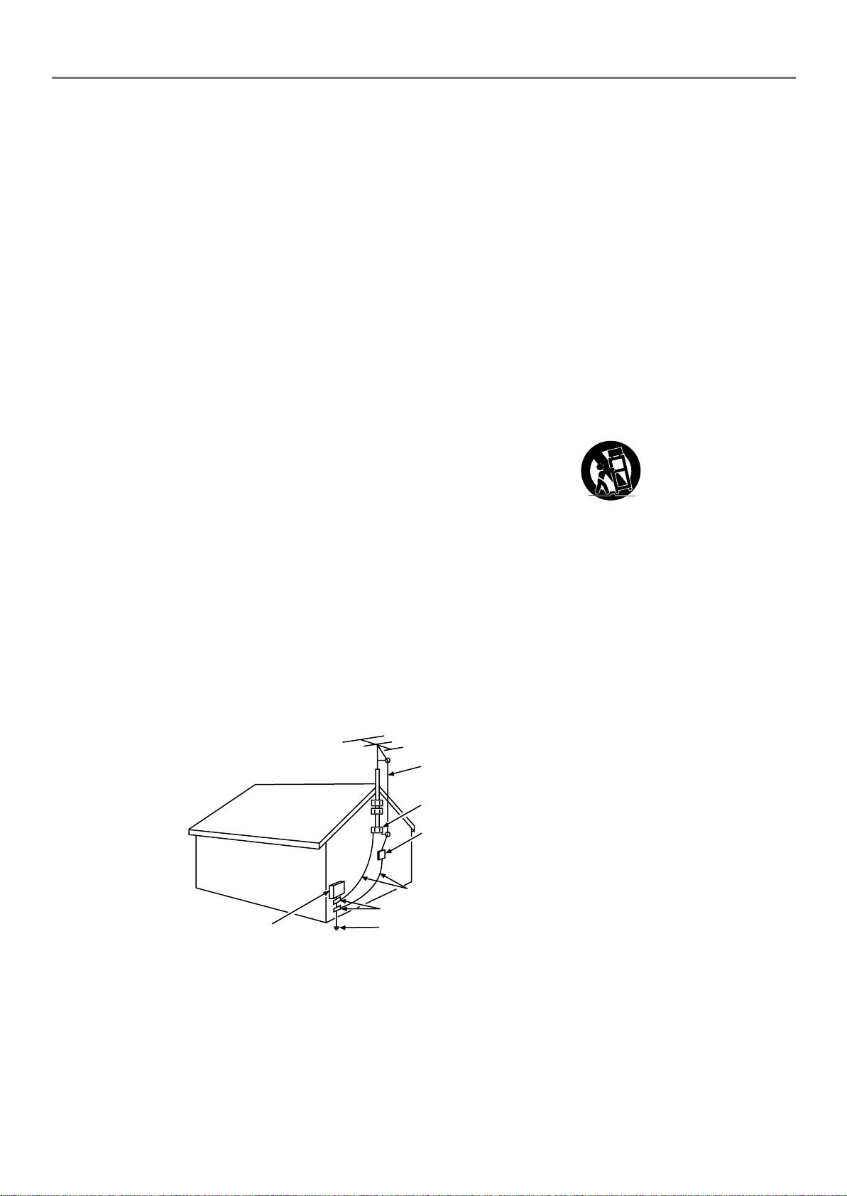
15. If an outside antenna or cable system is connected to the product, be sure the antenna or
cable system is grounded so as to provide some protection against voltage surges and builtup static charges. Section 810 of the National Electrical Code, ANSI/NFPA No. 70-1984
(Section 54 of Canadian Electrical Code, Part 1) provides information with respect to proper
grounding of the mast and supporting structure, grounding of the lead-in wire to an
antenna-discharge unit, size of grounding conductors, location of antenna-discharge unit,
connection to grounding electrodes, and requirements for the grounding electrode. See
following example.
ELECTRIC SERVICE
EQUIPMENT
ANTENNA
LEAD IN
WIRE
GROUND CLAMP
ANTENNA
DISCHARGE UNIT
(NEC SECTION 810-20)
GROUNDING CONDUCTORS
(NEC SECTION 810-21)
GROUND CLAMPS
POWER SERVICE GROUNDING
ELECTRODE SYSTEM
(NEC ART 250, PART H)
i
Page 4

This page left intentionally blank.
Page 5

Table of Contents
Chapter 1: Connections & Setup
Things to Consider Before You Connect ........................................................................................ 3
Protect Against Power Surges.................................................................................................. 3
Protect Components from Overheating.................................................................................. 3
Important Stand and Base Safety Information ....................................................................... 3
Position Cables Properly to Avoid Audio Interference........................................................... 3
Use Indirect Light...................................................................................................................... 3
Connection Illustrations ........................................................................................................... 3
Check Supplied Parts ................................................................................................................ 3
Explanation of Jacks ........................................................................................................................ 4
Remove the Plate On the Back Panel ............................................................................................. 6
Connect Your Cable ......................................................................................................................... 6
Choose Your Connection ................................................................................................................. 6
Connection to AV Components ............................................................................................... 6
Connection to a Personal Computer ....................................................................................... 7
Plug in the TV................................................................................................................................... 8
Put batteries in the remote............................................................................................................. 8
Turn on the TV ................................................................................................................................. 8
Adjust the TV Screen ....................................................................................................................... 8
Mounting the TV to the Wall.......................................................................................................... 8
Set Up Your TV ................................................................................................................................. 8
Choose the Menu Language .................................................................................................... 9
Choose the Signal Type ............................................................................................................ 9
Complete Channel Search ........................................................................................................ 9
Set VID2 Source....................................................................................................................... 10
Chapter 2: Using the Remote Control
Button Descriptions for TV Mode.................................................................................................11
Button Descriptions for DVD and VCR Modes............................................................................. 11
Using the INPUT Button ......................................................................................................... 12
Programming the Remote to Operate Other Components ........................................................ 12
Find Out If You Need to Program the Remote ..................................................................... 12
Programming the Remote ..................................................................................................... 12
How to Use the Remote After You’ve Programmed It ......................................................... 13
Remote Control Codes .................................................................................................................. 14
Chapter 3: Using the TV’s Features
About the Channel Banner ........................................................................................................... 15
Why You Should Use the Autotuning Feature ............................................................................ 15
How to Set Up the Autotuning Feature................................................................................ 15
Parental Controls ........................................................................................................................... 16
How V-Chip Works .................................................................................................................. 16
US V-Chip Rating System ........................................................................................................ 17
Canadian English V-Chip Rating System ............................................................................... 17
Canadian French V-Chip Rating System ................................................................................ 18
V-Chip TV Ratings ................................................................................................................... 18
Blocking Specific Content Themes......................................................................................... 20
Viewing Specific Content Themes ......................................................................................... 20
V-Chip Movie Rating Limit ..................................................................................................... 20
Blocking Canadian V-Chip Ratings ........................................................................................ 21
V-Chip Unrated/Exempt Block ............................................................................................... 22
Front Panel Block .................................................................................................................... 22
Channel Block ......................................................................................................................... 22
Lock/Unlock Parental Controls ............................................................................................... 23
Additional Features ....................................................................................................................... 23
1
Page 6

Table of Contents
Chapter 4: Using the TV’s Menu System
Menus, On-screen Help, and Control Panels ............................................................................... 24
Exiting a menu ........................................................................................................................ 24
Controls ................................................................................................................................... 24
Picture Menu .................................................................................................................................. 25
Sound Menu................................................................................................................................... 26
Parental Control Menu .................................................................................................................. 27
Preferences Menu .......................................................................................................................... 27
Setup Menu.................................................................................................................................... 28
PC Picture Quality Menu ............................................................................................................... 28
PC Picture Size Menu ..................................................................................................................... 29
PC Sound Menu ............................................................................................................................. 29
PC Preferences Menu..................................................................................................................... 29
PC Information Center................................................................................................................... 30
Chapter 5: Other Information
Troubleshooting ............................................................................................................................. 31
Care and Cleaning ......................................................................................................................... 32
Limited Warranty........................................................................................................................... 33
Accessory Information .................................................................................................................. 35
2
Page 7
Chapter 1: Connections & Setup
Things to Consider Before You Connect
Protect Against Power Surges
• Connect all components before you plug any of their power cords into the wall outlet or power strip. NEVER plug
your TV into an outlet that is controlled by a wall switch.
•Turn off the TV and/or component(s) before you connect or disconnect any cables.
• Make sure all antennas and cables are properly grounded. Refer to the Important Safeguards sheet packed with
your TV.
Protect Components from Overheating
• Don’t block ventilation holes on any of the components. Arrange the components so that air can circulate freely.
• Don’t stack components.
• If you place components in a stand, make sure you allow adequate ventilation.
• If you connect an audio receiver or amplifier, place it on the top shelf so the heated air from it won’t flow around
other components.
Important Stand and Base Safety Information
If a stand or base is used ensure that is of adequate size and strength to prevent the TV from being accidentally tipped
over, pushed off, or pulled off. This could cause personal injury and/or damage the TV. Refer to the Important Safety
Instructions packed separately.
Position Cables Properly to Avoid Audio Interference
Insert each cable firmly into the designated jack.
Use Indirect Light
Don’t place the TV where sunlight or room lighting will be directed toward the screen. Use soft or indirect lighting.
Connection Illustrations
The components used in the connection illustrations are for representation only. The input jacks and the output jacks
on the back of your components (VCR, DVD player, etc.,) might look different than those illustrated.
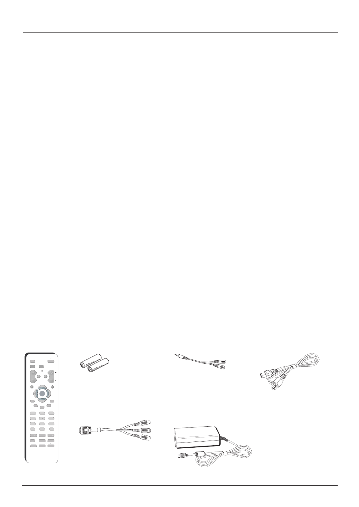
Check Supplied Parts
Check that the following parts were packed with your product.
ON OFF
DVD
VCR TV
MUTE GO BACK
OKOK
GUIDE
PLAY
STOP
ZOOM
SEARCH
CH
MENU
SKIP
INFO
56
89
ANTENNA
0
FORWARD
PAUSE
OPEN CLOSE
VOL
CLEAR
PRESETS
CC
123
4
7
INPUT
REVERSE
RECORD
AGAIN
SPEED
Remote Control
2 AAA batteries
15 pin D-sub to
component video cable
adapter (use with the
RGB/YPbPr jack)
3.5mm mini phone
to audio cable adapter
(use with the Audio In or
Audio Out jack, not the
headphone jack)
AC Power adapter
Power cord
Chapter 1 3
Graphics contained within this publication are for representation only.
Page 8
Connections & Setup
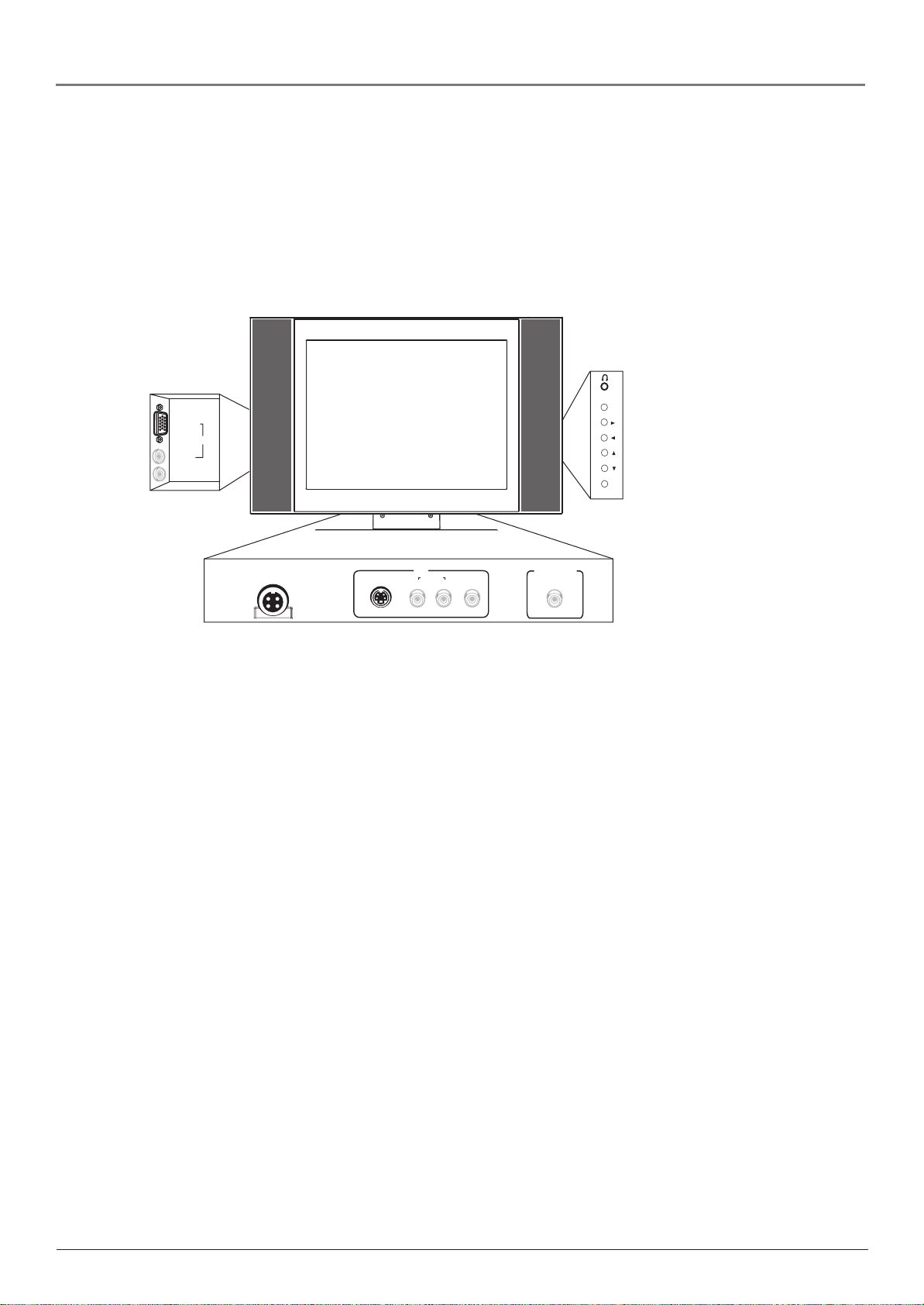
Explanation of Jacks
This section describes the jacks and cables you might use to make connections. There are
several ways to connect components to your TV.
Different jacks and cables provide a different level of performance. It’s important to remember
the different degrees of picture improvement for comparison. The RGB/YPbPr (component)
jack is considered an excellent improvement; S-Video and Video (composite) jacks are
considered very good; while the Antenna/Cable connection is good.
MENU
Back Panel
RGB/YPbPr
Audio In
Audio Out
VOL
VID2
Side Panel
CH
POWER
19V DC
Power In
S-Video In
VID1
R
Audio In
L/mono
Video In
Antenna/Cable
Bottom Panel (view from back,
starting from left)
Bottom Panel
19V DC Power In Connect the power adapter cord to this jack to give the TV power.
VID1
• S-Video In The S-Video (super video) jack provides better picture quality than the regular
video jack because the color (chrominance, also called chroma) part of the signal is
separated from the black and white (luminance) part of the picture.
If a component you’re connecting to your TV (like a DVD player) has an S-VIDEO jack,
connect the DVD player to the TV with an S-Video cable (not provided) for better quality
picture.
Note: Remember to connect the left and right audio cables to the VID1 Audio In jacks
because the S-Video cable carries only the picture signal, not the sound.
• Audio In R Provides right audio connection. The right audio connector is usually red.
• Audio In L/mono Provides left audio connection. The left audio connector is usually
white.
Note: If your component has only one output for audio (mono), connect it to the L/Mono
Audio jack on the TV and don’t connect the R Audio part of the cable. In this case, you
need to change a setting to hear sound from both speakers. Go to the Sound menu,
highlight Sound Type and then choose Mono.
• Video In Provides composite video connection. The video connector is usually yellow.
Antenna/Cable Lets you connect a coaxial cable to receive the signal from the antenna, cable,
or cable box.
4 Chapter 1Graphics contained within this publication are for representation only.
Page 9

Connections & Setup
Back Panel
VID2
• RGB/YPbPr (mini D-sub 15 pin) For connection of components that have RGB
or component output jacks (Y, Pb, Pr), such as a personal computer, HD receiver,
DVD player, or external RGB decoder.
The RGB/YPbPr jack provides excellent picture quality because the video is
separated into three signals. If your component has Y, Pb, Pr jacks, use the
supplied 15 pin D-sub to component video cable adapter. Connect component
video cables to the end of the adapter.
• Audio In (Stereo mini jack) Use to obtain sound when a component is
connected to the VID2 RGB/YPbPr jack. Use the supplied 3.5mm mini phone to
audio cable adapter. Connect audio cables to the end of the adapter.
• Audio Out (Stereo mini jack) Use to output the audio of the selected source
component connected to this unit to an AV amplifier or similar component. Use the
supplied 3.5mm mini phone to audio cable adapter. Connect audio cables to the
end of the adapter.
Side Panel
• Headphone Allows you to connect headphones to listen to the sound coming from the
TV.
Note: When you plug in headphones, the TV’s internal speakers are automatically turned
off.
If you can’t locate your remote, you can use the side panel of your TV to operate many of the
TV’s features.
MENU Brings up the Main menu. When the menu system is displayed, pressing MENU selects
highlighted items.
VOL
Increases the volume. In the menu system, it points right to items and adjusts menu
controls.
VOL
Decreases the volume. In the menu system, it points left to items and adjusts menu
controls.
CH
Scans up through the current channel list. In the menu system, it points down to items
and adjusts menu controls.
CH
Scans down through the channel list. In the menu system, it points up to items and
adjusts menu controls.
POWER Turns the TV on and off.
Note: If you use the Front Panel Block feature, the front panel buttons no longer provide
access to the menus. Go to Chapter 3 for more information.
Chapter 1 5
Graphics contained within this publication are for representation only.
Page 10
Connections & Setup
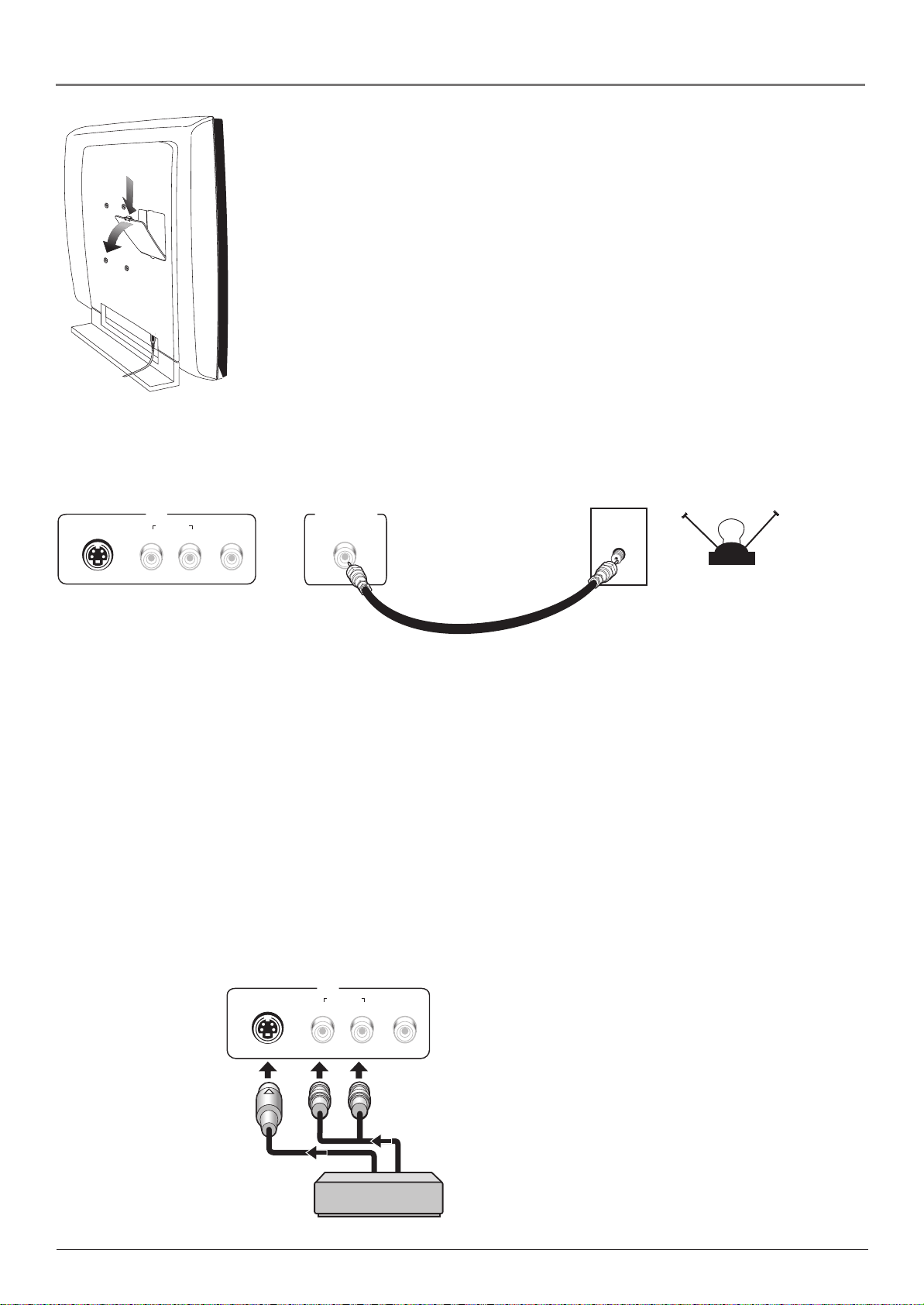
Remove the Plate On the Back Panel
You need to remove the plate on the back panel in order to use the jacks. As the
picture to the left shows, push down on the tab and pull out the back plate carefully.
When you are finished connecting a component to the jacks, replace the plate.
Connect Your Cable
Connect your cable or antenna to the Antenna/Cable jack on the bottom panel of the TV using
a coaxial cable.
S-Video In
VID1
R
Audio In
L/mono
Video In
Antenna/Cable
CABLE
OR
Choose Your Connection
There are several ways to connect your television, depending on the components you want to
connect and the quality of the signal you want to achieve. The following are examples of some
ways to connect your TV. Choose the connection which is best for you.
Connection to AV Components
Using VID1
Connect a component, such as a VCR, DVD player or Satellite Receiver, to the TV using the
VID1 jacks. Connect an S-Video cable to the S-Video In jack at the bottom panel of the TV and
to the S-Video Out Jack on the component. Then connect audio cables to the Audio In L/mono
and R jacks on the bottom panel of the TV and to the Audio Output jacks on the component.
Note: If the component you are connecting only has a Video Jack, connect the component
to the TV’s Video In jack using a video cable.
S-Video In
VID1
R
Audio In
L/mono
Video In
OFF-AIR ANTENNA
AV component
6 Chapter 1Graphics contained within this publication are for representation only.
Page 11
Connections & Setup
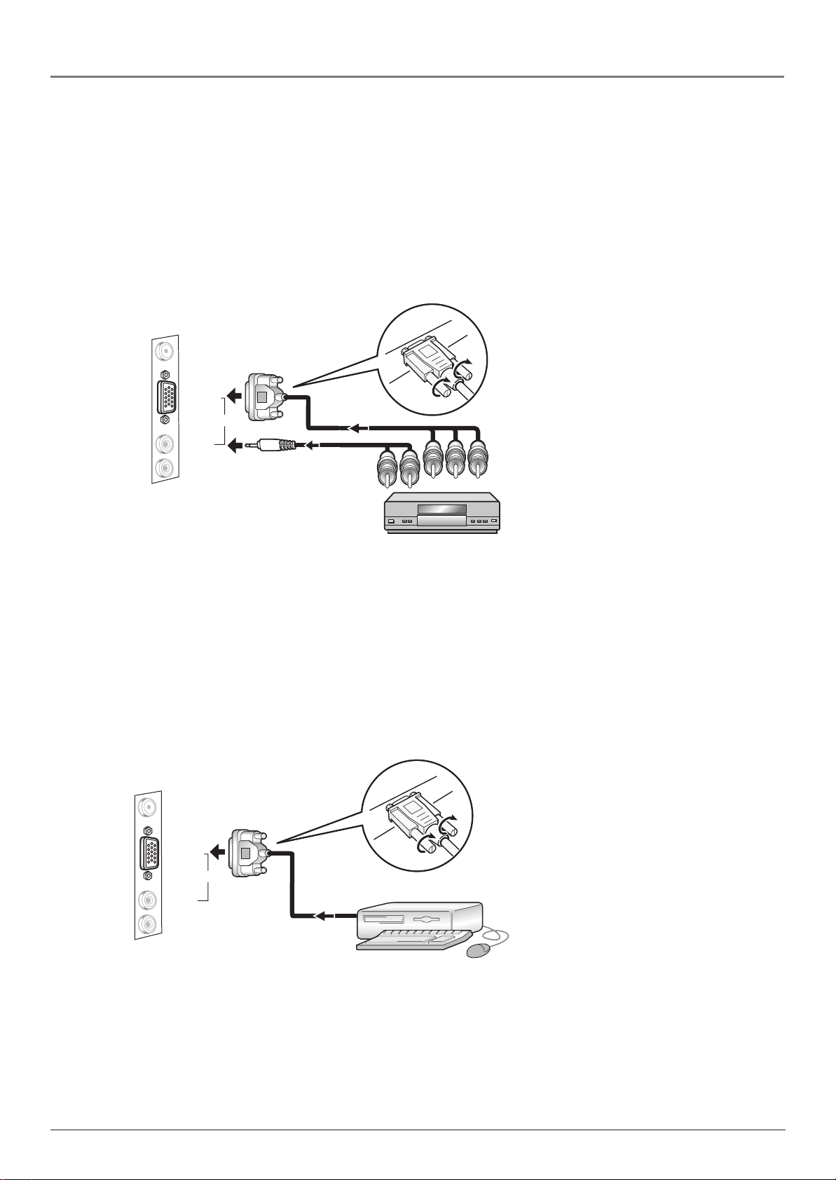
Using VID2
Connect a component, such as a DVD player or digital cable box, to the TV using the VID2
jacks. Connect the supplied 15 pin D-sub to component video cable adapter to the RGB/YPbPr
jack on the back of the TV. Then connect component video cables to the adapter and connect
the other end to the component video jacks (Y, Pb, Pr) on the component. Connect the
supplied 3.5mm mini phone to audio cable adapter to the Audio In jack on the back of the TV.
Connect audio cables to the adapter and connect the other end to the Audio Output jacks on
the component.
Note: If you connect a component using the VID2 jacks, you need to set the VID2 source in
the Setup menu. Go to page 10 for more information.
+12V Output
RGB/YPbPr
VID2
Audio In
Audio Out
AV component
Connection to a Personal Computer
Using VID2
Connect a personal computer to the TV using the VID2 RGB/YPbPr jack. Connect a 15-pin
monitor cable to the PC and the other end to the back of the TV.
Note: If you connect a component using the VID2 jacks, you need to set the VID2 source
in the Setup menu. Go to page 10 for more information.
The maximum panel resolution is 800 x 600. Be sure to set your PC to this monitor output
setting.
+12V Output
RGB/YPbPr
VID2
Audio In
Audio Out
Chapter 1 7
Graphics contained within this publication are for representation only.
Page 12
Connections & Setup
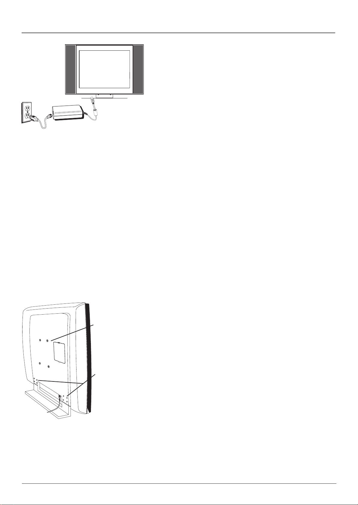
Plug in the TV
Plug the end of the cord from the power adapter into the 19V DC In
Power jack on the bottom panel of the TV. Then connect the end of
the power cord into the other end of the power adapter. Plug the end
of the power cord into an appropriate wall outlet. Be sure to insert the
plug completely. Do not plug into an outlet controlled by a light
switch.
Put batteries in the remote
• Remove the battery compartment cover from the back of the remote by pushing down on
and sliding off the cover.
• Insert 2 fresh “AAA” batteries. Make sure the polarities (+ and -) are aligned correctly.
• Replace the cover.
Turn on the TV
Press TV on the remote, or press POWER on the TV’s side panel.
Note: Pressing the TV button turns on the TV and puts the remote into TV mode. “TV
mode” means that the buttons on the remote control operate the TV’s functions.
Adjust the TV Screen
The TV’s screen is adjustable simply by pushing on the top, front part of the screen, while your
other hand holds the base of the TV.
Mounting the TV to the Wall
Wall mount
holes
Remove these
screws
Your LCD TV can be mounted to the wall using a compatible VESA
100 wall mount, which can be purchased at most electronic stores. To
mount the LCD TV you must first remove the stand.
1. Remove the four screws on either end of the bottom back panel.
2. Carefully lift up on the monitor until it slides out of place from the
stand.
3. Attach the wall mount to the four holes on the back middle part of
the TV.
4. Follow the directions that came with your wall mount.
Set Up Your TV
There are several options you might need to set up in order for your
TV to work properly. Turn on your TV, then press the MENU button
on your remote control. Follow the instructions on the next page.
8 Chapter 1Graphics contained within this publication are for representation only.
Page 13

MAIN MENU
Picture
Sound
Parental Control
Preferences
Setup
Preferences
Language English. . .
Press MENU or CLEAR to exit.
Closed Caption. . .
Menu Time-out 10 Seconds
Menu Position
Menu Background Opaque. . .
Sleep Timer 30 Minutes. . .
Press </> or OK to select.
Press MENU to go to Main Menu.
Connections & Setup
Choose the Menu Language
Select your preferred language for the menu system.
1. From the Main menu, press the down arrow button to highlight
Preferences, then press OK (the Preferences menu appears with
Language highlighted).
2. The default language is English. To select French or Spanish,
press the right arrow button.
MAIN MENU
Picture
Sound
Parental Control
Preferences
Setup
Setup
Press MENU or CLEAR to exit.
Signal Type Cable. . .
Auto Channel Search Start. . .
Autotuning. . .
Channel List. . .
Set VID2 Source PC. . .
Press </> to select.
Press MENU to go to Main Menu.
Setup
Signal Type Cable. . .
Auto Channel Search Start. . .
Autotuning. . .
Channel List. . .
Set VID2 Source PC. . .
Choose the Signal Type
In order for your TV to search for channels, you need to make sure
your signal type is set correctly.
1. Press the MENU button (the MAIN MENU appears).
2. Press the down arrow button to highlight Setup, then press OK
(the Setup menu appears with Signal Type highlighted).
3. The Signal Type option is set to Cable. To change the option to
Antenna, press the right arrow button.
Complete Channel Search
To search for all channels viewable through your antenna or cable TV
system:
1. From the Setup menu, press the down arrow button to highlight
Auto Channel Search.
2. Press the right arrow button to begin the channel search.
Note: Depending on the number of channels you receive, it
may take several minutes for the channel search to finish.
Press </> to start. Press MENU to go to Main Menu.
Press OK to stop search.
Chapter 1 9
Graphics contained within this publication are for representation only.
Page 14

Connections & Setup
Setup
Signal Type Cable. . .
Auto Channel Search Start. . .
Autotuning. . .
Channel List. . .
Set VID2 Source PC. . .
Press </> to select.
Press MENU to go to Main Menu.
Set VID2 Source
If you have a component connected to the VID2 jacks on the TV, you
need to set the VID2 source.
1. From the Setup menu, press the down arrow button to highlight
Set VID2 Source.
2. Press the right arrow button to select Y Pb Pr, if your component
connected to VID2 has Y, Pb, Pr jacks; or select PC if connected to
a PC.
10 Chapter 1Graphics contained within this publication are for representation only.
Page 15

Chapter 2: Using the Remote Control
VOL
Indicator
DVD
VCR TV
MUTE GO BACK
CLEAR
OKOK
PRESETS
CC
123
4
INFO
GUIDE
56
ON OFF
SKIP
MENU
Button Descriptions for TV Mode
Arrows Used to highlight different items in the TV menu and to
adjust the menu controls.
Indicator Indicates the programming mode when programming the
remote to control components. Lights when you press a valid button
on the remote. Flickers when a button is pressed and the batteries are
low.
CH
(0-9) Number Buttons Enter channel numbers and password
settings directly through the remote control.
To enter a one-digit channel, enter a zero first. To enter a two-digit
channel, press the two digits and expect a few seconds delay. This is if
you want to enter a third digit.
CC Brings up the Closed Caption menu.
CH + or CH - Scans up or down through the current channel list.
Press once to change the channel up or down; press and hold to
continue changing channels.
CLEAR Removes any menu or display from the screen and returns
you to normal viewing.
GO BACK Returns you to the previous channel.
7
INPUT
REVERSE
RECORD
AGAIN
SPEED
89
ANTENNA
0
FORWARD
PLAY
STOP
ZOOM
SEARCH
PAUSE
OPEN CLOSE
Tip
To turn off most RCA, GE, and Proscan
components that are connected to the TV, press
ON•OFF twice within two seconds.
This feature only works with most RCA, GE, and
Proscan products.
INFO Brings up the channel banner; press again to clear the screen.
INPUT Toggles through the available input sources (VID1, VID2-
YPbPr/VID2-PC and current channel).
MENU Brings up the Main menu.
MUTE Reduces the TV’s volume to its minimum level. Press again to
restore the volume.
OK When in the menu system, selects highlighted items.
ON•OFF When in TV mode, turns the TV on or off. If in another
mode (VCR or DVD) and programmed, will turn the component on or
off.
PRESETS Resets the picture settings to factory default for the video
input channel you’re currently tuned to.
SKIP Press once before changing channels and the TV will wait 30
seconds before returning to the original channel. Press repeatedly to
add more time.
TV Turns on the TV and puts the remote in TV mode. Also displays
current status.
VOL – or VOL + Decreases or increases the TV’s volume.
Button Descriptions for DVD and
VCR Modes
AGAIN In DVD mode, replays the last several seconds of the title
you’re playing.
ANTENNA In VCR mode, functions as a TV/VCR button.
Chapter 2 11
Graphics contained within this publication are for representation only.
Page 16

Using the Remote Control
DVD Puts the remote in DVD mode and, if auto tuning is enabled, will turn on the TV and
tune to the correct video input channel. Also used with the ON•OFF button to turn on other
compatible DVD players.
GUIDE If you’re operating another component that has an on-screen program guide, this
button accesses the on-screen guide.
OPEN•CLOSE In DVD mode, opens or closes the DVD disc tray.
REVERSE, PLAY, FORWARD, RECORD, STOP, PAUSE If programmed, provides transport
control for some remote-controllable VCRs or DVD players.
SEARCH In VCR mode, accesses Index Search feature.
SPEED In VCR mode, selects a recording speed.
VCR Puts the remote in VCR mode and, if auto tuning is enabled, will turn on the TV and
tune to the correct video input channel.
ZOOM In DVD mode, zooms in on the picture.
Using the INPUT Button
Use the INPUT button to scroll through the available video input channels and view
components you have connected to the TV.
1. Make sure the component you want to view is turned ON.
2. Press INPUT to tune to an available video input source and view the component.
3. To return to the previous channel, continue pressing INPUT.
Programming the Remote to
Operate Other Components
The universal remote can be programmed to operate most brands of
remote controllable components. The remote is already programmed
DVD
and VCR
buttons
DVD
VCR TV
ON OFF
ON•OFF
button
VOL
MUTE GO BACK
CH
to operate most RCA, GE, and Proscan components.
CLEAR
button
REVERSE
and PLAY
buttons
CLEAR
PRESETS
CC
123
4
7
INPUT
REVERSE
RECORD
AGAIN
SPEED
OKOK
SKIP
INFO
GUIDE
56
89
ANTENNA
0
FORWARD
PLAY
PAUSE
STOP
ZOOM
OPEN CLOSE
SEARCH
MENU
STOP
button
Notes: The TV button can’t be programmed on this remote.
The remote may not be compatible with all brands and models
of components. It also may not operate all functions of the
remote that came with your component.
Find Out If You Need to Program the Remote
To determine whether the universal remote needs to be programmed
for your component, turn the component ON. For example, to
program the remote for a VCR, turn on the VCR. Point the remote at
the VCR, and press the VCR button. Then press ON•OFF or CH +
(channel up) or CH – (channel down) to see if the VCR responds to
the remote commands. If the component does not respond, the remote
needs to be programmed.
You’ll use these buttons when
you program the remote.
Programming the Remote
There are two ways to program the remote control:
• automatic code search
• direct entry
12 Chapter 2
Graphics contained within this publication are for representation only.
Page 17

Using the Remote Control
Using Automatic Code Search
The following instructions can be used to program the remote to operate each of your components. If
you want to stop the automatic code search without programming any of your components, press CLEAR
until the indicator on the remote turns off.
1. Turn on the component you want to operate (VCR or DVD player)
2. Press and hold the component button you want to program (VCR or DVD). While holding the
component button, press and hold ON•OFF until the indicator on the remote turns on, then release
both buttons.
3. Point the remote at the component. Press and release PLAY (the indicator light on the remote flashes).
The remote is searching for the correct code to program. When the indicator stops flashing (after
about 5 seconds), press PLAY again to tell the remote to search the next set of codes.
Continue pressing PLAY until the component turns off or the indicator light on the remote turns off. If
the indicator light turns off, then all the codes for that particular component have been tested once. If
the component does not turn off, then the remote can’t be programmed to operate that component.
Note: Each time you press PLAY, the remote sends about 10 sets of codes. Therefore, you might have
to press the PLAY button up to 20 times.
If the component you want to operate does turn off:
1. Press and release REVERSE, then wait 2 seconds. Repeat this step until the device turns back ON.
2. To finish, press and hold STOP until the indicator on the remote turns off.
Using Direct Entry
1. Turn on the component to be programmed.
2. Look up the brand and code number(s) for the component on the code list in this section.
3. Press and hold the component button you want to program on the remote.
4. Enter the code from the remote control code list on the following pages. If the indicator flashes, you
have either entered an invalid code or the button isn’t programmable.
5. Release the component button.
6. Point the remote at the component. Press ON•OFF to see if the component responds to the
command. If it doesn’t, try pressing the component button and then ON•OFF again.
• If you get no response, repeat these steps using the next code listed for your brand, until the
component responds to the remote commands.
• If you try all the codes for your component brand and none work, try the automatic code search
method. If automatic code search doesn’t find the code, the remote is not compatible with your
component.
How to Use the Remote After You’ve Programmed It
Because this universal remote can operate several different components, it uses operational modes
triggered by the component buttons. For example, if you want the remote to operate the TV, you would
press the TV button to put the remote into TV mode before you could operate the TV.
1. Press the appropriate component button (DVD, TV, VCR) to set the remote to operate the component.
2. Press ON•OFF to turn the component ON or OFF.
3. Use the remote buttons that apply to that component.
Note: If you keep pressing buttons and nothing happens, the remote is probably in the wrong
mode. You must press the component button that matches the component you want to operate (i.e.,
if you want to operate the VCR, press VCR on the remote control to put the remote in VCR mode.)
Chapter 2 13
Graphics contained within this publication are for representation only.
Page 18

Using the Remote Control
Remote Control Codes
VCR Codes
Programmable for VCR button.
Admiral ....................................................................................................................... 2132
Adventura ................................................................................................................... 2026
Aiko ............................................................................................................................ 2027
Aiwa ............................................................................................................................ 2026
Akai ....................................................... 2003, 2004, 2005, 2007, 2008, 2111, 2112, 2113
American High ........................................................................................................... 2021
Asha ............................................................................................................................ 2013
Audio Dynamics ............................................................................................... 2009, 2010
Audiovox .................................................................................................................... 2014
Bell & Howell ............................................................................................................ 2011
Beaumark ................................................................................................................... 2013
Broksonic ......................................................................................................... 2012, 2025
Calix ............................................................................................................................ 2014
Candle ......................................................................................... 2013, 2014, 2015, 2016,
................................................................................................................ 2017, 2018, 2019
Canon ..................................................................................................... 2021, 2022, 2114
Capehart ........................................................................................................... 2020, 2110
Carver ......................................................................................................................... 2062
CCE ................................................................................................................... 2027, 2061
Citizen .............................................................................................................. 2013, 2014,
.................................................................................. 2015, 2016, 2017, 2018, 2019, 2027
Colortyme ................................................................................................................... 2009
Colt ............................................................................................................................. 2061
Craig ............................................................................................. 2013, 2014, 2023, 2061
Curtis-Mathes ......................................................................................... 2000, 2009, 2013,
........................................................................ 2016, 2018, 2021, 2022, 2024, 2115, 2131
Cybernex .................................................................................................................... 2013
Daewoo ................................................ 2015, 2017, 2019, 2025, 2026, 2027, 2028, 2110
Daytron ....................................................................................................................... 2110
DBX .................................................................................................................. 2009, 2010
Dimensia .......................................................................................................... 2000, 2131
Dynatech .................................................................................................................... 2026
Electrohome ..................................................................................................... 2014, 2029
Electrophonic ............................................................................................................. 2014
Emerson ................................................................... 2012, 2014, 2015, 2021, 2024, 2025,
............. 2026, 2029, 2030, 2031, 2032, 2033, 2034,2035, 2036, 2037, 2038, 2039, 2040,
.................................. 2041, 2042,2044, 2045, 2046, 2047, 2065, 2113, 2116, 2117, 2130
Fisher .................................................... 2011, 2023, 2048, 2049, 2050, 2051, 2052, 2118
Fuji .................................................................................................................... 2021, 2119
Funai ........................................................................................................................... 2026
Garrard ....................................................................................................................... 2026
GE .......................................................................................................... 2000, 2001, 2013,
.................................................................................. 2021, 2022, 2053, 2115, 2120, 2131
Goldstar ........................................................................................ 2009, 2014, 2018, 2054
Gradiente .................................................................................................................... 2026
Harley Davidson ........................................................................................................ 2026
Harman Kardon ......................................................................................................... 2009
Harwood .................................................................................................................... 2061
Headquarter ............................................................................................................... 2011
Hitachi ............................................................................................................. 2055, 2056,
............................................................................................ 2057, 2107, 2111, 2120, 2122
Hi-Q ............................................................................................................................ 2023
Instant Replay ............................................................................................................ 2021
JCL .............................................................................................................................. 2021
JC Penney .................................................................................... 2009, 2010, 2011, 2013,
........................................................................................... 2014, 2021, 2022, 2055, 2056,
............................................................................................ 2058, 2059, 2060, 2107, 2118
Jensen ..................................................................................................... 2055, 2056, 2111
JVC ............................................................................ 2009, 2010, 2011, 2018, 2111, 2123
Kenwood ........................................................ 2009, 2010, 2011, 2016, 2018, 2111, 2123
KLH ............................................................................................................................. 2061
Kodak ............................................................................................................... 2014, 2021
Lloyd ........................................................................................................................... 2026
Logik ........................................................................................................................... 2061
LXI .............................................................................................................................. 2014
Magnavox .............................................................................................. 2021, 2022, 2062,
............................................................................................ 2063, 2104, 2105, 2108, 2124
Magnin ........................................................................................................................ 2013
Marantz ................................................. 2009, 2010, 2011, 2016, 2018, 2021, 2062, 2064
Marta ........................................................................................................................... 2014
Masushita .................................................................................................................... 2021
Mei .............................................................................................................................. 2021
Memorex .............................................. 2011, 2013, 2014, 2021, 2023, 2026, 2104, 2132
MGA ........................................................................................................ 2029, 2065, 2113
MGN Technology ....................................................................................................... 2013
Midland ....................................................................................................................... 2053
Minolta .................................................................................................... 2055, 2056, 2107
Mitsubishi ...................................................... 2029, 2055, 2056, 2065, 2066, 2067, 2068,
................................................... 2069, 2070, 2071, 2072, 2073, 2074, 2106, 2113, 2123
Montgomery Ward ........................................................................................... 2075, 2132
Motorola ........................................................................................................... 2021, 2132
MTC .................................................................................................................. 2013, 2126
Multitech ............................................................................. 2013, 2016, 2026, 2053, 2061
NEC ..................................................................................... 2009, 2010, 2011,2016, 2018,
.................................................................................. 2064, 2076, 2078, 2079, 2111, 2123
Nikko .......................................................................................................................... 2014
Noblex ........................................................................................................................ 2013
Olympus .................................................................................................................. 2021
Optimus ......................................................................................................... 2014, 2132
Optonica .................................................................................................................. 2096
Panasonic .............................................................. 2021, 2022, 2109, 2125, 2126, 2127
Pentax .............................................................................. 2016, 2055, 2056, 2107, 2120
Pentex Research ...................................................................................................... 2018
Philco ......................................................................................... 2021, 2022, 2062, 2063
Philips ........................................................................................ 2021, 2062, 2096, 2124
Pilot .......................................................................................................................... 2014
Pioneer ............................................................................ 2010, 2055, 2080, 2081, 2123
Portland ..................................................................................... 2016, 2017, 2019, 2110
Proscan ................................................................................................ 2000, 2001, 2131
Protec ....................................................................................................................... 2061
Pulsar ....................................................................................................................... 2104
Quarter .................................................................................................................... 2011
Quartz ...................................................................................................................... 2011
Quasar ................................................................................................. 2021, 2022, 2125
RCA ............................................................. 2000, 2001, 2003, 2013, 2021, 2055, 2056,
......................................................... 2082, 2083, 2084, 2085, 2086, 2087, 2088, 2089,
........................................................... 2090, 2091, 2107, 2115, 2120, 2125, 2131, 2133
Radioshack/Realistic ................................................................ 2011, 2013, 2014, 2021,
........................................................... 2022, 2023, 2026, 2029, 2049, 2050, 2096, 2132
Radix ........................................................................................................................ 2014
Randex ..................................................................................................................... 2014
Ricoh ........................................................................................................................ 2128
Runco ...................................................................................................................... 2104
Samsung ................................................................ 2005, 2013, 2015, 2033, 2053, 2112
Sanky ............................................................................................................. 2104, 2132
Sansui ........................................................................................ 2010, 2092, 2111, 2123
Sanyo ................................................................................................... 2011, 2013, 2023
Scott ................................................... 2012, 2015, 2025, 2032, 2038, 2065, 2093, 2116
Sears ............................................................................... 2011, 2014, 2021, 2023, 2048,
.................................................................... 2049, 2050, 2051, 2055, 2056, 2107, 2118
Sharp ............................................................ 2017, 2029, 2094, 2095, 2096, 2097, 2132
Shintom ..................................................................................... 2004, 2056, 2061, 2098
Shogun .................................................................................................................... 2013
Signature .................................................................................................................. 2132
Singer ................................................................................................... 2021, 2061, 2128
Sony ........................................................................................... 2004, 2098, 2099, 2119
STS ................................................................................................................. 2021, 2107
Sylvania ....................................................... 2021, 2022, 2026, 2062, 2063, 2065, 2124
Symphonic ............................................................................................................... 2026
Tandy ....................................................................................................................... 2011
Tashiko .................................................................................................................... 2014
Tatung ...................................................................................................................... 2111
TEAC .................................................................................................... 2026, 2085, 2111
Technics......................................................................................................... 2021, 2109
Teknika ............................................................................ 2014, 2021, 2026, 2100, 2129
TMK ..................................................................................................... 2013, 2024, 2047
Toshiba ........................................................ 2015, 2049, 2051, 2055, 2065, 2093, 2116
Totevsion ....................................................................................................... 2013, 2014
Unitech .................................................................................................................... 2013
Vector Research......................................................................... 2009, 2010, 2015, 2016
Victor ....................................................................................................................... 2010
Video Concepts ............................................................... 2009, 2010, 2015, 2016, 2113
Videosonic ............................................................................................................... 2013
Wards ........................................................................................ 2013, 2014, 2015, 2021,
............................................................................. 2023, 2026, 2029, 2055, 2056, 2061,
.................................................................... 2096, 2101, 2102, 2103, 2107, 2116, 2132
XR-1000 ............................................................................................... 2021, 2026, 2061
Yamaha ............................................................................ 2009, 2010, 2011, 2018, 2111
Zenith .............................................................................. 2004, 2098, 2104, 2119, 2128
Programmable for DVD button.
Aiwa ......................................................................................................................... 3009
Apex .............................................................................................................. 3023, 3024
GE ............................................................................................................................ 3000
Hitachi ..................................................................................................................... 3008
JVC ................................................................................................................. 3002, 3010
Konka ............................................................................................................ 3011, 3012
Magnavox ................................................................................................................ 3003
Mitsubishi ................................................................................................................ 3004
Panasonic ................................................................................................................ 3013
Philips ........................................................................................ 3003, 3019, 3021, 3022
Pioneer .................................................................................................................... 3005
Proscan .................................................................................................................... 3000
RCA ................................................................................................................ 3000, 3001
Samsung .................................................................................................................. 3025
Sanyo ....................................................................................................................... 3014
Sony ..................................................................................................... 3006, 3015, 3016
Toshiba ................................................................................................ 3007, 3017, 3020
Zenith ...................................................................................................................... 3018
DVD codes
14 Chapter 2
Graphics contained within this publication are for representation only.
Page 19

Chapter 3: Using the TV’s Features
8
Commercial Skip Timer 00:00:30
Sleep Timer 01:30
About the Channel Banner
The Channel Banner appears when you press the TV or INFO button
on the remote. The following list describes the items on the Channel
Banner screen (left to right and top to bottom). Other displays that are
not described here are self-explanatory.
The icons change appearance to show the item’s status or availability.
8 Displays the current channel you are watching or input you are
tuned to.
Mute Icon Displayed when you mute the sound.
Parental Controls Lock Icon Displayed when Parental Controls are
locked.
Commercial Skip Timer 00:00:30 Corresponds to the SKIP button.
Shows the amount of time left before the TV switches back to the
previous channel.
Sleep Timer 01:30 Displays the amount of time remaining before
the TV turns off if you have set the sleep timer.
Why You Should Use the Autotuning Feature
The autotuning feature tunes the TV to the correct channel for different components you have
connected to your TV (like a VCR or DVD Player). When you set up autotuning in the menu
system, you don’t have to remember to change your TV to channel 3, for example, when you
want to watch the tape in your VCR.
How to Set Up the Autotuning Feature
The way you set up the autotuning feature in the TV’s menu corresponds to the component
buttons on the remote and the way you have each component connected to your TV. When
you set up autotuning, you’re telling the TV what channel to tune to when you press the VCR
or DVD button on the remote control.
1. Press MENU (the MAIN MENU appears).
2. Highlight Setup and press OK on your remote control.
3. Highlight Autotuning and press OK.
4. Choose which channel you want to set:
Set VCR Ch/Input Lets you set up the channel the TV tunes to when you press the VCR
button.
Set DVD Ch/Input Lets you set up the channel the TV tunes to when you press the DVD
button.
5. Press the right arrow button to select the choice that matches the way you have the
component connected to this TV.
The choices and a brief explanation follow:
Chapter 3 15
Graphics contained within this publication are for representation only.
Page 20

Using the TV’s Features
N/A Choose this if you don’t have this particular component
Autotuning
Set VCR Ch/Input 03. . .
Set DVD Ch/Input VID2. . .
Press </> or OK to select.
Press MENU to go to Setup Menu.
connected to the TV, or if you don’t want the TV to automatically tune
to the correct channel when you’re using this component.
03 Component is connected to the Antenna/Cable jack on the bottom
panel of the TV, and you want the TV to tune to channel 3 or 4 when
you press the corresponding button on the remote. Reminder: make
sure the component’s Channel 3/4 switch is set to the appropriate
channel.
VID1 Component is connected to the VID1 Video In or S-Video In
jack on the bottom panel of the TV and you want the TV to tune to a
video input channel when you press the corresponding button.
VID2 Component is connected to the VID2 RGB/YPbPr jack on the
back of the TV and you want the TV to tune to a component video
input channel when you press the corresponding button.
Parental Controls
Parental Control
US V-Chip. . .
Canada V-Chip. . .
V-Chip Unrated/Exempt View . . .
Front Panel Block
Channel Block. . .
Lock Parental Controls. . .
Press </> or OK to go to the sub-menu.
Press MENU to go to Main Menu.
The Parental Control menu allows you to program your TV so that
children cannot see certain programs, channels, or use the front panel
controls. The Parental Control menu also involves software inside
your TV (referred to as V-Chip) which lets you program your TV so it
won’t display certain programs and movies based on violence, sex, or
other content you may believe children should not view. Once you
block programs, you or other adults can unblock programs by
entering a password to unlock video or enter the password to edit the
features in the Parental Control menu. By default, the software inside
your TV is turned “off,” so if you don’t want to use this feature, you
can just ignore it.
How V-Chip Works
The V-Chip software reads a code that most broadcasters send with
programs. That code tells the software the program’s age-based rating
(TV-MA, TV-14, etc.) and content themes [(Violence (V), Adult
Language (L), etc.)]. If you have blocked the rating and/or content
themes that the program contains and the TV is locked and you tune
to a program whose rating exceeds the rating limit you set, you will
receive a message telling you that the program is not approved for
viewing.
Broadcasters are not required to provide content themes, so programs
received with no content themes will only be blocked if you block their
age-based rating and the TV is locked. You can also block out programs
that have been given a rating of Not Rated, and programs that are
considered unrated. The TV age-based ratings and content themes you
can block are listed on the next page.
16 Chapter 3
Graphics contained within this publication are for representation only.
Page 21

Using the TV’s Features
US V-Chip Rating System
TV-MA (Mature Audience Only) Specifically designed to be viewed by adults and may be
unsuitable for children under 17. It contains one or more of the following content themes:
crude indecent language (L), explicit sexual activity (S), or graphic violence (V).
TV-14 (Parents Strongly Cautioned) Contains some material that many parents would find
unsuitable for children under 14. Parents are strongly urged to exercise greater care in
monitoring this program and are cautioned against letting children under the age of 14 watch
unattended. This program contains one or more of the following content themes: intensely
suggestive dialogue (D), strong coarse language (L), intense sexual situations (S), or intense
violence (V).
TV-PG (Parental Guidance Suggested) Contains material that parents may find unsuitable for
younger children. Many parents may want to watch it with their younger children. The
program contains one or more of the following content themes: some suggestive dialogue (D),
infrequent coarse language (L), some sexual situations (S), or moderate violence (V).
TV-G (General Audience) Most parents would find this program suitable for all ages. It
contains little or no sexual dialogue (D) or situations (S), no strong language (L), and little or
no violence (V).
TV-Y7 (Directed to Children 7 years and older) Designed for children ages 7 and above. It
may be more appropriate for children who have acquired the developmental skills needed to
distinguish between make-believe and reality. Themes and elements in this program may
include mild fantasy violence (FV) or comedic violence, or may frighten children under the age
of 7.
TV-Y (All Children) Themes and elements in this program are designed for a young audience,
including children from ages 2-6. It is not expected to frighten younger children.
Canadian English V-Chip Rating System
18+ (Adults) Programming intended for adults 18 and older. It may contain elements of
violence, language, and sexual content which could make it unsuitable for viewers under 18.
Violence Guidelines: May contain violence integral to the development of the plot, character or
theme, intended for adult audiences. Other Content Guidelines: May contain graphic language
and explicit portrayals of nudity and/or sex.
14+ (Viewers 14 and over) Programming contains themes or content which may not be
suitable for viewers under the age of 14. Parents are strongly cautioned to exercise discretion in
permitting viewing by pre-teens and early teens. Violence Guidelines: May contain intense
scenes of violence. Could deal with mature themes and societal issues in a realistic fashion.
Other Content Guidelines: May contain scenes of nudity and/or sexual activity. There could be
frequent use of profanity.
PG (Parental Guidance) Programming intended for a general audience but which may not be
suitable for younger children (under the age of 8). Parents may consider some content
inappropriate for unsupervised viewing by children aged 8-13. Violence Guidelines: Depictions
of conflict and/or aggression will be limited and moderate; may include physical, fantasy, or
supernatural violence. Other Content Guidelines: May contain infrequent mild profanity, or
mildly suggestive language. Could also contain brief scenes of nudity.
G (General Audience) Programming considered acceptable for all ages groups. While not
designed specifically for children, it is understood younger viewers may be part of the
audience. Violence Guidelines: Will contain very little violence, either physical or verbal or
emotional. Will be sensitive to themes which could frighten a younger child, will not depict
realistic scenes of violence which minimize or gloss over the effects of violent acts. Other
Content Guidelines: There may be some inoffensive slang, no profanity and no nudity.
Chapter 3 17
Graphics contained within this publication are for representation only.
Page 22

Using the TV’s Features
C8+ (Children 8 and Older) Programming generally considered acceptable for children 8
years and over to watch on their own. Violence Guidelines: Violence will not be portrayed as
the preferred, acceptable, or only way to resolve conflict or encourage children to imitate
dangerous acts which they may see on television. Any realistic depictions of violence will be
infrequent, discreet, of low intensity and will show the consequences of the acts. Other Content
Guidelines: There will be no profanity, nudity or sexual content.
C (Children) Programming intended for children under age 8. Violence Guidelines: Careful
attention is paid to themes which could threaten children’s sense of security and well being.
There will be no realistic scenes of violence. Depictions of aggressive behaviour will be
infrequent and limited to portrayals that are clearly imaginary, comedic or unrealistic in nature.
Other Content Guidelines: There will be no offensive language, nudity or sexual content.
Canadian French V-Chip Rating System
18+ (Adults) Programming is for adults only. This program contains sustained violence or
extremely violent scenes.
16+ (Viewers 16 and over) Programming is not suitable for those under age 16. This program
contains frequent scenes of violence or intensely violent scenes.
13+ (Viewers 13 and over) Programming may not be suitable for children under the age of
13. This program either contains several violent scenes or one or more scenes that are violent
enough to affect them. Viewing in the company of an adult is therefore strongly recommended
for children under the age of 13.
8+ (Viewers 8 and over) Not recommended for young children. This program is suitable for
most audiences, but it contains mild or occasional violence that could upset young children.
Viewing in the company of an adult is therefore recommended for young children (under the
age of 8) who do not distinguish between reality and imagination.
G (General Audience) This program is suitable for audiences of all ages. It contains no
violence, or any violence that it does contain is either minimal or is presented in a humorous
manner, as a caricature, or in an unrealistic way.
V-Chip TV Ratings
Parental Control
US V-Chip. . .
Canada V-Chip. . .
V-Chip Unrated/Exempt View. . .
Front Panel Block
V-Chip TV Ratings. . .
Channel Block. . .
V-Chip Movie Ratings. . .
Lock Parental Controls. . .
Press </> or OK to go to the sub-menu.
Press MENU to go to Main Menu.
US V-Chip
V-Chip TV Ratings
Rating TV-MA. . .
Status View. . .
L View. . .
S View. . .
V View. . .
The V-Chip TV Rating lets you decide which TV programs can and
cannot be viewed. To set TV programming limits:
1. Choose Parental Control from the Main menu. If Parental Control
has previously been locked, you must enter your password.
2. Highlight and select US V-Chip.
3. Press OK to select V-Chip TV Ratings.
4. Once you get to the V-Chip TV Ratings screen, use the arrow
buttons and OK on your remote to change the status of a TV
program rating or content theme from View to Block.
Proceed to the next sections for more details about how to change the
status of TV program limits.
Press </> to select program rating.
Press MENU to go to US V-Chip Menu.
18 Chapter 3
Graphics contained within this publication are for representation only.
Page 23

Using the TV’s Features
The V-Chip Rating Limit Screen
The following is an example of where items are located within the V-Chip TV Ratings screen.
Rating Status Field
Lets you select whether the status
of the age-based rating limit
above is View or Block.
Content Themes
Lists the content themes you
can block or view.
Rating Settings Area
Lets you see the current block/view state of agebased ratings and associated content.
Hierarchy of Age-Based Ratings
TV-MA Mature Audience Only
TV-14 Parents Strongly Cautioned
TV-PG Parental Guidance Suggested
TV-G General Audience
TV-Y7 Directed to Children 7 years
and older
TV-Y All Children
V-Chip TV Ratings
Rating TV-MA. . .
Status View. . .
L View. . .
S View. . .
V View. . .
Press </> to select program rating.
Press MENU to go to US V-Chip Menu.
Blocking Age-Based Ratings
You can automatically block all program ratings above a specified agebased rating level. For example, if you only want your child to watch
programs that have a TV-G rating and lower (in other words, you want
the child to watch TV-G, TV-Y7, and TV-Y), then you need to block
out higher ratings.
To block programs with higher ratings:
1. First, determine the lowest level rating you don’t want the child to
watch.
2. Highlight the lowest rating you do not want the child to watch. In
the example discussed above, you would highlight TV-PG, since
the highest rating you want the child to watch is TV-G.
Rating Field
Lets you select the age-based rating
you want to block or view.
Content Status Fields
Lets you select which content themes
to view for the selected rating, and
whether the status of the content
theme is currently View or Block.
3. Highlight Status. Press the OK button to toggle between View and
Block. The status for the rating you chose and all higher ratings
automatically change to Block.
4. Select Lock Parental Controls from the Parental Control menu.
Enter a password and if haven’t set your password, you’ll need to
re-enter the password a second time to confirm.
Viewing Age-Based Ratings
After you block age-based ratings, you have the option of changing
some of the ratings back to View.
1. Determine which blocked rating you want to view.
2. Use the up and down arrow buttons to highlight the rating with a
status of Block.
3. Press the OK button to select View.
Chapter 3 19
Graphics contained within this publication are for representation only.
Page 24

Using the TV’s Features
Blocking Specific Content Themes
V-Chip TV Ratings
Rating TV-14. . .
Status View. . .
D View. . .
L Block. . .
S View. . .
V View. . .
Press </> or OK to View/Block programs with this content
for this rating.
Press MENU to go to US V-Chip Menu.
Content Themes
D Sexually explicit dialogue
L Adult language
S Sexual situations
VViolence
FV Fantasy Violence
You can block programs based on their content. (Content is
represented by the D, L, S, V and FV on your screen.) When you block
a content theme for a particular rating, you automatically block that
content theme for higher rated programs as well.
To block program content:
1. Determine the content themes you want to block.
2. Highlight Rating, then press the right arrow to select the age-based
rating you want to change.
3. Press the down arrow button to highlight a particular content
theme.
4. Press the OK button to change its status to Block. (In the example
to the left, you block the language (L) corresponding with TV-14.
The language for TV-MA is blocked as well).
Notes: Broadcasters are not required to provide content themes
or age-based ratings.
You must remember to activate Parental Controls for rating
limits to take effect.
Viewing Specific Content Themes
1. Determine the content themes you want to change to View.
2. Highlight Rating.
3. Press the right arrow button to select the rating whose content
theme you want to change, such as Block next to language (L)
corresponding with TV-14.
4. Press the down arrow button to move the highlight to a particular
content theme.
5. Press the OK button to change the status back to View. Your child
would then be able to watch programs with the TV-14 adult
language content, but not programs with TV-MA language content.
Note: Only the content theme status corresponding to TV-14
(L) language changes to (V) View. Higher rated content themes,
such as that for TV-MA language, do not change.
V-Chip Movie Rating Limit
You set movie rating limits by blocking movies rated above a specified
rating. How to block movie ratings and view movie ratings is
explained in the next two sections.
To access the V-Chip Movie Rating menu:
1. Press MENU on the remote control (the MAIN MENU appears).
2. Press the down arrow button to select Parental Control.
3. Select US V-Chip.
4. Select V-Chip Movie Ratings.
20 Chapter 3
Graphics contained within this publication are for representation only.
Page 25

Using the TV’s Features
Blocking Movie Ratings
If you only want your child to watch movies that have a PG rating and lower (in other words, movies
rated PG and G), then you could automatically block out all other movies with higher ratings.
To block movies:
1. Highlight the rating that is the lowest rating you don’t want the child to watch. (In the example above,
you would highlight the rating status button corresponding to PG-13, since the highest rating you want
the child to watch is PG.)
2. Press the OK button to change from View to Block. All higher ratings automatically change to Block.
3. If the TV is not locked, you must lock it so the movie rating limits will take effect.
Note: Some movies may be given a Not Rated (NR) rating. After blocking movie ratings, you must
unlock NR separately in order to view movies with an NR rating.
Viewing Movie Ratings
After you block movie ratings, you have the option of changing some of the rating status buttons back to
View:
1. Highlight the rating you want to view.
2. Press the OK button to change the button from Block to View.
For example, if movies with a rating of PG-13 and higher are blocked, you can change the rating
status corresponding with NC-17. Your child would then be able to watch all movies with a G, PG,
and NC-17 Rating.
3. Exit the screen, and be sure the TV is locked.
Blocking Canadian V-Chip Ratings
French Ratings
Status
Rating 18+ View. . .
Rating 16+ View. . .
Rating 13 View. . .
Rating 8+ View. . .
Rating G View. . .
Press </> or OK to View/Block programs
with this rating.
Press MENU to go to CA V-Chip Menu.
English Ratings
Status
Rating 18+ View. . .
Rating 14+ View. . .
Rating PG View . . .
Rating G View. . .
Rating C8+ View. . .
Rating C View. . .
Press </> or OK to View/Block programs
with this Rating.
Press MENU to go to CA-V-Chip Menu.
If you receive Canadian programs you can block Canadian English and
French V-Chip by ratings only. When you block a particular rating,
you automatically block the higher rated programs as well.
To block Canadian English and French program ratings:
1. Select Canada V-Chip from the Parental Control menu.
2. Highlight English Ratings or French Ratings and press OK.
3. Determine the rating you want to block.
4. Press the down arrow button to scroll to the rating you want to
change.
5. Press the OK button to change its status to Block. All ratings above
the one you selected change to Block.
Chapter 3 21
Graphics contained within this publication are for representation only.
Page 26

Using the TV’s Features
V-Chip Unrated/Exempt Block
The V-Chip Unrated/Exempt option lets you decide if programs that the V-Chip recognizes as
unrated can be viewed. Unrated TV programs may include news, sports, political, religious,
local and weather programs, emergency bulletins, public announcements, and programs
without ratings. The V-Chip Unrated/Exempt option applies to both US and Canadian unrated
programs and Canadian programs rated E.
View All unrated programs are available.
Block All unrated programs are not available.
Note: You must remember to lock Parental Controls for rating limits to take effect.
Press the down arrow to highlight V-Chip Unrated/Exempt. Then press the right arrow to toggle
between View and Block.
Front Panel Block
Selecting this option lets you block (disable) or unblock (enable) the TV’s front panel buttons.
The remote still tunes to any channel. Front Panel Block can:
• Keep children from watching TV when the parent is not present.
• Keep young children from playing with the buttons on the TV.
(When using this as a Parental Control method, you should remove access to any remote that
is capable of operating the television while you have the front panel blocked.)
Don’t forget to lock the TV after you disable Front Panel Block (box has check mark). If you do
not, the front panel block will not take effect.
Note: If power to the TV is lost for more than an hour, the buttons become unblocked
To temporarily override front panel block, make sure no menus are displayed on-screen.
Simultaneously press and hold the MENU button on the TV’s side panel and CLEAR on the
remote for approximately 10 seconds.
Channel Block
Selecting this option lets you decide the channels you want to block. Use the number buttons
to enter the channel you want to view or block, then press OK.
If the Block box doesn’t have a check mark, the selected channel is viewable. If the box has a
check mark and you tune to a blocked channel, you need to enter a password to view the
channel.
Don’t forget to lock parental controls after you change the status of Channel Block. If you don’t
lock Parental Controls, the channel block will not take effect.
22 Chapter 3
Graphics contained within this publication are for representation only.
Page 27

Using the TV’s Features
Lock/Unlock Parental Controls
Selecting this option lets you activate and deactivate parental control settings.
1. From the Parental Control menu, press the down arrow button to highlight Lock Parental
Controls.
2. Press the OK button to activate the lock setting. Enter a password. To unlock Parental
Controls, follow these same steps.
If you do not Lock Parental Controls, none of the settings for V-Chip will take effect.
If you forget your password you can reset it. Make sure no menus are displayed on-screen.
Simultaneously press and hold VOL < on the TV’s side panel and the OK button on the remote
for approximately 10 seconds. Enter a new password next time you access the Lock Parental
Controls menu.
Additional Features
There are additional features available through the menu system, such as:
• Picture adjustments for each video input
• Sound adjustments
• Backlight adjustment
• Black level adjustment
• Noise reduction
• Film Mode (3:2 Reverse Pulldown)
• Sleep Timer
Go to the next chapter for more details.
Chapter 3 23
Graphics contained within this publication are for representation only.
Page 28

Chapter 4: Using the Menu System
Menus, On-screen Help, and Control Panels
This section explores menus of your TV beginning with some information on using menus and
control panels. Each menu is outlined and detailed to help you get the most from your TV. The
Parental Control menu is discussed in the Features chapter.
The first menu you see when you press the MENU button on the
MAIN MENU
Picture
Sound
Parental Control
Preferences
Setup
Press </> or OK to go to the sub-menu.
Press MENU or CLEAR to exit.
MAIN MENU
Picture Quality
Picture Size
Sound
Preferences
Information Center
remote is called the MAIN MENU. To access the MAIN MENU:
1. Press the MENU button (the MAIN MENU appears).
2. Use the arrow buttons (left, right, up, down) to move through the
menu items.
3. Press the OK button or right arrow button to select a highlighted
item in the menu.
Note: The Picture, Sound, Parental Control, and Preferences
menus are available and can be customized for each input. If an
option within a menu isn’t available for an input it will be
noted.
If you connect a PC to the TV, use the PC MAIN MENU to make
changes or view Picture Quality, Picture Size, Sound, Preferences, or
Information Center menu. To access the PC MAIN MENU:
1. Press the INPUT button until the PC Input selection appears.
2. Press the MENU button (the PC MAIN MENU appears).
3. Use the arrow buttons (left, right, up, down) to move through the
menu items.
Press </> or OK to go to the sub-menu.
Press MENU or CLEAR to exit.
Brightness
4. Press the OK button or right arrow button to select a highlighted
item in the menu.
Exiting a menu
There are two ways to exit a menu:
•Press MENU until on-screen menus disappear.
•Press CLEAR. The on-screen displays are cleared from the screen
and you return to TV viewing.
Controls
Controls let you adjust the default settings of your TV. You can choose
a setting, enter a number, or adjust a level such as tint or brightness.
There are four types of controls: sliders, choice lists (check boxes, icon
selections), numeric entries, and option lists.
Sliders
Sliders are used to select a specific point of a control that has
continuous levels. To make adjustments:
1. Press the up or down arrow button to select the slider control for
the feature you want to adjust.
2. Press the left or right arrow button to adjust the indicator on the
slider.
24 Chapter 4
Graphics contained within this publication are for representation only.
Page 29

Using the Menu System
Menu Position
Film Mode
Check Box
Menu Position
Icon Selections
Enter Password: _ _ _ _
Menu Background Opaque. . .
Picture
Brightness
Contrast
Color Saturation
Tint
Sharpness
Color Warmth Cool. . .
Reset
Advanced Picture Settings...
Press </> to adjust. Press MENU to go to Main Menu.
Choice Lists
Check boxes allow you to turn on or off an option. An icon selection
lets you select only one option in a choice list.
Press the left or right arrow button or press OK to select an icon
selection or turn on or off an option.
Numeric Entries
Numeric entry fields are used to enter numbers and passwords. Use
the number buttons on the remote to enter the information.
1. Use the up or down arrow button to highlight the field.
2. Use the number buttons to enter information.
Option Lists
An option list cycles through at least two or more choices. Press OK to
select the next entry in the choice field.
Picture Menu
The Picture menu options apply to the video for the main TV and
video input selections. The Picture menu displays five slider controls
for adjusting the way the picture looks.
To access the Picture menu:
1. Press MENU on the remote control (the MAIN MENU appears).
2. Press the down arrow button on the remote control to highlight
Picture, and then press OK. The following menu options appear,
and are described in order on the following pages.
Brightness Adjusts the brightness of the picture.
Contrast Adjusts the difference between the light and dark areas of
the picture.
Color Saturation Adjusts the richness of color.
Tint Adjusts the balance between the red and green levels.
Sharpness Adjusts the crispness of the edges in the picture.
Note: Sharpness for Component video (RGB/YPbPr) only adjusts
up to four levels.
Color Warmth Automatically adjusts the color temperature of the
picture. Press the right arrow button to scroll through the color
adjustments: Cool for a more blue palette of picture colors; Normal;
and War m for a more red palette of picture colors.
Reset Resets all picture settings to their original factory settings.
Highlight Reset and press OK for 5 seconds to reset picture settings.
Chapter 4 25
Graphics contained within this publication are for representation only.
Page 30

Using the Menu System
Advanced Picture Settings
Adv. Picture Settings
Black Level 0 IRE. . .
Backlight Adjust Normal. . .
Film Mode
Noise Reduction Level 1. . .
Press </> to select. Press MENU to go to Picture Menu.
Sound Menu
Sound
Volume
Treble
Bass
Balance
Sound Type Mono. . .
Mute
Auto Volume Level
Press </> to adjust. Press MENU to go to Main Menu.
The Sound menu lets you adjust audio output. To access the Sound
menu, press MENU on the remote, and then select Sound from the
main menu.
Volume Increases or decreases the volume coming from the TV’s
speakers.
Treble Increases or decreases the treble.
Bass Increases or decreases the bass.
Balance Press the right arrow button to increase the audio output in
the right speaker; press the left arrow button to increase the audio
output in the left speaker.
Black Level Adjusts the amount of light the picture emits for the
darkest areas of an image. Select 0 IRE when the dark colors
appear too dark; select 7.5 IRE to enhance the dark contrast in the
picture.
Backlight Adjust Press the right arrow button to scroll through
the adjustments to the TV screen, depending on room lighting:
Soft; Normal; and Bright.
Film Mode (Also known as 3:2 Reverse Pulldown) Detects and
converts film content for better display with minimal artifacts. If
you’re watching a movie, turn on (box has check mark).
Noise Reduction Reduces the picture “static” or any type of
interference. Select None if the signal is clear; Level 1 if the signal
has minimal static; Level 2 if the signal has some static; and Level 3
if the signal has a lot of static.
Sound Type Press the right arrow button to scroll through the
available audio types, which control the way the sound comes through
your speakers: Mono, Stereo and SAP (Second Audio Program).
Note: Sound Type is not available for VID2 input channel.
Mono plays the sound in mono only. Use this setting when
receiving broadcasts with weak stereo signals.
Use Stereo to split the incoming stereo audio signal into left and
right channels. Most TV programs and recorded materials have
stereo audio.
SAP plays the program’s audio in a second language, if one is
available. SAP audio is broadcast in mono. SAP is also used to
broadcast a program’s audio with descriptions of the video for the
visually impaired.
Note: SAP is not available for input channels.
Mute Press the right arrow button to turn on or off the volume to the
TV speakers.
Auto Volume Level Turn on this feature to reduce blasts in volume
during commercial breaks to create more consistent audio output.
26 Chapter 4
Graphics contained within this publication are for representation only.
Page 31

Using the Menu System
Parental Control Menu
The Parental Control menu was explained in Chapter 3. Go to page 16 for more information.
Preferences Menu
Preferences
Language English. . .
Closed Caption. . .
Menu Time-out 10 Seconds
Menu Position
Menu Background Opaque. . .
Sleep Timer 30 Minutes. . .
Language Select your preferred language for the menus.
Closed Caption (only available for TV video input channel) Many
programs are encoded with closed-captioning information, which lets
you display the audio portion of a program as text on the TV screen.
Closed captioning is not available on all channels at all times. Only
specific programs encoded with closed-captioning information are
applicable. The closed caption options are:
Press </> or OK to select.
Press MENU to go to Main Menu.
Closed Caption Setting Choose the way closed captioning
information is shown on the screen.
On Captioning information always appears, when available.
Off No captioning information displayed.
On When Mute Displays captioning information, when
available, whenever the TV’s sound is muted by pressing the
MUTE button. The captioning information is not displayed
when the sound is not muted.
Closed Caption Mode Choose which captioning mode is used for
displaying captioning information. If you are unsure of the
differences among the modes, you may prefer to leave the closed
captioned mode set to CC1, which displays complete text of the
program in the primary language in your area.
CC Displays information at any position on the screen. It
overlays the text on top of the picture as it is received.
Text Displays information at one particular position (such as
the bottom third) of the screen. You cannot see the picture
underneath the text.
You can choose between eight closed caption modes, or
sources:
•CC1 and Text1 are the primary caption and text services. The
captioning or text is displayed in the same language as the
program’s dialog.
•CC3 and Text3 serve as the preferred data channels. The
captioning or text is often a secondary language translation,
simplified English, or displayed at a slower rate.
•CC2 and CC4 and Text2 and Text4 are rarely available and
broadcasters use them only in special conditions, such as when
CC1 and CC3 are not available, or Text1 and Text3 are not
available.
Menu Time-out Set how long you want the menus to appear onscreen (starting at 10 seconds up to 180 seconds).
Menu Position Select where you want the menu to appear on the TV.
Chapter 4 27
Graphics contained within this publication are for representation only.
Page 32

Using the Menu System
Menu Background Select the appearance of menu background: Opaque for a solid
background; Translucent for a see-through background.
Sleep Timer Lets you set the TV to turn off after a given time. Press the right arrow button to
add 30 minutes to the clock (up to two and a half hours).
Setup Menu
Setup
Signal Type Cable. . .
Auto Channel Search Start. . .
Autotuning. . .
Channel List. . .
Set VID2 Source PC. . .
Press </> to select.
Press MENU to go to Main Menu.
Signal Type Press the left or right arrow button to select the signal
your TV is receiving. Choose Cable if you are currently using cable or
a cable box for TV signals. Choose Antenna if you are currently using
an off-air antenna for TV signals.
Auto Channel Search Searches for channels the signal is receiving
and stores them in the TV’s channel list. Go to page 9 for more
information.
Autotuning Displays a choice list that lets you set up the TV to
automatically tune to the correct video input channel when you press a
component button (VCR or DVD) on the remote. Go to Chapter 3 for
details about the autotuning feature.
Channel List
Channel number _ _ _
In List Yes. . .
Press digit keys to enter a channel number.
Press MENU to go to Setup menu.
Picture
Brightness
Contrast
Color Warmth Cool. . .
Channel List Allows you to enter channels you want to delete or add
to your channel list.
Channel number Use the number buttons to enter the channel
number. To enter a one-digit channel, enter two zeros first. To
enter a two-digit channel, enter one zero first. For example, if you
want to add channel 7 to your list, press the number 0, 0, then
press 7.
In List If you’ve entered a channel you want to add to the
channel list, highlight In List and press the right arrow button to
select Yes. If you’ve entered a channel you want to delete from the
channel list, press the right arrow button to select No.
Set VID2 Source If you have a component connected to the VID2
RGB/YPbPr jack, press the right arrow button to choose which jacks
it’s using: Y Pb Pr or PC.
Note: If you have a DVD connected, for example, to the TV’s
RGB/YPbPr, and you connect a PC, you need to change the Set
VID2 Source to PC.
PC Picture Quality Menu
To access these menus, press the INPUT button on your remote until
VID2-PC appears on-screen.
Brightness Adjusts the brightness of the picture.
Contrast Adjusts the difference between the light and dark areas of
the picture.
Color Warmth Press the right arrow button to scroll through the color
adjustments: Cool for a more blue palette of picture colors; Normal;
Press </> to adjust.Press MENU to go to Main Menu.
28 Chapter 4
Graphics contained within this publication are for representation only.
and War m for a more red palette of picture colors.
Page 33

Using the Menu System
Picture Size
Auto Adjustment
H. Position
V. Position
Phase Adjustment
Sync Adjustment
Press </> to adjust.Press MENU to go to Main Menu.
OK...
Sound
Volume
Treble
Bass
Balance
Mute
Press </> to adjust.Press MENU to go to Main Menu.
PC Picture Size Menu
Auto Adjustment Adjusts the position of the picture automatically.
H. Position (Horizontal Position) Adjusts the picture’s position left or
right.
V. Position (Vertical Position) Adjusts the picture’s position upward
or downward.
Phase Adjustment Adjust the picture if there is flicker of screen
letters, color misalignment, or blurring.
Sync Adjustment Adjust the picture if there is letter breakup, noise,
or shimmering.
PC Sound Menu
Volume Increases or decreases the volume coming from the TV’s
speakers.
Treble Increases or decreases the treble.
Bass Increases or decreases the bass.
Balance Press the right arrow to increase the audio output in the right
speaker; press the left arrow to increase the audio output in the left
speaker.
Mute Press the right arrow to turn on or off the volume to the TV
speakers.
Preferences
Language English. . .
DPMS
Menu Time-out 10 Seconds
Menu Position
Menu Background Opaque. . .
Sleep Timer 30 Minutes. . .
Backlight Bright. . .
Reset
Press </> or OK to select.
Press MENU to go to Main Menu.
PC Preferences Menu
Language Select your preferred language for the menus.
DPMS (Digital Power Management System) If no signal from the
RGB/YPbPr jack is detected for 10 seconds, puts the TV in power save
mode.
Menu Time-out Set how long you want the menus to appear onscreen (starting at 10 seconds and goes up to 180 seconds).
Menu Position Select where you want the on-screen menus to
appear on the TV.
Menu Background Select the appearance of menu background:
Opaque for a solid background; Translucent for a see-through
background.
Sleep Timer Lets you set the TV to turn off after a given time. Press
the right arrow to add 30 minutes to the clock (up to two and a half
hours).
Backlight Press the right arrow button to scroll through the
adjustments to the TV screen, depending on room lighting: Soft;
Normal; and Bright.
Reset Resets all picture quality controls to their original factory
settings. Highlight Reset and press OK for 5 seconds to reset picture
settings.
Chapter 4 29
Graphics contained within this publication are for representation only.
Page 34

Using the Menu System
Information Center
Signal Information
Resolution 800 x 600
V Frequency 60 Hz
H Frequency 37.9 kHz
PC Information Center
Provides information if a PC is connected to the TV.
Signal Information
Resolution Displays the resolution of the PC.
V Frequency Displays the vertical frequency of the PC.
H Frequency Displays the horizontal frequency of the PC.
30 Chapter 4
Graphics contained within this publication are for representation only.
Page 35

Chapter 5: Other Information
Troubleshooting
Most problems you encounter with your TV can be corrected by consulting the following
troubleshooting list.
Note for U.S. customers: If you prefer, we can provide you with the name of an
Authorized Service Representative who will visit your home for a fee to install your
electronic entertainment system and to instruct you in its operation. For details about this
service, call 1-888-206-3359. For additional assistance while using your RCA product, please
visit www.rca.com/customersupport.
TV Problems
TV won’t turn on
•Press the TV button.
• Make sure the TV is plugged in.
• Check the wall receptacle (or extension cord) to make sure it is “live” by plugging in something else.
• Something might be wrong with your remote control. Press the POWER button on the front of the TV.
If the TV turns on, check the remote control solutions on page 32.
• The front panel controls may be locked (disabled). Use the remote control to unlock the front panel
controls by selecting the Front Panel Block in the Parental Control menu and press OK (box won’t
have check mark).
Buttons don’t work
• If you’re using the remote control, press the TV button first to make sure the remote is in TV mode.
• The front panel controls may be locked (disabled). Use the remote control to unlock the front panel
controls by selecting the Front Panel Block in the Parental Control menu and press OK (box won’t
have check mark).
• Unplug the TV for two minutes and then plug it back in. Turn the TV on and try again.
TV turns off unexpectedly
• Sleep timer might have been activated. Go to page 28 for instructions.
• Electronic protection circuit may have been activated because of a power surge. Wait 30 seconds and
then turn on again. If this happens frequently, the voltage in your house may be abnormally high or
low.
• Unplug TV. Wait five minutes. Plug it in again.
Blank screen
• Make sure the component connected to the TV is turned on.
•Try another channel.
Sound problems, picture okay
• Maybe the sound is muted. Try pressing the volume up button to restore sound.
• If using S-Video or Y, Pb, Pr, remember to also connect the component’s left and right audio output
jacks to the TV’s AUDIO jacks.
• Make sure the Volume option in the Sound menu is turned up.
• Make sure headphones aren’t connected to the headphones jack.
• If sound is only coming from one speaker, you might have only connected the mono cable to the
L/mono jack. Go to the Sound menu, highlight Sound Type and then choose Mono.
Can’t select certain channel
• Channel may be blocked or not approved through the V-Chip.
• If using a VCR, check to make sure the TV/VCR button on the VCR is in the correct mode (press the
TV/VCR button on your VCR).
Noisy stereo reception
• May be a weak station. Access the SOUND menu, highlight Sound Type and then choose
Mono.
Picture is purple
• If you are using the VID2 jack, make sure the Set VID2 Source in the Setup menu is set
correctly.
Chapter 5 31
Graphics contained within this publication are for representation only.
Page 36

Other Information
No picture, no sound but TV is on
• Maybe the signal type is set wrong. Go to page 28 for detailed instructions.
• The channel might be blank — change channels.
• If you’re watching your VCR and it’s connected with coaxial cable to the Antenna/Cable jack, tune the
TV to channel 3 or 4 (whichever channel is selected on the 3/4 switch on the back of your VCR).
Also check to make sure the TV/VCR button on the VCR is in the correct mode (press the TV/VCR
button on your VCR).
• DPMS might be turned on. Go to page 29 for more instructions. If DPMS is turned on and you’re in
VID2-PC Input, make sure the cable to the RGB/YPbPr jack is connected.
Sound okay, picture poor
• Check antenna connections. Make sure all of the cables are firmly connected to the jacks.
•Try using the advanced picture settings to improve the picture. Go to page 26 for more instructions.
Black box appears on the screen
• Closed caption might be on. Check Closed Caption in the Preferences menu. Go to page 27 for more
instructions.
The Remote Control Doesn’t Work
• Something might be between the remote and the remote sensor on the component. Make sure there
is a clear path.
• Maybe the remote isn’t aimed directly at the component (DVD, TV, VCR) that you’re trying to operate.
• Maybe remote is not in TV Mode. Press the TV button so remote will control TV.
• Maybe batteries in remote are weak, dead, or installed incorrectly. Put new batteries in the remote.
(Note, if you remove the batteries, you may have to reprogram the remote to operate other
components.)
•You might need to reset the remote: remove batteries and press the number 1 button for at least 60
seconds. Release the 1 button, replace the batteries, and (if necessary) program the remote again.
Problems with V-Chip/Parental Controls
The rating limits don’t work
•You must activate the settings. Go to the MAIN MENU (press MENU on your remote), select Parental
Control, highlight and turn on Lock Parental Controls (box has check mark).
I don’t remember my password and I want to unlock the TV
• If you forget your password you can reset it. Make sure no menus are displayed on-screen.
Simultaneously press and hold VOL < on the TV’s side panel and the OK button on the remote for
approximately 10 seconds. Enter a new password next time you access the Lock Parental Controls
menu.
The V-Chip won’t let me watch a program even though it’s not rated as violent.
• Maybe the movie was given an NR (Not Rated) status. After you block movie ratings, you must
unlock NR separately in order to view movies with an NR rating.
Care and Cleaning
CAUTION: Turn OFF your TV before cleaning.
You can clean the TV as required, using a soft lint-free cloth. Be sure to occasionally dust the
ventilation slots in the cabinet to help assure adequate ventilation.
The TV’s screen may be cleaned with a soft, lint-free cloth as well. Take care not to
scratch or mar the screen. If necessary, you may use a cloth dampened with warm
water. Never use strong cleaning agents, such as ammonia-based cleaners, or abrasive
powder. These types of cleaners will damage the TV.
While cleaning do not spray liquid directly on the screen, or allow liquid to run down the
screen and inside the TV. Also, never place drinks or vases with water on top of the TV. This
could increase the risk of fire or shock hazard or damage to the TV.
32 Chapter 5
Graphics contained within this publication are for representation only.
Page 37

Other Information
Limited Warranty
What your warranty covers:
• Defects in materials or workmanship.
For how long after your purchase:
•1 year from date of purchase- Unit exchange, which includes parts and labor.
• The warranty for rental units begins with the first rental or 45 days from date of shipment
to the rental firm, whichever comes first.
What we will do within one year:
Exchange the unit with a new or, at our option, refurbished unit.
After one year:
Provide you with a new, or at our option, a refurbished unit. The exchange unit is under
warranty for the remainder of the original product’s warranty period. There is a flat exchange
charge to replace a defective unit. This charge covers shipping and handling (we don’t don’t do
repairs).
How you get service:
• Call 1-580-634-0182 and have your unit’s date of purchase and model/serial number ready.
The model/serial number information may be on the back (or on the bottom) of your unit.
•A representative will troubleshoot your problem over the phone.
• If the representative determines that you should receive a replacement unit you will be
provided with a Service Request (SR) number and return instructions. No returns will be
accepted without the SR number.
• Proof of purchase in the form of a bill of sale or receipted invoice which is evidence that
the product is within the warranty period must be presented to obtain warranty service.
For rental firms, proof of first rental is also required.
What your warranty does not cover:
• Acts of nature, such as but not limited to lightning damage.
• Adjustment of customer controls.
• Damage from misuse or neglect.
•A unit that has been modified or incorporated into other products or is used for
institutional or other commercial purposes.
• Batteries.
• Units purchased or serviced outside the U.S.A.
• Shipping damage if the unit was not packed and shipped in the manner prescribed by
Thomson.
• Customer Instruction. (Your Owner’s Manual describes how to install, adjust, and operate
your unit. Any additional information should be obtained from your dealer.)
Product Registration:
• Please complete and mail the Product Registration Card packed with your TV or register
on-line at www.rca.com. It will make it easier to contact you should it ever be necessary.
The return of the card is not required for warranty coverage.
Limitation of Warranty:
• THE WARRANTY STATED ABOVE IS THE ONLY WARRANTY APPLICABLE TO THIS
PRODUCT. ALL OTHER WARRANTIES, EXPRESS OR IMPLIED (INCLUDING ALL
IMPLIED WARRANTIES OF MERCHANTABILITY OR FITNESS FOR A PARTICULAR
PURPOSE) ARE HEREBY DISCLAIMED. NO VERBAL OR WRITTEN INFORMATION
GIVEN BY THOMSON INC., ITS AGENTS OR EMPLOYEES SHALL CREATE A
GUARANTY OR IN ANY WAY INCREASE THE SCOPE OF THIS WARRANTY.
Chapter 5 33
Graphics contained within this publication are for representation only.
Page 38

Other Information
• REPAIR OR REPLACEMENT AS PROVIDED UNDER THIS WARRANTY IS THE
EXCLUSIVE REMEDY OF THE CONSUMER. THOMSON INC. SHALL NOT BE LIABLE
FOR INCIDENTAL OR CONSEQUENTIAL DAMAGES RESULTING FROM THE USE OF
THIS PRODUCT OR ARISING OUT OF ANY BREACH OF ANY EXPRESS OR IMPLIED
WARRANTY ON THIS PRODUCT. THIS DISCLAIMER OF WARRANTIES AND LIMITED
WARRANTY ARE GOVERNED BY THE LAWS OF THE STATE OF INDIANA. EXCEPT TO
THE EXTENT PROHIBITED BY APPLICABLE LAW, ANY IMPLIED WARRANTY OF
MERCHANTABILITY OR FITNESS FOR A PARTICULAR PURPOSE ON THIS PRODUCT
IS LIMITED TO THE APPLICABLE WARRANTY PERIOD SET FORTH ABOVE.
How state law relates to warranty:
• Some states do not allow the exclusion nor limitation of incidental or consequential
damages, or limitations on how long an implied warranty lasts, so the above limitations or
exclusions may not apply to you.
• This warranty gives you specific legal rights, and you also may have other rights that vary
from state to state.
If you purchased your product outside the United States:
• This warranty does not apply. See your dealer for warranty information.
Service calls which do not involve defective materials or workmanship are not covered
by this warranty. Costs of such service calls are the sole responsibility of the
purchaser.
34 Chapter 5
Graphics contained within this publication are for representation only.
Page 39

Other Information
b
usy
prote
cted
w
iring
reset
off
Accessory Information
Below are accessories available to compliment your product. Prices are subject to change without notice. All
accessories are subject to availability.
A shipping and handling fee will be charged upon ordering, and we are required by law to collect the appropriate sales
tax for each individual state, county and locality to which the merchandise is being sent.
How to Order
To place your order by phone, have your Visa, MasterCard or Discover Card ready and call the toll-free number listed
below. Use this number only to place an order for accessory items listed on this page.
1-800-338-0376
Some of these accessories area also available on-line at
www.rca.com/accessories
ON OFF
DVD
VCR TV
VOL
MUTE GO BACK
CLEAR
PRESETS
CC
123
4
7
INPUT
REVERSE
RECORD
AGAIN
SPEED
OKOK
GUIDE
56
89
0
PLAY
STOP
ZOOM
SEARCH
INFO
FORWARD
OPEN CLOSE
CH
MENU
SKIP
ANTENNA
PAUSE
Remote Control: This is the remote
control that came packed with your
TV. Replacements or spares can be
ordered as needed.
RCR311TBM2 260605 $24.99
Screw-on Cable: Attaches to the
round antenna connectors (called
75-ohm F-type) on the back of
your VCR or TV. The ends screw
onto the connectors for a secure
connection.
VH81 (3-ft) $3.95
VH82 (6-ft) $4.95
15 pin D-sub to component cable
adapter: Connect to the RGB/YPbPr
jack.
3.5mm mini phone to audio
cable adapter: Connect to the
VID2 Audio In or Audio Out jack.
Component Video Cables: Connect
to the 15 pin D-sub to component
cable adapter and connect the other
end to Y, Pr, Pb jacks.
DT6DC (6-ft) $24.95
DT12DC (12-ft) $34.95
Stereo VCR Dubbing Audio/
Video Cable: A triple gold-tipped
cable that lets you connect the
video and audio jacks of stereo
components.
Standard Audio/Video cable
with RCA-type phono plugs.
VH83 $5.95
2-way Signal Splitter: Helps you
connect to a second TV or VCR.
VH47 $3.95
Amplified VHF/UHF/FM
Antenna: Allows you to easily
switch from the antenna signal to
cable or satellite easily without
disconnecting antenna.
ANT200 $49.95
Surge Protector: Provides eight
outlets, coaxial and telephone line
protection. Audible alarm for surge
failure.
SCTV4000C $49.95
VH84 (6-ft) $9.95
S-Video Cable: Has multi-pin
connectors on each end for
connecting S-Video components to
your TV.
VH976 (6-ft) $7.95
VH913 (12-ft) $14.95
Chapter 5 35
Graphics contained within this publication are for representation only.
Page 40

FCC Information
This device complies with part 15 of the FCC Rules. Operation is subject to the following two conditions: (1) This device
may not cause harmful interference, and (2) this device must accept any interference received, including interference
that may cause undesired operation.
Trade Name: RCA
Model(s): LCDS2022B
Equipment Classification: Computer Peripheral Device
Responsible Party: Thomson, Inc.
10330 N. Meridian St.
Indianapolis, IN 46290
Telephone (580) 634-0151
This equipment has been tested and found to comply with the limits for a Class B digital device, pursuant to Part 15 of
the FCC Rules. These limits are designed to provide reasonable protection against harmful interference in a residential
installation. This equipment generates, uses, and can radiate radio frequency energy and, if not installed and used in
accordance with the instructions, may cause harmful interference to radio communications. However, there is no
guarantee that interference will not occur in a particular installation. If this equipment does cause harmful interference
to radio or television reception, which can be determined by turning the equipment off and on, the user is encouraged
to try to correct the interference by one or more of the following measures:
· Reorient or relocate the receiving antenna.
· Increase the separation between the equipment and receiver.
· Connect the equipment into an outlet on a circuit different from that to which the receiver is connected.
· Consult the dealer or an experienced radio/TV technician for help.
This Class B digital apparatus complies with Canadian ICES-003.
Visit the RCA web site at www.rca.com
Please do not send any products to the Indianapolis address listed in this manual or on the carton. This will only add
delays in service for your product.
Thomson Inc.
10330 North Meridian Street
Indianapolis, IN 46290
©2004 Thomson Inc.
Trademark(s)® Registered
Marca(s) Registrada(s)
TOCOM 16278150
THOMSON
 Loading...