

Page 1
USER'S
GUIDE
RV-9968
RV-9978
AUDIO/VIDEO RECEIVER
Page 2
FEDERAL COMMUNICATIONS COMMISSION (FCC) INFORMATION
Thisdevice generates and usesradio frequency (RF)energy, and if not installed and used properly, this
equipment may cause interference to radio and television reception.
Thisequipment has been type tested and found to comply with the specifications in SubpartJ of Part 15 of FCC
Rules,These rules are designed to provide reasonable protection against radio and television interference in a
residential installation. However, there is no guarantee that interference will not occur in particular
installations.
If this equipment does causeinterference to radio or television reception (which you can determine by turning
the equipment off and on), try to correctthe interference by one or more of the following measures:
Reorient the receiving antenna (that is, the antenna for the radio or television that is "receiving" the
interference).
Move the unit away from the equipment that is receiving interference.
Plug the unit into a different wall outlet so that the unit and the equipment receiving interference are on
different branch circuits.
If these measures do not eliminate the interference, please consultyour dealer or an experienced radio/
television technician for additional suggestions.
Also, the Federal Communications Commissionhas prepared a helpful booklet, "How To Identify and Resolve
Radio TV Interference Problems." This booklet is available from the U.S. Government Printing Office,
Washington, DC20402. Please specifystocknumber 004-000-00345-4 when ordering copies.
FOR YOUR SAFETY
The AC power plug is polarized (one blade iswider than the other) and only fits into AC power
outlets one way. If the plug won't go into the outlet completely, turn the plug over and try to
insert it the other way. If it still won't fit, contact a qualified electrician to change the outlet,
or use a different one. Do not attempt to bypass this safety feature.
FOR YOUR RECORDS
In the event that serviceshould be required, you mayneed both the model number and the serial number, in
the space below, record the date and place of purchase, and the serial number:
Model No. RV-9968/RV-9978
Remote Control No. CRK67G
Date of Purchase
Place of Purchase
SerialNo.
SERVICE INFORMATION
Thisproduct should be Serviced only by those speciallytrained inappropriate servicing techniques, For
instructionson how to obtain service,refer to the warranty included in this Guide.
WARNING: TOPREVENTRRE
OR ELECTRICAL SHOCK HAZARD,
DO NOT EXPOSE TIgS PRODUCT
TO RAIN OR MO_TURE.
2
Page 3
FIRST THINGS FIRST ................................................. 4
UNPACK THE RECEIVER .................................................................. 4
BASIC CONNECTIONS ...................................................................... 4
CONNECTING, PLACING & BALANCING THE SPEAKERS ........ 5
CONNECTING THE ANTENNAS ................................................... 7
CONNECTING FOR POWER ............................................................ 7
USING HEADPHONES ..................................................................... 7
RECEIVER CONTROLS & OPERATIONS ................... 8
GENERAL CONTROLS ....................................................................... 8
DISPLAY MESSAGES .......................................................................... 9
TUNING THE RECEIVER .................................................................. 9
USING SWAP AUDIO ....................................................................... 10
CONNECTING AUXILIARY COMPONENTS ........... 11
BEFORE YOU CONNECT ................................................................... 11
CONNECTING A SATELLITE RECEIVER ........................................ 12
CONNECTING COMPLIMENTARY COMPONENTS .................. 12
CONNECTING A COMPACT DISC ................................................. 13
CONNECTING A TAPE DECK .......................................................... 13
CONNECTING A PASSIVE SUBWOOFER ...................................... 13
THE ULTIMATE CONNECTION ..................................................... 14
USING THE UNIVERSAL REMOTE CONTROL ........ 16
BATTERY iNSTALLATION ................................................................ 16
BASIC CONTROLS .............................................................................. 16
PROGRAMMING THE UNIVERSAL REMOTE ............................. 19
REMOTE TV CODES ................................................... 22
REMOTE VCR CODES ................................................. 23
REMOTE AUDIO & CABLE CODES ...... :..................... 24
CARE AND MAINTENANCE .................................... 25
TROUBLESHOOTING TIPS .............................................................. 25
CARE AND CLEANING ..................................................................... 25
EQUIPMENT SPECIFICATIONS ....................................................... 25
INDEX ......................................................................... 26
LIMITED WARRANTY ............................................... 27
CANADIAN SERVICE ................................................ 28
3
Page 4
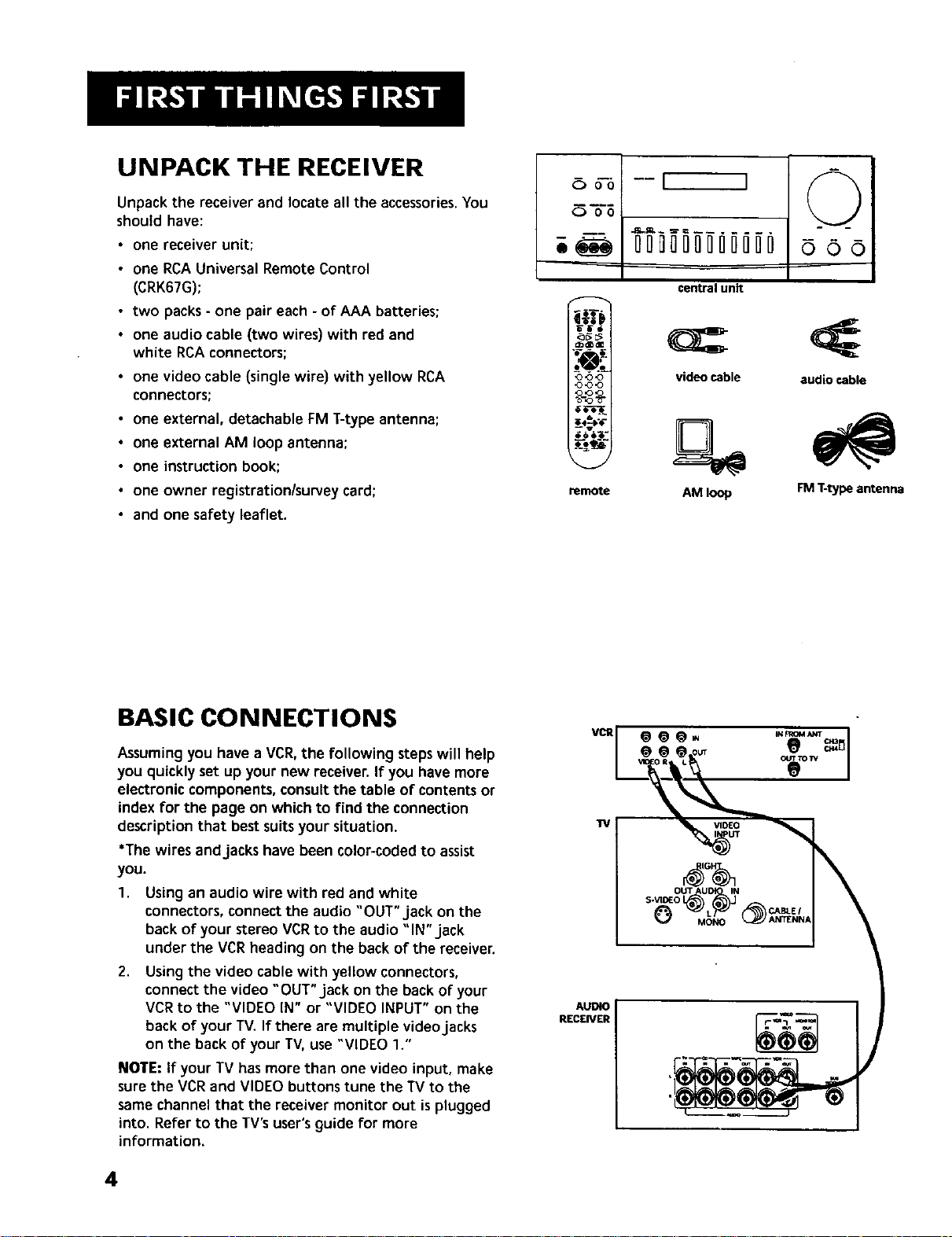
UNPACK THE RECEIVER
Unpack the receiver and locate all the accessories.You
should have:
• one receiver unit;
• one RCAUniversal Remote Control
(CRK67G);
• two packs- one pair each - of AAA batteries;
• one audio cable (two wires) with red and
white RCAconnectors;
• one video cable (single wire) with yellow RCA
connectors;
• one external, detachable FM T-type antenna;
• one external AM loop antenna;
• one instruction book;
• one owner registration/survey card;
• and one safety leaflet.
Ooo
O go
[ ]
00000[] ]00000
central unit
oo_ video cable audio cable
<3<_<3
(_ <3,o
ooeo
•
remote AM loop FM T-type antenna
BASIC CONNECTIONS
Assumingyou have a VCR,the following steps will help
you quickly set up your new receiver. If you have more
electronic components, consultthe table of contents or
index for the page on which to find the connection
description that bestsuitsyour situation.
*The wires andjacks have been color-coded to assist
you.
1.
Using an audio wire with red and white
connectors, connect the audio "OUT" jack on the
back of your stereo VCRto the audio "IN" jack
under the VCRheading on the back of the receiver.
2.
Using the video cable with yellow connectors,
connect the video "OUT"jack onthe back of your
VCRto the "VIDEO IN" or "VIDEO INPUT" on the
back of your "IV.If there are multiple video jacks
on the back of your TV, use "VIDEO 1."
NOTE: If your TV hasmore than one video input, make
surethe VCRand VIDEO buttons tune the TV to the
same channel that the receiver monitor out isplugged
into. Refer to the TV'suser'sguide for more
information.
VCR
TV
MONO
AUDIO
RECEIVER
4
Page 5
CONNECTI NG, PLACING &
BALANCING THE SPEAKERS
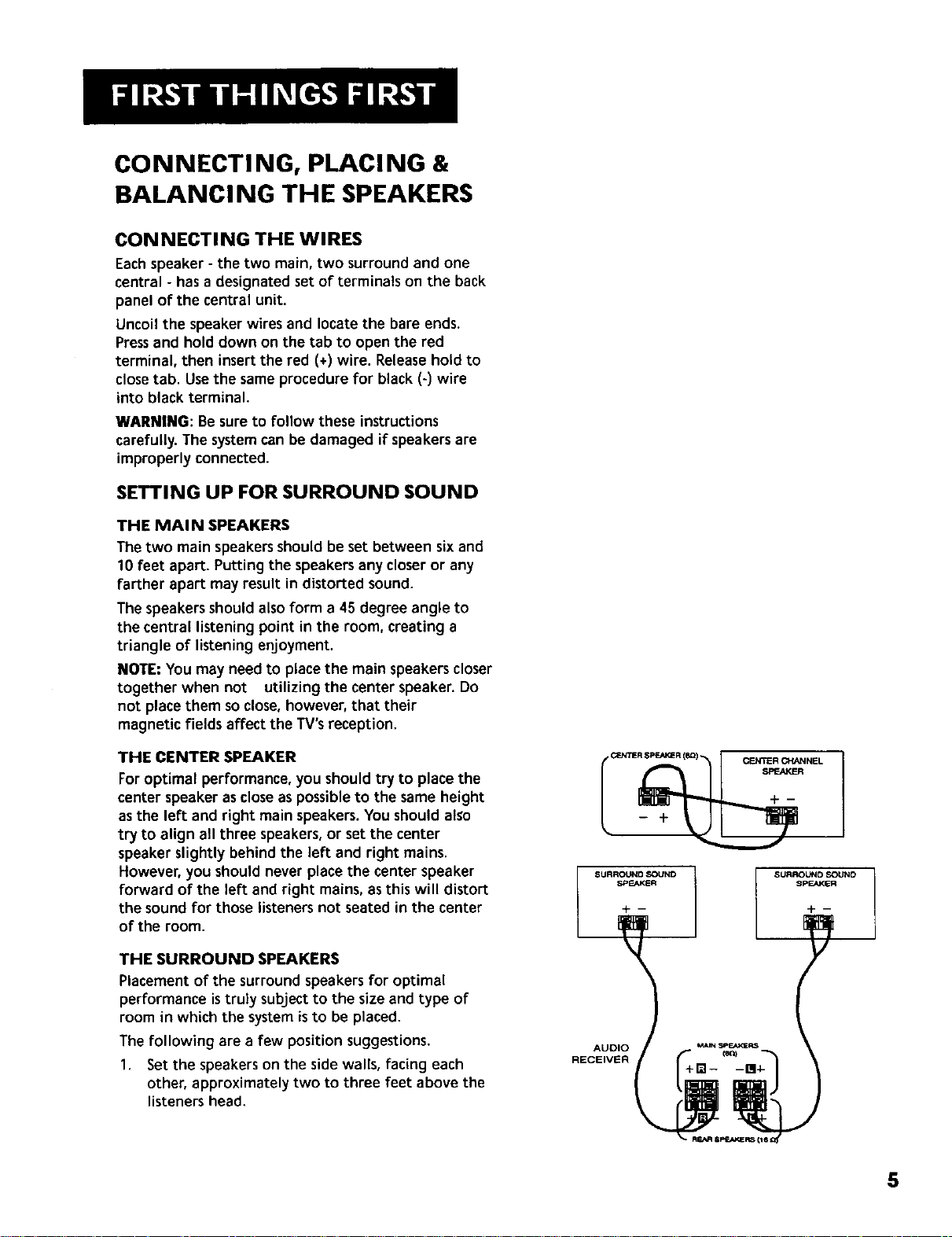
CONNECTING THE WIRES
Eachspeaker - the two main, two surround and one
central - hasa designated set of terminals on the back
panel of the central unit.
Uncoil the speaker wires and locate the bare ends.
Pressand hold down on the tab to open the red
terminal, then insert the red (+) wire. Releasehold to
closetab. Usethe same procedure for black (-) wire
into black terminal.
WARNING: Besure to follow these instructions
carefully. The systemcan be damaged if speakersare
improperly connected.
SETTING UP FOR SURROUND SOUND
THE MAIN SPEAKERS
The two main speakersshould be set between six and
10 feet apart. Putting the speakersany closeror any
farther apart may result in distorted sound.
The speakers should alsoform a 45 degree angle to
the central listening point in the room, creating a
triangle of listening enjoyment.
NOTE: You may need to place the main speakerscloser
together when not utilizing the center speaker. Do
not place them so close,however, that their
magnetic fields affect the TV'sreception.
THE CENTER SPEAKER
Foroptimal performance, you shouldtry to place the
center speaker ascloseas possibleto the same height
asthe left and right main speakers.You should also
try to align all three speakers,or set the center
speaker slightly behind the left and right mains.
However, you should never place the center speaker
forward of the left and right mains,as this will distort
the sound for those listeners not seated in the center
of the room.
THE SURROUND SPEAKERS
Placement of the surround speakersfor optimal
performance istruly subjectto the size and type of
room in which the systemisto be placed.
The following are a few position suggestions.
1. Set the speakers on the side walls, facing each
other, approximately two to three feet above the
listeners head.
CENTERSPEAKER (8Q) CENTER CHANNEL
SURROUNO SOUND
SPEAKER
-p --
SURROUND SOUND
SPEAKER
5
Page 6
2,
Aim the speakersdirectly at the two main
speakers,matching height to height. If the room is
sparselydecorated, it may be necessaryto slightly
tilt the speakersdown to increase sound
quality. If the room isdensely decorated, it may be
necessary to face the speakers toward the rear
wall or at the ceiling.
3. Mount the speakersup on the ceiling. Setthem a
few feet wide of the listeners and make sure they
are facing one another, not the floor.
Obviously there are many more possible positions, so it
may be necessary to simply experiment to find the
right balance for your situation.
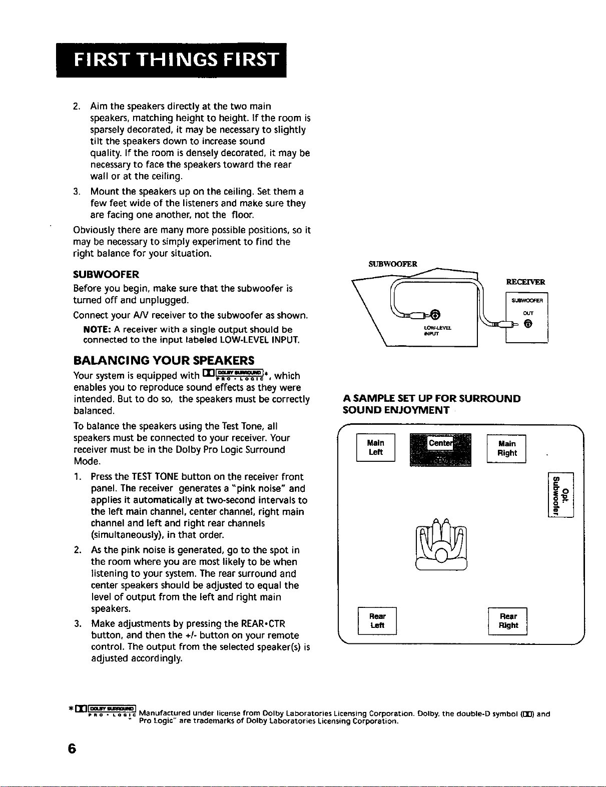
SUBWOOFER
Before you begin, make sure that the subwoofer is
turned off and unplugged.
Connect your AN receiver to the subwoofer as shown.
NOTE: A receiver with a single output should be
connected to the input labeled LOW-LEVEL INPUT.
BALANCING YOUR SPEAKERS
Yoursystemis equipped with ITI_=_., which
enables you to reproduce soundeffects as they were
intended. But to do so, the speakersmust be correctly
balanced.
To balance the speakersusingthe TestTone, all
speakersmust be connected to your receiver. Your
receiver must be in the Dolby Pro Logic Surround
Mode.
1. Pressthe TESTTONE button on the receiver front
panel. The receiver generates a "pink noise"and
applies it automatically at two-second intervals to
the left main channel, center channel right main
channel and left and right rear channels
(simultaneously), in that order.
2,
Asthe pink noise isgenerated, go to the spot in
the room where you are most likely to be when
listening to your system.The rear surround and
center speakersshould be adjusted to equal the
level of output from the left and right main
speakers.
3,
Make adjustments by pressing the REAR-CTR
button, and then the +1-button on your remote
control. The output from the selected speaker(s) is
adjusted accordingly.
SIJBWOO_I_R
A SAMPLE SET UP FOR SURROUND
SOUND ENJOYMENT
J
* fln_ Manufactured under license from Oolby Laboratories Licensing Corporation. Oolby. the double-D symbol (1_) and
" Pro Logic" are trademarks of Dolby Laboratories Licensing Corporation.
6
Page 7
Eachtime you press the + or - button on your
remote control to adjusta channel, the receiver
providesyou with two more secondsof pink noise
to that channel before moving on to the next.
4. Pressthe TESTTONE button again to end the test.
You may not need to checkor adjust these levels again
unless you move your system,rearrange the speakers,
or change your preferred seating location in the room.
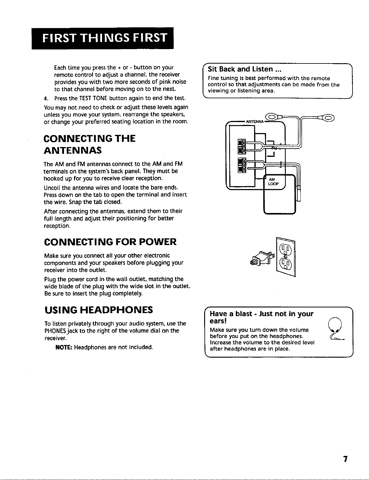
CONNECTING THE
ANTENNAS
The AM and FM antennasconnect to the AM and FM
terminals on the system'sbackpanel. Theymust be
hooked up for you to receive clear reception.
Uncoilthe antenna wires and locate the bare ends.
Pressdown on the tab to open the terminal and insert
the wire. Snapthe tab closed.
After connecting the antennas, extend them to their
full length and adjust their positioning for better
reception.
CONNECTI NG FOR POWER
rSit Back and Listen ...
Fine tuning is best performed with the remote
control so that adjustments can be made from the
viewing or listening area.
i
Make sureyou connect all your other electronic
componentsand your speakersbefore plugging your
receiver into the outlet.
Plug the power cord in the wall outlet, matching the
wide blade of the plug with the wide slot in the outlet.
Be sureto insert the plug completely.
USING HEADPHONES
To listen privately through your audio system,usethe
PHONESjack to the right of the volume dial on the
receiver.
NOTE: Headphonesare not included.
Have a blast - Just not in your
ears!
Make sure you turn down the volume
before you put on the headphones.
Increase the volume to the desired level
after headphones are in place.
7
Page 8
O oo
0 oo
ooooooo0000°0
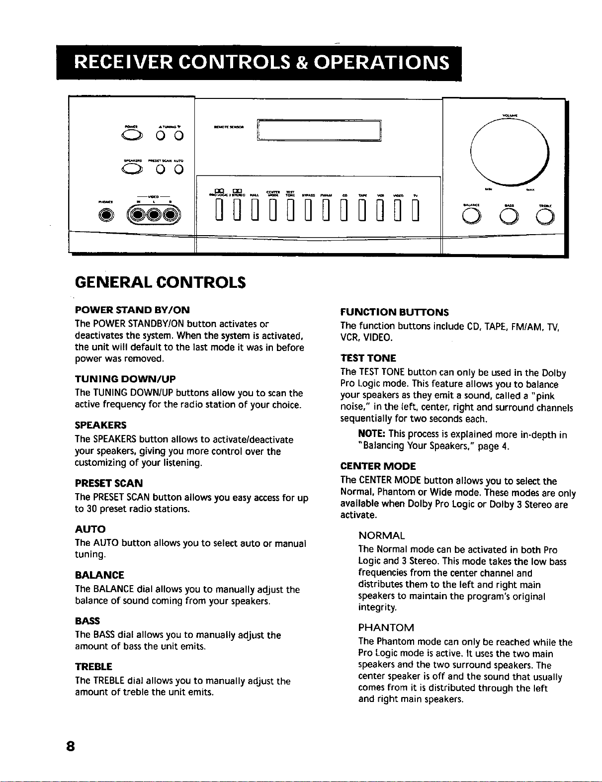
GENERAL CONTROLS
POWER STAND BY/ON
The POWERSTANDBY/ONbutton activates or
deactivates the system.When the systemis activated,
the unit will default to the lastmode it was in before
power was removed.
TUNING DOWN/UP
The TUNING DOWN/UP buttons allow you to scanthe
active frequency for the radio station of your choice.
SPEAKERS
The SPEAKERSbutton allowsto activate/deactivate
your speakers,giving you more control over the
customizingof your listening,
PRESET SCAN
The PRESETSCANbutton allows you easyaccessfor up
to 30 preset radio stations.
AUTO
The AUTO button allows you to selectauto or manual
tuning.
BALANCE
The BALANCEdial allows you to manually adjust the
balance of sound comingfrom your speakers.
BASS
The BASSdial allows you to manually adjust the
amount of bassthe unit emits.
TREBLE
The TREBLEdial allows you to manually adjustthe
amount of treble the unit emits.
©
FUNCTION BU'I-FONS
The function buttons include CD, TAPE,FM/AM, TV,
VCR,VIDEO.
TEST TONE
The TESTTONEbutton can only be used in the Dolby
Pro Logic mode. Thisfeature allows you to balance
your speakersas they emit a sound, called a "pink
noise," in the left, center, right and surroundchannels
sequentially for two secondseach.
NOTE: This process is explained more in-depth in
"Balancing Your Speakers,"page 4.
CENTER MODE
The CENTERMODE button allows you to selectthe
Normal, Phantom or Wide mode. These modes are only
available when Dolby Pro Logic or Dolby 3 Stereo are
activate.
NORMAL
The Normal mode can be activated in both Pro
Logicand 3 Stereo. This mode takes the low bass
frequencies from the center channel and
distributes them to the left and right main
speakersto maintain the program's original
integrity.
PHANTOM
The Phantom mode can only be reached while the
Pro Logic mode is active. It usesthe two main
speakers and the two surround speakers.The
center speaker is off and the sound that usually
comes from it is distributed through the left
and right main speakers.
©©
8
Page 9
WIDE
The WIDE mode can be activated in both the Pro
Logic and the 3 Stereo modes. This mode utilizes
just the three front speakers- left main, right main
and center - with all audio delivered through the
center speaker. The center speaker
will reproduce the same bass levels as the left and
right main speakers.
SURROUND MODE
Included in the SURROUNDMODE category are Dolby
Pro Logic, Dolby 3 Stereo, Hall and Bypass.
DOLBY PRO LOGIC
The Pro Logic mode usesall five speakers so the
sound envelopes the room.
DOLBY 3 STEREO
The 3 Stereo mode usesthe two main and one
center speaker.
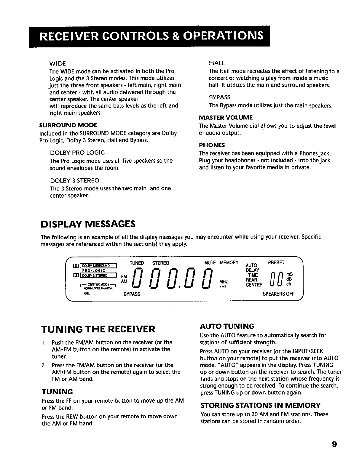
DISPLAY MESSAGES
HALL
The Hall mode recreates the effect of listening to a
concertor watching a play from inside a music
hall. It utilizes the main and surround speakers.
BYPASS
The Bypassmode utilizesjust the main speakers.
MASTER VOLUME
The Master Volume dial allows you to adjust the level
of audio output,
PHONES
The receiver has been equipped with a Phonesjack.
Plug your headphones- not included -into thejack
and li_en to your favorite mediain private.
The following isan example of all the display messagesyou may encounter while using your receiver. Specific
messages are referenced within the section(s)they apply.
TUNING THE RECEIVER
1. Push the FM/AM button on the receiver (or the
AMoFM button on the remote) to activate the
tuner.
2. Pressthe FM/AM button on the receiver (or the
AMoFM button on the remote) again to selectthe
FM or AM band.
TUNING
Pressthe FFon your remote button to move up the AM
or FM band.
Pressthe nEW button on your remote to move down
the AM or FM band.
AUTO TU N I NG
Usethe AUTO feature to automatically search for
stations of sufficient strength.
PressAUTO on your receiver (or the INPUT,SEEK
button on your remote) to put the receiver into AUTO
mode. "AUTO" appears in the display. PressTUNING
up or down button on the receiver to search. The tuner
finds and stops on the next station whose frequency is
strong enough to be received. To continue the search,
pressTUNING up or down button again.
STORING STATIONS IN MEMORY
You can store up to 30 AM and FM stations. These
stations can be stored in random order.
9
Page 10

TO STORE A STATION
1. Pressthe FM/AM button on the receiver (or the
AM.FM button on the remote) to turn on the
receiver.
2,
Select the band--FM or AM.
3.
Select the station you want to store in memory
using the methods describedabove.
4.
Pressthe MENU-SELECTbutton on the remote.
"MEMORY" blinks in the display. While
"MEMORY" is blinking, press number buttons on
the remote for the station.
Forstations 1, 2 or 3 pressO,then press1, 2, or 3.
Forstations 4 through 30, press the numbers
directly.
_fthe Memory indicator on the display turns off_
before you presetyour station selection,press
MENU-SELECTagain.
If the receiver isdisconnected from itspower
source,the preset stationsare maintained in
memory for up to 7 days.
TO PLAY A PRESET STATION
Pressthe appropriate PresetStations number. For
stations 1, 2 or 3 press O,then press1, 2, or 3. For
stations 4 through 30, press the numbers directly.
Or, press CH+ on your remote to tune to the next
preset station or CH - to tune to the previous preset
station.
PRESET SCAN N ING
Usethe PRESETSCANbutton on the receiver's front
panel to review the preset stations stored in the
tuner's memory. "PRESET"and the station's location in
memory appear in the display. The tuner automatically
scans all preset stations in order, pausing at each one
for approximately 5 seconds.
When the tuner reaches the station you want, press
PRESETSCANto stop the scanning. If the scan is not
interrupted, the tuner reviews all preset stations in
order, stopping at the point where the scan began.
J
J
USING SWAP AUDIO
Swap audio lets you change the sound from the large
picture to the small picture when you are watching TV
and using picture-in-picture (PIP)with an external
video source.
TO USE SWAP AUDIO
When you are watching TV and turn on PIP,you can
turn on another video source and swap the sound from
the large picture coming from the TV to the small
picture coming from the other video source.
1. PressTV on the remote to turn on the TV and put
the receiver in TV mode.
2. Pressthe PIP button. The empty PIPappears on the
screen.
3. Activate a video source for the PIR The picture
from the video source appears in the PIP.
4. PressTV.
S. Change to the TV channel you want to watch on
the
large screen.
6. PressSWAPAUDIO to swap the sound between the
large picture and the small picture.
7. To swap the video between the large picture and
the small picture, usethe SWAP PIP button on the
remote.
If you swap the TV picture to the PIPand the other
video source to the large picture, you may not be
able to swap
the audio.
TO CHANGE THE VIDEO SOURCE AND
SWAP THE AUDIO
Ifyouwant to changethevideosourcefor the PIPandwant to
beableto useSWAPAUDt_
1. Turn off PIP.
2. Change the video sourceto another video
component connected to the receiver.
3. PressTV to watch the "IV.
4. PressPIP.The video source appears inthe PIP.The
video from the TV appears in the large picture.
5. PressSWAPAUDIO to swap the audio as you want.
brands with the PIPfeature.
If your TV has a PIPfeature, see the TV's user's guide
I TheSwap Audio feature may not work with all TV /
for instructions for using it.
J
10
Page 11

BEFORE YOU CONNECT...
Protect components from power surges,
Connect all components before plugging any
power cordsinto the wall outlet.
Always turn off the receiver and/or components
before you connect or disconnect any cables.
Always make sure the color-coded plugs match the
color of the terminals in which they are inserted.
The connection cable plugs and jacks are color-
coded asfollows:
Speaker Terminals Red for positive (+) terminals.
Blackfor negative (-) terminals,
RCA Phono Type Terminals Red for the right (R)
channel. White for the left (L) channel.
Yellow for the video (V). Blackfor the subwoofer.
(Not Included)
Some units may be supplied with connection plugs
that are color coded red and black
instead of red and white. In this case,the black
plug takes the place of the white plug.
Contact Consumer Relations if you have questions
concerningthe connectionsor components.
POSITION CABLES CORRECTLY TO AVOID
AUDIO HUM OR INTERFERENCE
Insert all cable plugs firmly into theirjacks.
Placeaudio/video cablesto the sidesof the
receiver'sback panel instead of straight down
the middle after you connectthe components.
Try not to coil any power cablesand keep them
away from the audio/video cablesas
much as possible.
Make sure all antennas and cablesare properly
grounded. Refer to the Safety Tips sheet
packed with your receiver.
PROTECT YOUR COMPONENTS FROM OVER-
HEATING
Do not block ventilation holes in any component.
Arrange the components so that air can
circulate freely.
Do not stack componentsdirectly on top of each
other.
Allow adequate ventilation when placing your
components in a stand.
Placean amplifier near the top shelf of the stand
soheating air rising from it will not
flow around other components. If you have a
satellite receiver, you should place it on
the top shelf.
11
Page 12

CONNECTING A SATELLITE RECEIVER
Using a paired (red/white) stereo cable, a single
(yellow) video cable and two coaxial cables, connect
your new audio receiver to your satellite receiver as
shown to the right.
To watch TV programs in stereo after connection,
press TV and tune to the desired channel. To watch
satellite programming, press SAT,CABLEand tune to
the desired channel.
NOTE: Do not stackelectronic components or other
objects on top of the satellite receiver.The slotson
top of the receiver must be left uncovered to allow
proper airflow to the unit. Blockingthe airflow to the
unit could impair performance or damage your
receiver and other components. Also, do not stackthe
satellite receiver on top of a "hot component," suchas
an audio power amplifier.
COMPLIMENTARY
COMPONENT _ (_=
AUDIO
RECEIVER
TV
CONNECTING COMPLIMENTARY
COMPONENTS
Youcan connecta laserdiscplayer, secondVCRor
camcorder/videorecorder to the VIDEO connection.
Using a paired (red/white) stereo cable and two single
(yellow) video cables, connect your new audio receiver
to the complimentary component as shown to the
right.
To play laserdiscsor videos, pressthe LDoVCR2and
then play.
NOTES:When usingthis connectionfor a second VCR,
the recording option is not available.
If your camcorder or video camera does not have an
RCA-type terminal for audio/video, you can purchase
an adapter from an RCA dealer or electronic parts
store.
If the video connection is being used when you try to
hook up your video recorder or camcorder, connect
the component through any other available video
output.
lZ
Page 13

CONNECTING A COMPACT DISC
PLAYER
Using one paired (red/white) stereocable, connect
your new receiver to your compactdiscplayer as
shownto the right.
To play a CD, pressCD, put the receiver in CD mode
and pressPLAY.
NOTE: The AUDIO SOURCEconnection can be usedas
input for any stereo audio signal.
TAPE o_
DECK
AUDIO
CD
PLAYER
AUDIO
RECEIVER
CONNECTING A TAPE DECK
Usingtwo paired (redlwhite) stereo cables,connect
your new receiver to your tape deck as shown in the
diagram to the right.
To play a tape, pressTAPEand then PLAY.To record a
tape, turn on the audio sourceyou want to record
from and then press RECORDon the tape player.
CONNECTING A PASSIVE SUBWOOFER
Should you chooseto usea passivesubwoofer,the
hook up is slightly different from that of a powered
one.
If necessary,remove the vinyl covering from the ends
of the wiresand twist the wire. Pressdown and hold
the tab on the backof the speaker. Insertthe wire in
the hole, matching (+) to (+) and (-) to (-). Releasethe
tab and pull the wire gently to make sure it is securely
connected
Speaker
AN Receiver
orTelevision
+R- +L-
Speaker
I Subwoofer
13
Page 14

THE ULTIMATE CONNECTION
Shouldyou chooseto utilize your new receiver to its fullest potential by running all your audio components
through it, you will need purchaseadditional connectors. How many and what kind is purely situational.
The following is a complete description of all the_jacks on the back of the receiver and how they can be utilized
to provide greater enjoyment. Remember when connecting audio and video cablesthat, in addition to being
color-codedfor connectionaccuracy, RIGHTjacks always connectto RIGHTjacks and LEFTto LEFT,but IN,jacks
connect to OUT-jacks and OUTjacks connectto IN.
NOTE: Pleasebe advisedthe jacks are given generalized names and locations. Your TVNCR/cable box/satellite
receiver/etc, might have a different configuration of jacks with different names. The diagrams below are
outlined in the simplest possible detail.
STEP 1: CONNECTING YOUR
SATELLITE/CABLE RECEIVER
Connectthe "OUT" jack on your cable/satellite
receiver box to the "IN FROMANTENNA"jack on the
back of your VCR.
Thenconnectthe "OUT to TV"jack on the back of
your VCRto the "CABLE/ANTENNA" jack on the back
of your TV.
vc. -,=- j
@
14
AUDO
RECEIVER
VCR
STEP 2: CONNECTING
YOUR VCR TO THE RECEIVER
Using video cables,connect the video VCR"IN" and
"OUT"jacks on the back of your receiver to the "OUT"
and "IN" videojecks on the back of your VCR.
Using audio cables,connect the right and left "IN" and
"OUT" audio VCR,jacks on the back of your receiver to
the right and left "IN" and "OUT',jacks on the back of
your VCR.
Page 15

STEP 3: CONNECTING YOUR RECEIVER AUDIO
TO YOUR TV RECEIVER
Using audio cables, connect the left and right "OUT"
audiojecks on the back of your TV to the TV audio
jacks on the back of your receiver,
CABLE
TV
AUD0
RECEIVER
WHEN YOU'RE ALL CONNECTED ....
When you're all finished connecting your basic
componentstogether, you'll have quite a messof wires
backthere.
Add to this a tape deck, laserdisc player and second
VCR and you can imagine the confusion.Just be
patient and follow each component'suser's guide and
you'll be rewarded with excellent audio and hours of
top quality entertainment.
15
Page 16

BATTERY INSTALLATION
The remote control operates on four batteries,
included with your system. Install them before
attempting to operate the remote.
1. Slide the battery compartment cover off the back
of the remote.
2. Insert 4 AAA batteries, matching the + and - ends
of each battery with the symbols in the
compartment.
3'. Replace the cover.
BASIC CONTROLS
AM'FM TAPE CD
REV PLAY FWD
t>
REC STOP PAUSE
GULDE'R_M C_+ SKIP
;e.
MUTE c_- GO BACK_DI
Your remote control is capable of operating most RCA
audio and video equipment. To usethe remote control
effectively, always aim it directly at your receiver.
POWER Turnsthe AMIFM receiver off with two
presses. If you have multiple componentsturned on
and not the AM/FM receiver,pressingPOWERonce
turns off the lastcomponent turned on. Pressing
POWERagain quicklyturns off all other components.
VOL UP and DOWN Increasesor decreasesthe
volume.
MUTE Turnsoff the receiver's sound. Pressagain to
restore the sound.
(
RECEIVER CONTROLS )
AM.FM Activatesthe tuner and toggles between the
AM band and the FM band.
CTR MODE Changes the Center mode when using
Dolby Pro Logic Surround or Dolby 3 Stereo surround
modes. Pressonce and the current mode appears. Press
again to change the mode.
40 60
INFO CL_SET'REEELAY
0000
CE
MENU A TV MENU
SELECT I_
PIP -- + SNAP PIP
PLAYLIST _ CTR MODE
AUDIO
16
Page 17

DELAYICH CTRL Selects the amount of Surround
Sound delay between the main and rear speakers.
Choose from 15, 20 or 30 milliseconds. Press once and
the current setting appears. Press again to change the
setting.
- On some RCATV models, used to adjust menu
controls.
ANTENNA Changes the antenna input.
CH + and CH - Tunes the TV channel up and down.
SURROUND Lets you selecta Surround Mode: Dolby
Pro LogicSurround, Dolby 3 Stereo or Hall. Pressonce
to turn on the surroundmode last selected. Press
again to change
the mode.
SWAP AUDIO Swapsthe audio only from the large
picture to the small picture when you are watching TV
and using picture-in-picture (PIP),
_ SURROUND SOUND LEVEL CONTROL$_
+ Increasesthe volume in rear and center speakers.
- Decreasesthe volume in rear and center speaker.
BYPASS Turns on Bypassmode, which cancelsall
Surround sound modes. Sound is generated without
effects.
REAR.CTR LEVEL AdJusts the balance level of the
rear and center speakers. Pressoncefor Center. Press
again for Rear.
RECEIVERFI'UNER CONTROLS >
CH + and CH - Tunesthe receiver to the next or
previous preset station stored in the receiver's
memory.
Lets you manually move up the AM/FM band.
INPUT.SEEK Selects auto tuning or manual tuning
mode.
MENU SELECT Stores the selected station in the
receiver's memory.
Number Buttons Let you enter numbers when
needed.
REV Lets you manually move down the AM/FM band.
_TV CONTROLS
+ On some RCATV models, usedto adjust menu
controls.
CLEAR Removes any menu from the screen.
DELAYICH CTRL In some RCA TV models, lets you
control the channel that appears in the PiP window or
the main screen in P(P mode.
GO BACK.DISC Returnsto the previous channel,
GUIDE.RDM Forsome models, brings up 12 small
pictures (previews of the next 12 channels in the
channel list). Pressagain to turn off channel guide.
INFO Displayschannel information.
INPUT.SEEK For some TV models, toggles through the
available input sources.
MENU SELECT For some models, storeschannelsin the
TV's memory.
MOVE arrows In somemodels, when using PIP,moves
the small picture to another corner of the screen.Also,
used for menu navigation in some TV models.
Number Buttons Let you enter channel numbers and
time settings when needed.
PIP Turnson and off picture-in-picture on most RCA
TV modelswith PIP.
POWER Turnsthe TV off.
RESET.REP Returns picture quality controlsto their
original settings.
SKIP To change channels, press once. The TV will wait
30 secondsbefore returning to the original channel.
Pressrepeatedly to increasethe time.
SWAP PIP Swapsthe main picture in the PIPwindow.
13/ Turns on the TV and puts the remote in TV mode.
TV MENU Displaysthe TV'son-screen menus.
C
VCR CONTROLS >
CH +and CH - Tunesto the next or previouschannel
when watching TV through the VCR.
17
Page 18

CLEAR Resets the tape counter and corrects entries
when programming the menus.
FWD Fast forwards a tape. Also, searches forward
while a tape is playing.
PLAY Plays the DVD.
PLAYLIST For some DVD models, if programmed,
programs the DVD player to playback tracks in a
certain order.
GO BACK,DISC Returns to the previous channel.
INFO Displays channel, time and counter information
on the screen.
INPUT,SEEK For some VCR models, selects line input
or tuner.
LD.VCR2 For some VCR models, if programmed, turns
on a second VCR and puts the remote in VCR2 mode.
MENU SELECT Displays the on-screen
programming menus.
Number Buttons Let you enter numbers when
needed.
PAUSE Pauses a tape.
PLAY Plays a tape.
POWER Turns the VCR off.
REC Records a tape.
REV Rewinds a tape. Also, searches backward while a
tape is playing.
SKIP To change channels, press once. The TV will wait
30 seconds before returning to the original channel.
Press repeatedly to increase the time.
STOP Stops a tape.
VCR Turns on the VCR and puts the remote in VCR
mode.
POWER Turnsthe DVDplayer off.
REW Scansbackward on the DVD.
STOP Stopsthe DVD
_ SATELLITE RECEIVER CONTROLS "_
ANTENNA Togglesbetween antenna input and
satellite receiver input.
CH + and CH - Tunes to the next or previous channel
when watching TV through the satellite system. Steps
through the pages in the guide if in guide mode.
GUIDE.RDM Displaysthe guide on the screen.
INFO Displayssatellite header on screen.When in the
guide, lets you selecta program. Lets you select an
option in a menu.
MOVE arrows Letsyou point to different on-screen
menu items.
Number Buttons Let you enter numbers when
needed.
POWER Turnsthe RCADSS*receiver off.
_CD PLAYER CONTROLS
CD Turnson the CD player and putsthe remote in CD
mode.
CLEAR Clears an entry when programming the CD
player.
DVD PLAYER CONTROLS _)
CH + and CH - Changes to the next higher or lower
track on DVD.
DVD Turns on the DVD player, and puts the remote in
DVD mode.
FWD Scans forward on the DVD.
Number Buttons Let you change to a specific track.
PAUSE Pausesthe DVD.
18
FWD Moves forward through the CD one track at a
time.
GO BACK-DISC Selectsa disc to be played. PressGO
BACK.DISC and then the CD number using the number
buttons.
GUIDE.RDM Activates the Random function, which
plays a random selection of tracks from one or all CDs.
INFO In someCD models, lets you switch between the
number track information and time information.
Page 19

MENU SELECT Programsthe CD changerto play up
to 32 tracks in any order you choose.
Number Buttons Let you enter numbers when
needed.
PAUSE Pauses the CD.
PLAYLIST For some laserdisc models, if programmed,
programsto playbackchapters on laserdiscin a certain
order.
POWER Turnsthe laserdiscplayer off.
REV Scansbackward on the laserdisc.
PLAY Playsthe CD.
RESET.REP Repeats a track, a CD or an entire
program. Pressonce to repeat the currently playing
track, twice for the CD or program, and three times to
turn the function off.
REV Moves backward through the CD one track at a
time.
STOP Stops the CD from playing.
TAPE DECK CONTROLS
FWD Fastforwards the tape.
Number Buttons Let you enter numberswhen
needed.
PAUSE Pausesthe tape.
PLAY Playsthe tape.
POWER Turnsthe tape player off.
REV Rewindsthe tape.
TAPE Turnson the tape player and putsthe remote in
tape player mode.
C
LASERDISC PLAYER CONTROLS
CH + and CH - Changes to the next higher or lower
chapter on the laserdisc.
FWD Scans forward on the laserdisc.
LD.VCR2 For some laserdisc models, if programmed,
turns on the laserdisc player and puts the remote in
laserdisc mode.
Number Buttons Let you changeto aspecific
chapter.
STOP Stops the laserdisc.
PROGRAMMING THE
UN IVERSAL REMOTE
You can program the remote to control most brands of
remote controllable TVs, VCRs and cable boxes. If you
have an RCA, GE or ProScan VCR, you may not need to
program the remote at all. Other manufacturer's
brands need to be programmed.
PROGRAMMING THE REMOTE
TO CONTROL A TV
To determine whether you need to program the
remote, turn on the TV, point the remote at the TV's
remote sensor and pressTV. Then, press the POWER,or
CH + or CH - button to see if the TV responds to the
remote commands. If not, you need to program the
remote.
Follow these stepsto program your remote to control
your TV:
1. Turn on the TV.
2. Lookup your TV brand and code number(s) in the
code list on the next page or on the code sheet
packed with your remote.
3.
Pressand hold the TV button on the remote.
4.
Enter the three-digit code from the code list.
5.
Releasethe TV button, then pressPOWERto see if
the TV responds to the remote commands.If not,
try pressing TV
then POWER.
6.
Repeat steps3 through 5 using the next code listed
for your TV brand until the TV responds to the
remote commands.
PAUSE Pauses the laserdisc.
PLAY Playsthe laserdisc.
buttons with another component, refer to the
I If you have questions about the useof the remote |
components user sguide.
19 ¸
J
Page 20

PROGRAMMING THE REMOTE
TO CONTROL A VCR
To determine whether you need to program the
remote, turn on the VCR, point the remote at the VCR's
remote sensor, and press VCR. Then, pressthe POWER
orCH + orCH - buttonto see iftheVCR respondsto
the remotecommands. Ifnot,you needtoprogram
the remote.
Follow these steps to program your remote to control
your VCR:
1. Turn on the VCR.
2. Look up your VCRbrand and code number(s)in the
code list on the next page or on the code sheet
packed with your remote.
3. Pressand hold the VCRbutton on
the remote.
4.
Enter the three-digit codefrom the code list,
5.
Releasethe VCRbutton, then press POWERto see
if the VCRresponds to the remote commands. If
not,trypressingVCR
thenPOWER.
6. Repeat steps3 through 5 using the next code listed
for your VCR brand until the VCRresponds to the
remote commands.
PROGRAMMING THE REMOTE TO
CONTROL AN AUDIO COMPONENT
To program the remote for a remote-controllable
audio component, point the remote at the component
and pressthe correct component button: CD for a CD
player, TAPEfor a tape player, etc. Then, pressPOWER
or CH + or CH -. If the component doesn't respond,
the remote needs to be programmed. Usethe codes in
the code list on the next page or on the sheet packed
with your remote.
Follow these stepsto program your remote to control
your audio component:
1. Turn on the component to be programmed.
2. Look up the brand and correspondingcode
number in the code list on page 28 or on the code
sheet packed with your remote.
3. Pressand hold the component button on
the remote.
4. Enter the three-digit code from the code list.
S,
Release the component button, then pressPOWER
to see if the component responds to the remote
commands. If it doesn't, try pressing the
component button, then POWERagain.
6. Repeat steps 3 through 5 using the next code listed
for the brand of your component until the
component responds to the remote commands.
PROGRAMMING THE REMOTE
TO CONTROL A CABLE BOX
Refer to the cable box connection page or contact your
cable company to hook up your cable box. You may be
able to program the remote for your remote
controllable cable box. Usethe codes in the code list
on page 28 or on the sheet packed with your remote.
1, Turn on the cable box.
2. Look up the cable box brand and its code
number(s) in the code list on the next page or on
thecodesheetpackedwiththe remote.
3. Pressand hold the SAT.CABLE button on
the remote.
4. Enterthe three-digit codefrom the code list.
,
Releasethe SAT.CABLEbutton, then pressPOWER
or CH + or CH - to see if the cable box responds to
the remote commands. If not, try pressing
SAT.CABLE,then POWERagain to see if the cable
box responds.
6. Repeat steps 3 through 5 using the next code listed
for the brand of your cable box until the cable box
responds to the remote commands.
PROGRAMMING THE REMOTE
TO CONTROL A LASERDISC PLAYER
You may be able to program your remote to control a
laserdiscplayer. Usethe codesshown to the right or on
the sheet packed with your remote.
Follow these stepsto program your remote to control
your laserdisc player:
1. Turn on the laserdisc player.
2. Look up the brand and its code number(s) in the
code list.
3. Pressand hold the LD-VCR2 button on the remote.
4. Enter the three-digit code from the code list.
Pioneer .................................033,037
ProScan ................................033,037
LASERDISC PLAYER CODES 1
RCA.......................................033,037
20
Page 21

PROGRAMMI NG THE REMOTE
TO CONTROL A DVD PLAYER
The remote is preprogrammed to control a RCA DVD
player. A few of the remote buttons used with a DVD
player are shown below. You may want to experiment
with other buttons on the remote to see if they work
with your DVD player.
Receiver Remote (works like) DVD Remote
INFO INFO
GO BACK GO BACK
CLEAR CLEAR
MENU SELECT MENU SELECT
MOVE Arrows ARROWS
PLAYLIST PLAYLIST
ENTER ENTER
PROGRAMMING THE REMOTE
TO CONTROL A SATELLITE RECEIVER
1. Turn on the satellite receiver.
2. Look up the satellite receiver brand and
corresponding code number(s) in the code list on
the right.
3. Pressand hold the SAT.CABLEbutton on
the remote.
4. Enter the three-digit code from the code list.
5. Releasethe SAT-CABLEbutton, then press POWER
or CH + or CH - to see if the receiver responds to
the remote's commands. If it doesn't, try pressing
SAT.CABLE,then POWERagain.
6. Repeat steps 3 through 5 using the next codelisted
for the brand of your receiver until the receiver
responds to the remote commands.
PROGRAMMING THE REMOTE
TO CONTROL AN RCA BRAND DSS®
RECEIVER
The remote is preprogrammed to control the RCA
brand DSSereceiver. A few of the remote buttons used
with the RCA brand DSS° receiver are shown below.
You may want to experiment with other buttons on
the remote to see if they work with your receiver.
Receiver Remote (works like) RCA brand DSSe
Remote
INFO SELECT/DISPLAY
GO BACK PREV CH
ANTENNA TV/SAT
CLEAR CLEAR
MENU/SELECT MENU
MOVE ARROWS ARROWS
fr
Thisremote may not operate all models of the
brands shown.
If a battery is removed from the battery
compartment of the remote control, all control key
functions will return to the original mode.
To program the LD-VCR2 button to control a second
VCR, follow these steps but use the LD-VCR2 button
instead of the VCR button.
The buttons on the remote may not work on all
other brands of components. Experiment with the
remote and your components to see which buttons
work.
DSS"isa registered trademark of DIRECTV,INC., a unit of GM HughesElectronics.
21
Page 22

f
Admiral ........................................ 005
Amtron ......................................... 064
Akai ...................................... 002, 103
A-Mark ......................................... 102
Anam .................................... 104, 105
Anam National .................... 038, 106
AOC .................... 011,019, 027. 088,
107
Bell & Howell .............................. 005
Candle ......................... 011,027,033
Citizen ................. 011,027, 033, 064
Colortyme ................... 011,027, 084
Concerto .............................. 011,027
Contec/Cony ......036, 037, 040, 042,
064
Craig ............................................. 064
Curtis Mathes ............ 000, 011,015,
027, 037
CXC ............................................... 064
Daewoo ............... 011,019, 027, 112
Daytron ................................ 011,027
Dimensia ...................................... 000
Electrohome ...... 006, 011. 014. 027,
038, 061,068
Emerson ............. 011,026, 027, 028,
029, 030, 031,032, 037,042, 053,
064, 065, 067, 075, 076, 078, 079,
094. 095, 096
Envision ................................ 011. 027
Fisher ................... 017, 021,039, 041
Funai ............................................. 064
GE ....................... 000, 008, 009, 011,
012, 027, 038, 068, 086, 089, 091
Goldstar ............. 003, 004, 006, 011,
019, 027, 037, 050
Hallmark .............................. 011,027
Hitachi ................ 009, 011,027,036,
037, 040, 047, 048, 063, 080, 094,
097, 098
Infinity ......................................... 013
JBL................................................. 013
JC Penney ........... 000, 008, 011,019,
027,040, 068, 077. 086,088
Jensen .................................. 011,027
JVC...................... 012,024, 036, 037,
040,048,051,074
Kawasho ..................... 002, 011, 027
Kenwood ............ 006,011,014,027
Kloss Novabeam ................. 035,043
KTV ............................................... 078
Loewe ........................................... 013
Luxman ................................ 011,027
LXl ....................... 000,013,018, 021,
023. 054
Magnavox .......... 006,007.010,011,
013, 016,027,033, 035,043, 049,
066,087, 089
Marants ........................................ 013
Marantz .............. 011,013,027, 069
Memorex ...................................... 005
MGA ................... 006, 011,014, 019,
022,027, 041,056, 061,068
Mitsubishi .......... 006, 011,014, 019,
022,027, 041,055, 056, 061,068
MTC ............................. 011,019,027
Multivision ................................... 081
NAD ...................................... 018, 023
NEC ..................... 011,014, 019, 027,
038,084
Panasonic...012,013, 038,086,111
Philco .................. 006,007, 010, 011,
013,016,019. 027, 033,035,037,
038,043, 087,089
Philips ................. 002, 006,007,010,
011,013,016, 033, 035,037,038,
043, 066,073
Pioneer ............... 011,027,045,062,
093
Po_land .............. 011,019,027,037
ProScan ........................................ 000
Proton ................. 011,027,037,072
Quasar ......................... 012,038,092
Radio Shack ....... 000, 021,025, 036,
037,059,064,078
RCA ..................... 000, 006,011,019,
027, 034, 038,044,046,088,100,
101,109
Realistic ........................................ 021
Sampo .................................. 011,027
Samsung ............. 006,011,014,015,
019,027,036,037, 077,110
Sanyo..017,021,039,056,057,058
Scott ............................ 028, 037,064
Sears ................... 000, 006,011,014,
017, 018,021,023,027,039,040,
041,051,071,083, 095
Sharp .................. 011,020, 025,027,
037,052,053,059,060,108
Signature ............................. 005, 094
Sony .............................................. 002
Soundesign ................. 011,027,033
Sylvania .............. 006,007,010,011,
013,016,027,033,035,043,049,
066,087, 089
Symphonic ........................... 064,076
Tatung .......................................... 038
Technics ........................................ 012
Techwood ............................ 011,027
Teknika ............... 011,019, 027,033,
036,037,040,066
Telecaption .................................. 090
TMK ...................................... 011,027
Toshiba ............... 018, 021,023, 040,
071.077,085,090
Universal .............................. 008,009
Victor ............................................ 051
Vidtech ................................. 019, 027
Wards ................. 000,005,006,007,
008,009,010.011,013,019,025,
027,028,035,043,059,066,076,
082, 089
Yamaha ............... 006,014,019,027
Zenith ................................... 001,099
22
Page 23

Admiral ....................................... 006
Aiwa ............................................ 015
Akai .................. 003, 017,022, 023,
063, 066
Audio Dynamics ................. 014, 016
Bell & Howell ............................. 002
Broksonic .................................... 010
Candle .............. 007, 009, 013, 044,
045, 046, 052
Canon .................................. 008, 053
Capehart ..................................... 001
Citizen .............. 007, 009, 013, 044,
045, 046, 052
Colortyme ................................... 014
Craig .................................... 007, 012
Curtis Mathes .. 000, 007,008, 014,
015, 044,046, 053, 064,067
Daewoo .............. 013, 045, 052, 076
dbx ....................................... 014, 016
Dimensia ..................................... 000
Dynatech ..................................... 015
Electrohome ............................... 027
Emerson ........... 008, 009, 010, 013,
015, 020, 023, 027, 034, 041,
042, 047, 049, 057, 062, 065,
067, 068, 070
Fisher ................ 002, 012, 018, 019,
043, 048, 058
Funai ............................................ 015
GE ..................... 000, 007,008, 032,
037, 053
Goldstar ............. 009, 014, 046, 060
Harman Kardon ......................... 014
Hitachi ................ 005, 015, 035, 036
Instant Replay ............................ 008
JCL................................................ 008
JC Penney ......... 002, 005, 007, 008,
014, 016, 030, 035, 051,053
JVC .................... 002. 014. 016. 030.
046. 074
Kenwood ......... 002. 014, 016, 030.
044. 046
KLH .............................................. 073
Lloyd's ......................................... 015
Logik ............................................ 031
Magnavox .......... 006. 029, 053, 056
Marantz ........... 002, 008, 014. 016,
029, 030. 044. 046, 061
Marta ........................................... 009
MEI ............................................... 008
Memorex ............ 008, 009, 012, 015
MGA .................................... 004, 027
Midland ....................................... 032
Minolta ............................... 005, 035
Mitsubishi ........ 004, 005, 027, 035,
040
Montgomery Ward .................... 006
MTC ..................................... 007, 015
Multitech ........... 007,015, 031,032
NEC ................... 002, 014, 016, 030,
044, 046, 059, 061,064
Panasonic ........... 008, 053, 075, 077
Pentax ........................ 005, 035, 044
Pentex Research + ..................... 046
Philco .................. 008, 029, 053, 056
Philips .................................. 008, 029
Pioneer ....... :............... 005, 016, 050
Portland ..................... 044, 045, 052
ProScan ....................................... 000
Quartz ......................................... 002
Quasar ................................. 008, 053
RCA ................... 000, 005, 007, 008,
028, 035, 037, 054,069
Radio Shack/Realistic ...... 002, 006.
008. 009, 012, 015. 019, 027. 043.
O53
5amsung ........... 007,013,022,032,
042
Sansui .................................. 016, 071
Sanyo ................................... 002, 012
Scott ......:.......... 004, 013,041,049,
068
Sears ................. 002, 005,009,012,
018,019,035,043,048
Sharp ................ 006,024,027,039,
045
5hintom .............. 017, 026, 031,055
Signature .................................... 015
Sony ............................ 017,026, 038
Sylvania ............ 008, 015,029, 053,
056
Symphonic .................................. 015
Tandy ................................... 002, 015
Tashiko ........................................ 009
Tatung ......................................... 030
Teac ............................ 015, 030, 069
Technics ....................................... 008
Teknika ............... 008, 009, 015, 021
TMK ............................................. 067
Toshiba ............. 005, 013, 019, 048,
049
Totevision ........................... 007, 009
Unitech ........................................ 007
Vector Research ........ 014, 016, 044
Victor ........................................... 016
Video Concepts ......... 014, 016,044
Videosonic .................................. 007
Wards ............... 005, 006, 007, 008,
009,012, 013, 015, 025,027, 031,
035
Yamaha ............ 002,014,016,030,
046
Zenith ................. 011,017,026, 072
23
Page 24

AUDIO CODES
ads: AMP
Aiwa: CD
Akai: AMP
Denon: CD
Dynamic Bass: AM/FM
Emerson: CD
Fisher AMP
Hitachi: CD
JVC: AMP
Kenwood: AMP
Kyocera: AMP
Lotte (NEC): AMP
Magnavox: AMP
Marantz: AMP
Mitsubishi: AMP
Nakamichi: AMP
Onkyo: AM/FM
Panasonis: AMP
Philip: AMP
pioneer: AMP
RCA: AMP
Realistic: CD
Sansui: CD
Scott: CD
Sherwood: AMP
Sony: AMP
Teac: AMP
Technics: AM/FM
Yamaha: AMP
CD
TAPE
PHONO
CD
AM/FM
CD
TAPE
AUX
AM/FM
CD
TAPE
PHONO
AMrFM
CD
AM/FM
CD
AMJFM
CD
TAPE
PHONO
AM/FM
CD
TAPE
AM/FM
CD
AM/FM
CD
TAPE
AM/FM
CD
TAPE
PHONO
AUX
TAPE
AM/FM
CD
TAPE
PHONO
CD
CD
TAPE
OOl
O6O
002, 008
057
O29
025
026, 027
O28
O66
023
067
063
016,058
030,035
032
033,034
031
017,074
074
067,070, 077
071,072
073
OO9
O75
O65
O65
061
022,076
O76
O68
015,059
O59
O20
082
078
030,081
079
012
038
036,083
037
062
O62
061
014
042
O39
040,041
024
OO3
007,043, 044
OO6
OO5
004,054
063,066
O45
O66
055,056
011,013
021
049
o46
048,053
o47
010
069
052
05o
051
018, 019
f
REMOTE CONTROLLABLE
CABLE BOX CODES
ABC 022, 046, 053, 054
Anvision 007, 008
Cablestar 007, 008
Diamond 056
Eagle 007, 008
Eastem Intematlonal 002
General Instrument 046
GI 400 004, 005,015,023,
024, 025,030, 036
Hamlin 003, 012, 013, 034, 048
Hitachi 037, 043, 046
Jerrold 004, 005, 015, 023,
024, 025,030, 036, 045,
046, 047, 062, 065
Macom 037, 043
Magnavox 007, 008, 019, 021,
026, 028, 029, 032, 033,
040, 041
NSC 009
Oak 001,016, 038
Oak Sigma 016
Panasonic 003, 027, 039, 061
Phitips 007, 008, 019, 021,026,
028, 029, 032, 033, 040,
041
Pioneer 018, 020, 044
Randtek 007, 008
RCA 000, 027
Regal 003, 012, 013
Regency 002, 033
Samsung 044
Scientific Atlanta 003, 022, 035, 063, 064
Signature 046
Sprucer 027
Starcom 046
Stargate 2000 058
Sylvania 011,059
Teknika 006
Texscan 010, 011,059
Tocom 017, 021,049, 050, 055
Unika 031,032, 041
Universal 051,052, 060
Viewstar 007, 008, 019, 021,026,
028, 029, 032, 033, 040,
041
Warner Amex 044
Zenith 014, 042, 057, 061
/,
24
Page 25

TROUBLESHOOTING TIPS
RECEIVER/TUNER OPERATION
STEREO indicator is off.
• Adjust the antenna.
• The signal is too weak. Connect an external
antenna.
• The signal is Mono.
Severe hum or noise.
• The signal istoo weak. Connect an externat
antenna.
• Adjust the antenna,
REMOTE CONTROL OPERATION
The remote control does not operate the unit,
• Another function isselected on the remote. Press
the correct function button,
• No batteries installed, (Included with your system)
Install the batteries before attempting to operate
the remote. Be sure to match the + and - ends of
each battery to the symbols shown in the remote
battery compartment.
• The batteries are exhausted. Replace all batteries.
• The remote is not pointed at the remote control
sensor on the main unit or there is an obstacle
between the remote and the main unit.
• The remote control is too far from the main unit.
• Move closer.
GENERAL
No audio,
• Make sure the MUTE indicator on the front panel
isoff.
• Make sure the speakers are turned on.
• Check the connections.
• Check the power cord connection.
NO audio from one channel.
• Adjust the balance control,
• Check the speaker wire connection or connecting
cable, Noise when the TV isturned on,
• The TV istoo close to the audio system,
Specific instruments sound displaced.
• Check the connection between the receiver and
the speakers,
The sound does not match the video,
• Press the function button for the video source,
CLEANING THE EXTERIOR
Disconnect the system from AC power before
cleaning the exterior of the system with a soft dust
cloth.
EQUIPMENT SPECIFICATIONS
AMPLIFIER SECTION
Left/Center/Right (at 8 EZ):
RV-9968 20 watts/20 watts/20 watts
RV-9978 50 watts/50 watts/50 watts
0.9% THD @ 1 KHz
Rear Surround (at 16 _2):
RV-9968 10 watts/10 watts
RV-9978 25 watts/25 watts
1.0% THD @ 1 KHz
Muting Attenuation: 50dB
Frequency Response 40-20 kHz +/- 3 dB
VIDEO SECTION
Input (Sensitivity/impedance): 1 Vp-p/75 Q
Output (Level/Impedanse): 1 Vp-p/75
Frequency Response: 10 Hz to 6MHz at +/- 3 dB
Signal to Noise Ratio: 40 dB
Crosstalk o 3.S8 MHz: 40 dB
AM TUNER SECTION
Frequency Response:
Usable Sensitivity:
Signal to Noise :
Image Ratio:
IF Rejection:
FM TUNER SECTION
Frequency Response:
Quieting
Signal to Noise:
Image Ratio:
IF Rejection:
80 Hz -2 kHz +/~ 6 dB
800uV/m@ S/NZOdB
38 dB
27 dB @ 1000 kHz
35 dB
40 Hz-15 kHz +/- 3 dB
24 dBu
60 dB (stereo)/65 dB(mono)
40 dB
50 dB
Specifications are based on nominal measurements.
25
Page 26

SYMBOLS
+ button 16, 17
- button 16, 17
A
Accessories included 4
AMoFM button 9, 16
ANTENNA button 17
Audio codes 24
AUDIO SWAP button 16
B
BAND button 9
Basic controls on the remote 16
BYPASSbutton 16
INPUT.SEEK button 17
L
Leserdisc codes 20
i
MENU/PROGRAM button 17, 18
MOVE arrows 17
MUTE button 16, 17
N
Number buttons 17, 18
P
$
SKIPbutton 17
Speaker terminals, matching 11
Speakers 5
Specifications, equipment 25
Stations
preset 9
storing in memory 9, 10
STOP button 17, 18
Storing stations in memory 10
Subwoofer, connecting 11
SURROUND button 16, 17
Surround sound level controls 16
SWAP PIPbutton 17
3"
C
Cable box 20
Care and maintenance 25
Cleaning 25
CH CTRL/DELAY button 17
CHAN up and down buttons 17
CLEAR button 17
Connecting components 11
CTRMODE button 16
D
DISPLAY button 17
E
Equipment specifications 25
F
FFbutton 17, 18
G
GUIDEoRDM button 18
H
Headphones 7
P.SCAN button 8
PAUSEbutton 17, 18, 19
PIPbutton 16, 17
PLAY button 16, 18, 19
POWER button 16, 17, 18, 19
Preset stations
playing 10
setting 10
PREVCH.DISC button 16, 17, 18
PROGRAM button 9
Programming the remote to control
a cable box 20
Laserdisc 20
RCA DSS® Receiver 20
satellite receiver 20
TV 19, 20
VCR 20
R
RCA DSS® Receiver codes 21
REAR,CTR Level button 17
RECbutton 17
Receiver controls on the remote 16
Remote
Basic controls 16
programming 20
Remote control buttons 16
RESET,,REPbutton 17
REV button 17, 18
Troubleshooting tips 25
Tuning the receiver 9
TV controls 17
TV button 17
TV MENU button 17
V
VCR1 button 17, 18
VCR2.LD button 17, 18
VOL up and down buttons
16, 17, 18
26
Page 27

What your warranty covers:
Any defect in materials or workmanship.
For how long after your purchase:
One year. (The warranty period for rental units beginswith the first rental or 45 daysfrom date of
shipment to the rental firm, whichever comesfirst.)
What we will do:
Provide you with a new, or at our option, a refurbished unit.
The exchange unit is under warranty for the remainder of the original product's warranty period.
How to make a warranty claim:
Properly pack your unit. Includeany cables,etc., which were originally provided with the product. We
recommend using the original carton and packing materials.
Include in the package evidence of purchase date suchas the bill of sale. Also print your name and
address and a description of the defect. Send standard UPSor itsequivalent to:
Thoms( Censu Electzomcs
Product Exd a ge
11721B Alameda Ave.
Socorro, Texas 79927
Pay any charges billed to you by the ExchangeCenter for servicenot covered by the warranty.
Insure your shipment in caseof loss or damage. Thomson accepts no liability in caseof damage or loss.
A new or refurbished unit will be shippedto you prepaid freight.
What your warranty does not cover:
Customer instruction. (Your Owner's Manual provides information regarding operating instructions and
user controls. For additional information, ask your dealer.)
Installation and set-up serviceadjustments.
Batteries.
Damage from misuse or neglect.
Products which have been modified or incorporated into other products.
Products purchased or servicedoutside the USA.
Acts of God, suchasbut not limited to lighttling damage.
Product Registration:
Pleasecomplete and mail the ProductRegistration Card packedwith your unit. It will make it easier to
contact you should it ever be necessary. The return of the card is not required for warranty coverage.
How state law relates to this warranty:
Thiswarranty gives you specificlegal rights, and you may have other rights which vary from state to
state.
If you purchased your product outside the USA:
This warranty does not apply. Contact your dealer for warranty information.
27
Page 28

Model Number RV-99681RV-9978
15333040 (EISIF Rev. 1)
98-17
Printed in the U.S.A.
f.._THOMSON CONSUMER ELECTRONICS
01998 Thomson Consumer Electronics, Inc.
10330 North Meridian Street
Indianapolis, IN 46290-1024
Trademark(s)® Registered
 Loading...