

Page 1
INSTRUCTION MANUAL
Before using the TV, please read this manual thoroughly, and
retain it for future reference.
RTDVD1900
This device complies with Part 15 of the FCC Rules.
Operation is subject to the following two conditions:
(1) this device might not cause harmful interference, and
(2) this device must accept any interference received,
including interference that might cause undesired operation
Page 2

Table of Contents
Caution
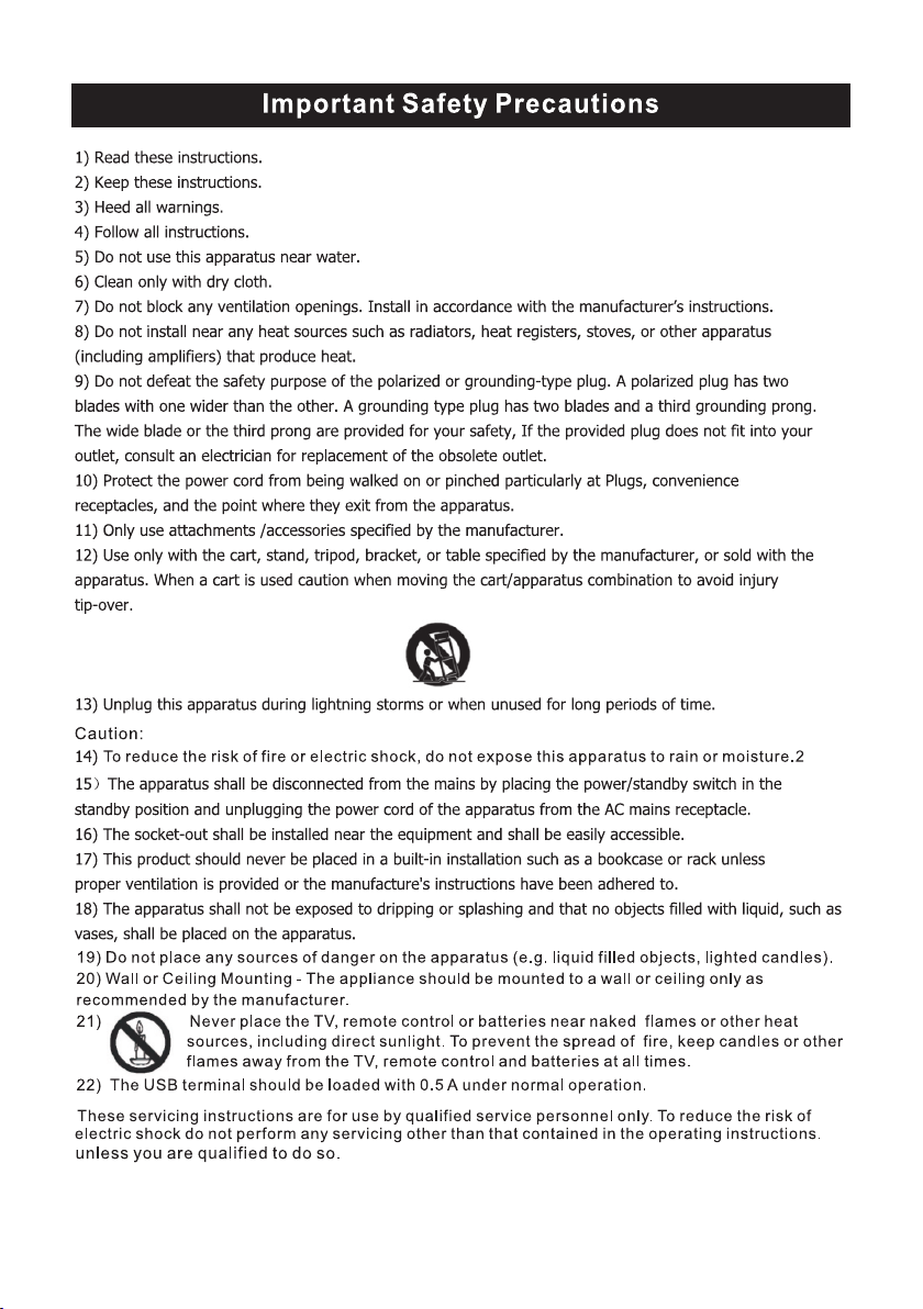
Important Safety Precautions
Wall Mount Installation
TV Bracket assembly
Top/Side panel diagram
Remote Controller
Battery Installation
Using the Remote Control
Install TV
Set your TV
Connect Antenna and power
Turn On TV
Systems Connection
Setup Wizard
Select Input Source
TV
Main Menu Operation
Sound Menu
Time Menu
Setup Menu
Lock Menu
Channel Menu
PC
PC Menu
DVD Setup
Help
Specifications
2
3
4
5
6-7
8
9
10
12-13
14
15-18
15
15-16
16
16-18
19
20
21
22-23
24
25
1
Page 3
Caution
The lightening flash with arrowhead s ymbol, within an equilateral triangle is
intended to alert the user to the presenc e of un-insulated "dangerous voltage"
within the products enclosure that ma y be of sufficient magnitude to constitute a
risk of electric shock to the persons.
The exclamation point within an equil ateral triangle is intend to alert the user to
the presence of important operating a nd maintenance (servicing) instructio ns in
the literature accompanying the app liance.
Correct disp osa l of t his P rod uct
W aste Electrical & Electronic Equ ipment (WEEE)
Your product is designed and manuf actured with high quality materials and
components which can be recycled and re used.
This symbol means that electrical and e lectronic equipment, at their end-of-li fe,
should be disposed of separately from y our household waste.
Please dispose of this equipment at you r local community waste
collection/recycling centre.
In the European Union there are separat e collection systems for used electrical
and electronic products. Please hel p us to conserve the environment we live in!
This Compact disc player is classified as a Class 1 LASER PRODUCT.
2
Page 4
3
Page 5
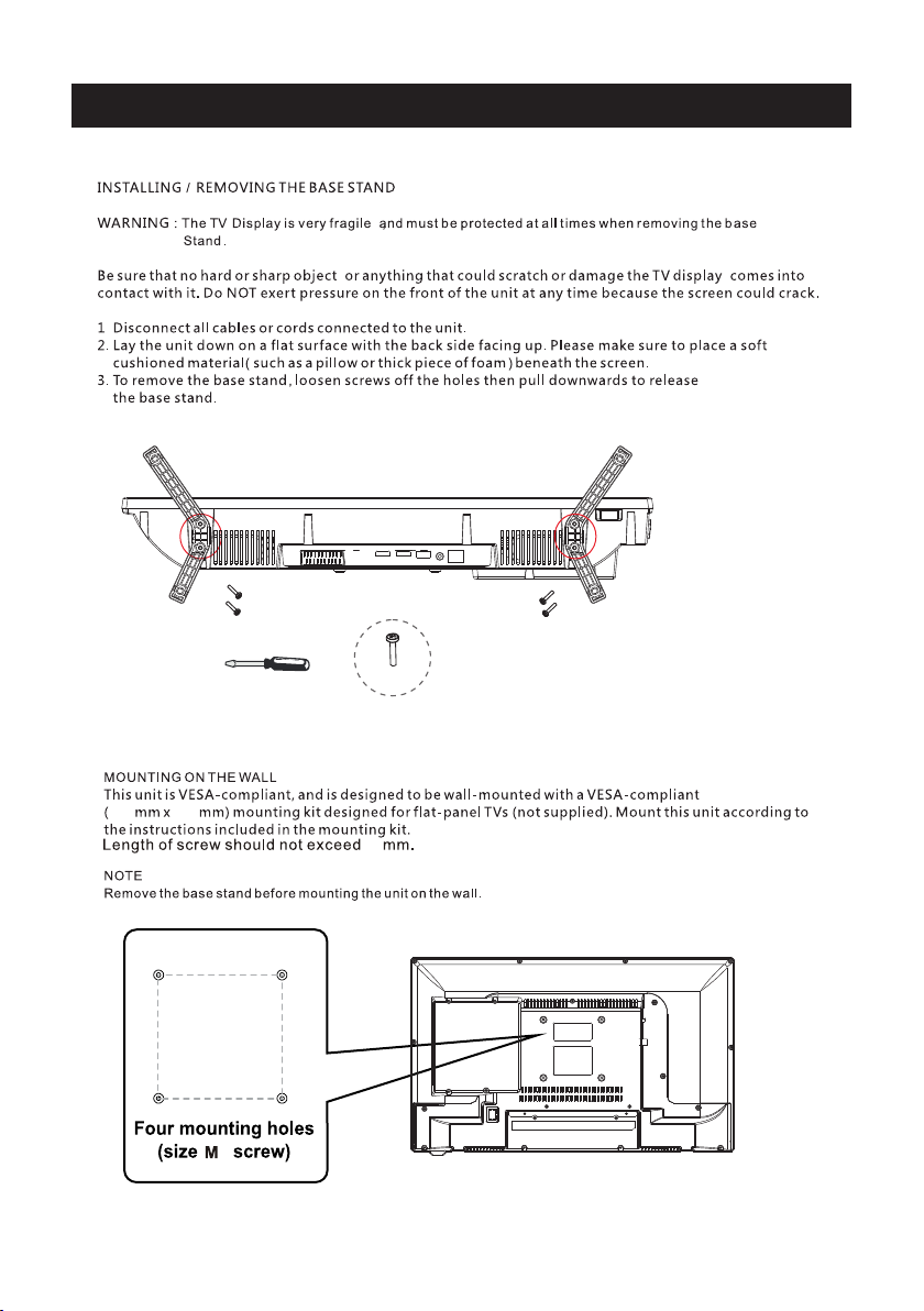
Wall Mount Installation
BB4 * 10mm
100 100
3.9 5” x 3.95 ”
8
3.95”
3.95”
4
4
Page 6
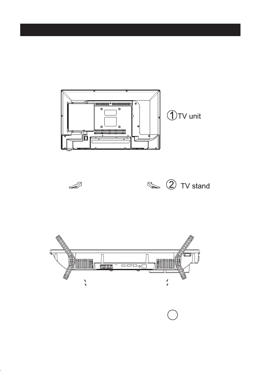
TV Bracket assembly
1.Match the TV unit into the stand, then hold the TV stand,
revolve and lock the tv unit tightly as the arrowhead point.
2.Fix the screws into the TV stand after installing the tv
unit and tv stand.
3
screws
5
Page 7
Top panel diagram
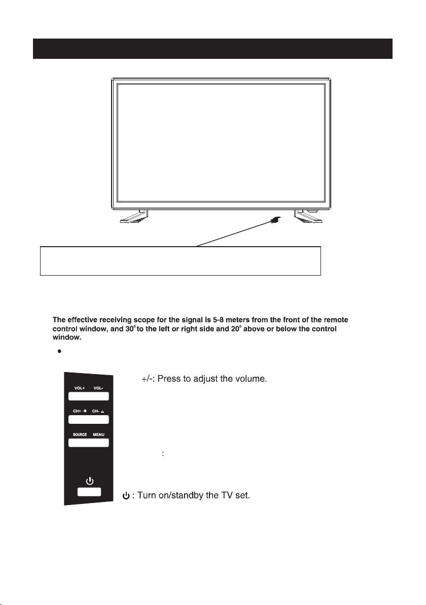
(IR) Infrared Receiver: Receives IR signals from the remote control.
(Power on/Standby) LED Indicator: Press
to turn on and off
Indicator on(Red) Standby mode
Indicator on(Green) Power on mode
The functions of the buttons on the are as follows:TV
VOL
CH+/-:When watching TV: select channels.
/
(DVD Mode. CH-:DVD Eject. CH+:Play/Pause DVD Program)
/
MENU:
1.Press Menu.
2.Use CH+/- to shift UP/DOWN.
3.Press VOL+/-to adjust.
SOURCE External signal input selection
1.Use CH+/- to shift UP/DOWN.
2.Press VOL+ to enter.
6
Page 8
Digi tal
Audi o out
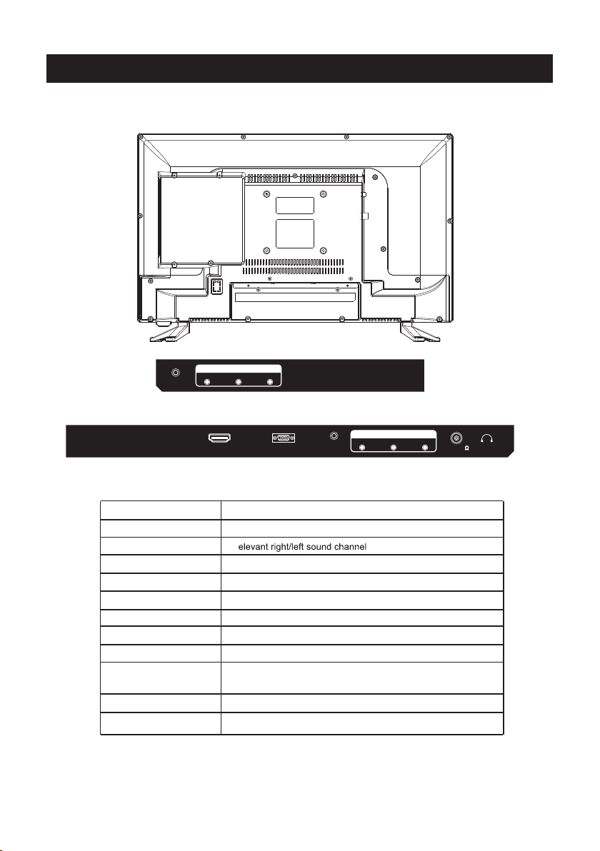
Side Panel Diagram
INP UT
L
VIDE O R
(Left Side)
ser vice po rt
DC IN
Name
Digital Audio Out
L/R INPUT
HDMI IN
VGA IN
PC AUDIO IN
YPbPr
ANT 75 Ω
EARPHONE
Service Port
HDMI
VGA
PC AUDI O
INPU T
INP UT
Y Pb
(Back Side)
Function Description
Digital Audio Output
R
Connect to HDMI of DVD or other equipment
VGA signal from computer output
PC audio input
Connect to the composite terminal of your DVD/VCR
Connect to ANT or cable source
Earphone output
For Upgrade Use
(The service Port is intended for service use only. Please do not connect any device to the port)
7
Pr
ANT 75
EARP HONE
Page 9

Remote Controller
SLEEP: Select amount of time before TV turn
automatically.
S.MODE: Press to cycle through the different sound settings
P.MODE: Press to cycle through the different picture settings
MTS / MP3PROG:
Pres s to sele ct the au dio mod e,you c an sele ct ster eo,Mo no,
or SAP (seco nd audi o progr am)./ When pl aying m p3 disc ,
pres s MP3 PRO G and add t he favo rite mu sic to pl aylis t,
pres s PROG tw o times t o see the p rogra mmed pl aylis t.
EPG:
D.Setup:
CH +/- : P ress to s can thr ough or t o selec t a chann el.
V +/-: P ress to i ncrea se / decr ease th e sound l evel.
off
D.MENU:
D.TITLE:
GOTO:
D.DISP:
STEP:P lay for s ingle f rame im age
Duri ng the pl aybac k,pre ss this b utton t o repea t
A-B
play back of a s pecif ic sect ion on a di sc.
P.MODE S.MODE
MENU
ENTER
EXIT
MTS / MP3PROG
D.setup
FAV FAV+
REV FWD PREV
ZOOM
ANGLE
Angle
Zoom
D.MENU D.TITLE
D.Menu D.Title
PROG STEP
STEP REPEAT A-B
PROG
Pres s "-" to en ter a pro gram nu mber fo r multi ple pro gram
chan nel, su ch as 2-1 e tc.
SLEEP
SOURCE
COM PONEN T DVD
AVTV
PC
DISPLAY
EPG
FAV-
NEXT
AUDIO
SUBTITLE
Audio
Subtitle
ZOOM In DVD source adjust DVD picture size
D.DISP
GOTO
D.Disp
Goto
A-B
REPEAT
HDM I
Univer sal remote cod e
This is the code for remote cont rol of
RTDVD1900 ,if you want to change to a
uni vers al remote cont rol ,you can edit
thi s code into your univers al remot e control.
(1)Open the battery compar tment cover
on the back side
(2)Insert two 1.5V batteri es of AAA type
with correct polarity
(3)Close the battery compa rtment cover
on the back side
Universal Remote Control code:007F
(Universal Remote control is not included)
8
Page 10

10cm
10cm 10cm
LED TV
3
side
indicator
9
Page 11

Digita l
Audio ou t
INPUT
L
VIDEO R
2
Component
PC AUDIO
INPUT
Y Pb
INPUT
Pr
EARPHON E
ANT 75
Digita l
Audio ou t
INPUT
L
VIDEO R
DC IN
servi ce port
HDMI
VGA
10
Page 12

2
DC IN
servi ce port
servi ce port
DC IN
HDMI
PC AUDIO
VGA
INPUT
Y Pb
INPUT
HDMI
Pr
ANT 75
VGA
EARPHON E
PC AUDIO
INPUT
Y Pb
INPU T
Pr
EARPHO NE
ANT 75
11
Page 13

Setup Wizard
Connect an RF cable from the TV’s input called “RF-In” and to your TV Aerial socket.
Select TV Configuration
TV Configuration
Select Time
Press ▼ / ▲ button to select the time zone, daylight saving time and time format you want to.
Press </ > button on the remote control to adjust.
Press ▼ / ▲ button on the remote control to select go to next step and press ENTER/ button
to go.
12
Page 14

Setup Wizard
Auto Scan
Press </ > button to select the antenna type.
Press ▼ / ▲ button to select go to next step and press ENTER/> button to start auto scan.
13
Page 15

Source Select
TV
AV
Component
DVD
HDMI
PC
Main Menu
Select Input Source
Press SOURCE button to display the input source list,
Press ▼ / ▲ or button to select the input
source you want to,
Press ENTER button to enter the input source,
Press EXIT button to quit.
SOURCE
Press MENU to display the main menu or return to the previous menu or close the main menu.
Press </ > to highlight the desired menu icon, and press ENTER to select.
14
Page 16

Main Menu Operation
d)HDMI MODE Video Mode will do overscan, use different aspect ratio;
Graphic Mode do not overscan, display 100 video.C
Adjusting tint will affect the skin tone. -50 will increase red,+50 will increase green.
Ideally, the tint scale on the TV OSD should show the red/green color for easy adjustment.
Picture Menu
ENU to enter th e main menu, Press button to select.Pre ss M
Pre ss to enter.ENTER / ▼
ENU again to exit or back to parent menu.Pre ss M
/
TV
%
Sound Menu
ENU to enter th e main menu, Press butt on to select.Pre ss M
Pre ss to ente r.ENTER / ▼
ENU again to exit or back to parent menu.Pre ss M
/
15
Page 17

button to select among /S ound Mode / Bass / Tre ble / Balance /MTS/ Audio LanguagePre ss ▼ / ▲
/Digital Audio Outp ut/ Surround Sound/ AVL .
Pre ss to ente r. ENTER / ▼
Pre ss button to adjust.</ >
ENU again or back to parent menu. Pre ss M
Time Menu
ENU to enter the main menu, Press button to select.Pre ss M </ >
Pre ss to enter.ENTER / ▼
ENU again to exit or back to parent menu.Pre ss M
button to select among Sleep Timer / Time Zone / Daylight Saving Time / Time Format / Auto Pre ss ▼ / ▲
Clock / Clock.
Pre ss to ente r. ENTER / ▼
Pre ss button to adjust.</ >
ENU again or back to parent menu. Pre ss M
Setup Menu
ENU to ente r the main menu, Press button to select.Pre ss M ◄ / ►
Pre ss to enter.ENTER / ▼
ENU again to exit or back to parent menu.Pre ss M
TV
16
Page 18

TV
ReturnNextMove
Press ▼ / ▲ button to select among Menu Language / Transparent / OSD Timeout / Closed Caption /Over Scan/ Input Label /
Other settings / Restore Default / Setup Wizard/Voice Guidance/Video Description.
Press to enter. ENTER / ▼
Press button to adjust.◄ / ►
ENU again or back to parent menu. Press M
17
Page 19

18
Page 20

TV
Lock Menu
ENU to enter the main menu Press button to select.Press M /
Press to enter.ENTER /
▼
ENU again to exit or back to parent menu.Press M
Rating /RRT Setting / Reset RRT
Press to enter.
Press button to adjust./
Enter your 4-digital password. Default password is 0000,and if forget what you set, please call the
service center.
▲
buttontoselectamong Change Password / System Lock / Input Block / US Rating / Canada Press /
▼
ENTER /
ENU again or back to parent menu.Press M
▼
ReturnNextMove
19TV20
Page 21

Channel Menu
ENU to enter the main menu, Press button to select.Pre ss M </ >
Pre ss to enter.ENTER / ▼
ENU again to exit or back to parent menu.Pre ss M
button to select among Air/C able / Auto Scan / Favorite / channe list / Show/Hide / Channel Number / Channel Pre ss ▼ / ▲
Label .
Pre ss to ente r. ENTER / ▼
Pre ss button to adjust.</ >
ENU again or back to parent menu. Pre ss M
Page 22

PC
PC Menu
SOURCE
to select PC source.
Press
M
ENU to enter the main menu, Press button to select Setup menu.
Press
▼
Press to select PC Settings.
▲
/
Press
Press to enter
Press button to adjust.
Press
buttontoselectamong H-Pos / V-Pos / Clock / Phase / Auto.
▼
ENTER /
</ >
▼
M
ENU again or back to parent menu.
</ >
ReturnSelectMove
21
ReturnSelectMove
Page 23

DVD Setup
Press the “D.Setup” button to enter the DVD settings menu,use the “ ” buttons to select
the desired menu page (General / Audio / Video / Preferences),and use “ ” buttons
to select the items in each menu,then use “ ” buttonto enter the selected item. If you then
change any setting,press “ENTER” button toconfirm the value you changed.Press the “ ”button
to return to the left submenu; to go back up to one of the main DVD menu pages,press
“EXIT” button.
1.General Setup Page
Osd Language:Set the language of the setup menu and screen display.
Screen saver:Set the screen protection.
Last Memory:Remember and resume from the position of the previous playback.
2.Speaker Setup Page
Downmix: This is DVD L/R and stereo output,defaut as stereo output.
22
Page 24

DVD Setup
3.Video Setup Page
Sharpness:adjust the sharpness of the image.
Brightness:adjust the brightness of the image.
contrast:adjust the contrast of the image.
4.Preference Page (Note:This menu page will pop up before put the disc
into DVD.)
TV Type: Select the local TV system (PAL TV/Multi/NTSC TV)
Audio: Disc audio language selection (disc dependent)
Subtitle: Disc subtitle language selection (disc dependent)
Disc Menu: Disc Menu language selection (disc dependent)
Parental: Set the maximum disc rating (Kid Safe/G/Pg/Pg 13/Pgr/R/Nc 17/Adult) that can be
viewed without a password
(default password is 0000)
Password: Change the password
Default: Choose this to restore the original default Preference settings
23
Page 25

Help
24
Page 26

VGA
Resolution
Vert ical fr equen cy hz
640 x480 80 0X60 0 1024x768
HDMI
Format
Vert ical fr equen cy hz
480 i /P
60H Z
Parameter specification
Specifications
60H Z60H Z60H Z
576 i /P
50H Z 50HZ/60HZ
136 0x768
60H Z
720 P
108 0 i
50H Z/60H Z
Screen Size
19”
NTSC / ATSC
PAL, NTSC
800
IN: TV, CVBS, YPbPr, PC AUDIO,VGA, HDMI.
Digital Audio Out
OUT: ,E ARPHO NE.
5W+5W
DC 12V 3A
36W
NOTE:
This user s manual is for reference only .Specications are subject to change
without notice
This product is manufactured and sold by Curtis International Ltd.
RCA, the RCA logo, the two dogs (Nipper and Chipper) logo, are registered trademarks or trademarks
of RCA Trademark Management and are used under license by Curtis International Ltd.
Any other product, service, company, trade or product name and logo referenced herein are neither
endorsed nor sponsored byRCA Trademark Management or its affiliates.
25
 Loading...