

Page 1
Installation and Setup Guide
for the VARIO PSU
Designed to power all VARIO illuminators (including VARIO IP)
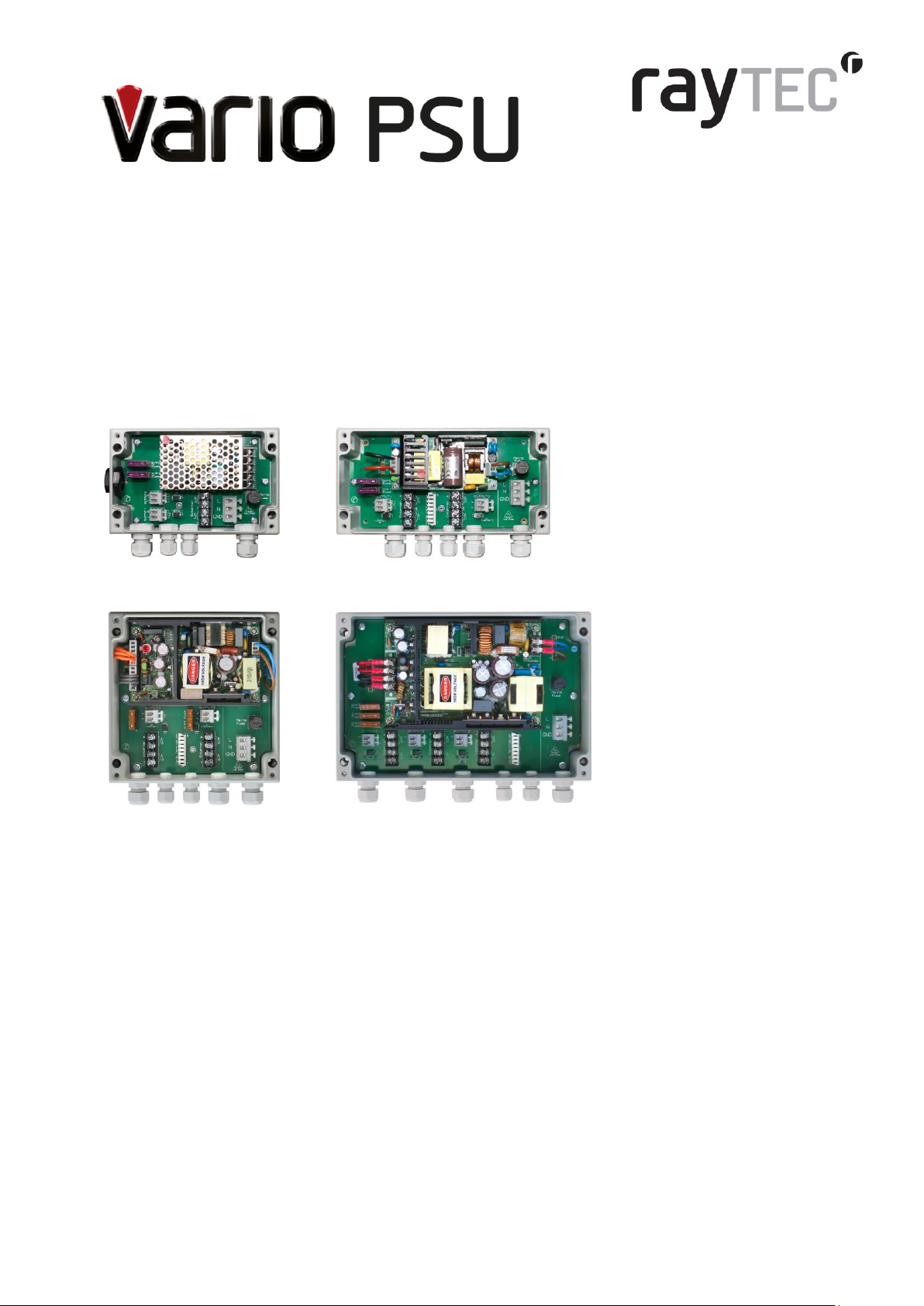
VAR-PSU-1x2 (small) VAR-PSU-2x4 (medium)
VAR-PSU-2x8 (large) VAR-PSU-3x8 (x-large)
Contents
Installation
Setup
VARIO Standard Bracketry
VARIO PSU Specifications
Troubleshooting
Page 2
Installation
Warnings
1 Select interchangeable lens
and mount VARIO illuminator
VARIO is factory set and delivered with a
35˚ beam width. To alter to 10˚, simply
remove interchangeable holographic
diffuser (IHD). To alter to 60˚, replace with
other IHD supplied.
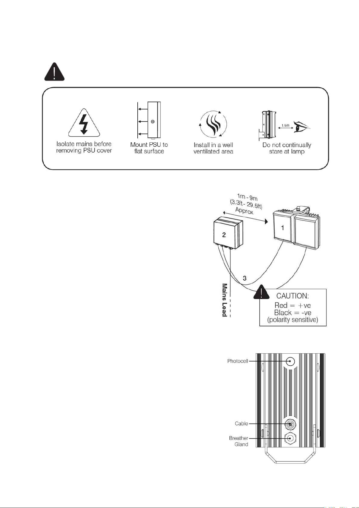
2 Mount PSU
Mount PSU on wall/flat surface with
glands facing down
3 Connect illuminator to PSU
VARIO PSU provides 24V DC
Wiring – six core cable
Red wire +
Black wire -
Installers can extend or reduce lead length using
appropriate cable and weather proof box
Page 3
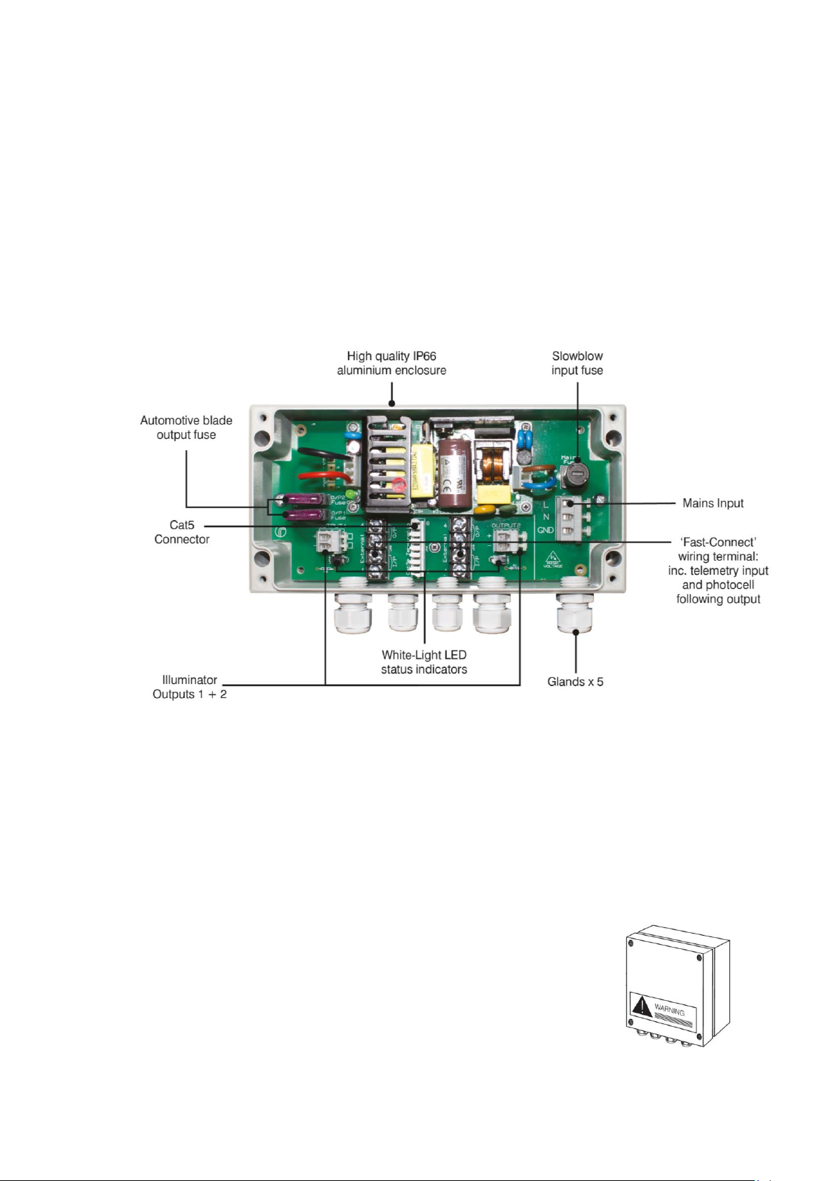
4 PSU Connections
Connect photocell following output/telemetry if required into ‘Fast Connect’ wiring terminal.
Photocell following contact - White & Yellow wires
Volt free output. Non polarity sensitive.
Terminal 1 – white wire
Terminal 2 – Yellow wire
Telemetry input - Orange & Purple wires
Volt free/dry contact or TTL input
Terminal 3 – Orange wire
Terminal 4 – Purple wire
Image featuring VAR-PSU-2x4 (medium)
5 Connect PSU to mains
CAUTION: Ensure cable glands and PSU lid are water tight by tightening the fixings
Golden Rules
Ensure PSU lid orientation has warning label in line with glands
(see PSU diagram, right)
Ensure PSU is fully water tight
Page 4

Setup
1 Position illuminator
Position illuminator adjacent to camera
and point towards scene (Optional night
set-up for optimum image performance)
2 Adjust vertical angle
3 Adjust horizontal angle
Adjust horizontal angle via Adaptive Illumination
(AI) if required (VARIO AI illuminators only)
CAUTION: Do not fully loosen AI bolt
4 Tighten all fixings
5 Final illuminator configuration
Complete configuration and final setup using
VARIO Remote Controller or VARIO IP
Integrated Web Interface (or via 3rd party VMS if
applicable)
Page 5

VARIO Standard Bracketry
Other bracket options available – see specific illuminator instructions.
See VARIO AI Installation instructions for VARIO AI bracketry options.
Page 6

VARIO PSU Specifications
VAR-PSU-1x2
(small)
VAR-PSU-2x4
(medium)
VAR-PSU-2x8
(large)
VAR-PSU-3x8
(x-large)
Illuminators
1 x VARIO 2 series
Plus aux output
(max 8w)
2 x VARIO 4 series
2 x VARIO 8 series
3 x VARIO 8 series
Other Illuminator
options
4 x VARIO 2 series *
4 x VARIO 4 series *
8 x VARIO 2 series *
3 x VARIO 4 series*
*Please note: for medium and large PSUs powering an increased number of VARIO
illuminators, the total power of the illuminators must be equivalent to the PSU max output -
illuminator output cables may also need to be commoned together to suit the number of
available glands.
Mixed model sizes of VARIO illuminators can be powered from the same PSU
e.g. VAR-PSU-2x4 can also run 2 x VARIO 2 series and 1 x VARIO 4 series
Input
100-230V AC
Input Fuse Type
20mm, slowblow, user replaceable without disconnecting mains input
Input Fuse Rating
1A
2.5A
2.5A
2.5A
Max Output
20W
50W or equivalent
power units
100W or equivalent
power units
150W or equivalent
power units
Output for VARIO
Illuminators
1 for VARIO 2 series
2 for VARIO 4 series
2 for VARIO 8 series
3 for VARIO 8 series
Output Voltage
24V DC
Output Fuse Type
automotive, blade, user replaceable
Output Fuse Rating
3A
3A
5A
5A
FastConnect™ wiring
Quick and easy wiring for VARIO input and output connections - 4 way robust terminal for
telemetry input and photocell following output
White Light status LEDs
White-Light LED status indicators on all fused outputs to indicate correct voltage and to
provide support illumination during wiring
Cat5 Connector
N/A
Cat5 Connector for
VARIO IP
Cat5 Connector for
VARIO IP
Cat5 Connector for
VARIO IP
Glands
2x M16, 2x M12,
IP68
3x M16, 2x M12,
IP68
3x M16, 2x M12,
IP68
4x M16, 2x M12,
IP68
Enclosure construction
High quality, power coated, IP66 aluminium
PSU Dimensions
160x100x61 mm
200x100x61 mm
160x160x81 mm
240x160x81 mm
Drilling Dimensions
4 x M4 holes
145 x 63 mm
4 x M4 holes
185 x 63mm
4 x M4 holes
145 x 123mm
4 x M4 holes
225 x 123mm
Weight
0.9kg
1.0kg
1.7kg
2.4kg
IP Rating
IP66
Certification
CE compliant
Accessories available External mounting feet (contact Raytec)
Page 7

Troubleshooting
Ensure all tests are undertaken by a qualified, trained engineer
Ensure safe working practices are followed at all times
Step 1 Basics
Check polarity of illuminator connection: red= +ve, black= -ve
Ensure PSU outputs provide 24V DC
Ensure telemetry wires are shorted out or closed contact input (zero volt) is applied
Check photocell is working. Cover illuminator photocell fully, light should turn on. It is
sometimes difficult to see Infra-Red lamps working in high brightness conditions.
Check mains input
Check fuses intact
If longer cables used, ensure sufficient voltage is provided to allow for drops across the
cable
If OK…
Step 2 Lamp Test
Check current is being drawn – amount of current will depend on power setting of
unit. Please note – use appropriate DC multimeter
To test this you must ensure photocell fully covered (or disabled using optional VARIO
remote controller or VARIO IP web interface) and ensure telemetry wires are shorted out
or closed contact input (zero volt) is applied
Step 3 Set-up Camera, lens and illumination
Check camera lens – fully open at night & set correctly
Check model number to Raytec performance specification to ensure required distance is
achievable;
- Check illuminator is set to max power
- Check orientation of illuminator and ensure it is pointing in correct direction
- Check angle of illuminator (Holographic lens) – Too narrow may cause hot spots
and the aperture of the camera lens to close down. Too wide and there may be
insufficient light on scene and light going where it is not needed.
Page 8

Check the LED status indicator on standard VARIO illuminators (not applicable for
VARIO IP) – if a flashing red light is visible in programming mode, please check the
input voltage of the unit. The feedback system will respond differently depending on
what mode the unit is in (see specific VARIO installation guide for further details)
Step 4 Call Raytec for further assistance
Note down:
Model and serial number of PSU/ illuminator
Camera make and model
Lens make and model
If the Raytec lamp or remote control is still not delivering the
required performance, please contact us for further
assistance:
Raytec Global Tel: +44 (0) 1670 520055
Raytec Warranty
Please register you VARIO PSU for its 3 year warranty by visiting
www.rayteccctv.com/products/warranty-card
 Loading...