


Installation and Setup guide VARIO Series
VARIO w8 |
VARIO i8 |
VARIO w4 |
|
|
|
|
VARIO i4 |
|
|
||
|
|
VARIO w2 |
|
||
|
|
|
VARIO i2 |
||
|
|
|
|
||
|
|
|
|
|
|
Contents |
|
|
|
|
|
Page 2 |
Quick Set-Up and Factory Defaults |
|
|
||
Pages 3 - 4 |
Complete Set-Up and Installation |
|
|
||
Page 5 |
VARIO Remote Controller (VRC) |
|
|
|
|
Page 6 |
Feedback System |
|
|
|
|
Page 7 |
Bracketry |
|
|
|
|
Page 8 |
Specifications |
|
|
|
|
Page 9 - 11 |
Troubleshooting |
|
|
|
|
Box Contents: |
VARIO illuminator with 35˚ beam angle IHD |
|
|
||
|
60˚ beam angle IHD |
|
|
|
|
Accessories: |
VARIO Remote Controller for additional programming of the unit |
||||
(optional) |
80˚ beam angle IHD |
|
|
|
|
|
120˚ beam angle IHD |
|
|
|
|

Installation Steps – Quick Guide
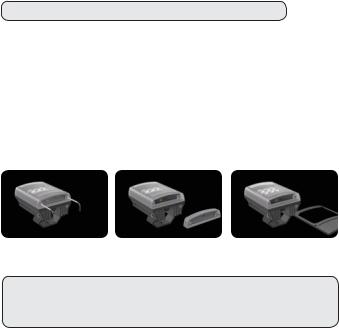
1.VARIO is factory set and delivered with a 35˚ beam width.
To alter to 10˚, simply remove interchangeabIe holographic diffuser (IHD). See page 3 for detailed instructions
To alter to 60˚, replace with other IHD supplied.
2.Mount Illuminator
3.Connect Illuminator to low voltage input 12/24V AC/DC
4.Complete configuration and final set-up using VARIO Remote Controller (VRC) - this is an optional accessory
Wiring - six core cable |
|
|
|
DC |
AC |
Black wire |
- |
~ |
Red wire |
+ |
~ |
White & Yellow wires = Photocell following contact.
Volt free output. Non polarity sensitive.
Orange & Purple wires =
Telemetry input Volt free/dry contact or TTL input
Photocell
Cable
Breather
Gland
•IR Variants
CAUTION - IR emitted from this product – Risk Group 2. Do not stare at the lamp. Avoid exposure or use appropriate shielding / eye protection. Risk Group 2 for cornea / lens infrared hazard.
At a distance of more than 1500mm for all products the unit is in the exempt group.
•White Light Variants
Risk Group 1 classification. Do not stare at the lamp.
2 www.rayteccctv.com |
UK / Europe Tel: +44 (0) 1670 520055 |
|
Americas Tel: +1 613 270 9990 |
Factory Default Set-Up:
35˚ Beam Angle
Max 100% Power Telemetry Input - closed Photocell sensitivity - MID Status LEDs – ON
Programming function will auto-disable after 4 weeks
VARIO Complete Set up and Installation
Step 1. Select different beam angle – if required
VARIO is factory set and delivered with a 35˚ beam width angle.
To alter to 10˚, simply remove interchangeabIe holographic diffuser (IHD) lens. To alter to 60˚, replace with other IHD lens supplied.
Other angle IHD lenses are available to order: 80˚ and 120˚.
All IHD lenses will be clearly marked with the angle which they will produce when inserted into VARIO.
Please handle IHD lenses with care – and do not touch optical film.
Only 1 IHD lens can be inserted into the product at anytime. The product cannot accommodate mutliple IHD lenses at the same time.
We would recommend that power is turned off when replacing IHD lenses.
Remove base plate from VARIO unit using 2.5mm allen/hex key. Insert required IHD lens and re-attach base plate firmly ensuring gasket is correctly located.
IMPORTANT NOTE: Ensure base plate is securely located, the gasket is correctly located and the screws correctly fastened to ensure and maintain IP66 rating of the product.
UK / Europe Tel: +44 (0) 1670 520055 |
www.rayteccctv.com 3 |
Americas Tel: +1 613 270 9990 |
|
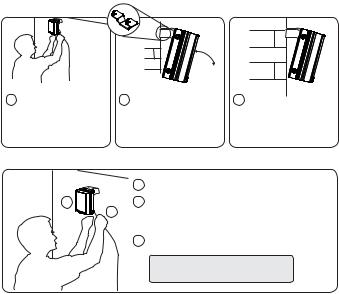
Step 2. Mounting Illuminator
VARIO is delivered as standard with bracket at the bottom of the unit. This can be moved to top the of unit if required. See page 6 for optional brackets
1 Position illuminator adjacent to camera and point towards scene (Optional night set-up for optimum image performance)
TARGET |
|
2 Adjust vertical position of |
3 Tighten all fixings |
lamp to ensure full field of |
|
view illuminated |
|
Step 3 & 4. Connect to low voltage power supply and input 12/24 AC/DC
|
1 |
Mount illuminator |
1 |
2 |
Connect Illuminator to low voltage power supply: |
|
2 |
Installers can extend or reduce lead length using |
|
|
appropriate cable and weather proof box |
|
3 |
Input 12-24V DC/ 24V AC |
Note: Red = positive
Black = negative
Step 5. Telemetry Input (Orange & Purple)
As default will be wired together for standard photocell controlled on/off operation. If required to be activated by PIR or alarm system, connect to appropriate, volt-free input or TTL. Telemetry Input for remote switch or input. Volt free input/dry contact: Non polarity sensitive, short circuit = light on
TTL input: Orange = TTL +ve, Purple = TTL –ve (GND) 0V = Light on, 3V = Light off
Step 6. Photocell following output (White & Yellow)
Volt free output - normally open (day) to normally closed (night). Connect direct to camera if required to control switchover of day/night cameras.
4 www.rayteccctv.com |
UK / Europe Tel: +44 (0) 1670 520055 |
|
Americas Tel: +1 613 270 9990 |
 Loading...