

Page 1
PoE Network Illuminators
Installation should be carried out by suitably trained and qualified
personnel
These Products are Suitable for Internal and External Applications
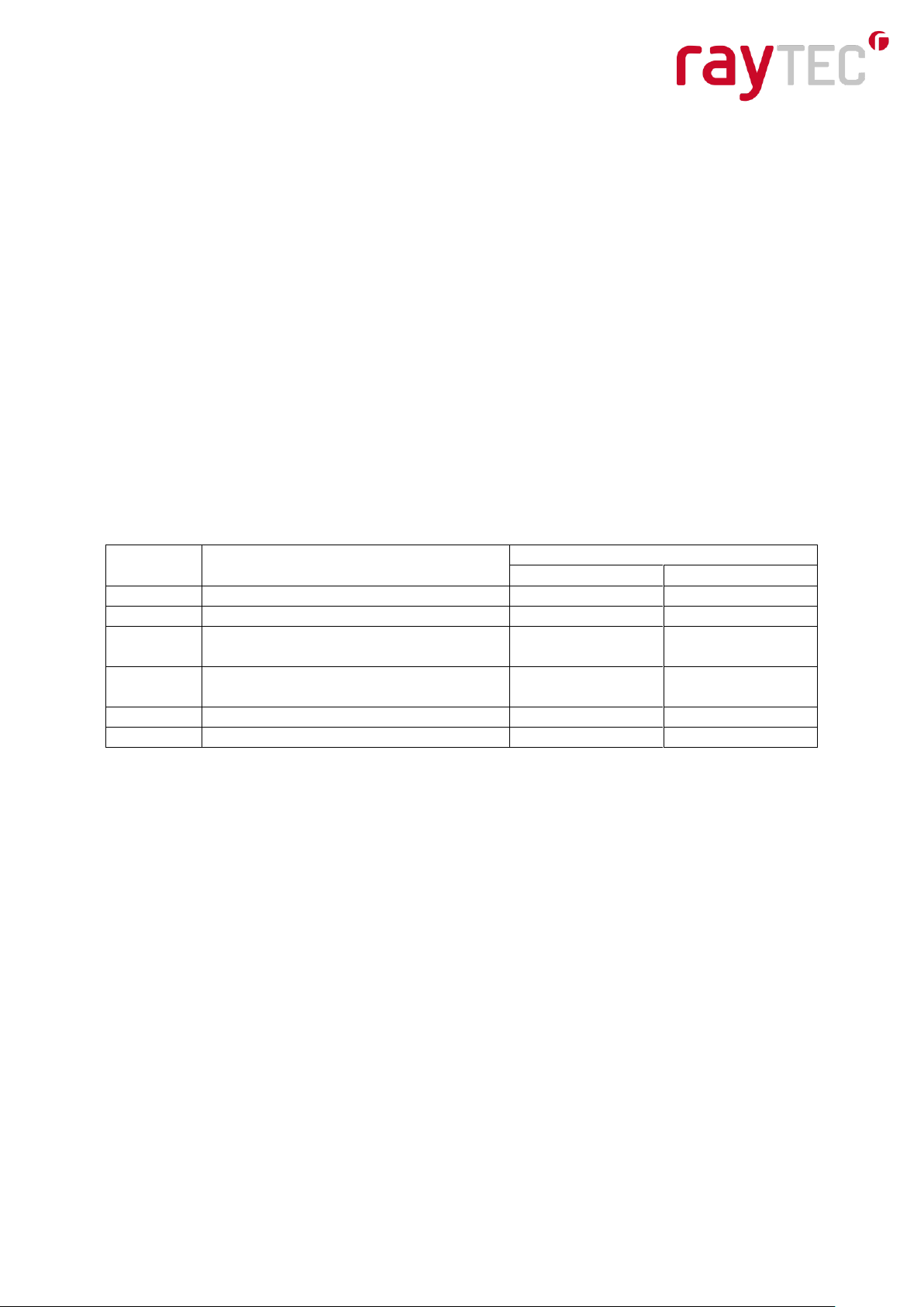
BOX CONTENTS
VARIO IP PoE LAMP Either Infra-Red or White-Light
USB Memory Stick Containing Full User instructions & Raytec Discovery Tool App
Quick Start Instructions
Minimum System requirements: - PC running Windows 7 with IE8 and network access.
WARNINGS
Install in a well ventilated area
IR Variants
CAUTION - IR emitted from this product – Risk Group 2. Avoid prolonged exposure
or use appropriate shielding or eye protection. Risk Group 2 for cornea/lens infrared
hazard. At a distance of more than 1500mm for all IR850 (VAR-IPPOE-i4-1, i8-1)
products or 1300mm for all IR940 (VAR-IPPOE-i4-1-c, i8-1-c) products the unit is in
the exempt group.
White Light Variants
Risk Group 1 classification. Precautions are only required for prolonged eye
exposure. Do not stare at the lamp.
www.rayteccctv.com 1
Raytec Global Tel: +44 (0) 1670 520055
Raytec Americas Tel: +1 613 270 9990
Page 2
VARIO IP PoE Unit
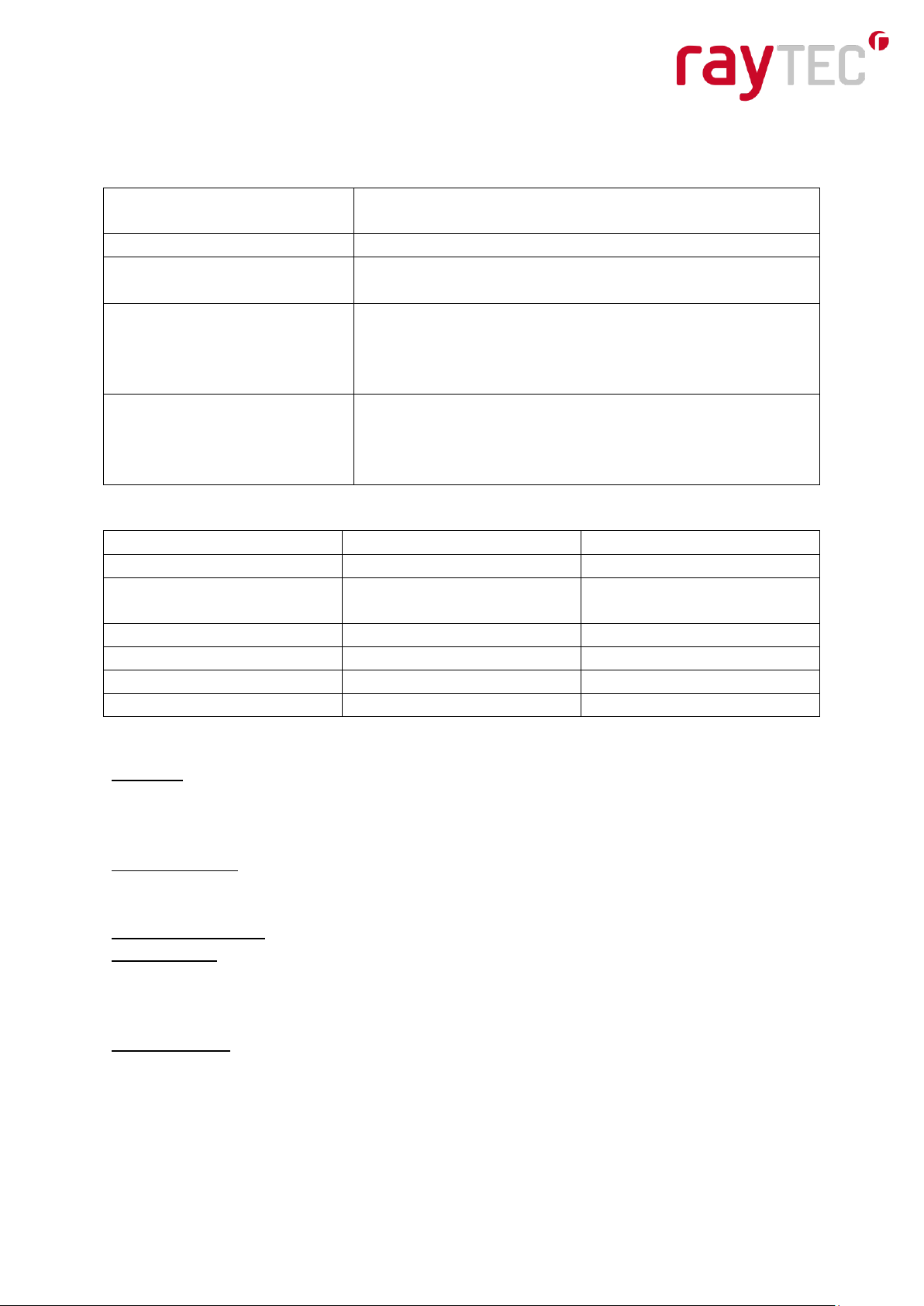
PoE Requirement
VAR-IPPOE-w4-1, i4-1, i4-1-c
IEEE 802.3at (HP PoE) 25.5W
VAR-IPPOE-w8-1, i8-1, i8-1-c
4-pair POE >50W
Colour
Description
Wire Gauge (AWG)
w8-1, i8-1, i8-1-c
w4-1, i4-1, i4-1-c
Red
+ve Auxiliary Power
18
22
Black
-ve Auxiliary Power
18
22
Orange
External Input (Only if TTL:
+ve)
22
22
Purple
External Input (Only if TTL:
GND)
22
22
Yellow
External Output
22
22
White
External Output
22
22
Wiring
The lamp is supplied with a waterproof Ethernet connection (RJ45) on a flying lead and a
Multi-core auxiliary power and control cable.
If using PoE, connect an Ethernet cable (category 5 or better) between the Power Sourcing
Equipment (PSE) and the lamp. Ensure that the PSE is sufficiently rated to power the Vario
IP POE device. Requirements are as follows:
When using PoE the CAT5 cable is both the power and data connection for the lamp. The
maximum Ethernet cable length is 100m (328’) without boosting the signal.
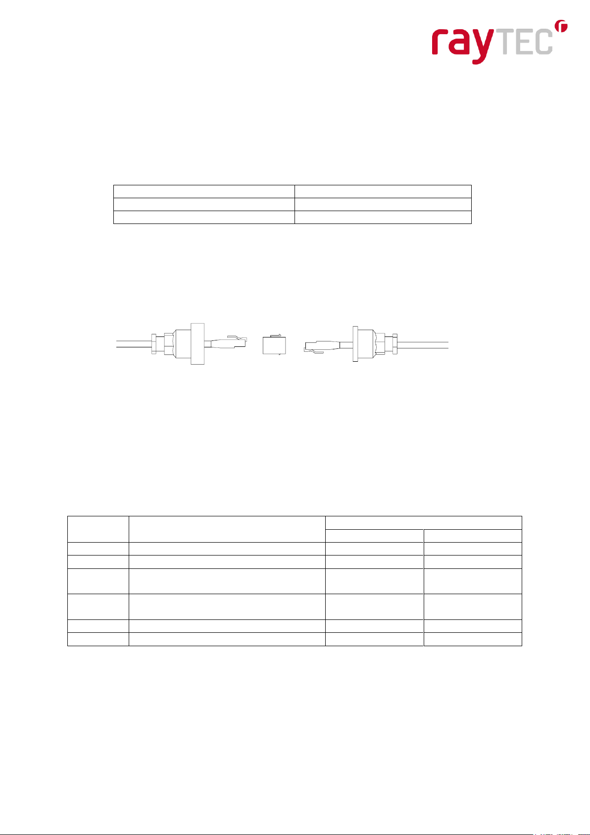
Ensure you make a waterproof connection to the RJ45 as shown below. Ensure the
connector is waterproof and sealed after the connection is made.
To lamp RJ45-RJ45 connector To Network
If using Auxiliary Power, connect 24V DC to the red (+ve) and black (-ve) cables of the
multicore auxiliary cable. In this case the Ethernet cable is a data connection only and
supplies data signals to/from the lamp.
Connect external input trigger and external output as required – see table below
Please Note : To maintain the environmental integrity of the product, as part of the
installation, the multicore auxiliary cable must be terminated appropriately regardless of
which cores are being used.
www.rayteccctv.com 2
Raytec Global Tel: +44 (0) 1670 520055
Raytec Americas Tel: +1 613 270 9990
Page 3
Detection Resistance Selection Switch
Changing Interchangeable Lenses
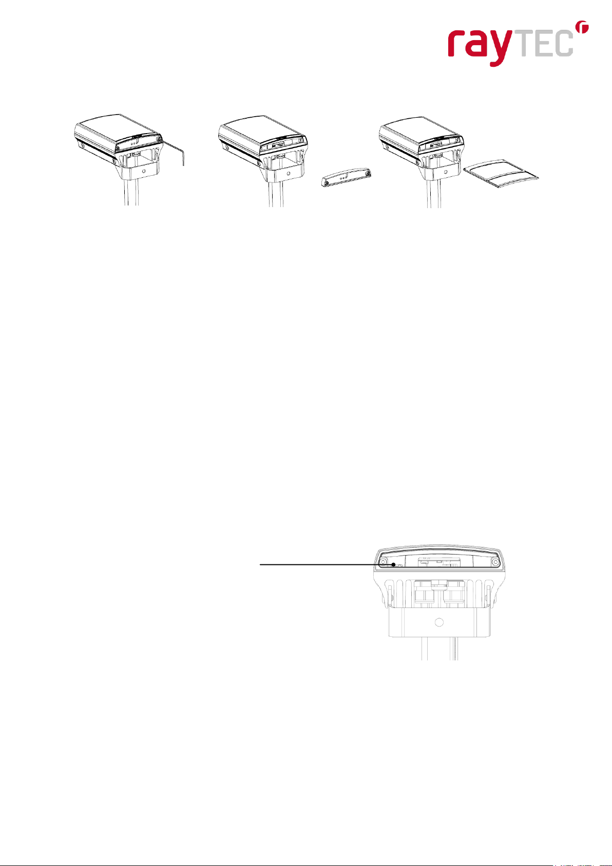
To alter the angle of your lamp – see the drawings above.
The lamp is delivered with a 35o angle. To alter to 10o, remove the baseplate from the
bottom of the product and remove the existing lens and then re-attach the baseplate.
To alter to any other angle, remove the existing lens and insert the required lens (which will
have its angle indicated). Ensure the baseplate is securely re-attached to maintain
waterproof integrity of the product.
POE Detection Resistance Selection Switch
There is a switch on the VAR-IPPOE-w8-1, i8-1 and i8-1-c lamps which can be used to
change the POE detection resistance of the lamp.
Turn the power to the lamp OFF, remove the baseplate and access the switch as shown.
The majority of PSE equipment requires a detection resistance of 24.9KΩ to establish a
POE link. Some Phihong brand PSE equipment requires a 12.5KΩ detection resistance.
For 24.9 KΩ, slide switch to the LEFT (as shown). For 12.5 KΩ, slide switch to the RIGHT.
www.rayteccctv.com 3
Raytec Global Tel: +44 (0) 1670 520055
Raytec Americas Tel: +1 613 270 9990
Page 4
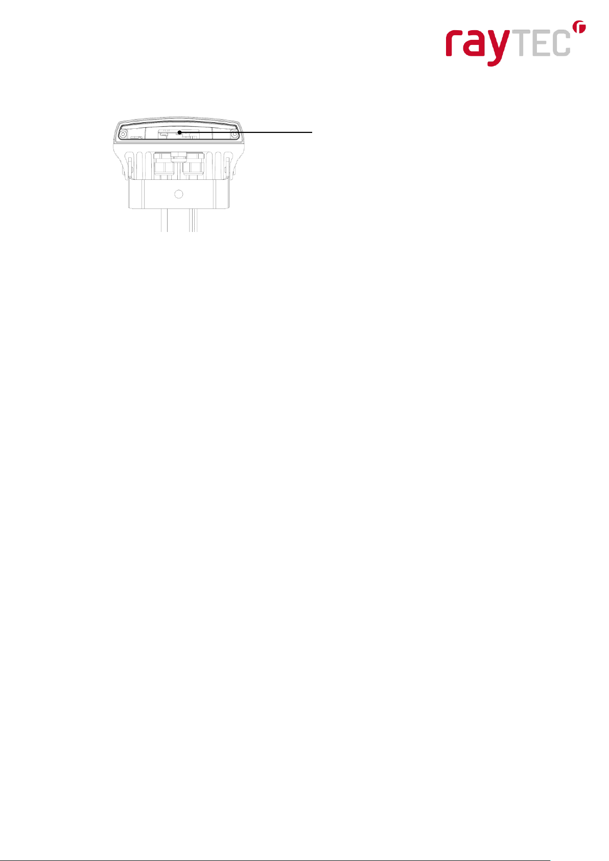
Hard Reset Button
Hard Reset – On the Lamp
There is a hard reset button on the lamp which can be used to reset the lamp in case all
connectivity is lost.
Turn the power to the lamp OFF, remove the baseplate and access the button as shown.
Press and hold the Reset button and reconnect power. Keep the Reset button pressed for
about 5 seconds until the lamp flashes. Release the Reset button. Ensure the baseplate is
securely re-attached to maintain waterproof integrity of the product.
All settings will be lost and the factory default settings will be restored.
WARNING: We recommend attempting to reconnect with the lamp by firstly restarting the
lamp or restoring factory settings via the integrated web interface. The hard reset button on
the lamp should be used only as a last resort to restore connection to the lamp.
www.rayteccctv.com 4
Raytec Global Tel: +44 (0) 1670 520055
Raytec Americas Tel: +1 613 270 9990
Page 5

Table of Contents
..................................................................................................................................... Pages
Quick Set Up – wiring, changing lenses, hard reset ........................................................... 2-4
Introduction ........................................................................................................................... 6
Quick Start ......................................................................................................................... 6-7
Hierarchy of Photocell & Telemetry ....................................................................................... 8
Quick Troubleshoot .............................................................................................................. 8
Factory Defaults .................................................................................................................... 9
Connecting to the Network…………………………………………………………………………10
Discovery Application Tool ............................................................................................. 10-14
Web Pages ....................................................................................................... 15-30
Home Page/Instant Control ............................................................................. 16
Settings /Groups ........................................................................................ 18-23
Access ............................................................................................................ 24
Network ........................................................................................................... 25
System Information ......................................................................................... 26
Diagnostics ...................................................................................................... 28
Advanced Diagnostics ..................................................................................... 29
Software Update ............................................................................................... 29
Log Off ............................................................................................................. 30
Hard Reset button on lamp ................................................................................................. 31
Troubleshooting .................................................................................................................. 32
API ...................................................................................................................................... 32
www.rayteccctv.com 5
Raytec Global Tel: +44 (0) 1670 520055
Raytec Americas Tel: +1 613 270 9990
Page 6
Colour
Description
Wire Gauge (AWG)
w8-1, i8-1, i8-1-c
w4-1, i4-1, i4-1-c
Red
+ve Auxiliary Power
18
22
Black
-ve Auxiliary Power
18
22
Orange
External Input (Only if TTL:
+ve)
22
22
Purple
External Input (Only if TTL:
GND)
22
22
Yellow
External Output
22
22
White
External Output
22
22
Introduction
VARIO IP PoE is a Network Illuminator designed to connect to any suitable network and is
provided with an integrated Web Interface. The product is delivered with a Discovery Tool
Application for easy identification and connection to the lamp on the network. You can also
connect directly to the lamp by typing its IP address into a web browser. An API is also
available for easy integration within a VMS environment.
The lamp has Operator and Administrator log-on and access rights. The Operator has
access to the Homepage/Instant Control and Diagnostic pages. The Administrator has
access to all pages.
Initial Setup
Ethernet Cable
Cat5e (or better) – using the T-568B wiring standard. See connection on page 2
Multi-core Power & Signal Cable
QUICK START
Select required angle for lamp. Standard angle is 35°. Change angle as required (see page
2).
Attach lamp to wall, housing or pole using U-bracket provided or dedicated Raytec bracketry.
Connect lamp to PSE and network using waterproof connector provided or separate junction
box. See page 2 for diagrams.
To use Auxiliary Power, connect lamp to 24V DC (50W required for VAR-IPPOE-w8-1, i8-1
and i8-1-c, 25.5W required for VAR-IPPOE-w4-1, i4-1 and i4-1-c) and apply power to the
lamp.
We strongly recommend that you load the Discovery Application onto your computer - and
then run it - with the VARIO IP powered and attached to the same network as your
computer.Press Discover – and the Discovery Tool will display a list of lamps available on
the network. You can double click onto the lamp from the Discovery Tool to navigate directly
to the lamp. The default IP address of the product: 192.168.2.80 - which is likely to be
outside of your network range.
www.rayteccctv.com 6
Raytec Global Tel: +44 (0) 1670 520055
Raytec Americas Tel: +1 613 270 9990
Page 7

Users & Passwords
name
password
Operator
user
password
Administrator
admin
password
The lamp does NOT have DHCP enabled to auto allocate IP addresses - but you can
activate that from the Discovery Tool. This is likely to be the easiest and fastest way to
allocate a new IP address, provided that your network is DHCP enabled.
The lamp responds to multicast messages - and therefore does not need to have a valid IP
address for the Discovery Tool to find it. But it does require a valid IP address for
communication.
To change the IP address so you can communicate with the lamp you can either:
1. Run Discovery Tool. Single click on lamp to highlight it. Select <Network> from bottom
menu. Highlight DHCP option. Press save. Then return to Discovery Tool. Press Discover.
Lamp should now appear with a valid IP address. You can now double click lamp to navigate
to it. WARNING: Your network must have DHCP capability.
2. Run Discovery Tool. Single click on lamp to highlight it. Select <Network> from bottom
menu. Write in a new IP address and subnet mask - which must be compatible with your
network. Check with your IT manager. After changing the IP address and subnet mask,
press save. Press Discover.You can now double click lamp to navigate to it.
Alternatively, you can navigate directly to the lamp by typing in the IP address of lamp into a
web browser on a computer located on the same network as the lamps. To ensure
successful communications the IP address of the PC must be in the same IP address range
of the lamps.
Log-on using Operator/User or Administrator user names and passwords. Operator has
limited access rights. Administrator has full access rights.
Defaults (User Names & Passwords are case sensitive):
In order to maintain maximum security of your system, you may want to consider changing
the passwords at the earliest opportunity – see page 23.
Take instant control of lamp by pressing Override button on home page. This will countdown
for 30 minutes to allow user to control and then will revert to standard settings automatically
or if the override button is deselected.
If you wish to have lamp operated via its integrated web browser – then ensure that local
control box on Settings/Groups page is ticked. This is the default. To operate the lamp via
VMS or Raytec software, then deselect the local control box.
Standard set up – see factory defaults below for all default settings.
The lamp will turn on/off automatically when the photocell detects it is dark/light@ 100%
(soft start) via the photocell.
The External Input will activate the lamp @ 100% (NOT soft start) for the duration of the
input provided the photocell detects it is dark.
External Output: activated by photocell, short circuit
Different Settings can be selected on Settings/Groups page. Settings must be saved for
them to take effect.
We recommend that you log off after using the lamp.
www.rayteccctv.com 7
Raytec Global Tel: +44 (0) 1670 520055
Raytec Americas Tel: +1 613 270 9990
Page 8

Hierarchy of Photocell Vs Telemetry
If the telemetry function is enabled, then the photocell must detect that is it dark for the
telemetry function to operate. The photocell overrides the telemetry function during the day.
If the external input/telemetry function needs to be operated 24/7, then the photocell function
should be disabled from the settings/groups page.
The system requires 15 seconds of light to deactivate the photocell and turn the lamps off to
avoid accidental turn off of the lamps via car headlights or torches.
Quick Troubleshoot
Ensure correct lens angle selected for required distance – check stated performance.
Ensure lamp in correct orientation.
Ensure camera fully operational and lens fully open at night.
Check POE equipment is correctly rated for the Vario IP POE unit. On VAR-IPPOE-w8-1,
i8-1 and i8-1-c units check the detection resistance switch is in the correct position for your
PSE.
If using Auxiliary power, check voltage applied to VARIO IP PoE: - 24V DC (50W required
for VAR-IPPOE-w8-1, i8-1 and i8-1-c, 25.5W required for VAR-IPPOE-w4-1, i4-1 and
i4-1-c).
Check connection and wiring of Cat 5/6 cable to VARIO IP. Verify link has been established
with the router/switch to which the lamp is connected.
If a physical connection is present run the Discovery Application and try to discover the lamp
on the network.
If the lamp is discovered and the “State” indicator is grey, this indicates that there is no
communications with the lamp – check IP Address and Subnet Mask are set within the
correct range.
www.rayteccctv.com 8
Raytec Global Tel: +44 (0) 1670 520055
Raytec Americas Tel: +1 613 270 9990
Page 9
Name
VARIOIP
Group Name
<Deliberately Left Blank>
IP Address
192.168.2.80
Enable DHCP Checkbox
Not Selected – IP addresses will NOT be automatically
allocated. If lamp is being operated on a DHCP enabled
network, DHCP can be selected for automatic allocation of
IP address.
Local
(No VMS server)
selected to enable operation of lamp using integrated web
interface.
If lamp is to be operated using VMS or other control system
then this option should NOT be selected.
Photocell
External Input
Trigger Control
Lamp Control
Lamp Control
Respond to Group
Commands
No, ignore group command
No, ignore group command
Lamp Mode on Trigger
On
On
Power (%)
100%
100%
Duration
All night
Duration of Input
Soft Start
On
Off
Factory Defaults
Deterrent
Pattern = SOS
Frequency = Slow
Manual Override
Countdown Duration = 30 mins
Advanced Settings
External Input
Type of Input = Volt Free
Active State = Short Circuit/Low
External Output
Trigger State = Photocell Only
Active State = Short Circuit/Low
Photocell Sensitivity = 20 lux
www.rayteccctv.com 9
Raytec Global Tel: +44 (0) 1670 520055
Raytec Americas Tel: +1 613 270 9990
Page 10
Connecting to the Network
Basic
Assign an IP Address
Most networks today have a DHCP server that automatically assigns IP addresses to
connected devices. If your network does not have a DHCP server, the VARIO IP Lamp will
use 192.168.2.80 as the default IP address. Raytec’s Discovery Application is the
recommended method for changing an IP address. This free application is available on the
USB Memory Stick supplied with the product or please contact Raytec to supply the latest
version.
See page 6 for how to change the IP address of lamp using the Discovery Tool.
Note: - If assigning the IP address fails, check that there is no firewall blocking the operation
and that the computer and lamp have IP addresses in the same range.
Advanced
Accessing the lamp from the Internet
Once installed, your Network Lamp is accessible on your local network (LAN). If you wish to
access via the internet, please contact your IT specialist.
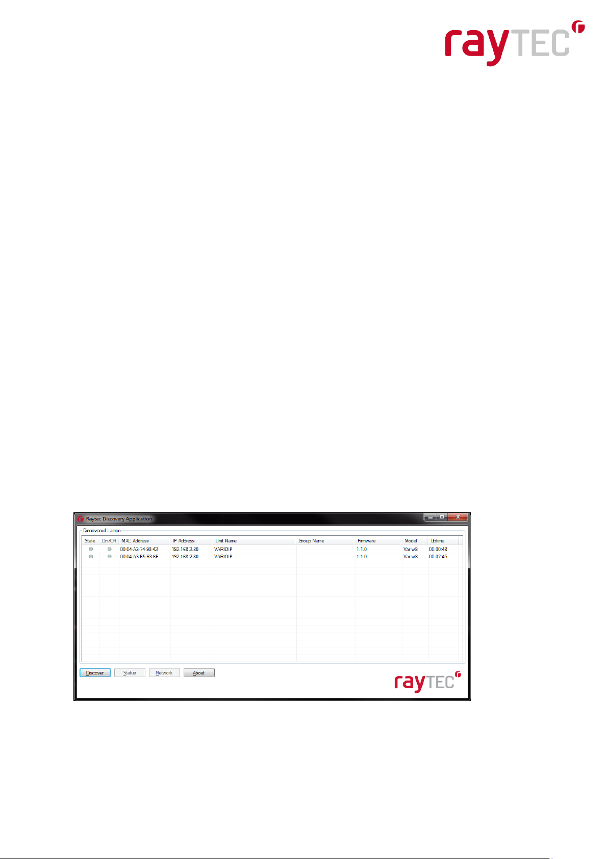
Discovery Application
The Raytec Discovery Application will discover and display all VARIO IP Lamps on your
network. Load The Discovery Tool Application from the USB provided (or contact Raytec for
a copy) onto a computer on the same network as the lamp. Run the application and press
“Discover”.
The Raytec Application allows you to:-
Navigate directly to each lamp
Change Network Settings
www.rayteccctv.com 10
Raytec Global Tel: +44 (0) 1670 520055
Raytec Americas Tel: +1 613 270 9990
Page 11

Change the Name and Group Name
See the lamps status
See lamp details including Names, Firmware version, Time lamp has been powered
etc
To be able to do this communications with the lamp is needed. On the image shown above
two lamps have been discovered on the network. They are unique in that they have different
MAC addresses, but the same IP Address and Unit Name. The application allows the lamps
now to be configured.
Network Settings
To change the network settings highlight the lamp to be changed and press “Network”.
The “Network Configuration” screen will be shown.
Two options are available to set the IP Address at this stage:-
1. Enable DHCP – if the network is DHCP enabled (Recommended)
2. Enter a Static IP Address and Subnet Mask
DHCP – Automatic allocation of IP address
Select “Enable DHCP” and press OK.
The unit will now be allocated an IP Address via the network’s DHCP server. Refresh the
Discovery Application by pressing “Discover”. The lamp’s IP address should automically be
updated into the required range and can be accessed directly from the Discovery Tool now
by double clicking on the lamp from the list of discovered lamps.
www.rayteccctv.com 11
Raytec Global Tel: +44 (0) 1670 520055
Raytec Americas Tel: +1 613 270 9990
Page 12

Static Network Configuration – Manual allocation of IP address
To use static network configuration it is important that the network administrator controls and
ensures the IP Addresses issued are unique and not repeated. Enter the appropriate IP
Address and Subnet Mask in the “Use the following IP address” section and press “OK”.
The unit will now be allocated the IP Address as entered. Refresh the Discovery Application
by pressing “Discover”.
Name and Group Name
All lamps have the default name of “VARIOIP”. This should be changed so that the lamp can
be easily identified.
The group name is always left blank as default. The group name is used to associate/group
lamps together and allow them to interact using group commands.
Both Name and Group Name can be modified directly from the Discovery Application or via
the web interface.
To change these via the Discovery Application, highlight the lamp you want to change. Then
press “Status”.
Unit Name and Group Name can both be edited by entering a new value in their fields.
www.rayteccctv.com 12
Raytec Global Tel: +44 (0) 1670 520055
Raytec Americas Tel: +1 613 270 9990
Page 13

Red
Green
Grey
State
Lamp Fault
Lamp OK
No communication
On/Off
N/A
Lamp On
Lamp Off
After the change has been made save the edited names by pressing “OK”.
The selected unit name and group has now been changed. Refresh the Discovery
Application by pressing “Discover” and the updated information should be displayed.
Lamp Status
The Discovery Application has two status indicators for each lamp. The colours of these
indicators change depending on the state of the lamps as described below:-
A lamp fault is indicated if:-
1. An LED fault exists within the lamp.
2. The input voltage is outside specified limits.
Other Information
The Discovery Application does not automatically refresh, therefore to view any changes it is
important that the page is refreshed - using function key “F5” or by pressing “Discover”.
When changes are made to a lamp or a new lamp is added there may be a small delay in
making contact or updating the information and so “Discover” may need to be pressed more
than once.
www.rayteccctv.com 13
Raytec Global Tel: +44 (0) 1670 520055
Raytec Americas Tel: +1 613 270 9990
Page 14

Unit Details – Parameters
Selecting the Parameters button within the Unit Details screen provides a high level of
detailed information regarding the performance and operation of the lamp. This is designed
to be used during detailed diagnostics of the lamp with Raytec or your supplier.
www.rayteccctv.com 14
Raytec Global Tel: +44 (0) 1670 520055
Raytec Americas Tel: +1 613 270 9990
Page 15

Users & Passwords
name
password
Operator
user
password
Administrator
admin
password
Web Pages
LOG-IN PAGE
Access Log-In page for individual lamp by double-clicking on the lamp from the Discovery
Tool or by typing the IP address into the web browser.
User Names & Passwords are case sensitive.
Log on using either Operator User Name and Password or Administrator User Name and
Password.
Operator has restricted access to Home Page/Instant Control and Diagnostic Pages only.
Administrator has access to all pages.
The Administrator can change passwords by using the “Access” Page.
Ensure you keep a note of passwords used in a secure place.
Forgotten password
If you are an operator, please request the assistance of the administrator. They can reset the
password through the “Access” Web page.
If you are an administrator, you will have to use the Hard Reset button on the lamp – refer to
instructions on page 30. This will restore the lamp to factory defaults which includes user
names and passwords.
www.rayteccctv.com 15
Raytec Global Tel: +44 (0) 1670 520055
Raytec Americas Tel: +1 613 270 9990
Page 16

HOME PAGE
After a successful log-in, the Home Page/Instant Control page will be displayed.
You can navigate to all pages using the side navigator bar which is available on all pages.
The Home Page/Instant Control page displays the current status of the lamps including the
following information:
- A visual representation of the product and its current state (ON/OFF)
- Product Type & Model
- Product Name - if a name has been assigned (using Network Page or Discovery
Tool)
- Group Name - if a name has been assigned (using Settings/Group Page or
Discovery Tool)
- Trig – if lamp is on, this will indicate the nature of the input trigger type
HOME PAGE/INSTANT CONTROL
All users can access Instant Control features shown below by selecting the “Overide” button.
When selected, additional features will appear and Override countdown will commence.
Factory default Override countdown is 30 minutes. This setting can be adjusted by
administrator on Settings/Group page. The countdown duration can be reset at any time and
will restart from maximum time. The Instant Control Override function can be deselected at
any time and the lamp will return to normal operating mode.
ON & GROUP ON
The current on/off status will be displayed by the red/green button together with the current
power level of the individual lamp. To alter power, use the slider bar from 20% to 100%.
To turn all lamps on in the same group and control power level – select the Group ON
button.
All lamps in a group will turn on to the power setting selected.
www.rayteccctv.com 16
Raytec Global Tel: +44 (0) 1670 520055
Raytec Americas Tel: +1 613 270 9990
Page 17

When ON or GROUP ON button is turned off, lamps will return to their normal operating
mode.
Important - If a lamp is in group override control from another lamp you will not be able to
access the override control on that lamp.
BOOST & GROUP BOOOST
This will boost individual lamp or all lamps in a group (if GROUP BOOST selected) to 120%
of normal output power for a period of 10 seconds. Boost will then be disabled for 100
seconds whilst system recharges.
DETERRENT & GROUP DETERRENT
This will turn individual lamp or all lamps in group (if GROUP DETERRENT selected) into
deterrent mode. The current pattern and frequency of the deterrent is displayed and can be
changed on SETTINGS/GROUP Page. Power setting of lamp(s) in deterrent mode can also
be adjusted by using slider bar.
www.rayteccctv.com 17
Raytec Global Tel: +44 (0) 1670 520055
Raytec Americas Tel: +1 613 270 9990
Page 18

SETTINGS/GROUPS
This page is used to configure the operation of the lamp based on Photocell and/or External
Inputs.
The lamp can be configured to operate from the above inputs independently and the power
level, duration and soft start function can be configured.
www.rayteccctv.com 18
Raytec Global Tel: +44 (0) 1670 520055
Raytec Americas Tel: +1 613 270 9990
Page 19

WARNING: For changes to take effect, the SAVE button must be pressed
WARNING: You cannot see the effect of your changes if the override button on the
Home Page is still active (green) or your lamp is in group override control from
another lamp
Local (No VMS server)
For the lamp to operate from the integrated web interface – this tick box must be selected. If
the lamp is to be operated from a VSM or other control system, then this tick box must NOT
be selected.
Group Name
A lamp can be associated with a new or existing group to enable it to follow group
commands from the photocell input and/or External Input. A new group name can be created
by typing into the <Enter Group Name> box. Ensure that duplicate names are avoided. Or
the lamp can be allocated to an existing group by selecting an existing group from the drop
down list of groups.
Trigger Control
For both Photocell and External Input, the user can select 3 action states:
1. Inactive the lamp ignores the input
2. Lamp Control the lamp will respond to its own input
3. Group Control the lamp will respond to an input from lamps within its named
Group – based on selection from Respond to Group Commands
below
Factory Defaults: Photocell Lamp Control
External Input Lamp Control
Respond to Group Commands
If Group control is NOT selected from Trigger Control options, then the lamp will not respond
to any Group commands.
If Group Control is selected from Trigger Control options, then the user can select two
modes of operation in response to Group Commands:
www.rayteccctv.com 19
Raytec Global Tel: +44 (0) 1670 520055
Raytec Americas Tel: +1 613 270 9990
Page 20

1. Yes, Send & Receive
The lamp will both originate group
commands based on the trigger AND
respond to group commands from other
lamps in its group
2. Yes, Receive only
The lamp will only respond to group
commands from other lamps in its group but
it will NOT originate any group commands
Factory Defaults: Photocell No, ignore group commands
External Input No, ignore group commands
Lamp Mode on Trigger
This will dictates the status of the lamp on receipt of a valid instruction from Photocell and/or
External Input. For both the Photocell and the External Input, the lamp can either be
programmed to stay off or to turn on.
In addition, the External Input can activate the Deter mode – which can be configured below.
Factory Defaults: Photocell On
External Input On
Power
This will dictate the power the lamp turns on at in response to a valid instruction. Power
levels can be set from 20% min to 100% max by using the slider bar.
Factory Defaults: Photocell 100%
External Input 100%
Duration
This will dictate the amount of time the lamp turns on (if on command is selected) from
receipt of a valid instruction.
www.rayteccctv.com 20
Raytec Global Tel: +44 (0) 1670 520055
Raytec Americas Tel: +1 613 270 9990
Page 21

For the Photocell input, user can select “All Night” in which case the lamp will stay on (if on
command is selected) for the whole period of time that the photocell indicates it is dark.
Alternatively, a specific time period can be selected using the slider bar.
The timer will only operate whilst the photocell indicates it is dark. If the photocell indicates it
is light before the timer has elapsed then the timer is ignored and the light turns off.
For the External Input, user can select “For Duration of Input” in which case the lamp will
stay on or deter (if on or deter command is selected) for the whole period of the duration of
the input.
Alternatively, a specific time period can be selected using the slider bar. The lamps will
operate immediately and the timer duration starts from the end of the External Input signal.
The External Input can be reactivated within the timer period and it will have the effect of
restarting the timer.
The lamp will stay on until the end of the timed period even if the lamp photocell says it is
daylight.
Min and Max timer settings are:
Photocell Min: 30 mins External Input Min: 1 mins
Photocell Max: 720 mins External Input Max: 60 mins
Factory Defaults: Photocell All Night
External Input Duration of Input
Soft Start
There is the option, when a valid on instruction is received, for the lamp to either start
immediately (Soft Start Off) or to ramp up to selected power level (Soft Start On).
The length of time of the ramp up depends on power level selected.(Max 10 seconds for
100% power)
Factory Defaults: Photocell On
External Input Off
Deterrent Pattern & Frequency
There are 3 selectable deterrent patterns available if Deter feature selected from Lamp
Mode on Trigger:
www.rayteccctv.com 21
Raytec Global Tel: +44 (0) 1670 520055
Raytec Americas Tel: +1 613 270 9990
Page 22

Traditional SOS pattern – 3 short on/off, 3 longer on/off, 3 short on/off
Wave The lamp slowly ramps up and down from 100% to 20%
Hi-Lo The lamp alternates between 100% and 20% setting
Factory Defaults: SOS
There are 3 selectable deterrent speeds available; Slow, Medium, Fast
Factory Defaults: Slow
Countdown Duration of Override
There are 4 selectable durations from a drop down list for the Countdown Duration of the
Manual Override feature on the home page.
Factory Defaults: 30 minutes
External Input – Select type of Input & Active State on Input
The External Input wires will accept either volt free or TTL inputs – see polarity on wiring
instructions on page 2. The correct type of input must be selected from the drop down list to
match the input to ensure correct operation.
Factory Defaults: Volt free
Factory Defaults: Short Circuit/Low
Advanced settings- External Output
The External Output is a volt free open/closed output.
www.rayteccctv.com 22
Raytec Global Tel: +44 (0) 1670 520055
Raytec Americas Tel: +1 613 270 9990
Page 23

External Output Trigger State : The drop down box gives you the option to disable the
external output signal or make the signal dependant on active states of either the photocell
or External Input or a combination of the two. (Photocell Active State = Darkness. External
Input Active State = Valid Trigger received. )
The External Output active state provided above conditions are met can be selected to be
open/high or closed/low.
Note : External output is triggered by the local lamp Photocell and the local lamp External
Input only.
Factory Defaults: Photocell Only
Factory Defaults: Short Circuit/Low
Photocell Sensitivity
The photocell switch-on level can be altered by using the slider bar.
Levels are:
Minimum level = 5 lux
Maximum level = 65 lux
Factory Defaults: 20 lux
There is a high level of hysteresis and an in-built delay incorporated to avoid switching on/off
in marginal lighting conditions.
www.rayteccctv.com 23
Raytec Global Tel: +44 (0) 1670 520055
Raytec Americas Tel: +1 613 270 9990
Page 24

ACCESS/PASSWORDS
Caution:
All passwords are case sensitive.
Keep a note of passwords used in a safe place.
Defaults
Operator User Name & Password user password
Administrator User Name & Password admin password
Only the Administrator can change passwords.
Maximum number of characters
User Name 32 characters – alpha, numeric and symbols allowed
Passwords 32 characters – alpha, numeric and symbols allowed
WARNING: For changes to take effect, the SAVE button must be pressed
www.rayteccctv.com 24
Raytec Global Tel: +44 (0) 1670 520055
Raytec Americas Tel: +1 613 270 9990
Page 25

NETWORK
This page allows the configuration of the lamp’s network settings and to create a name for
individual lamps
MAC Address is a unique identifier and cannot be changed
Lamp Name Avoid duplicates
Max number of characters is 15– alpha/numeric
IP Address We recommend selecting DHCP if your network is compatible and then IP
addresses will be allocated automatically without creating duplicates.
Otherwise, change to IP address into suitable range for your network.
It is important to avoid duplicate IP addresses.
Gateway, Subnet Mask, Primary DNS and Secondary DNS can all be changed on this page.
WARNING: Please check with your IT Manager to ensure any changes are compatible with
your network and the VARIO IP lamp. We suggest that these settings should only be
changed by experienced users.
WARNING: For changes to take effect, the SAVE button must be pressed
www.rayteccctv.com 25
Raytec Global Tel: +44 (0) 1670 520055
Raytec Americas Tel: +1 613 270 9990
Page 26

Network - IP address changed- Reboot
After a network change the system will reboot to ensure all the changes have been applied.
The Reboot Screen is shown to instruct the user on how to access the lamp after the new
network settings have been applied.
Warning: We strongly recommend that IP addresses are changed via the Discovery
Application Tool. This is the safest way to ensure that connection is not last with the
lamp by setting up an invalid IP address.
System Information
This page shows basic information regarding the lamp including software version, product
type, lamp name and group name. This is for information only and cannot be altered on this
page.
Reboot/Restart Lamp
It is also possible to reboot/restart the lamp. The lamp will restart using the existing settings
of the lamp.
www.rayteccctv.com 26
Raytec Global Tel: +44 (0) 1670 520055
Raytec Americas Tel: +1 613 270 9990
Page 27

A reboot/restart is generally recommended if a system becomes unresponsive or you want
to ensure settings have been stored and implemented
During the reboot/restart process the lamp may come on/flash for a short period.
Restore Factory Settings
At any stage, it is possible to restore the original factory settings of the lamp. Any settings
that have been previously changed will be lost. During the restore factory settings the lamp
may come on/flash for a short period.
www.rayteccctv.com 27
Raytec Global Tel: +44 (0) 1670 520055
Raytec Americas Tel: +1 613 270 9990
Page 28

DIAGNOSTICS
This page is useful for first level troubleshooting and displays basic diagnostics and
information of the lamp as follows:
Input Voltage Status green/red LED indicates if Input Voltage correctly within specified range
LED Status green/red LED indicates if all LED strings of lamp operating correctly
Photocell Status indicates if photocell status is day or night
Ext Input Stat indicates if an external input is being received (Active) or not (Inactive)
Auxiliary Output Status indicates if external output is active (closed) or not (open)
Deterrent Pattern indicates which deterrent pattern is selected
Duration – Lamp On indicates the amount of time the lamp has been on
Duration-
Power connected indicates the amount of time the lamp has been connected to power source
Note information on this page is not refreshed automatically and requires the page to be
reloaded or refreshed by pressing function key F5 or pressing the refresh on your web
browser or simply selecting the page again from the navigation bars on the left.
The LED status indicators are latched indicators, this means that an LED fault will be shown
when a fault is detected and remain lit. This will occur if the input voltage is outside the
required/specified range or there is an open circuit or short circuit LED fault detected
If these faults are cleared the LED indicators will remain red until the system is rebooted
from the System Information screen. The LEDs will turn Green, but if the faults persist the
LEDs will turn Red.
www.rayteccctv.com 28
Raytec Global Tel: +44 (0) 1670 520055
Raytec Americas Tel: +1 613 270 9990
Page 29

ADVANCED DIAGNOSTICS
This page is useful for detailed troubleshooting and displays diagnostics and information
about the lamp. It is intended to be used for detailed troubleshooting with Raytec.
Note information on this page is not refreshed automatically and requires the page to be
reloaded or refreshed by pressing function key F5 or pressing the refresh on your web
browser or simply selecting the page again from the navigation bars on the left.
SOFTWARE UPDATE
This page indicates the current version of the software/firmware and also enables the
software/firmware to be updated over the network.
www.rayteccctv.com 29
Raytec Global Tel: +44 (0) 1670 520055
Raytec Americas Tel: +1 613 270 9990
Page 30

To upload a new version of software/firmware, please contact Raytec to receive a copy of
the latest version software.
Once received or downloaded onto a computer on the network, select file to upload – then
press Install New Software.
We would recommend that the software update is undertaken when network traffic is at a
minimum.
The update will restart the unit and all settings will revert to the Factory Defaults of the new
software/firmware version uploaded.
For information on available software updates and how to access them, please contact
Raytec.
LOG OFF
We recommend after using the lamp web interface that users log off using the Log Off page.
www.rayteccctv.com 30
Raytec Global Tel: +44 (0) 1670 520055
Raytec Americas Tel: +1 613 270 9990
Page 31

Hard Reset Button – Located on lamp
A hardware reset button feature has been provided that will allow the factory defaults to be
restored.
To reset all parameters and the IP address to Factory Default settings:
1. Disconnect power from the lamp.
2. Remove the bottom cover plate on the lamps to access the reset button.
3. Press and hold the Reset button and reconnect power.
4. Keep the Reset button pressed for about 5 seconds until the lamp flashes. Release
the Reset button.
5. Replace the bottom cover.
The lamp can now be discovered using the Discovery Application and can be configured as
required following the instructions in this manual.
Hard Reset Button
www.rayteccctv.com 31
Raytec Global Tel: +44 (0) 1670 520055
Raytec Americas Tel: +1 613 270 9990
Page 32

Troubleshooting & FAQs
Please refer to the VARIO IP product pages on our website www.rayteccctv.com which has
a comprehensive list of troubleshooting support and FAQ’s. Also, please feel free to contact
us directly on the following contact numbers:
Raytec HQ (Excluding Americas): +44 (0)1670 520055
Raytec Americas: +1 613 270 9990
Typical Questions:
I can’t discover my lamp on the network using the Raytec Discovery Tool
I can’t communicate with my lamp by typing in the IP address
I can’t communicate with my lamp from the Raytec Discovery Tool
I can’t log-on to the lamp
My lamp turns on too early or too late
I want my lamp to turn on via the photocell
My lamp doesn’t trigger from an external input
My lamp is not responding to group messages correctly
API
The Raytec Network Lamp has been designed such that it can be integrated into a 3rd party
system such as a VMS. Please contact Raytec to discuss your particular requirements.
www.rayteccctv.com 32
Raytec Global Tel: +44 (0) 1670 520055
Raytec Americas Tel: +1 613 270 9990
Page 33

Global HQ (excluding Americas)
Raytec Ltd
Unit 3 Wansbeck Business Park
Rotary Parkway
Ashington, Northumberland
NE63 8QW, UK
T: +44 (0) 1670 520055
sales@rayteccctv.com
Americas
Raytec Systems Inc.
800-300 Terry Fox Drive
Ottawa, Ontario
K2K 0E3, Canada
Tel: + 1 613 270 9990
Toll Free: +1 888 505 8335
ussales@rayteccctv.com
www.rayteccctv.com 33
Raytec Global Tel: +44 (0) 1670 520055
Raytec Americas Tel: +1 613 270 9990
 Loading...