

Page 1
Installation and Setup guide
VARIO Series
VARIO w8
VARIO i8
VARIO w4
Contents
Page 2 Quick Set-Up and Factory Defaults
Pages 3 - 4 Complete Set-Up and Installation
Page 5 VARIO Remote Controller (VRC)
Page 6 Feedback System
Page 7 Bracketry
Page 8 Specifications
Page 9 - 11 Troubleshooting
Box Contents:
Accessories:
(optional)
VARIO illuminator with 35˚ beam angle IHD
60˚ beam angle IHD
VARIO Remote Controller for additional programming of the unit
80˚ beam angle IHD
120˚ beam angle IHD
VARIO i4
VARIO w2
VARIO i2
Page 2
Installation Steps – Quick Guide
1. VARIO is factory set and delivered with a 35˚
beam width.
To alter to 10˚, simply remove interchangeabIe
holographic diffuser (IHD). See page 3 for
detailed instructions
To alter to 60˚, replace with other IHD supplied.
2. Mount Illuminator
3. Connect Illuminator to low voltage input 12/24V
AC/DC
4. Complete configuration and final set-up using
VARIO Remote Controller (VRC) - this is an
optional accessory
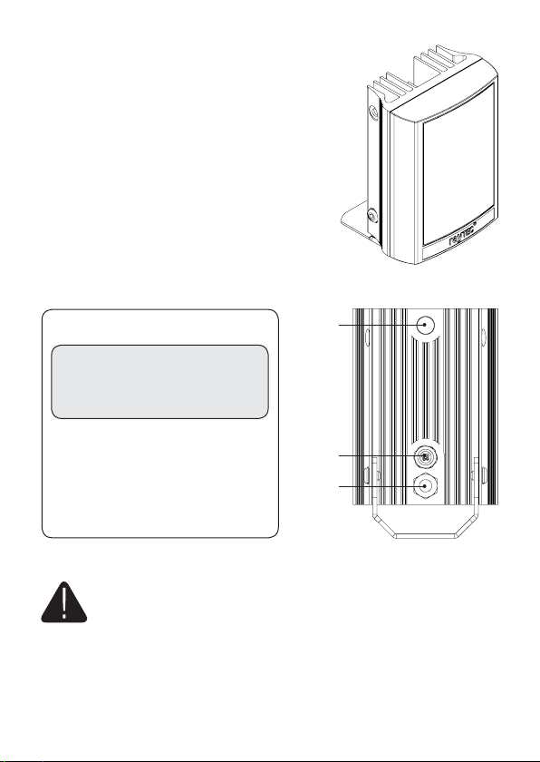
Wiring - six core cable
Photocell
DC AC
Black wire - ~
Red wire + ~
White & Yellow wires =
Photocell following contact.
Volt free output. Non polarity sensitive.
Orange & Purple wires =
Telemetry input Volt free/dry contact or
TTL input
2 www.rayteccctv.com UK / Europe Tel: +44 (0) 1670 520055
(See Page 4 - Step 5 for more details)
• IR Variants
CAUTION - IR emitted from this product – Risk Group 2. Do not stare at the lamp.
Avoid exposure or use appropriate shielding / eye protection. Risk Group 2 for
cornea / lens infrared hazard.
At a distance of more than 1500mm for all products the unit is in the exempt
group.
• White Light Variants
Risk Group 1 classification. Do not stare at the lamp.
Cable
Breather
Gland
Americas Tel: +1 613 270 9990
Page 3
Factory Default Set-Up:
35˚ Beam Angle
Max 100% Power
Telemetry Input - closed
Photocell sensitivity - MID
Status LEDs – ON
Programming function will auto-disable after 4 weeks
VARIO Complete Set up and Installation
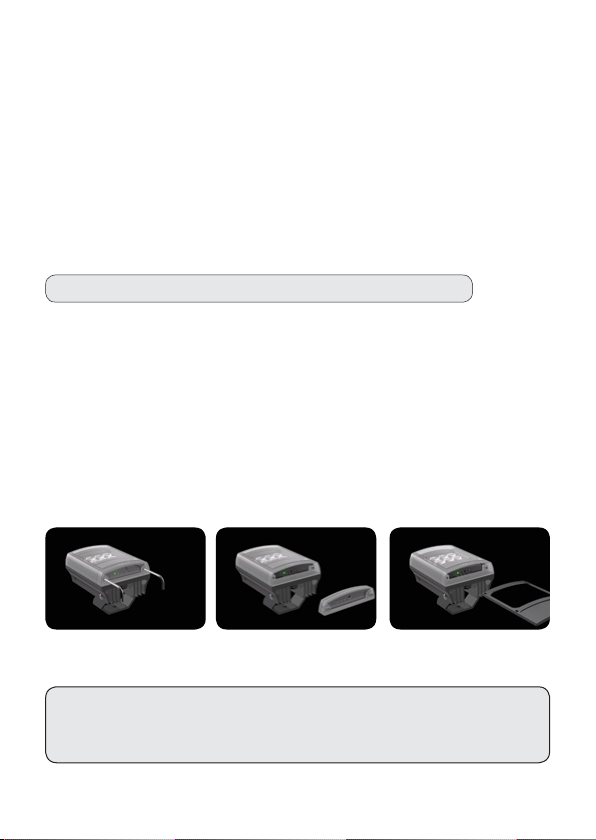
Step 1. Select different beam angle – if required
VARIO is factory set and delivered with a 35˚ beam width angle.
To alter to 10˚, simply remove interchangeabIe holographic diffuser (IHD) lens.
To alter to 60˚, replace with other IHD lens supplied.
Other angle IHD lenses are available to order: 80˚ and 120˚.
All IHD lenses will be clearly marked with the angle which they will produce when
inserted into VARIO.
Please handle IHD lenses with care – and do not touch optical film.
Only 1 IHD lens can be inserted into the product at anytime. The product cannot
accommodate mutliple IHD lenses at the same time.
We would recommend that power is turned off when replacing IHD lenses.
Remove base plate from VARIO unit using 2.5mm allen/hex key. Insert required IHD
lens and re-attach base plate firmly ensuring gasket is correctly located.
IMPORTANT NOTE: Ensure base plate is securely located, the gasket is
correctly located and the screws correctly fastened to ensure and maintain IP66
rating of the product.
Americas Tel: +1 613 270 9990
3www.rayteccctv.comUK / Europe Tel: +44 (0) 1670 520055
Page 4
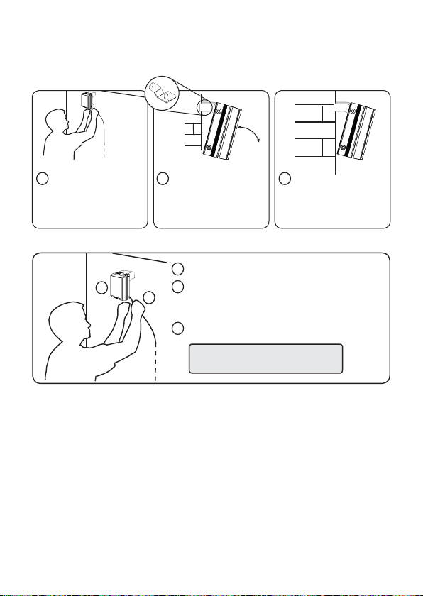
Step 2. Mounting Illuminator
VARIO is delivered as standard with bracket at the bottom of the unit. This can be
moved to top the of unit if required. See page 6 for optional brackets
TARGET
1 2 3
Position illuminator
adjacent to camera and point
towards scene (Optional
night set-up for optimum
image performance)
Adjust vertical position of
lamp to ensure full field of
view illuminated
Tighten all fixings
Step 3 & 4. Connect to low voltage power supply and input 12/24 AC/DC
1
2
Mount illuminator
1
Connect Illuminator to low voltage power supply:
2
Installers can extend or reduce lead length using
appropriate cable and weather proof box
Input 12-24V DC/ 24V AC
3
Note: Red = positive
Black = negative
Step 5. Telemetry Input (Orange & Purple)
As default will be wired together for standard photocell controlled on/off operation.
If required to be activated by PIR or alarm system, connect to appropriate, volt-free
input or TTL. Telemetry Input for remote switch or input. Volt free input/dry contact:
Non polarity sensitive, short circuit = light on
TTL input: Orange = TTL +ve, Purple = TTL –ve (GND)
0V = Light on, 3V = Light off
Step 6. Photocell following output (White & Yellow)
Volt free output - normally open (day) to normally closed (night). Connect direct to
camera if required to control switchover of day/night cameras.
4 www.rayteccctv.com UK / Europe Tel: +44 (0) 1670 520055
Americas Tel: +1 613 270 9990
Page 5

VARIO Remote Controller (VRC)
Optional Accessory
Full instructions provided with VRC when supplied
Photocell Adjust
To select 3 different photocell sensitivity
levels to accommodate different
operational requirements.
Power Select
Quick and easy selection
of 5 accurately defined
power settings, 1=20%,
2=40%, 3=60%, 4=80%
5=100%. Provides
exact amount of light
required for the scene
requirements.
Photocell Disable
Lamp operates from
telemetry input only
Selects telemetry Input.
Disable Remote
Control Set-Up
Must be depressed for
4 seconds to lock-in
settings and prevent
further alterations.
LED Status Indicator
Turns status LED’s On or Off
Timer Setting
The timer function allows the
illuminator to be triggered
via the telemetry input and
remain on for a pre-defined
period of time.
30 mins
10 mins
3 mins
1 min
Timer disable
Selects dimming
function on
telemetry wires.
Restores Factory
Default Settings.
Must be depressed
for 4 seconds.
Americas Tel: +1 613 270 9990
5www.rayteccctv.comUK / Europe Tel: +44 (0) 1670 520055
Page 6

Feedback system
VARIO LED Status Indicators (in Programming Mode)
SOLID GREEN status LED indicates unit has power
applied.
FLASHING GREEN status LED indicates a problem
with the remote control IR receiver. The maximum
remote operating distance is 8m (26ft).
FLASHING AMBER status LED indicates unit is in
programming mode. SOLID AMBER indicates unit
receiving valid command from remote control device.
SOLID RED status LED indicates an internal LED fault,
and a FLASHING RED status LED indicates that there
is a problem with the input voltage.
the voltage problem has been corrected, the user must disable
remote control set-up or power the unit on and off to stop the
RED status LED flashing)
VARIO LED Status Indicators (in Normal Operating Mode)
SOLID GREEN status LED indicates unit has power
applied.
FLASHING GREEN status LED indicates a problem
with the remote control IR receiver. The maximum
remote operating distance is 8m (26ft).
SOLID AMBER status LED (non flashing) indicates a
problem with the input voltage level.
(Please note – once the voltage problem has been corrected,
the user must disable remote control set-up or power the unit on
and off to extinguish the AMBER status LED)
(Please note – once
GREEN
AMBER
RED
GREEN
AMBER
SOLID RED status LED indicates an internal LED fault.
RED
6 www.rayteccctv.com UK / Europe Tel: +44 (0) 1670 520055
Americas Tel: +1 613 270 9990
Page 7

Standard Bracketry (not to scale, dimensions rounded to nearest mm)
VARIO 2 series VARIO 4 series
52mm
47mm
51mm
VARIO 8 series
53mm
104mm
Optional Bracketry (not to scale)
Wall Mount
56mm
72mm
53mm
53mm
Dome MountPtz Mount
Pole Mount
Americas Tel: +1 613 270 9990
7www.rayteccctv.comUK / Europe Tel: +44 (0) 1670 520055
Page 8

VARIO Specifications
Infra-Red Series & White-Light Series
VARIO i8 VARIO w8 VARIO i4 VARIO w4 VARIO i2 VARIO w2
220m (10˚) 150m (10˚) 120m (10˚) 90m(10˚) 65m (10˚) 50m (10˚)
120m (35˚) 80m (35˚) 65m (35˚) 55m (35˚) 45m (35˚) 35m (35˚)
Max. Distance
Model dependent
Consumption
~
Input 12-24V AC or DC 12-24V AC or DC 12-24V AC or DC
Weight 1.8kg (4lbs) 1kg (2.2lbs) 650g (1.4lbs)
Environment IP66 IP66 IP66
65m (60˚) 45m (60˚) 45m (60˚) 30m (60˚) 30m (60˚) 20m (60˚)
45m (80˚) 30m (80˚) 30m (80˚) 20m (80˚) 20m (80˚) 15m (80˚)
30m (120˚) 20m (120˚) 20m (120˚) 15m (120˚) 15m (120˚) 10m (120˚)
48W max 24W max 12W max
Dimensions
L x W x D
Cable Length 2.5m 2.5m 2.5m
135 x 180 x 68.2 mm
(5” x 7” x 3.2”)
100 x 135 x 66mm
(4” x 5” x 2.5”)
75 x 100 x 64mm
(3” x 4” x 2.5”)
Standards:
Radiated/Conducted Emissions: EN55015; EN55022; EN61547; FCC
Radiated/Conducted Immunity: EN55015; EN55022; EN61547; FCC
EN50130-4
EN60529-1
IEC/EN 62471
8 www.rayteccctv.com UK / Europe Tel: +44 (0) 1670 520055
Americas Tel: +1 613 270 9990
Page 9

VARIO Troubleshoot
Ensure all tests are undertaken by a qualified, trained engineer.
Ensure safe working practices are followed at all times.
Step 1: Basics
• Check polarity of Lamp connection red=+ve, black=-ve
• Ensure power is 12-24V AC or DC
• Ensure telemetry wires are shorted out or closed contact input (zero volt) is applied
• Check photocell is working. Cover photocell fully, light should turn on. It is
sometimes difficult to see Infra-Red lamps working in high brightness conditions.
• Ensure power supply is suitably rated to product - check page 8 for specifications
• If longer cables used, ensure sufficient voltage is provided to allow for drops
across the cable
If OK…
Step 2: Lamp Test
• Check current is being drawn – amount of current will depend on power setting of
unit. Please note – use appropriate multimeter depending on how the unit is being
powered (AC or DC)
To test this you must ensure photocell fully covered (or disabled using optional
VARIO remote controller) and ensure telemetry wires are shorted out or closed
contact input (zero volt) is applied
Americas Tel: +1 613 270 9990
9www.rayteccctv.comUK / Europe Tel: +44 (0) 1670 520055
Page 10

Step 3: Set up camera, lens, and illumination
• Check model number to Raytec performance specification to ensure required
distance is achievable;
- Check unit is set to max power
- Check orientation of unit and ensure it is pointing in correct direction
- Check angle of unit (Holographic lens) – Too narrow may cause hot spots
and the aperture of the camera lens to close down. Too wide and there
may be insufficient light on scene and light going where it is not needed.
• Check the LED status indicator – if a flashing red light is visible in programming
mode, please check the input voltage of the unit. The feedback system will respond
differently depending on what mode the unit is in (see below)
Programming mode – (AMBER LED flashes 1 second on/1 second off)
SOLID GREEN - Power Applied
FLASHING GREEN - Remote IR receiver problem
SOLID RED - Internal LED Fault Detected
FLASHING RED - Voltage supply problem detected
(Please note – once the voltage problem has been corrected, the user must disable remote
control set-up or power the unit on and off to stop the red status LED flashing)
SOLID AMBER - Valid command being received, this remains lit for the duration
that the button on the remote is held. After a valid command has been received the
Amber LED will continue to flash
Normal operating mode
SOLID GREEN - Unit powered up and operating normally
FLASHING GREEN - Remote IR receiver problem
SOLID RED - Internal LED fault detected
SOLID AMBER - Voltage supply problem detected
(Please note – once the voltage problem has been corrected, the user must disable remote
control set-up or power the unit on and off to extinguish the AMBER status LED)
10 www.rayteccctv.com UK / Europe Tel: +44 (0) 1670 520055
Americas Tel: +1 613 270 9990
Page 11

• Check unit is responding to remote. If not..
- Programming may be disabled. Turn power off/on to ensure unit returns to
programming mode.
- Status indicators may be turned off. Turn on with remote. This can be done
even if programming has been disabled
- In extreme sunlight conditions, distance between remote and unit may need to
be reduced
- Battery failure. Check battery on remote (CR2025). Test 3 volt battery, replace if
necessary. Ensure battery has clean contacts.
- Remote failure. Test with new remote.
Step 4: Call Raytec for further assistance
Note down:
• Model and serial number of illuminator
• Camera make and model
• Lens make and model
If the Raytec lamp or remote control is still not delivering the required
performance, please contact us for further assistance:
UK / Europe Tel: +44 (0) 1670 520055
Americas Tel: +1 613 270 9990
Raytec Warranty
Please register you Raytec LED Illuminator(s) for its 5 year warranty by visiting
www.rayteccctv.com/products/warranty-card
Americas Tel: +1 613 270 9990
11www.rayteccctv.comUK / Europe Tel: +44 (0) 1670 520055
Page 12

VA/15/1.1
UK / Europe
T: +44 (0) 1670 520055
F: +44 (0) 1670 819760
sales@rayteccctv.com
Americas (Toll Free)
T: +1 888 505 8335
ussales@rayteccctv.com
www.rayteccctv.com
 Loading...