

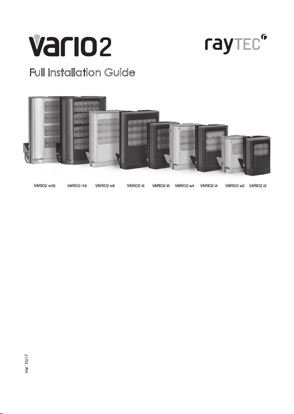
Page 1
Quick Start
180 x 277 x 75mm
7”x11”x2.9”
135 x 180 x 68mm
(5”x7”x3”)
100 x 135 x 66m
4”x5”x2.5”)
75 x 100 x 64mm
3”x4”x2.5”)
Safety Information:
White Light and IR Variants (850nm & 940nm)
Caution – Risk Group 2. Avoid Exposure / use protection.
See Safety Information in FULL Instruction Guide for details.
Box Contents:
VARIO2 Illuminator with 35° ILS fitted, spare 60° beam angle ILS, User Guide
(ILS: Interchangeable Lens System)
Optional Accessories: Remote Controller for additional programming,
80˚ beam angle ILS, 120˚ beam angle ILS, Bracketry
Factory Default Set-Up:
35˚ Beam Angle ILS, Max 100% Power
Telemetry Input – closed, Photocell sensitivity – MID
Status LEDs – ON, No PIN Set
Unit will change from Programming Mode to Operating Mode after 7 Days (or 30
minutes after last press of manual buttons)
VARIO2 Specifications Table:
i16 w16 i8 w8 i6 i4 w4 i2 w2
100W
84W
max
max
48 24 12 9 12 6 6
Ver.10/17
Consumption
Input 24V AC/DC 12/24V AC/DC 12/24V AC/DC 12/24V AC/DC
Weight 3.1kg (6.8lbs) 1.65kg (3.61lbs) 950g (2.1lbs) 600g (1.3lbs)
Number of
LED’s
Environment IP66 IP66 IP66 IP 66
Dimensions
Cable Length 2.5m 2.5m 2.5m 2.5m 2.5m 2.5m 2.5m 2.5m 2.5m
46W
max
42W
max
25W
max
13W
max
24W
max
10W
max
11W
max
Page 2
Wiring:
Important Note : Ensure base plate is securely located, the gasket is
1. Mount Illuminator
2. Connect Illuminator to low voltage input 12-24V AC/DC
IMPORTANT: For Vario 16 variants : 24V only AC/DC
3. Complete configuration, wiring and final set-up using manual push buttons on
the illuminator or VARIO Remote Controller (VRC) - VRC is an optional
accessory
Black Wire = Negative (-ve)
Red Wire = Positive (+ve)
White & Yellow wires = Photocell following contact, Volt free output, Non polarity
sensitive
Orange and Purple Wires = Telemetry input Volt free / dry contact or TTL input
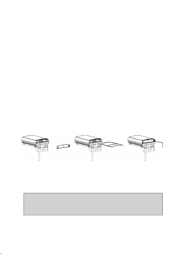
Lens Selection:
VARIO is factory set and delivered with a 35˚ beam width angle.
To alter to 10˚, simply remove interchangeable lens (ILS).
To alter to 60˚, replace with other ILS lens supplied.
Other angle ILS lenses are available to order: 80˚ and 120˚.
Please handle ILS lenses with care – and do not touch optical film.
Use 2.5mm Allen/hex key. Re-attach base plate securely ensuring gasket is correctly
located.
correctly located and the screws correctly fasten ed to ensure and
maintain IP66 rating of the produ ct
Page 3
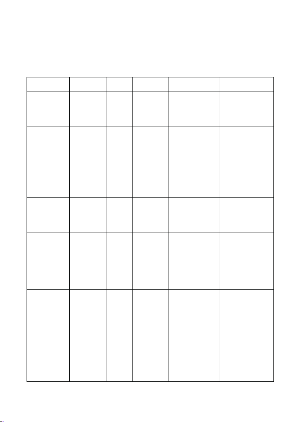
Manual Button Operation
Action
Required
Step1 :
LHS Button
LHS
LED
Step 2 :
RHS Button
RHS
LED
Comment
Power Adjust
1 x Push
Solid
Each Push
levels
Green flashes
power (1 flash)
Photocell
2 x Push
Solid
Each Push
Green flashes
disabled.
Status
3 x Push
Solid
Each Push
Off
On – Green
Factory Re-
1 x Long
Flashing
Push and
Solid Red – After
Reverts to
set
Disable
1 x Long
Flashing
Push to
Disable – Red
Reverts to the
Buttons are accessed by removing the base plate at the bottom of the unit.
The number of button pushes indicated below are based on the user starting
with the illuminator in either programming or operating mode.
Red
cycles
through
power
indicate level.
High power (5
flashes) to Low
Adjust
Indicator
LEDS On / Off
set (Does not
Re-set PIN)
Remote
Control
Push
(4
Seconds)
Push (4s),
then 1 x
short Push
Green
Amber
Red –
Green
cycles
through
photocell
levels
cycles
between
On and
Hold until
both LEDs
flash
Amber
cycle
Disable /
Enable
indicate 3
sensitivity
settings:
Low: 1 Flash
Med: 2 Flashes
High: 3 Flashes
Solid Red for
Photocell
Off - Red
4s both LEDs
Flashing Amber
Enable - Green
Programming
Mode unless a
PIN is present. If a
PIN is present
reverts to original
mode before re-
Mode requested
unless a PIN is
present. If a PIN is
present and you
are in Operating
Mode you
cannot change
to Programming
Mode
Page 4
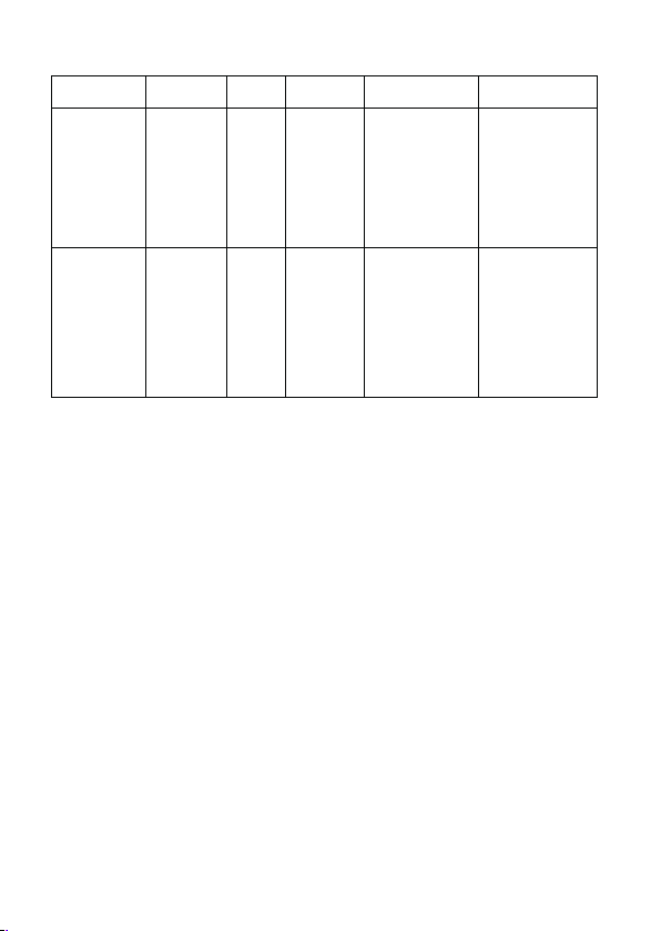
Action
Required
Step1 :
LHS Button
LHS
LED
Step 2 :
RHS Button
RHS
LED
Comment
Disable /
Enable
1 x Long
Flashing
Push to
Disable – Red
Buttons will be
selection is made
required
Full Re-set
Keep both
Flashing
Keep both
Flashing Amber
Illuminator will
Manual
Buttons
Push (4s),
then 2 x
short Push
Amber
cycle
Disable /
Enable
Enable - Green
Disabled 30
minutes after this
– This is to allow
the user to reenable manual
buttons if
(including
PIN re-set)
buttons
depressed
during
power up –
LEDs will
both flash
Amber
Amber
then
solid
green
after
button
release
buttons
depressed
during
power up
– LEDs will
both flash
Amber
then Flashing
Amber after
button release
The illuminator has two modes;
(1) Programming Mode when the remote control can be used and
(2) Operating Mode when most of the remote control functions are disabled.
The only remote control functions that can be used in Operating mode are;
Enable/Disable Status LEDs, Disable Manual Buttons and PIN entry.
Manual Buttons are always available in programming mode or if they have been
disabled, they can be enabled in programming mode.
Manual Buttons are available in operating mode, provided they have not already
been disabled.
The number of button pushes indicated above are based on the user starting with
the illuminator in either programming or operating mode.
If no buttons are pressed within 2 minutes then the illuminator will automatically
default back into the previous mode it was in – programming or operating mode.
revert to
Programming
Mode, Full
factory default
including No PIN
Page 5
Pressagainfor 4secondsto
disablemanualbuttons–
ThiswillNOTr emove
mustbedon ewithin5
minutesofre motedisable
PINifpres ent
Page 6
Remote Control Operation
Action
Required
Available
Mode
Step1
Step 2
LHS
LED
RHS
LED
Comment
Disable
Programming
Press
N/A
Solid Green
Flashing Amber to
Illuminator will go
Disable
Operating
Press
N/A
Solid Green –
Off to Solid Amber,
Must be done
Create or
Programming
Press
Enter
Green to
Solid Amber to
required.
After PIN created
Enter
Operating
Press
Enter
Green –
Solid Amber to
If invalid PIN
Delete PIN
Programming
Press
Press
Green –
Solid Amber to
After PIN deleted
PIN set and Manual Button Disable / Enable
Remote
Manual
Buttons
Change
PIN
Mode
Mode
Mode
<Disable
Remote
Control>
button on
VRC for 4
seconds
<Disable
Remote
Control>
button on
VRC for 4
seconds
<Status
Button>
for 4
seconds
valid PIN
charact
ers
x 4
After 4
seconds
Flashing Red
(Returns to
Solid Green
after button
release)
Intermittent
Flashing Red /
Green
Solid Amber to Off
then after 4
seconds Flashing
Red
(Returns to Solid
Green after button
release)
Flashing Red
Flash qty counts
down the No. of
characters
to Operating
Mode. RHS LED
turns Off when in
Operating Mode.
within 5 minutes
of Disabling
remote (as
above) Change
will take effect
after 30 minutes
Illuminator goes
to Programming
Mode (Standard
LED indication)
existing PIN
Mode
Mode
For full PIN function detail (inc valid PIN characters) – see FULL instruction
guide
<Status
Button>
for 4
seconds
<Status
Button>
for 4
seconds
valid PIN
charact
er
x 4
<Re-Set>
button 4
times
Intermittent
Flashing Red /
Green
Intermittent
Flashing Red /
Green
Flashing Green
Flash qty counts
down the No. of
characters
required
Flashing Red Flash
qty counts down
the No. of
characters
required
entered both
LEDs flash red and
unit will stay in
Operating Mode
Illuminator goes
to Programming
Mode (Standard
LED indication)
Page 7
LED Status Indicators:
Lefthandside
Righthandside
Lefthandside
Righthandside
Programming Mode and Operating Mode
On first power up (Factory Default) the illuminator automatically enters
Programming Mode. It will then time out automatically after 7 Days to Operating
Mode unless the user actively disables the remote control or uses the manual
buttons in which case Operating Mode will start 30 minutes after the last manual
button press. The LED Indicators feedback the mode you are in. (They are also
used for PIN or Manual Button Control Modes – please see tables / FULL Instruction
Manual)
(LHS)Button
(LHS)LED
(RHS)LED
During Programming Mode and Operating Mode the two LED’s indicate the
following status :
• LHS SOLID GREEN: Power Applied
• LHS FLASHING GREEN: Remote control IR received problem
• RHS FLASHING AMBER: Indicates unit is in programming mode
• RHS SOLID AMBER: Indicates that a valid command is being received
• LHS FLASHING RED: Voltage supply problem detected
• LHS SOLID RED: Illuminator LED fault detected
All functions of the remote control and buttons are available in Programming
Mode.
The only function of the Remote Control available during Operating Mode is
LED Status Indicators Enable/Disable, entering a PIN or disabling manual buttons
(if done at the same time as disabling the remote – see FULL Instruction Manual
(Programming Mode Only)
(Programming Mode Only)
(RHS)Button
Page 8
RESET:
Settings Re-set : Pressing and holding the RESET BUTTON on the remote control
or using the manual buttons to complete a RESET will restore the factory
settings to the illuminator. Note : It will not remove a PIN if one is present.
Full Re-set : Re-cycling the power whilst pressing both manual buttons will
restore factory settings and remove a PIN if one is present.
Both indicator LEDs flash amber for both above re-sets when complete.
VARIO2 Quick Troubleshoot:
Ensure all tests are undertaken by a qualified, trained engineer. Ensure safe
working practices are followed at all times.
• Check polarity of illuminator connection red=+ve, black=-ve
• Ensure power is 12-24V AC or DC (For Vario 16 variants : 24V only AC or DC )
• Ensure telemetry wires are shorted out or valid telemetry input (zero volt or
TTL) is applied and correctly wired
• Check photocell is working. Cover photocell fully, light should turn on if valid
telemetry input. It is sometimes difficult to see Infra-Red illuminators working in high
brightness conditions.
• Ensure power supply is suitably rated to product - check page 1 fo
specifications
• If longer cables used, ensure sufficient voltage is provided to allow for drops
across the cable
For in-depth Troubleshoot, see Full Instructions, or contact Raytec.
r
UK / Europe
Tel: +44 (0) 1670 520055
sales@rayteccctv.com
Americas
Tel: +1 613 270 9990
Toll Free: +1 888 505 8335
ussales@rayteccctv.com
www.rayteccctv.com
Page 9
Full Installation Guide
Contents :
Page 2 Box Contents and Safety Information
Page 3 Short Guide and Factory Defaults
Page 6 LED Status Indicators – Feedback System
Page 8 VARIO Remote Controller (VRC)
Page 10 PIN Function Detail
Page 12 Manual Control Buttons
Page 17 Disabling Manual Buttons
Page 18 Power Up Functionality ; Re-Set Options
Page 19 Standard Bracketry
Page 20 Specifications Table
Page 21 Troubleshooting
Ver. 10/17
Page 10
Box Contents :
VARIO2 Illuminator , spare 60° beam angles ILS
(ILS: Interchangeable Lens System)
Accessories (Optional) :VARIO Remote Control for additional Programming;
VARIO2 Enhancements
• Increased Distance
• Default time for illuminator to go into Operating Mode reduced
• PIN function for enhanced security
• Manual Control added – Push Buttons Accessible on the illuminator
• Improved RESET Options
• The 3 single colour feedback LED’s have been replaced with
2 tri-colour LED’s
80˚ beam and 120˚ beam angle ILS; Bracketry
SafetyInformation
Eye Safety : IR Variants (850nm and 940nm)
Caution – IR emitted from this product EN62471 Risk Group 2
Do not stare at the lamp. Avoid exposure or use appropriate
shielding / eye protection. Risk Group 2 for cornea / lens
infrared hazard. For VAR-i2, VAR-i4, VAR-i6 and VAR-i8
variants hazard distance is 1500mm. For VAR-i16 hazard
distance is 1840mm. Max IR EHV (Exposure Hazard Value) :
69% of Risk Group 2 Limit at 200mm from the lamp.
Eye Safety : White Light Variants
Caution – EN62471 Risk Group 2 Classification - Possible
hazardous optical radiation emitted from this product. May
be harmful to eyes, do not stare at the lamp. For VAR-w2,
VAR-w4, VAR-w8 Hazard distance is 1500mm. For VAR-w16
hazard distance is 1840mm. Max WL EHV (Exposure Hazard
Value) : 68% of Risk Group 2 Limit at 200mm from the lamp.
The Illuminator is Class lll for insulation
Illuminators are suitable for use Outdoors and Indoors
2
Page 11

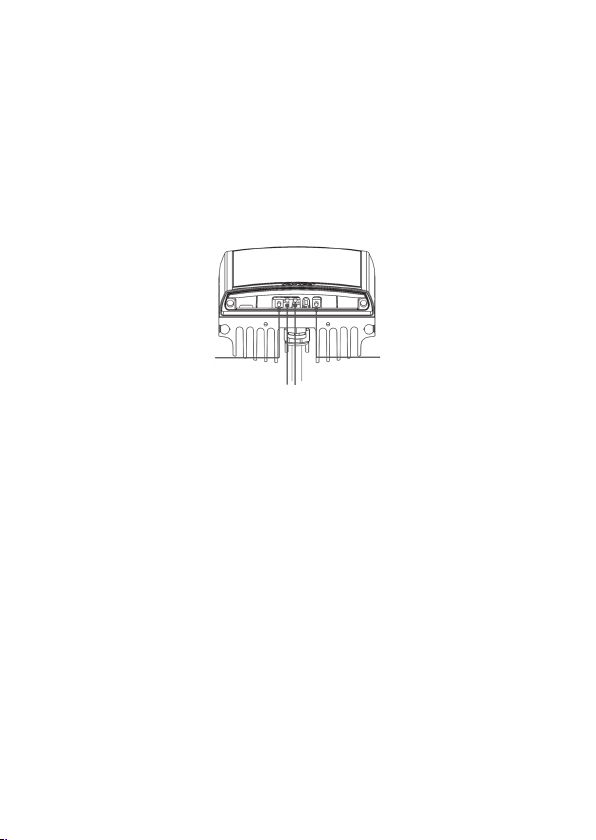
Installation Steps:
Wiring–sixcorecab le
DC AC
Photocell
Cable
Breather
Gland
1. VARIO2 is factory set and delivered with a 35˚
beam width.
To alter to 10˚, simply remove interchangeable
lens (ILS). See page 4 for detailed instructions
To alter to 60˚, replace with other ILS lens
supplied.
2. Mount Illuminator
3. Connect Illuminator to low voltage input 12-24V
AC/DC (For Vario 16 variants : 24V AC or DC only)
4-6. Complete configuration, wiring and final set-up using manual push
buttons on the illuminator or VARIO Remote Controller (VRC)
- VRC is an optional accessory
Black Wire - ~
Red Wire + ~
White&Yellowwires=
Photocellfollowingcontact,
Voltfreeoutput,Nonpolaritysensitive
OrangeandPurpleWires=
TelemetryinputVoltfree/drycontactor
TTLinput(seePage5and6formoredetail)
The external cable cannot be replaced. If it is damaged and the customer
is unable to shorten and re-use the cable, the illuminator must not be
powered.
3
Page 12

Factory Default Set-Up:
VARIO is factory set and delivered with a 35˚ beam width angle.
Important Note : Ensure base plate is securely located, the gasket is
35˚ Beam Angle ; Max 100% Power
Telemetry Input – closed ; Photocell sensitivity – MID
Status LEDs – ON ; No PIN Set ; Manual Button Control Enabled
Programming function will auto-disable after 7 Days
VARIO2 Complete Set up and Installation
Step 1. Select different beam angle – if required
To alter to 10˚, simply remove interchangeable lens (ILS).
To alter to 60˚, replace with other ILS lens supplied.
Other angle ILS lenses are available to order: 80˚ and 120˚.
All ILS lenses will be clearly marked with the angle which they will produce
when inserted into VARIO2.
Please handle ILS lenses with care – and do not touch optical film.
Only 1 ILS lens can be inserted into the product at anytime. The product
cannot accommodate multiple ILS lenses at the same time.
We would recommend that power is turned off when replacing ILS lenses.
Remove base plate from VARIO2 unit using 2.5mm allen/hex key. Insert
required ILS lens and re-attach base plate securely ensuring gasket is
correctly located.
correctly located and the screws correctly fastened to ensure and
maintain IP66 rating of the product
4
Page 13

Step 2. Mounting Illuminator
VARIO2 is delivered as standard with bracket at the bottom of the unit.
This can be moved to the top of the unit if required. See page 18 for
optional brackets
Step 4. Telemetry Input (Orange & Purple)
As default the telemetry input will be wired together so that the unit turns
on/off automatically via the photocell. If required to be activated by PIR
or alarm system, connect to appropriate, volt-free or TTL input. Volt free
input/dry contact: Non polarity sensitive, short circuit = light on
TTL input: Orange = TTL +ve, Purple = TTL –ve (GND) 0V = Light on, 3V =
Light off
5
Page 14

Step 5. Photocell following output (White & Yellow)
Volt free output - normally open (day) to normally closed (night).
Connect direct to camera if required to control switchover of day/night
cameras.
Step 6. Programme using optional VARIO Remote Control (VRC) or the
manual control buttons.
Step 7. Set PIN (If Required) (Can only be done with the optional VARIO
Remote Control(VRC)
LED Status Indicators- Feedback system :
There are two tri-coloured LEDs visible on the base of the VARIO2
illuminator. The two LEDs provide important operating and status
information.
The LED Indicators also give feedback if you are using the
Remote, PIN Function or Manual Control Modes – Please see
Pages 10 to 17 for detail on the LED status indicator feedback for
these functions
6
Page 15

Programming Mode and Operating Mode
On powering up the illuminator, it automatically enters
programming mode to allow the user to adjust set-up and
operation. The programming mode automatically times out after
7 Days or until the user actively disables the remote control or the
unit times out 30 minutes after any press of the manual buttons on
the illuminator.
During Programming Mode and Operating Mode the two LED’s
indicate the following status :
LHS SOLID GREEN: Power Applied
LHS FLASHING GREEN: Remote control IR receiver problem (Max
RHS FLASHING AMBER: Indicates unit is in programming mode
RHS SOLID AMBER: Indicates that a valid command is being
LHS FLASHING RED: Voltage supply problem detected
LHS SOLID RED: Illuminator fault detected
All functions of the remote control and buttons are available in
Programming Mode.
The only function of the Remote Control available during
Operating Mode is LED Status Indicators Enable/Disable, entering
a PIN or disabling manual buttons (if done at the same time as
disabling the remote – see P.8)
Factory Default: On initial power-up, Programming Mode.
VRC distance is 8m (26ft)
(Programming Mode Only)
received from the remote (Programming
Mode Only)
7
Page 16

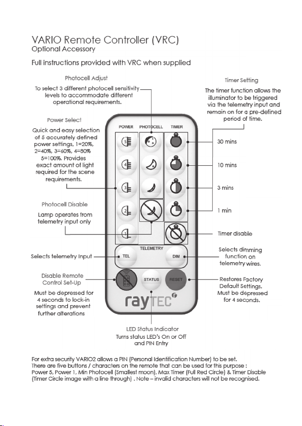
VARIO Remote Controller (VRC) :
Pressagainfor 4secondsto
Optional Accessory
Full instructions provided with VRC when supplied
disablemanualbuttons–
mustbedon ewithin5
minutesofre motedisable
Note : Reset button will not remove a PIN if one is present
Note : Unless detailed as part of the functionality, if an invalid or
blocked command is attempted, both LEDs will flash RED
8
Page 17

Extra VRC Functionality :
Thismustbedonewithin5
- PIN Function
For extra security VARIO2 allows a PIN (Personal Identification
Number) to be set for each lamp
The PIN is set by using the Vario Remote Control (VRC). There are
five buttons / characters on the remote that can be used for this
purpose.
minutesofd isabling remote
Note : Unless detailed as part of the functionality, if an invalid or
blocked command is attempted, both LEDs will flash RED
9
Page 18

PIN Function Detail :
The PIN is set by using the Vario Remote Control (VRC). There are five
buttons / characters on the remote that can be used for this purpose.
They are Power 5, Power 1, Min Photocell (Smallest moon), Max Timer (Full
Red Circle) & Timer Disable ( Timer Circle image with a line through) .
Note – invalid characters will not be recognised.
To create a PIN, press STATUS BUTTON for 4 seconds. LHS LED will flash
RED/GREEN. This indication will always show that you are in PIN mode.
RHS LED FLASHING RED shows there you are in PIN set mode. The number
of flashes indicates how many characters are required to complete the
PIN entry. There are four characters to be entered to successfully set up a
PIN.
As you enter the characters, the number of flashes will decrease until all
characters are entered. Note, illegal characters will not be recognised
and will not reduce the number of flashes. When the PIN is set the
illuminator will revert to Programming Mode.
When a PIN is Set :
Using the remote you can access the illuminator settings from operating
mode by entering the PIN.
You cannot access Programming Mode by power re-cycling only.
In operating mode, if you want to go back into programming mode
simply enter your PIN. To do this, press STATUS BUTTON for 4 seconds. LHS
LED will flash RED/GREEN to show you are in PIN mode. RHS LED FLASHING
GREEN shows that a PIN has been previously set. As you input the four
correct characters the number of flashes will reduce and you will be
returned to programming mode.
If legal characters but not the correct sequence of characters is entered
the number of flashes will still reduce and after 4 characters have been
entered an error will be shown by both LED`s flashing RED.
If an illegal character is used when entering a pin, it will be ignored and
the PIN character count will not reduce.
10
Page 19

To delete an existing PIN you first need to be in Programming Mode by
entering your PIN. Once in Programming Mode, press STATUS BUTTON for
4 seconds to go into PIN set mode. LHS LED will flash RED / GREEN and
RHS LED FLASHING RED. Instead of entering one of the known legal
characters press the RESET BUTTON four times. The illuminator will return to
programming mode. Note – if you delete the PIN and the illuminator
times out into operating mode, you will not be able to go back to
programming mode without recycling the power.
*Note - If you forget your pin and need to make adjustments to the
illuminator you need to do full Re-set. This requires power recycling whilst
pressing the two manual control buttons at the same time. This will restore
factory default settings AND remove the previously programmed PIN.
Both LEDs will flash AMBER to signify that the process has been
completed.
*Note – If you need to check if a PIN is set up, in Operating Mode hold
the status button down for 4 seconds and both LEDs flash RED, this means
there is no PIN present.
11
Page 20

Manual Control – Buttons :
The two manual control buttons gives a wide selection of user control :
1.
Power Control – 100%, 80%, 60%, 40%, 20% of maximum. (Factory
Default is 100%)
2. Photocell Control – 3 levels, 25 Lux on, 50 Lux off, 10 Lux on 30 Lux off,
5 Lux on 15 Lux off and photocell disable.
3. Turn LED indicators on & off
4. Illuminator Reset Options
5. Disable Remote Control and enter Operating Mode or Enable
Remote Control and enter Programming Mode
6. Button Enable & Disable
12
Page 21

Manual buttons can be accessed by removing the base cover of the
illuminator
The buttons are active in both programming mode and operating mode
regardless of whether a PIN is present or not unless you have previously
disabled the manual buttons
As soon as manual button mode is entered by pressing the Left Hand
Button, the standard LED indicators will be disabled and will indicate a
new set of information, Standard LED indicators are enabled after exiting
manual button modes.
Note : Unless detailed as part of the functionality, if an invalid or
blocked button push is attempted, both LEDs will flash Red
Mode Selection by using LHS Button :
A momentary press of LHS button turn LHS LED solid RED and enters the
user into the Illuminator Settings Modes.
In these modes you can change the following settings :
-
Power Level
- Photocell sensitivity
- Indicator LED status (On or Off)
A continuous 4 second press of the LHS button turns LHS LED flashing RED
and enters the user into the Illuminator Security Modes.
In these modes you can change the following Security/Configurations :
- Illuminator Re-set
- Disable Remote Control and enter Operating Mode or Enable
Remote Control and enter Programming Mode
- Manual Button Enable / Disable
*Note – If the status indicator LEDs are disabled and you use the manual
buttons the indicator LEDs will still illuminate accordingly
13
Page 22

Manual Setting / Level Indication using RHS Button :
The RHS BUTTON will only have an effect if you have selected a mode
using LHS Button – pressing RHS Button without previously pressing LHS
Button will have no effect on the Illuminator operation – it is used to
control the setting for the mode chosen by LHS Button
When you select a mode using LHS BUTTON, the LHS LED will confirm
which mode you are in and RHS LED will show the current setting / level
of that mode for the Illuminator.
Sequential presses of RHS BUTTON will take you through the available
options to get to the required setting you want within that mode. The
Illuminator will stay at this setting / level providing you do not push the
RHS BUTTON again. Once you have reached the required setting as
shown in the following text, EITHER press the LHS BUTTON to cycle through
the modes until LHS LED extinguishes showing that you are at the end of
the mode loop OR you can also wait 2 minutes for the illuminator to time
out and the value shown by RHS LED will be stored into the illuminator
memory.
The settings programmed will be retained on power recycling unless a
reset has been performed, in which case the factory defaults will be
applied.
14
Page 23

Illuminator Settings Mode Detail :
Enter this mode by a momentary press of LHS button to turn LHS LED solid
RED.
Pressing the LHS button again will turn the LED solid GREEN and pressing a
third time will turn the LED solid AMBER. Each of these colours indicates
which setting mode you are in.
A further momentary press of LHS Button will exit from the mode entry,
both LEDs will go out for 1 second and then return to the standard
indication of either operating mode or programming mode (depending
on which mode the Illuminator was in previously before selecting manual
controls.
The following modes are available :
Power Level Mode (LHS LED : Solid RED)
RHS LED :
20% Power Setting: 1 Flash GREEN
40% Power Setting: 2 Flashes GREEN
60% Power Setting: 3 Flashes GREEN
80% Power Setting: 4 Flashes GREEN
100% Power Setting: 5 Flashes GREEN
Photocell Level Mode (LHS LED : Solid GREEN)
RHS LED:
Low sensitivity: 1 Flash GREEN
Medium Sensitivity: 2 Flashes GREEN
High Sensitivity: 3 Flashes GREEN
Disabled photocell: Solid RED
Enable / Disable Status Indicator LEDs Mode (LHS LED: Solid AMBER)
RHS LED:
Enable LEDs: Solid GREEN
Disable LEDS: Solid RED
NOTE – If no buttons are pressed within 2 minutes the Illuminator times out
and returns to the previous mode it was in – either operating or
programming mode.
15
Page 24

Illuminator Security Modes Detail :
Enter this mode by a long 4 second press of LHS button to turn LHS LED
Flashing RED.
Pressing the LHS button again momentarily will turn the LHS LED Flashing
GREEN and pressing a third time momentarily will turn the LHS LED
Flashing AMBER. Each of these colours indicates which setting mode you
are in.
A further momentary press of LHS Button will exit from the mode entry,
both LEDs will go blank for 1 second and then return to the standard
indication of either operating mode or programming mode (depending
on which mode the illuminator was in previously before selecting manual
controls)
The following modes are available :
Illuminator Reset Mode (LHS LED : Flashing RED)
RHS LED: Solid RED
Keep RHS BUTTON depressed for 4 seconds. RHS LED stays solid RED and
then after 4 seconds both LEDs flash AMBER to show the illuminator has
been reset. This operation is equivalent to the factory reset button on the
remote control. It will not re-set a PIN if one is present.
Remote Control Disable and Enter Operating Mode or Remote Control
Enable and enter Programming Mode (LHS LED : Flashing GREEN)
RHS LED:
Enable Remote: Solid GREEN
Disable Remote: Solid RED
Note : If there is a PIN present and the Illuminator is in Operating mode
you cannot enable the Remote Control and enter Programming Mode
Enable & Disable of Manual Control Buttons (LED A : Flashing AMBER)
RHS LED:
Enable Manual Button Control – Solid GREEN
Disable Manual Button Control – Solid RED
Note : If the illuminator is in Operating Mode and the buttons are
currently disabled, you cannot re-enable.
16
Page 25

NOTE – If no buttons are pressed within 2 minutes the illuminator times out
and returns to the previous mode it was in – either Programming Mode or
Operating Mode.
Disabling the Manual Buttons :
If the Illuminator is in Operating Mode, once the disable manual buttons
command is executed the buttons will be disabled after 30 minutes. This
is to allow the user to re-enable manual buttons if required.
During this 30 minutes the button response will be the following
-
LHS Button
o
Illuminator Settings Mode cannot be accessed. A momentary
press of the button will not be recognised and the indicator LEDs
will not change
o
Illuminator Security Mode can be accessed in the normal way
by a continuous 4 second press
- RHS Button
o
Pushing this button will cause both indicator LEDS to flash RED
Once the 30 minutes has expired any button push (LHS or RHS) will cause
both indicator LEDs to flash RED and the manual buttons are fully
disabled
Disabling the Manual Buttons Using the Remote :
The manual buttons can be disabled using the remote.
Once the illuminator is put into Operating mode if the disable remote
control Set Up button (see diagram on Page 8) is pressed again and held
for 4 seconds the manual buttons will be disabled. This is shown by both
indicator LEDs flashing RED after 4 seconds.
Note : This command can only be used within 5 minutes of the illuminator
being put into Operating Mode using the Remote Control
(If the Manual Buttons are already Disabled , both LEDs will flash RED
straight away)
17
Page 26

Power Up Functionality :
After power is supplied to the unit :
If no PIN is present the Illuminator will go into Programming Mode for 7
Days and then will default to Operating Mode
-
During this time if the remote is used to change settings the illuminator
will still default into Operating Mode after 7 Days from the power up
(unless the remote disable button is used to change the illuminator to
Operating Mode)
During this time if the manual buttons are used in either Illuminator
Settings Modes or Illuminator Configuration Modes the Illuminator will
default into Operating Mode 30 minutes after the last button press
RESET Options :
There are Two Re-set options for resetting your VARIO2 illuminator
Settings Re-set :
Pressing and holding the RESET BUTTON on the remote control or using
the manual buttons to complete a RESET will restore the factory settings
to the illuminator. Note : If a PIN is present it will not be removed and the
illuminator will return to the mode you were in (Programming or
Operating) prior to the re-set command. Both indicator LEDs will flash
AMBER when completed.
Full Re-Set :
The other option to reset your illuminator is available by recycling the
power whilst holding down the two manual buttons. This is a FULL RESET
and will restore factory settings AND remove the PIN if one has been set.
Both Indicator LEDs will flash AMBER when completed.
18
Page 27

Standard Bracketry :
Supplied with the Product (Model Dependant)
(
not to scale, dimensions rounded to nearest mm)
Optional Bracketry (
VUB-Pole VUB-Wall VUB-Plate VUB-PSU Plate
Wall Mount PTZ Mount Dome Mount Pole Mount
not to scale - other Bracketry also available
)
19
Page 28

VARIO2 Specifications Table :
180 x 277 x 75mm
7”x11”x2.9”
135 x 180 x 68mm
(5”x7”x3”)
100 x 135 x 66m
4”x5”x2.5”)
75 x 100 x 64mm
3”x4”x2.5”)
Infra-Red Series & White-Light Series
i16 w16 i8 w8 i6 i4 w4 i2 w2
500m
250m
350m
180m
200m
144m
110m
10°
(1640ft)
250m
35°
(820ft)
135m
60°
(443ft)
105m
80°
(344ft)
65m
120°
(213ft)
Consumption
Weight 3.1kg (6.8lbs) 1.65kg (3.61lbs) 950g (2.1lbs) 600g (1.3lbs)
Number of
Environment IP66
Dimensions
Cable Length 2.5m 2.5m 2.5m 2.5m 2.5m 2.5m 2.5m 2.5m 2.5m
100W
max
Input 24V AC/DC 12-24V AC/DC 12-24V AC/DC 12-24V AC/DC
LED’s
48 24 12 9 12 6 6
(820ft)
125m
(410ft)
70m
(230ft)
48m
(157ft)
35m
(115ft)
84W
max
(1148ft)
165m
(541ft)
95m
(311ft)
70m
(230ft)
45m
(148ft)
46W
max
IP66
(591ft)
95m
(312ft)
50m
(164ft)
35m
(115ft)
25m
(82ft)
42W
max
(656ft)
(472ft)
120m
78m
(394ft)
(256ft)
70m
54m
(230ft)
(177ft)
50m
36m
(164ft)
(118ft)
30m
24m
(98ft)
(79ft)
25W
13W
max
max
IP66 IP 66
For IR940nm Distances please contact Raytec
For i16; w16; i8; w8 the supply to the units should be limited to/ fused at 5A
•
• For i6; w4 the supply to the units should be limited to/ fused at 3.15A
• For i4; i2; w2 the supply to the units should be limited to/ fused at 1.6A
Standards:
CE (Covering EMC, Safety, IP rating)
FCC
IEC/EN 62471 (Photobiological Safety)
(361ft)
65m
(213ft)
35m
(115ft)
25m
(82ft)
18m
(59ft)
24W
max
78m
(256ft)
54m
(177ft)
36m
(118ft)
24m
(79ft)
18m
(59ft)
10W
max
60m
(197ft)
40m
(131ft)
25m
(82ft)
20m
(66ft)
12m
(39ft)
11W
max
20
Page 29

VARIO2 Troubleshoot :
Ensure all tests are undertaken by a qualified, trained engineer. Ensure safe
working practices are followed at all times.
Step 1: Basics
• Check polarity of illuminator connection red=+ve, black=-ve
• Ensure power is 12-24V AC or DC (For Vario 16 variants : 24V AC or DC
only)
• Ensure telemetry wires are shorted out or valid telemetry input (zero volt
or TTL) is applied and correctly wired
• Check photocell is working. Cover photocell fully, light should turn on if
valid telemetry input. It is sometimes difficult to see Infra-Red illuminators
working in high brightness conditions.
• Ensure power supply is suitably rated to product - check page 20 for
specifications
• If longer cables used, ensure sufficient voltage is provided to allow for
drops across the cable
If OK…
Step 2: Illuminator Test
• Check current is being drawn – amount of current will depend on
power setting of unit. Please note – use appropriate multimeter depending
on how the unit is being powered (AC or DC)
• To test this you must ensure photocell fully covered (or disabled using
optional VARIO remote controller or manual control buttons) and ensure
telemetry wires are shorted out or valid telemetry input (zero volt or TTL) is
applied and correctly wired
21
Page 30

Step 3: Set up camera, lens, and illumination
• Check model number to Raytec performance specification to ensure
required distance is achievable;
- Check unit is set to max power
- Check orientation of unit and ensure it is pointing in correct direction
- Check angle of unit (Interchangeable lens) – Too narrow may cause
hot spots and the aperture of the camera lens to close down. Too wide
and there may be insufficient light on scene and light going where it is
not needed.
• Check the LED status indicators for the status of the illuminator.
Programming mode – LHS Green Solid RHS LED flashes AMBER 1 sec on/off
Operating mode – LHS Green Solid
Status LEDs can be turned off in either mode – check if no LEDs visible.
LHS SOLID GREEN: Power Applied
LHS FLASHING GREEN: Remote control IR receiver problem
RHS FLASHING AMBER: Indicates unit is in programming mode
RHS SOLID AMBER: Indicates that a valid command is being received
LHS FLASHING RED: Voltage supply problem detected
LHS SOLID RED: Illuminator fault detected
Note: the if there is a voltage supply error, the LHS RED LED will FLASH RED
but extinguish and revert to the standard SOLD GREEN when the correct
voltage has been restored.
The fault indications are non latching
• Check unit is responding to remote /Manual Control buttons.
If not..
- Status indicators may be turned off. Turn on with remote or with manual
buttons. This can be done even if programming has been disabled
22
Page 31

- In extreme sunlight conditions, distance between remote and unit may
need to be reduced
- Programming may be disabled. Enter PIN to retrieve control or RESET
illuminator using one of the two RESET modes.
- Battery failure. Check battery on remote (CR2025). Test 3 volt battery,
replace if necessary. Ensure battery has clean contacts.
- Remote failure. Test with new remote
Step 4: Call Raytec for further assistance
Note down:
• Model and serial number of illuminator
• Camera make and model
• Camera Lens make and model
If the Raytec illuminator or remote control is still not delivering the required
performance, please contact us for further assistance:
UK / Europe Tel: +44 (0) 1670 520055
Americas Tel: +1 613 270 9990
(Note : The light source (LEDs) of this Illuminator is not replaceable. When
the unit reaches its end of life the whole Illuminator shall be disposed of and
re-cycled where possible.)
Raytec Warranty
Please register your Raytec LED Illuminator(s) for its 5 year warranty by
visiting www.rayteccctv.com/products/warranty-card
23
Page 32

24
Ver. 10/17
Raytec Global (excluding Americas)
Tel: +44 (0) 1670 520055
Fax: +44 (0) 1670 819760
sales@rayteccctv.com
Americas
Tel: +1 613 270 9990
Toll Free: +1 888 505 8335
ussales@rayteccctv.com
www.rayteccctv.com
Ver. 10/17
 Loading...