

Page 1
1
Full Installation and Setup Guide
VARIO2 IP 16 Series
Installation by suitably trained and qualified personnel only
Suitable for Internal and External Applications
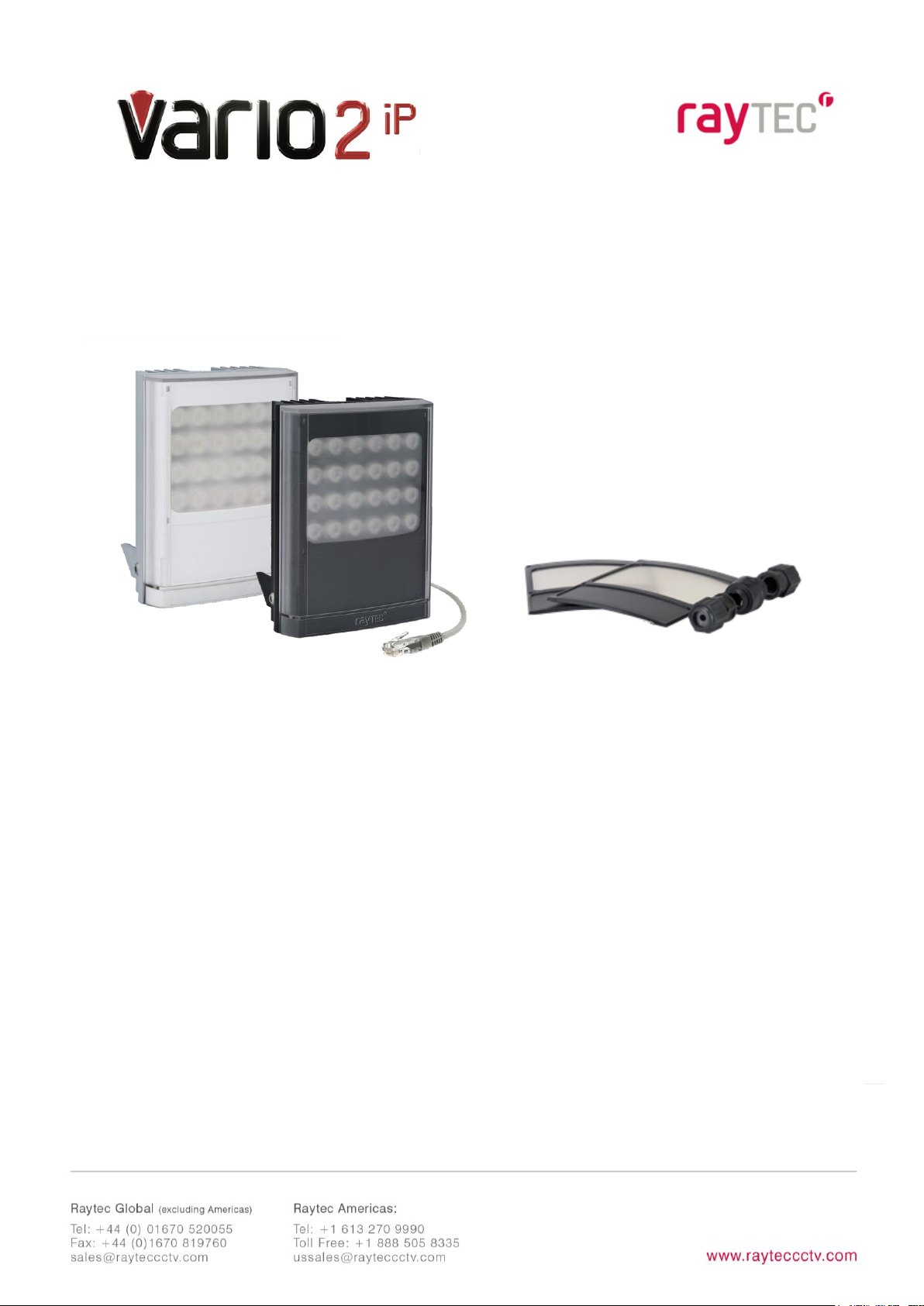
Box Contents: (Standard Specification)
VARIO2 16 IP Illuminator - Infra-Red (IR) or White-Light (WL)
containing 35° x 10° beam angle ILS (Inter-changeable Lens System)
60° x 25° beam angle ILS
Waterproof RJ45 connector
Accessories (optional):
80° x 30° beam angle IHD
120° x 50° beam angle IHD
System requirements: PC running Windows 7 with IE9 (or equivalent) and network
access.
Version : Vario2 IP
16 Instruction Guide Rev 1.0.0
Full
Page 2

2
• Install in a well ventilated area
• Do not stare at the illuminator for prolonged periods
• IR Variants: CAUTION - IR emitted from this product – Risk Group 2.
Avoid prolonged exposure or use appropriate shielding or eye protection. Risk
Group 2 for cornea / lens infrared hazard. At a distance of more than 1840mm
for all products the unit is in the exempt group.
• White Light Variants: Risk Group 2 Classification. Caution – Possible
hazardous optical radiation emitted from this product. May be harmful to
eyes, do not stare at the illuminator. Hazard distance is 1840mm.
Product Introduction
VARIO2 IP is a Network Illuminator designed to connect to a suitable network and is
provided with an integrated Web Interface. The Raytec Discovery Tool allows for easy
identification and connection to the illuminator or you can connect directly to the
illuminator via its IP address.
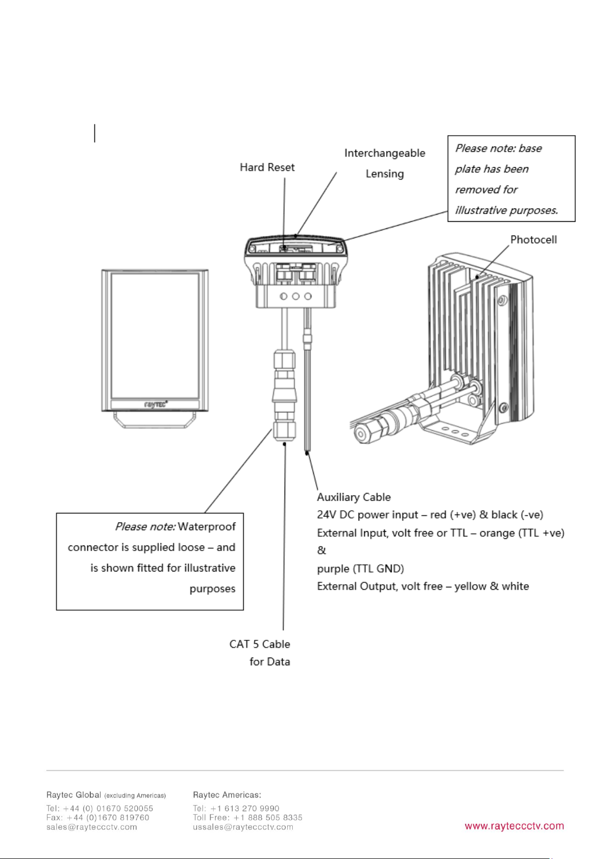
The illuminator has a CAT 5 cable for data connection, can be powered and is
supplied with a waterproof CAT 5 connector.
The illuminator has a photocell for automatic day/night switching and has an External
Input (to act as a telemetry, trigger input, volt free or TTL) and an External Output
(volt free output). It also benefits from Raytecs interchangeable lens system so that
the correct angle of illumination can always be achieved easily.
The illuminator has Operator and Administrator log-in and access rights. The
Operator has access to the Homepage and Diagnostic pages. The Administrator has
access to all pages.
An API is available for programmers for integration
within a VMS / BMS environment. The illuminator also
Page 3

3
has a HTTP API to control the illuminator via HTTP
commands.
Page 4
4
Page 5

5
Basic Steps
(Quick Installation Guide P1-21/ Detailed Guide P22)
STEP 1: Safety Information (Pg. 2)
STEP 2: Wiring (Pg. 6)
Apply 24V DC to red and black cores of auxiliary cable and use standard CAT 5 or
better for data connection. Connect external inputs and external output wires as
required.
IMPORTANT:
Ensure 24V PSU are suitably rated
Ensure Cat 5 cable and auxiliary cable are correctly terminated and waterproofed after
installation
STEP 3: Lens Selection and Physical Installation (Pg. 7)
Adjust interchangeable lens if required.
Fix to wall, pole or camera unit using U bracket provided or other Raytec bracketry.
IMPORTANT:
Ensure illuminator is rated to provide required viewing distances and select correct angle
Ensure illuminator is orientated in the correct direction
Page 6

6
STEP 4: Change IP address and connect to the illuminator (Pg. 9)
All VARIO2 IP have the same default IP address and this must be changed
immediately to avoid any potential conflicts or communication errors.
We recommend the easiest and fastest way to identify and connect to illuminators is
using the Raytec Discovery Tool where the IP address can be altered or DHCP
enabled.
Alternatively, type the IP address of illuminator into a web browser – default is
192.168.2.80 – and use the web interface to manually alter IP address.
IMPORTANT:
We recommend Raytec Discovery Tool as the easiest way to establish communication. If
using IP address for direct communication, illuminator and computer must be in same
network range.
STEP 5: Illuminator Set-Up (Pg. 12)
Raytec Discovery Tool Basics
Log-in, Security & Basic Illuminator Setup
Basic Web Page Functionality
STEP 6: Basic Troubleshoot (Pg. 19)
Full, detailed instructions begin on page 21
Page 7
7
Wiring
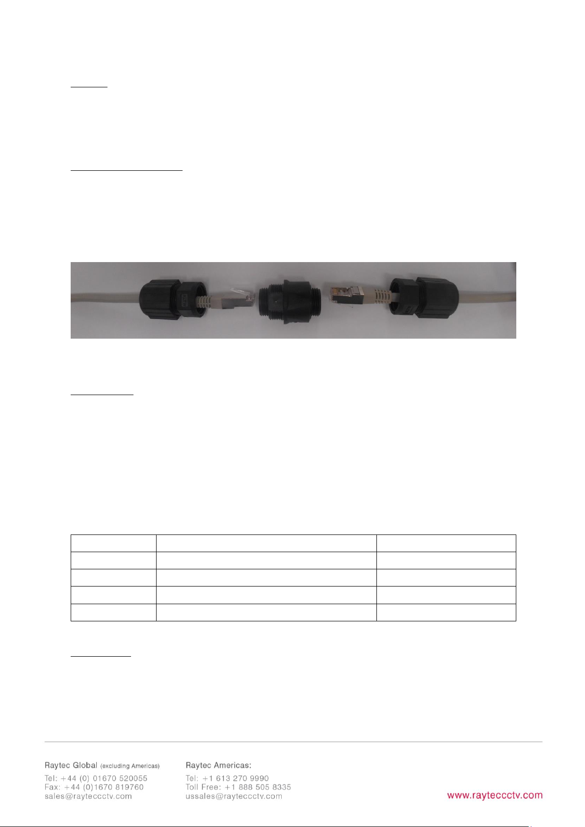
The illuminator is supplied with a terminated CAT 5 cable with a waterproof Ethernet
connector (supplied loose i.e. not fitted) and an auxiliary multi-core cable.
Network Connections
Ensure you make a waterproof connection to the RJ45 as shown below. Ensure the
connector is waterproof and sealed after the connection is made.
To illuminator RJ45-RJ45 connector To Network
24V DC PSU
Connect 24V DC to the red (+ve) and black (-ve) cables of the auxiliary cable.
Ethernet cable is a data connection only.
Connect external input trigger and external output as required – see table below:
Colour
Description
Wire Gauge (AWG)
Orange
External Input -Volt free or TTL +ve
22
Purple
External Input -Volt free or TTL GND
22
Yellow
External Output – Volt free
22
White
External Output - Volt free
22
WARNING: To maintain the IP rating of the product the multi-core auxiliary cable
must be waterproofed and terminated appropriately even if it is not in use.
Page 8
8
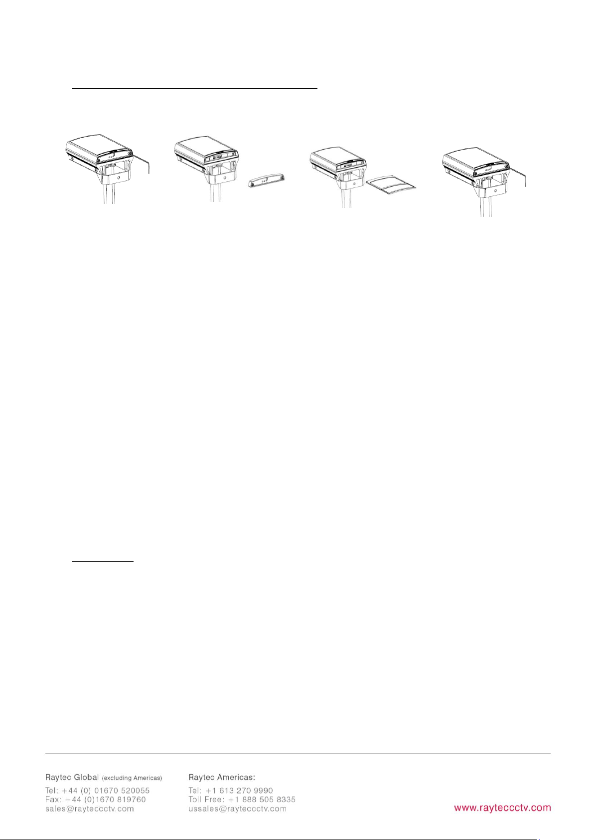
Interchangeable Lenses: Changing the Angle
The illuminator is delivered with a 35o beam angle. To alter to 10o, remove the
baseplate from the bottom of the product and remove the existing lens and then reattach the baseplate securely. With no lens insert the product produces a 10o beam
angle.
To alter to any other angle, remove the existing lens and insert the required lens
which will have its angle indicated on it. Ensure the baseplate is securely re-attached
to maintain waterproof integrity of the product.
The angles available as standard are: 10°x10° (NO lens / diffuser in place), 35°x10°
and 60°x25°. Other angles are available to order: 80°x30° and 120°x50°.
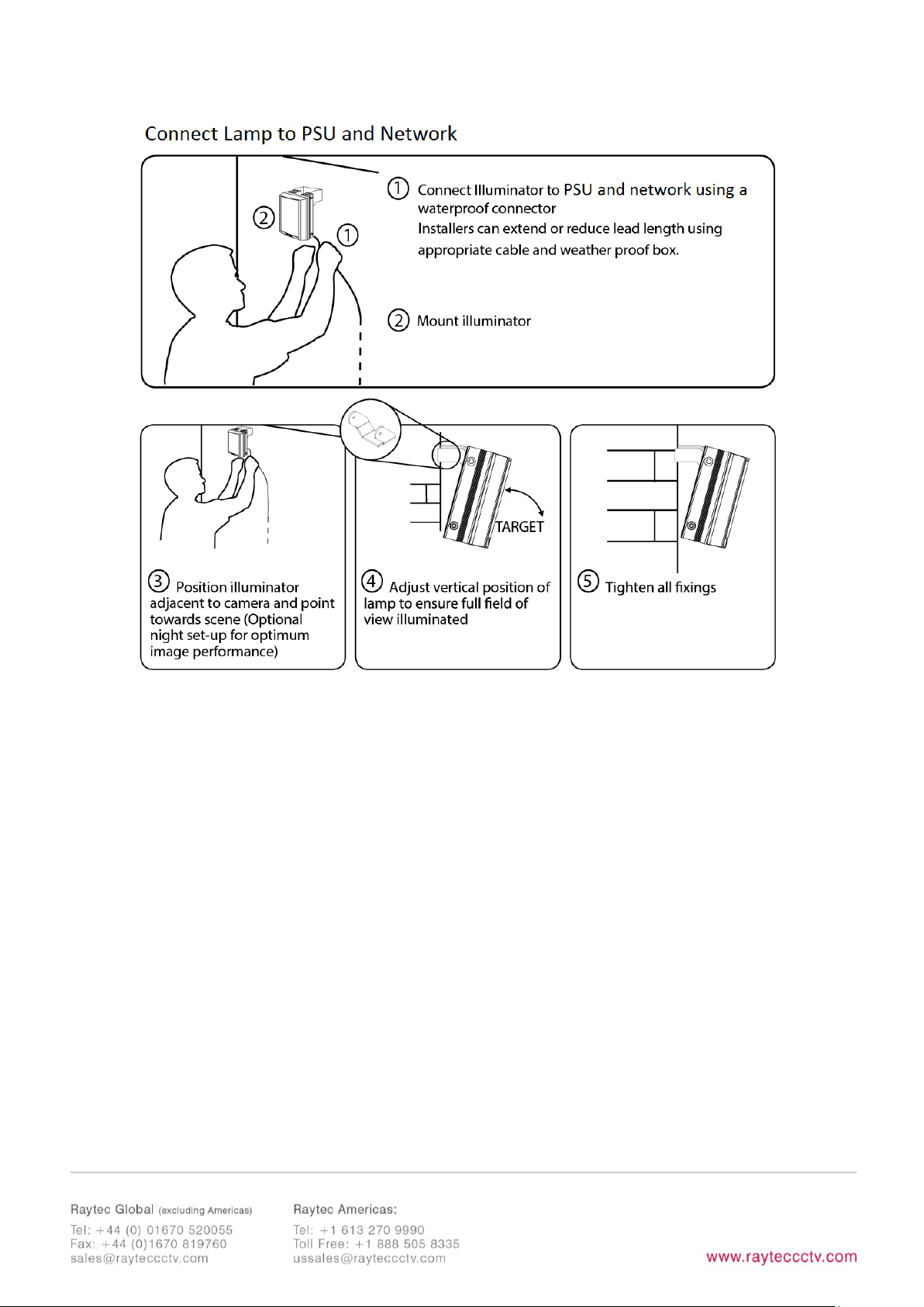
Installation
VARIO2 IP is delivered as standard with a bracket at the bottom of the unit. This
can be moved to the top of the unit if required.
Attach illuminator to wall, housing or pole using U-bracket provided or dedicated
Raytec bracketry.
Step 1
Unscrew baseplate
Step 2
Remove baseplate
Step 3
Remove / Replace
diffuser lens
Step 4
Replace baseplate
& tighten
Page 9
9
Notes :
To maintain the IP rating of the product, any cable not in use must be waterproofed
and terminated appropriately.
Page 10

10
Connecting to the Network
Assign an IP Address
All VARIO2 IP have the same default IP address (192.168.2.80) and this must be
changed immediately to avoid any potential conflicts or communication errors.
There are two main ways to change the IP address of an illuminator:
OPTION 1: Raytec Discovery Tool
We recommend the easiest and fastest way to identify and connect to illuminators is
using the Raytec Discovery Tool where the IP address can be altered or DHCP
enabled. Using the Raytec Discovery Tool avoids the need to have the computer and
illuminator in the same network range in order to alter the IP address. This free
application is downloadable from our website or please contact Raytec.
To change the IP address using the Raytec Discovery Tool so that you can
communicate with the illuminator(s) you can:
Use DHCP
Run the Raytec Discovery Tool. Single click on illuminator to highlight it. Select
Network
from bottom menu. Highlight DHCP option. Press
OK,
then
OK
again to
the “Confirm Changes” dialog box. Press
Discover
. The illuminator should now
appear with a valid IP address. You can now double click illuminator to navigate to it.
WARNING: Your network must have DHCP capability.
Manually set the IP address
Run Raytec Discovery Tool. Single click on illuminator to highlight it. Select
Network
from bottom menu. Type in a new IP address and subnet mask - which must be
Page 11

11
compatible with your network. Check with your IT manager. After changing the IP
address and subnet mask, press
OK,
then
OK
again to the “Confirm Changes”
dialog box. Press
Discover
. You can now double click illuminator to navigate to it.
OPTION 2: Use the Illuminators Web Interface
Alternatively, type the IP address of illuminator into a web browser – default is
192.168.2.80 – and use the web interface using the “Network” tab on the left hand
side to manually alter the IP address or enable DHCP. For manual allocation of a
static IP address it is important that the network administrator controls and ensures
the IP addresses issued are unique and not repeated. In order to establish
communication the computer and illuminator must be in the same network range.
In either option above, if DHCP is enabled, your network must have DHCP capability.
Note: - If assigning the IP address fails, check that there is no firewall blocking the
operation and that the computer and illuminator have IP addresses in the same
range.
Raytec Discovery Tool Basics
The Raytec Discovery Tool is downloadable from our website or you may request it
from Raytec.
During the initial set-up we strongly recommend that you use the Raytec Discovery
Tool on a computer on the same network as the VARIO2IPilluminators to discover
and establish connection.
The illuminator responds to multicast messages - and therefore does not need to
have a valid IP address in the same network range for the Raytec Discovery Tool to
find it. But it does require a valid IP address for connection and communication. ALL
IP addresses need to reside within the same network address range to ensure these
Page 12

12
components can communicate with each other.
With the VARIO2 IP powered and attached to the same network, press
Discover
and
the Raytec Discovery Tool will display a list of illuminators available on the network.
See instructions above on how to change IP address or enable DHCP in order to
allow communication with the illuminator.
Once the IP address of the illuminators have been changed, you can double click on
the illuminator from the Raytec Discovery Tool to navigate directly to the illuminators
web interface.
The Raytec Discovery Tool allows you to:-
• Discover all illuminators on the network – illuminators do not need a valid IP
address to be discovered
• Alter IP address of illuminator – the illuminator must have a valid IP address to
allow communication
• Enable DHCP
• Navigate directly to each illuminator – once a valid IP address has been
assigned
• See the illuminators status
• See whether the illuminator is ON / OFF
• View the MAC address of each illuminator
• Change Network Settings
• Change the Name and Group Name
• See additional illuminator details including name, firmware version, model and
the time the illuminator has been powered.
Page 13

13
Hierarchy of Photocell vs. Telemetry
• If the telemetry function is enabled, then the photocell must detect that it is
dark for the telemetry function to operate.
• The photocell overrides the telemetry function during the day. If the external
input/telemetry function needs to be operated 24 / 7, then the photocell
function should be disabled from the settings / groups page.
• If the external input/telemetry is not active, then the unit will follow the
photocell settings.
The system requires 15 seconds of light to deactivate the photocell and turn the
illuminators off to avoid accidental turn off of the illuminators via car headlights or
torches.
If illuminators are in groups, the following rules apply:
- ANY sending illuminator within a group which says it is dark will turn all the
illuminators in the group on (subject to local illuminator settings)
- ALL illuminators in the group need to say it is light before all the group
illuminators will go off together (subject to local conditions)
Log-in, Security & Basic Illuminator Setup
Log-in using Operator or Administrator user names and passwords. Operator has
limited access rights. Administrator has full access rights.
Defaults (User Names & Passwords are case sensitive):
Users & Passwords
Name
Password
Operator
user
password
Administrator
admin
password
In order to maintain maximum security of your system, we recommend you change
the passwords at the earliest opportunity (for further information, please see page 49
of full installation instructions).
Page 14

14
Take instant control of a illuminator by pressing the Override button on the home
page. This will countdown for 30 minutes to allow the user to control the illuminator
and then will revert to standard settings automatically or if the Override button is
deselected. Override is only available when the illuminator mode is set to
Local,
HTTP + Local
or
VMS + Local
.
To operate the illuminator via a VMS or third party application that uses the Raytec
API, then the illuminator mode should be set to
VMS
or
VMS + Local.
In VMS mode
the illuminator will ignore Photocell and External Input triggers and respond only to
valid VMS commands. In
VMS + Local
mode the illuminators can be controlled via a
VMS system whilst also still responding to local photocell and telemetry triggers.
To operate the illuminator with an application that uses the HTTP API, then the
illuminator mode should be set to
HTTP
or
HTTP + Local.
In HTTP mode the
illuminator will ignore Photocell and External Input triggers and respond only to valid
HTTP commands. In
HTTP + Local
mode the illuminators can be controlled with
HTTP commands whilst also still responding to local photocell and telemetry triggers.
VMS integration allows the illuminator(s) to be directly controlled and triggered by
events within the VMS environment such as scheduled events, alarm triggers, camera
commands, etc.
HTTP Integration allows the illuminator to be directly controlled and triggered on
receipt of valid HTTP commands generated on the network from VMS, cameras or
other components capable of generating HTTP commands.
The illuminator mode can be changed on the Settings / Groups page. The default
illuminator mode is
Local
.
Standard Setup – Factory Defaults
The illuminator is operating in Local mode and will respond only to its own photocell
and telemetry status. By default the illuminator is NOT assigned to a group.
The illuminator will turn ON / OFF automatically when the photocell detects it is dark
/ light at 100% (soft start) via the photocell.
Page 15
15
The External Input will activate the illuminator at 100% (NOT soft start) for the
duration of the input provided the photocell detects it is dark.
External Output: activated by photocell and will become short circuit when active.
Factory Defaults
Name
VARIO2 IP
Group Name
<<Deliberately Left Blank>>
IP Address
192.168.2.80
Enable DHCP Checkbox
Not Selected – IP addresses will NOT be automatically
allocated. If illuminator is being operated on a DHCP enabled
network, DHCP can be selected for automatic allocation of IP
address.
Illuminator Mode
Local:
Control the illuminator using the web interface.
Illuminator will respond to its own photocell and telemetry
events.
Photocell
External Input
Trigger Control
Illuminator Control
Illuminator Control
Respond to Group
Commands
No, ignore group
command
No, ignore group
command
Illuminator Mode on
Trigger
On
On
Power (%)
100%
100%
Duration
All night
Duration of Input
Soft Start
On
Off
Deterrent
Pattern = SOS
Frequency = Slow
Page 16

16
Advanced Settings
Manual Override
Photocell Sensitivity = 20 lux
Countdown Duration = 30 mins
External Input
Type of Input = Volt Free
Active State = Short Circuit / Low
External Output
Trigger State = Photocell Only
Active State = Short Circuit / Low
Page 17
17
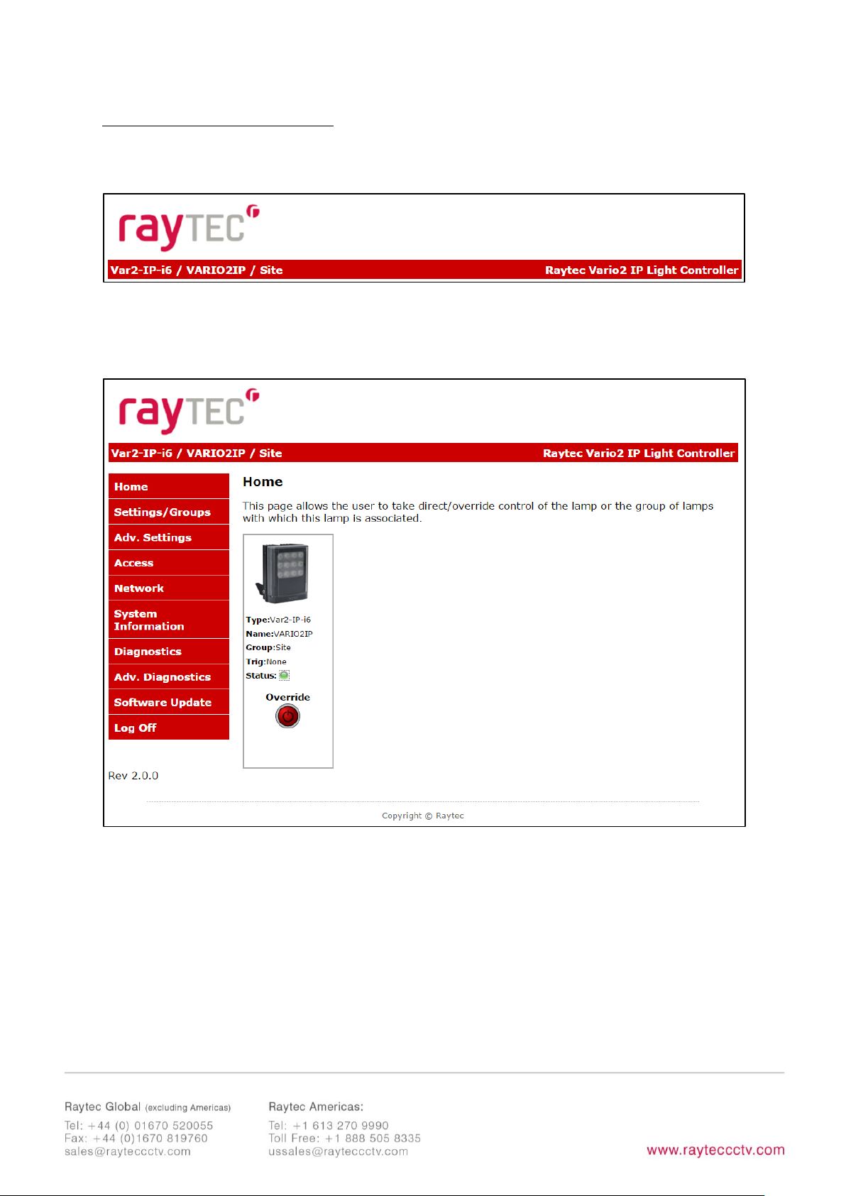
Basic Web Page Functionality
All web pages have the following information in the header bar
Model Type / Lamp Name / Group Name
User has access to Home Page and Diagnostics pages.
Admin has access to all pages.
Page 18

18
Page Name Functions available
Home Page Allows manual control of an individual illuminator or
group of illuminators including power adjustment, boost
and deterrent controls. Select override to operate above
functions.
Settings / Groups Allows detailed set-up and configuration of the
illuminator including how it responds to Photocell and
External Inputs, duration on period, power levels, soft
start, response to group commands, deterrent patterns
and speeds. Allows illuminators to be allocated to a group
or to create a new group. Selectable control of illuminator
either locally, by VMS or HTTP commands.
Adv. Settings Allows for further detailed setup of External Input,
External Output, Photocell sensitivity level and duration of
Override.
Access Change passwords
Network Allocate IP address and other network settings, select
DHCP operation, allocate illuminator name
System Information Indicates basic information about the illuminator. Ability
to restore factory settings or restart illuminator.
Diagnostics Basic diagnostics to enable 1st level troubleshooting
Adv. Diagnostics Advanced diagnostics to enable 2nd level troubleshooting
Software Update Indicates current software / firmware version. Ability to
upload updated software / firmware version.
Log Off We recommend logging off illuminator after every session
Page 19
19
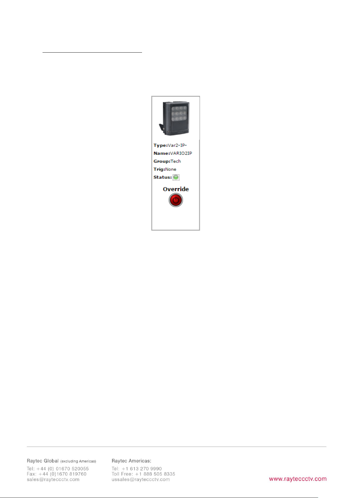
Illuminator web interface note
You may see the model name of your illuminator cut short on the home page of your
illuminator like below:
Due to a change to the format of our model names, the size of the illuminator details
box above has been increased. If you have previously used a Vario IP on your
machine, your browser will have remembered the old style and will re-use this. You
can force your browser to pull the size change in by removing temporary Internet
files, this procedure is explained for Chrome and Internet Explorer browsers below.
Chrome
Internet Explorer
1. Hold Ctrl-Shift-Del keys
2. Change drop down box to “the
beginning of time”
3. Tick “
Cached images and files”
ONLY. If others are ticked, untick.
4. Select
Clear browsing data
1. Hold Ctrl-Shift-Del keys
2. Tick
“Preserve Favourites website
data”
and
“Temporary Internet files
and website files”
ONLY. If others
are ticked, untick.
3. Select
Delete
After performing the steps above, refresh the illuminator home page and the longer
illuminator details box will appear.
Instructions for this procedure for other browsers can be found online.
Page 20

20
Ping
The illuminator will respond to a standard Ping command sent to its valid IP address.
For the ping command to work the illuminator and computer must reside in the same
network range.
Basic Troubleshoot
• Check if the camera and illuminator are aligned correctly.
• For Infra-Red illumination, ensure that a Day and Night or Black and White
camera is used and that the camera switches correctly into night mode.
• Check camera and lens. Is iris fully open at night and set correctly. Ensure
camera is fully operational and has correct night time settings and capability.
• Ensure correct illuminator lens angle selected for required distance – check
stated performance.
• Check the LED status indicator: if green LED indicator is lit on the bottom of
the unit, then the unit is receiving power.
• Check voltage applied and that power supply is suitably rated for the VARIO2
IPunit – see page 6 for required ratings.
Check connection and wiring of CAT5 / 6 cable to VARIO2 IP. Verify link has
been established with the router / switch to which the illuminator is connected
.
• If the illuminators are correctly wired to the network, run the Raytec Discovery
Tool and try to discover the illuminator on the network.
If the illuminator is discovered and the “State” indicator is grey, this
indicates that there is no communications with the illuminator. Ensure IP
Address and Subnet Mask of computer and illuminator are set within the same
range. If not, alter IP address of illuminator or Enable DHCP on illuminator for
Page 21

21
automatic allocation of suitable IP address.
Use a Ping command to see if the illuminator and device are on the same
network and have communication.
• If still unsuccessful try a different web browser.
• If unit still cannot be discovered then type default IP address into browser:
192.168.2.80
• If no communication possible after above steps, please contact Raytec for
further support or consider a Hard Reset of the illuminator.
Page 22

22
Detailed Installation Guide
Contents
Box Contents: ....................................................................................................................... 1
Accessories (optional): .......................................................................................................... 1
Safety Information and Product Introduction ......................................................................... 2
Basic Steps ........................................................................................................................... 5
Wiring ...................................................................................................................................................... 7
Interchangeable Lenses: Changing the Angle .......................................................................... 8
Installation ............................................................................................................................................. 8
Connecting to the Network ........................................................................................................... 10
Raytec Discovery Tool Basics ........................................................................................................ 11
Hierarchy of Photocell vs. Telemetry ......................................................................................... 13
Log-in, Security & Basic Illuminator Setup .............................................................................. 13
Factory Defaults ................................................................................................................................. 15
Basic Web Page Functionality ....................................................................................................... 17
Illuminator web interface note ..................................................................................................... 19
Ping ................................................................................................................................................... 1920
Basic Troubleshoot ........................................................................................................................... 20
Raytec Discovery Tool in Depth .......................................................................................... 25
Network Settings ............................................................................................................................... 26
DHCP – Automatic allocation of IP address ............................................................................ 27
Static Network Configuration – Manual allocation of IP address .................................... 28
Page 23

23
Name and Group Name ................................................................................................................. 29
lluminator Status .......................................................................................................................... 3031
Other Information ........................................................................................................................ 3031
Unit Details – Parameters .......................................................................................................... 3132
Detailed Illuminator Setup: Web Interface Pages ............................................................ 3233
Log-In Page .................................................................................................................................... 3233
Home Page ..................................................................................................................................... 3334
Settings / Groups ................................................................................................................ 37
Illuminator Mode .............................................................................................................................. 38
Groups ................................................................................................................................................... 40
Group Name .................................................................................................................................. 4041
Trigger Control .............................................................................................................................. 4041
Respond to Group Commands ............................................................................................... 4041
Lamp Mode On Trigger ............................................................................................................. 4142
Power ................................................................................................................................................ 4432
Duration ........................................................................................................................................... 4243
Soft Start ......................................................................................................................................... 4344
Deterrent Pattern & Frequency............................................................................................... 4344
Advanced Settings .............................................................................................................. 46
Manual Override - Countdown Duration ................................................................................. 46
External Input – Select type of Input & Active State on Input .......................................... 47
External Output .................................................................................................................................. 47
Page 24

24
Photocell Sensitivity ......................................................................................................................... 48
Access / Passwords ............................................................................................................ 49
Network........................................................................................................................... 5051
Enable DHCP .................................................................................................................................. 5051
Manual IP Address ....................................................................................................................... 5152
Network - IP Address Changed- Reboot ............................................................................. 5152
System Information ......................................................................................................... 5354
Restore Factory Settings ............................................................................................................ 5354
Reboot / Restart Illuminator .................................................................................................... 5455
Diagnostics ......................................................................................................................... 56
Advanced Diagnostics ......................................................................................................... 57
Software Update ................................................................................................................. 58
Log Off ................................................................................................................................ 60
Hard Reset Button – Located on illuminator .................................................................... 6061
Raytec APIs (VMS and HTTP) ................................ ........................................................ 6162
Troubleshooting & FAQs ................................................................................................. 6162
Page 25

25
Raytec Discovery Tool in Depth
The Raytec Discovery Tool can be obtained from the Raytec website. Once installed,
run the application and press
Discover
.
The Raytec Discovery Tool will discover and display all VARIO2 IP Illuminators on
your network.
The illuminator responds to multicast messages - and therefore does not need to
have a valid IP address in the same network range for the Raytec Discovery Tool to
find it. But it does require a valid IP address for connection and communication.
The Raytec Discovery Tool allows you to:-
• Discover all illuminators on the network – illuminators do not need a valid IP
address to be discovered
• Alter IP address of illuminator – it must have a valid IP address to allow
communication
• Enable DHCP
• Navigate directly to each illuminator – once a valid IP address has been
assigned
Page 26

26
• See the illuminators status
• See whether the illuminator is ON / OFF
• View the MAC address of each illuminator
• Change Network Settings
• Change the Name and Group Name
• See additional illuminator details including name, firmware version, model and
the time the illuminator has been powered.
On the image above, two illuminators have been discovered on the network. They are
unique in that they have different MAC addresses, but the same IP Address and Unit
Name. The application allows the illuminators to be configured.
Network Settings
To change the network settings, highlight the illuminator to be changed and press
Network
.
The “Network Configuration” screen will be shown.
Page 27

27
Two options are available to set the IP Address at this stage:-
1. Enable DHCP – if the network is DHCP enabled
2. Enter a Static IP Address and Subnet Mask
DHCP – Automatic allocation of IP address
Select
Obtain IP address automatically (use DHCP)
and press OK.
The unit will now be allocated an IP Address via the networks DHCP server. Refresh
the Raytec Discovery Tool by pressing
Discover
. The illuminators IP address should
automatically be updated into the required range and the illuminator can now be
accessed directly from the Raytec Discovery Tool by double clicking on the
illuminator from the list of discovered illuminators.
Page 28

28
Static Network Configuration – Manual allocation of IP address
To use static network configuration it is important that the network administrator
controls and ensures the IP Addresses issued are unique and not repeated. Enter the
appropriate IP Address and Subnet Mask having selected
Use the following IP
address
and press OK.
The unit will now be allocated the IP Address as entered. Refresh the Raytec
Discovery Tool by pressing
Discover
.
Page 29

29
Name and Group Name
All illuminators have the default name of “VARIO2IP”. This should be changed so
that the illuminator can be easily identified.
The group name is left blank by default. The group name is used to associate / group
illuminators together and allows them to interact using group commands.
Both “Name” and “Group Name” can be modified directly from the Raytec
Discovery Tool or via the web interface.
To change these via the Raytec Discovery Tool, highlight the illuminator you want to
change. Then press
Status
.
Page 30

30
“Unit Name” and “Group Name”can both be edited by entering a new value in
their fields.
Page 31

31
After the change has been made save the edited names by pressing OK.
The selected unit name and group have now been changed. Refresh the Raytec
Discovery Tool by pressing
Discover
and the updated information should be
displayed.
lluminator Status
The Raytec Discovery Tool has two status indicators for each illuminator. The colours
of these indicators change depending on the state of the illuminators as described
below:-
Red
Green
Grey
State
Illuminator Fault
Illuminator OK
No communication
On / Off
N/A
Illuminator On
Illuminator Off
An illuminator fault is indicated if:-
1. An LED fault exists within the illuminator.
2. The input voltage is outside specified limits.
Other Information
The Raytec Discovery Tool does not automatically refresh, therefore to view any
Page 32

32
changes it is important that the page is refreshed by pressing
Discover
.
When changes are made to an illuminator or a new illuminator is added there may be
a small delay in making contact or updating the information and so
Discover
may
need to be pressed more than once.
Unit Details – Parameters
Selecting the Parameters button within the “Unit Details” screen provides a high
level of detailed information regarding the performance and operation of the
illuminator. This is designed to be used during technical support of the illuminator
with Raytec or your supplier.
Page 33

33
Detailed Illuminator Setup: Web Interface Pages
Log-In Page
Access Log-In Page for individual illuminator by double-clicking on the illuminator
from the Raytec Discovery Tool or by typing the IP address into the web browser.
User Names & Passwords are case sensitive. (Max 32 characters – alphanumeric,
symbols allowed)
Log on using either Operator User Name and Password or Administrator User Name
and Password.
The Operator only has access to Home Page and Diagnostic Pages only.
Administrator has access to all pages.
The Administrator can change passwords by using the “Access” Page.
Ensure you keep a note of passwords used in a secure place.
Page 34

34
User
User name
Password
Operator
user
password
Administrator
admin
password
Forgotten Password
If you are an operator, please request the assistance of the administrator. They can
reset the password through the “Access” Web Page.
If you are an administrator, you will have to use the Hard Reset button on the
illuminator – refer to Access / Passwords section on page 49. This will restore the
illuminator to factory defaults which includes user names and passwords.
Home Page
After a successful log-in, the Home Page / Manual Override Page will be displayed.
You can navigate to all pages using the side navigator bar which is available on all
pages.
Page 35

35
The Home Page / Manual Override Page displays the current status of the
illuminators including the following information:
- A visual representation of the product and its current state (ON or OFF)
- Product Type & Model
- Product Name - if a name has been assigned (using Network Page or Raytec
Discovery Tool)
- Group Name - if a name has been assigned (using Settings / Group Page or
Raytec Discovery Tool)
- Trig – if illuminator is on, this will indicate the type of input trigger
- Status – LED indicator will indicate if the illuminator is healthy (green LED) or if
there is potentially an issue with the illuminator (amber LED)
Home Page / Manual Override
All users can access Manual Override features shown below by selecting the
Override
button.
When selected, additional features will appear and Manual Override countdown will
commence. Factory default Manual Override countdown is 30 minutes. This setting
can be adjusted by the administrator on the“Adv. Settings” Page. The countdown
duration can be reset at any time and will restart from maximum time. The Manual
Override function can be deselected at any time and the illuminator will return to
normal operating mode.
On & Group On
The current ON / OFF status will be displayed by the red / green button together with
the current power level of the illuminator. Use the slider bar to change the power
level.
To turn all illuminators ON in the same group and control power level – select the
Group ON
button.
All illuminators in a group will turn on to the power setting selected.
When
ON
or
GROUP ON
button is turned OFF, illuminators will return to their
normal operating mode.
Page 36

36
Important - If an illuminator is in group override control from another illuminator you
will not be able to access the override control on that illuminator.
Boost & Group Boost
This will boost the individual illuminator or all illuminators in the group (if GROUP
BOOST selected) to 110% of normal output power for a period of 10 seconds. Boost
will then be disabled for 100 seconds whilst the illuminator recharges.
Deterrent & Group Deterrent
This will turn the individual illuminator or all illuminators in the group (if GROUP
DETERRENT selected) into deterrent mode. The current pattern and frequency of the
deterrent is displayed and can be changed on settings / groups page. Power setting
of illuminator(s) in deterrent mode can also be adjusted by using slider bar.
Page 37

37
Settings / Groups
This page is used to configure the operation of the illuminator based on Photocell
and / or External Inputs, configure the illuminator to operate in Local, VMS or HTTP
mode, assign the illuminator to a Group and configure the deterrent mode of the
illuminator.
The illuminator can be configured to operate from the above inputs independently
and the power level, duration and soft start function can be configured.
Page 38

38
WARNING: For changes to take effect, the
SAVE
button must be pressed
WARNING: You cannot see the effect of your changes if the
Override
button on
the Home Page is still active (green) or your illuminator is in group Override
control from another illuminator
Illuminator Mode
The illuminator can be operated in five different modes:
1. Local
2. VMS
3. VMS + Local
4. HTTP
5. HTTP + Local
These modes are selected in the illuminator mode selection box.
Page 39

39
1. Local
The illuminator will respond ONLY to photocell and telemetry events. The user may
also take direct Manual Override control through the Home Page interface. This is the
default setting.
2. VMS
The illuminator will respond ONLY to third party VMS systems and any applications
that use the Raytec API. The illuminator will NOT respond to photocell and telemetry
events. The user CANNOT take direct manual override control through the web
interface.
3. VMS + Local
The illuminator will respond to third party VMS systems and any applications that use
the Raytec API and the illuminator will ALSO respond to photocell and telemetry
events. The user may ALSO take direct Manual Override control through the home
page of the illuminators web interface.
IMPORTANT:
For detailed instructions on“VMS”and“VMS + Local”modes please refer to the Raytec
API Document.
4. HTTP
The illuminator will respond ONLY to any device / application generating valid HTTP
commands and any applications that use the Raytec HTTP API. The illuminator will
NOT respond to photocell and telemetry events. The user CANNOT take direct
Manual Override control through the web interface.
5. HTTP + Local.
The illuminator will respond to any device / application generating valid HTTP
commands and any applications that use the Raytec HTTP API and the illuminator will
ALSO respond directly to photocell and telemetry events. The user may ALSO take
Page 40

40
direct Manual Override control through the web interface.
IMPORTANT:
For detailed instructions on "HTTP”and“HTTP + Local”modes please refer to the
Raytec HTTP API Document.
VMS Options – Additional Information :
There is a RaytecAPIInstaller.exe and a Raytec API Quick Start guide available to
support VMS integration.
HTTP Options – Additional Information :
There is a Raytec HTTP Command Summary guide and a Raytec HTTP API guide
available to support HTTP integration.
Groups
The VARIO2 IP illuminator is configured so that it can work individually or as part of a
group of illuminators. This group control gives the user more flexibility and capability
in terms of how they want their illuminators to operate.
Illuminators can respond to Group commands in three ways and each illuminator can
be configured individually to respond to Photocell or External Input triggers:
•
Ignore group commands
– the illuminator will ignore all group
commands
•
Yes, Send and Receive
– the illuminator can both originate a group
command and will respond to group commands
•
Yes, Receive only
– the illuminator will only respond to group
commands
The maximum possible number of illuminators in a group is 16.
Some examples of illuminator functionality in a group:
• All illuminators to come ON at the same time and go OFF at the same time
Page 41

41
• One illuminators External Input trigger can turn all illuminators in the group
ON (E.g. Car park entrance / Alarm)
• The Group Override function on the Home Page allows the user to take instant
control of the group of illuminators all at the same time
Group Name
An illuminator can be associated with a new or existing group to enable it to follow
group commands from the photocell input and / or External Input. A new group
name can be created by typing into the “Enter Group Name” box. Ensure that
duplicate names are avoided. Or the illuminator can be allocated to an existing group
by selecting an existing group from the drop down list of groups.
Trigger Control
For both Photocell and External Input, the user can select 3 action states:
1. Inactive
The illuminator ignores the input
2. Lamp Control
The illuminator will respond to its own input
3. Group Control
The illuminator will respond to an input from illuminators within its
group – based on selection from Respond to Group Commands below
Factory Defaults: Photocell Lamp Control
External Input Lamp Control
Respond to Group Commands
Page 42

42
If Group control is NOT selected from Trigger Control options, then the illuminator
will not respond to any Group commands.
If Group Control is selected from Trigger Control options, then the user can select
two modes of operation in response to Group Commands:
1. Yes, Send & Receive
The illuminator will both originate group commands based
on the trigger AND respond to group commands from
other illuminators in its group.
2. Yes, Receive only
The illuminator will only respond to group commands
from other illuminators in its group but it will NOT
originate any group commands.
Factory Defaults: Photocell No, ignore group commands
External Input No, ignore group commands
Some examples of illuminator functionality in a group:
• All illuminators can come on at the same time and go off at the same time by
either Photocell or Ext input control from a single illuminator
• The Group Override function on the Home Page allows the user to take instant
control of the group of illuminators all at the same time
Lamp Mode On Trigger
This dictates the status of the illuminator on receipt of a valid instruction from
Photocell and/or External Input. For both the Photocell and the External Input, the
illuminator can either be programmed to stay off or to turn on.
In addition, the External Input can activate the Deter mode – which can be configured
below.
Page 43

43
Factory Defaults: Photocell On
External Input On
Power
This dictates the power level that the illuminator turns on at in response to a valid
instruction. Power levels can be set from 20% to 100% using the slider bar.
Factory Defaults: Photocell 100%
External Input 100%
Duration
This will dictate how long the illuminator will stay on (if ON command is selected) on
receipt of a valid instruction.
For the Photocell input the user can select
All Night
in which case the illuminator will
stay ON (if ON command is selected) for the whole period of time that the photocell
indicates it is dark. Alternatively, a specific time period can be selected using the
slider bar.
The timer will only operate whilst the photocell indicates it is dark. If the photocell
indicates it is light before the timer has elapsed then the timer is ignored and the
light turns OFF.
For the External Input, the user can select
For Duration of Input
in which case the
illuminator will stay ON or deter (if ON or deter command is selected) for the whole
period of the duration of the input.
Alternatively, a specific time period can be selected using the slider bar. The
illuminators will operate immediately and the timer duration starts from the end of
the External Input signal. The External Input can be reactivated within the timer
Page 44

44
period and it will have the effect of restarting the timer.
The illuminator will stay ON until the end of the timed period even if the illuminators
photocell states it is daylight.
Min and Max timer settings are:
Photocell Min: 30 mins External Input Min: 1 mins
Photocell Max: 720 mins External Input Max: 60 mins
Factory Defaults: Photocell All Night
External Input Duration of Input
Soft Start
There is the option, when a valid on instruction is received, for the illuminator to
either start immediately (
Soft Start Off)
or to ramp up to selected power level
(Soft
Start On)
.
The length of time of the ramp up depends on power level selected. (Max 10 seconds
for 100% power)
Factory Defaults: Photocell On
External Input Off
Deterrent Pattern & Frequency
There are 3 selectable deterrent patterns available if Deter Feature selected from
Illuminator Mode on Trigger:
Page 45

45
Traditional SOS pattern
3 short on/off, 3 longer on/off, 3 short on/off
Wave
The illuminator slowly ramps up and down from 100% to 20%
Hi-Lo
The illuminator alternates between 100% and 20% power
Factory Default: SOS
There are 3 selectable deterrent speeds available; Slow, Medium, Fast
Factory Default: Slow
Page 46

46
Advanced Settings
This page is used to further configure the operation of the illuminator based on more
detailed requirements of the Photocell, External Input, External Output and to set the
duration of the Override Timer.
Manual Override - Countdown Duration
There are 8 selectable durations from a drop down list for the Countdown Duration
of the Manual Override feature on the Home Page. This determines the amount of
time that the user can manually override the illuminator or group of illuminators.
Page 47

47
Factory Default: 30 minutes
External Input – Select type of Input & Active State on Input
The External Input wires will accept either volt free or TTL inputs – see polarity on
wiring instructions on page 6. The correct type of input must be selected from the
drop down list to match the input to ensure correct operation.
The Active State lets the user define the External Input State, either Short or Open
Circuit. For example: configuring the setting to Short Circuit will activate the
illuminator when the Input is closed, short circuit.
Factory Default: Volt free
Factory Default: Short Circuit/Low
External Output
The External Output is a volt free open / short output.
Page 48

48
External Output Trigger State: The drop down box gives you the option to disable the
external output signal or make the signal dependant on active states of either the
photocell or External Input or a combination of the two. (Photocell Active State =
Darkness. External Input Active State = Valid Trigger received. )
The External Output active state, provided above conditions are met, can be selected
to be open / high or closed / low.
Note: External Output is triggered by the local illuminator Photocell and the local
illuminator External Input only.
Factory Default: Photocell Only
Factory Default: Short Circuit / Low
Photocell Sensitivity
The photocell switch-on level can be altered using the slider bar.
Levels are:
Minimum level = 5 lux
Maximum level = 65 lux
Factory Default: 20 lux
There is a high level of hysteresis and an in-built delay incorporated to avoid
switching ON / OFF in marginal lighting conditions.
WARNING: For changes to take effect, the
SAVE
button must be pressed
Page 49

49
Access / Passwords
Caution:
All passwords are case sensitive.
Keep a note of all passwords in a safe place.
Defaults:
User
User name
Password
Administrator
admin
password
Operator
user
password
Only the Administrator can change passwords.
Page 50

50
Maximum number of characters:
User Name 32 characters – alphanumeric and symbols allowed
Passwords 32 characters – alphanumeric and symbols allowed
WARNING: For changes to take effect, the
SAVE
button must be pressed
Recovery of Lost Passwords
If you are an Operator, please request the assistance of the Administrator. They can
reset the password through the “Access” web page.
If you are an Administrator, you will have to use the Hard Reset button on the
illuminator – refer to Hard Reset instructions on page 61. This will restore the
illuminator to factory defaults which includes user names and passwords.
Page 51

51
Network
This page allows the configuration of the illuminators network settings.
The MAC Address is a unique identifier and cannot be changed
The Illuminator Name can be changed on this page. Avoid duplicates. Maximum
number of characters is 15 – alphanumeric.
Enable DHCP
You may enable DHCP if your network is compatible and then IP addresses will be
allocated automatically without creating duplicates.
Page 52

52
Manual IP Address
Alternatively, manually change the IP address into a suitable range for your network
by unchecking the
“Enable DHCP”
box. It is vital to avoid duplicate IP addresses.
Gateway, Subnet Mask, Primary DNS and Secondary DNS can all be changed on this
page if
“Enable DHCP”
is NOT selected.
WARNING: Please check with your IT Manager to ensure changes are compatible
with your network and the VARIO2 IP illuminator. We suggest that these settings
should only be changed by experienced users.
WARNING: For changes to take effect, the
SAVE
button must be pressed
Network - IP Address Changed- Reboot
After a network change the system will reboot to ensure that all changes have been
applied. The Reboot Screen is shown to instruct the user on how to access the
illuminator after the new network settings have been applied.
Page 53

53
Warning: We strongly recommend that IP addresses are changed via the Raytec
Discovery Tool. This is the safest way to ensure that the connection to the illuminator
is not lost as a result of setting an invalid IP address.
All other settings remain unchanged.
Page 54

54
System Information
This page shows basic information about the illuminator including software version,
product type, illuminator name and group name. This is for information only and
cannot be altered on this page.
Restore Factory Settings
At any stage, it is possible to restore ALL the original factory settings of the
illuminator. Any settings that have been previously changed will be lost. During the
“Restore Factory Settings” the illuminator may come on / flash for a short period.
WARNING: Please be aware that this will restore the default IP address of the
illuminator, 192.168.2.80, which will likely be out of the normal range of IP addresses
on your network. See Pages 10 onwards on how to set the IP address of your
illuminator.
Page 55

55
Reboot / Restart Illuminator
It is also possible to reboot / restart the illuminator. The illuminator will restart using
the existing settings of the illuminator.
A reboot / restart is generally recommended if a system becomes unresponsive or
you want to ensure settings have been reloaded correctly.
During the reboot / restart process the illuminator may come on / flash for a short
period.
Page 56

56
Diagnostics
This page is useful for first level troubleshooting and displays basic diagnostics and
information of the illuminator as follows:
Input Voltage Status
Green LED – Input voltage correctly within specified range
Amber LED – Potential fault
Check Adv Diagnostics for more information
LED Status
Green LED – All LED strings of illuminator operating correctly
Amber LED – Potential fault
Grey LED – LED status is unknown e.g. LEDs not currently on.
Check Adv Diagnostics for more information
Photocell Status
Indicates if photocell status is day or night
Ext Input Status
Indicates if external input is being received (active) or not
(inactive)
Auxiliary Output Status
Indicates if external output is active (closed) or not (open)
Page 57

57
Deterrent Pattern
Indicates which deterrent pattern is selected
Duration – Lamp On
Indicates the amount of time the illuminator has been on
Duration – Power connected
Indicates the amount of time the illuminator has been
connected to a power source.
Note: Information on this page is NOT constantly updated or refreshed automatically.
To refresh the page, press Function Key F5 or select the page again from the
navigation bars on the left.
Advanced Diagnostics
This page is useful for detailed troubleshooting and displays diagnostics and
information about the illuminator. It is intended to be used for detailed
troubleshooting with Raytec.
Note: Information on this page is NOT constantly updated or refreshed automatically.
To refresh the page, press Function Key F5 or select the page again from the
navigation bars on the left.
Page 58

58
Software Update
This page indicates the current version of the software / firmware and also enables
the software / firmware to be updated over the network.
To upload a new version of software / firmware, please contact Raytec to receive the
latest version.
Upload new version onto a computer on the network,
Choose File
, select file to
upload – then press
Install New Software
.
We would recommend that the software/firmware update is undertaken when
network traffic is low.
Page 59

59
The update will restart the unit. From software / firmware version 2.0.0 and above,
the following settings will remain unchanged:
• IP Address (if configured statically)
• DHCP mode
• Gateway address
• Subnet mask
• Primary DNS
• Secondary DNS
• Illuminator name
• Group name
• Operator user name and password
• Admin user name and password
All other settings will revert to the Factory Defaults of the new software / firmware
version uploaded.
Page 60

60
Log Off
We recommend after using the illuminator web interface that users log off using the
Log Off Page.
Page 61

61
Hard Reset Button – Located on illuminator
A hardware reset button feature has been provided that will restore ALL factory
default settings including IP address, user names and passwords etc. and can be
used in cases where communication is lost and the illuminator does not respond.
WARNING: We recommend attempting to reconnect with the
illuminator by firstly restarting the illuminator or restoring
factory settings via the integrated web interface. The hard reset
button on the illuminator should be used only as a last resort.
To reset all parameters and the IP address to Factory Default settings:
1. Disconnect power from the illuminator.
2. Remove the baseplate on the illuminator to access the reset button.
3. Press and hold the Reset button and reconnect power.
4. Keep the Reset button pressed for approximately 5 seconds until the
illuminator flashes. Release the Reset button.
5. Replace the baseplate securely to ensure unit remains waterproof.
The illuminator can now be discovered using the Raytec Discovery Tool and can be
configured as normal following the instructions in this manual. Be aware that the IP
address will have been restored to factory default, 192.168.2.80.
Hard Reset Button
Page 62

62
Raytec APIs (VMS and HTTP)
The Raytec Network Illuminator has been designed such that it can be integrated into
3rd party systems such as a VMS, BMS etc. as well as receiving HTTP commands and
Raytec have suitable APIs to support such integrations. Please contact Raytec to
discuss your particular requirements.
For full documentation to support API implementation, please contact Raytec.
Troubleshooting & FAQs
Typical Questions:
Please see Basic Troubleshooting on pages 20-21
Also, please feel free to contact us directly on the contact numbers below.
I have forgotten my Password.
– If you are an operator, contact your administrator. If
you are an administrator, then you may need to perform a hard reset of the
illuminator – see previous page.
I cannot discover my illuminator on the network using the Raytec Discovery Tool.
–
Check that there is power to the illuminator, check that the correct CAT 5 / 6 wiring is
being used, check that your computers Firewall is allowing the illuminator access and
is not blocking UDP traffic.
I cannot communicate with my illuminator from the Raytec Discovery Tool
– Make
sure the IP address of the computer and the illuminator are set to the same range to
allow communication. The default IP address of the illuminator is 192.168.2.80.
My illuminator turns on too early or too late
– First adjust the Photocell Sensitivity on
the Adv. Settings web page. Make sure the illuminator is not mounted under or next
to another another light source which may affect the performance of the photocell.
I want my illuminator to turn ON via the photocell
– Photocell operation is activated
as a factory default setting and will turn the illuminator on/off automatically provided
Page 63

63
the illuminator is in “Local”,“VMS + Local” or “HTTP + Local” mode. See page
38 for more information.
My illuminator does not trigger from an external input
– In standard mode, the
photocell must detect that it is dark (or be disabled) before the illuminator will
respond to an external input. Does your External Input work correctly? Are the
respective telemetry wires (orange and purple) wired correctly? Has the illuminator
been set to trigger from an External input on the illuminators web interface?
My illuminator is not responding to group messages correctly
– Are all the
illuminators in the same network range with correct IP Addresses and Subnet Masks?
Have all illuminators been assigned to the correct group? Trigger Control must be set
to “Group Control”. Make sure under the “Respond to Group Commands” is set
to “Yes, Receive Only” or “Yes, Send and Receive”. Ensure that if an external
trigger is used then that unit is set to “Yes, Send and Receive”. Ensure that
override function is not running on the illuminators web interface.
Page 64

64
Version : Vario2 IP 16 Instruction Guide Rev 1.0.0 Full
 Loading...