

Page 1

STV33
INSTALLATION & OPERATION
INSTRUCTIONS
English (EN)
06-2017Date:
81373-1Document number:
© 2017 Raymarine UK Limited
Page 2
Raymarine Satellite TV Antenna Systems
Raymarine STV33 Serial Number
This serial number will be requested for all troubleshooting or service Inquiries.
Notice
All Rights Reserved
Raymarine® is a registered trademark of Raymarine Belgium BVBA. All other trademarks contained in this document are the registered trademarks of
Intellian Technologies, Inc., and should not be appropriated without permission by Intellian Technologies, Inc. The information contained in this manual
is the property of Raymarine. Any and all parts of this manual shall not be reproduced and distributed in any form without prior written consent by
Raymarine. The information contained in this manual shall be subject to change at any time without notice due to the functional upgrade of the product.
2
Page 3

Table of Contents
INTRODUCTION
INTRODUCTION TO Raymarine STV33
FEATURES OF Raymarine STV33
BASIC SYSTEM CONFIGURATION OF Raymarine STV33
INSTALLATION
SYSTEM COMPONENTS
TOOLS REQUIRED FOR INSTALLATION
PLANNING THE INSTALLATION
INSTALLATION AND MOUNTING OF ANTENNA
INSTALLING THE ACU
ACU DIMENSIONS
SELECTING ACU INSTALLATION SITE
CONNECTING THE SYSTEM CABLES
CONNECTING THE SYSTEM TO A GPS
DC OUT PORT
ADJUSTING THE LNB SKEW ANGLE (LINEAR POLARIZATION
ONLY)
PC TO ACU COMMUNICATION SETUP
OPERATION INSTRUCTION
INTRODUCTION
OPERATION USING THE ACU
ACU SOFT KEYS
NORMAL MODE
SETUP MODE
10
10
14
20
24
25
26
27
29
29
27
30
30
33
7
7
8
9
13
ANTENNA CONTROL SOFTWARE
INTRODUCTION TO Aptus
SOFTWARE INSTALLATION
PC TO ACU COMMUNICATION SETUP
ESTABLISH A DATA COMMUNICATION
AUTO UPDATE
TOOLBAR MENUS
SYSTEM PROPERTY STATUS DASHBOARD
WORK VIEW TABS
®
55
55
55
56
56
57
58
61
64
16
PREPARATION FOR TRANSPORTATION
75
19
19
21
WARRANTY
APPENDIX : TECHNICAL SPECIFICATION
76
77
3
Page 4
Safety notices
Warning: Product installation and
operation
This product must be installed and operated in
accordance with the instructions provided. Failure to
do so could result in personal injury, damage to your
boat and/or poor product performance.
Caution: Power supply protection
When installing this product ensure the power source
is adequately protected by means of a suitably-rated
fuse or automatic circuit breaker.
Caution: Use correct lifting point
When lifting the antenna unit, always lift from the base
plate. Do NOT use the antenna cover or damage to
the cover could occur.
Caution: Do not damage connectors
Take care to avoid damage to the connectors
underneath the antenna base plate when moving the
unit. Do NOT use these connectors to lift the unit.
Caution: Remove transit packing
Before installing or operating the product, open the
antenna unit cover and remove the foam transit
packing inserts from the unit base.
Caution: Antenna coating
Do NOT paint or apply any other finish to the antenna
This could degrade performance beyond
acceptable limits.
Page 5
Please carefully read and follow the installation, operating and
maintenance procedures, to ensure optimum performance.
Geographic location
Your STV system will operate in various geographic regions,
dependant upon the type of satellite signal available.
Broadly speaking dierent regions around the globe use either
circular or linear polarization for DVB satellite broadcasts. Each
STV unit is configured to receive either Linear or Circular polarized
signals.
Some examples of regions using circular and linear polarization
are below.
Circular polarization:
• Adjust the antenna low noise block (LNB) as appropriate for the
area in which you are operating.
• Update the region information using your control unit (ACU) or a
PC running the GUI software.
• Ensure that your satellite receivers (IRDs) will operate and receive
DVB broadcasts at your new location.
Important: Please refer all servicing/component replacement to
authorized Raymarine agents.
Satellite coverage
Up to date coverage maps and satellite information may be found
on the appropriate website of your satellite service provider.
• North America
Linear polarization:
• Europe
• Australia
• New Zealand
• China
• Middle East
For further assistance please refer to your regional satellite service
providers or Raymarine technical support.
Changing location
If you change your area of operation, you may need to arrange for
modification to your STV system.
Television reception
For full functionality of your STV System, you must subscribe to the
relevant service(s) from the appropriate service provider(s). Full
details of service providers are given.
EMC installation guidelines
Raymarine equipment and accessories conform to the appropriate
Electromagnetic Compatibility (EMC) regulations, to minimize
electromagnetic interference between equipment and minimize the
eect such interference could have on the performance of your
system
Correct installation is required to ensure that EMC performance is
not compromised.
optimum EMC performance we recommend that wherever
For
possible:
• Raymarine equipment and cables connected to it are:
– At least1m(3 ft) from any equipment transmitting or cables
carrying radio signals e.g. VHF radios, cables and antennas.
Page 6
In the case of SSB radios, the distance should be increased
to7ft (2 m).
– More than2m(7 ft) from the path ofaradar beam. A radar
beam can normally be assumed to spread 20 degrees above
and below the radiating element.
• The product is supplied fromaseparate battery from that used
for engine start. This is important to prevent erratic behavior
and data loss which can occur if the engine start does not have
a separate battery.
• Raymarine specified cables are used.
• Cables are not cut or extended, unless doing so is detailed in
the installation manual.
Note: Where constraints on the installation prevent any of
the above recommendations, always ensure the maximum
possible separation between dierent items of electrical
equipment, to provide the best conditions for EMC performance
throughout the installation
Suppression ferrites
Raymarine cables may be
are important for correct EMC performance. If a ferrite has to be
removed for any purpose (e.g. installation or maintenance), it must
be
replaced in the original position before the product is used.
Use only ferrites of the correct type, supplied by Raymarine
authorized dealers.
tted with suppression f errites. These
Connections to other equipment
Requirement for ferrites on non-Raymarine cables
If your Raymarine equipment is to be connected to other equipment
using a cable not supplied by Raymarine, a suppression ferrite
MUST always be attached to the cable near the Raymarine unit.
Product disposal
Dispose of this product in accordance with the WEEE Directive.
The Waste Electrical and Electronic Equipment (WEEE)
Directive requires the recycling of waste electrical and electronic
equipment. Whilst the WEEE Directive does not apply to some
Raymarine products, we support its policy and ask you to be aware
oow to dispose of this product.
Warranty registration
To register your STV Satellite television system ownership, please
take a few minutes to fill out the warranty registration card found in
the box, or visit
It is important that you register your product to receive full warranty
benefits. Your unit package includes a bar code label indicating the
serial number of the unit. You should stick this label to the warranty
registration card.
www.raymarine.com and register on-line.
Technical accuracy
To the best of our knowledge, the information in this document was
correct at the time it was produced. However, Raymarine cannot
accept liability for any inaccuracies or omissions it may contain. In
addition, our policy of continuous product improvement may change
specifications without notice. As a result, Raymarine cannot accept
liability for any dierences between the product and this document.
Page 7
Introduction
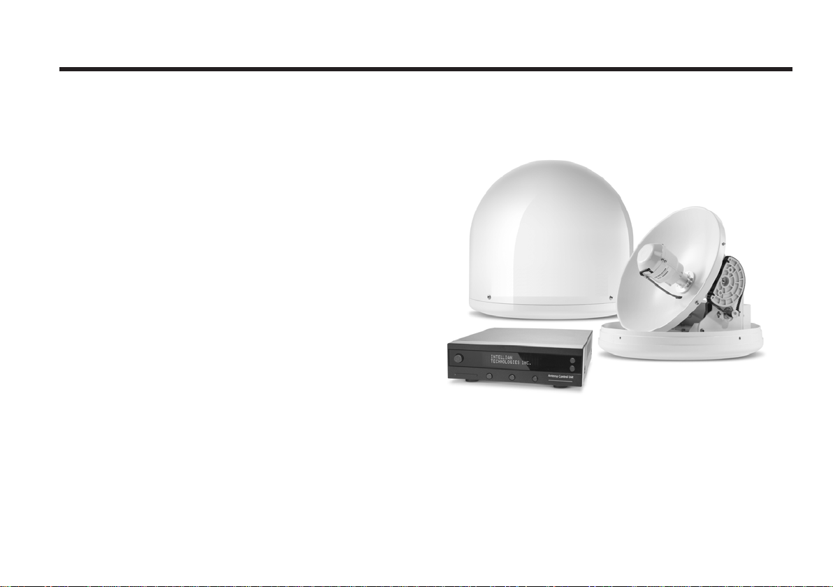
Introduction to Raymarine STV33
Raymarine STV33 is a digital satellite antenna system
designed specifically for all types of vessels (Anchored
or transit) to automatically identify, track and capture
satellite signals from the Digital Video Broadcasting (DVB:
the international standard for digital TV transmissions)
compatible satellites.
Specifically, Raymarine STV33 has Wide Range Search
(WRS) algorithm, which minimizes the search time during
initialization, and Dynamic Beam Tilting (DBT) technology,
which dynamically shapes the antenna beam to utilize
stabilization. While tracking the target satellite, DBT
technology uses a high-performance, constantly adjusting
sub-reflector which allows the antenna to remain relatively
still, eliminating the constant whine of stepper motors while
staying locked onto the satellites.
For simplicity and savings, the STV33 brings you hasslefree installation with its single cable design between the
antenna and the control unit. For flexibility, there is a second
RF connector on the antenna base. In addition, the STV33
has adopted a built-in GPS interface (NMEA 0183,) allowing
boaters to plug-in an external GPS to speed up acquisition
time.
7
Page 8

Raymarine Satellite TV Antenna Systems
Features of Raymarine STV33
Enjoy satellite broadcasts at sea
Raymarine STV33 is the most modern antenna system that
enables you to receive high quality broadcasting signals at
sea where the atmospheric and environmental conditions are
very harsh.
Fully automatic control system
The fully automatic control system allows you to simply turn
the power switch on, and have crystal clear, high quality
satellite television in motion or at anchor.
High quality antenna
High tech parabolic antenna technology has been adopted
for this antenna system, which is optimal for marine
conditions. This enables you to receive the optimal signal
level even when it is raining or snowing.
Fast and ecient search for the satellite
The WRS (Wide Range Search) algorithm allows for the
antenna system to search the satellite within the shortest
amount of time and to detect the satellite signal under any
position and within any directional movement of the ship.
Outstanding reliability
Raymarine STV33 provides a highly reliable system through
the implementation of a modularized design and the use of
strictly-proven components.
8
Easy installation
Raymarine STV33 uses only one RF cable for installation.
Power, RF, and Data signals transfer from the antenna to the
ACU through this single cable.
Compact size
Raymarine STV33’s small and compact size is perfect for
small vessels.
Ethernet Port for management
The Ethernet Port on the rear panel of the ACU enables
direct and simple network connection between a PC and the
ACU. By connecting to ISP or the modem linked with VSAT
systems, Raymarine STV33 can be monitored, controlled,
and diagnosed remotely from anywhere, anytime through the
TCP/IP protocol. This not only can save tremendous time but
also save the cost generated from the hundreds of routine
maintenance activities such as operating firmware upgrades,
tracking parameters resets, and system diagnostics.
Wireless Connectivity and Aptus mobile
The built-in WiFi enables the ACU to be wirelessly
connected. Any kind of wireless devices such as PCs,
laptops and smartphones can be used to connect to the ACU
and monitor, control and change the settings of the system
wirelessly. The Aptus mobile app is available for download to
access the ACU via Wi-Fi and operate the antenna from an
iPhone, iPad or other network devices.
iPhone and iPad are registered trademarks of Apple Inc.
Page 9
Basic System Configuration of Raymarine STV33
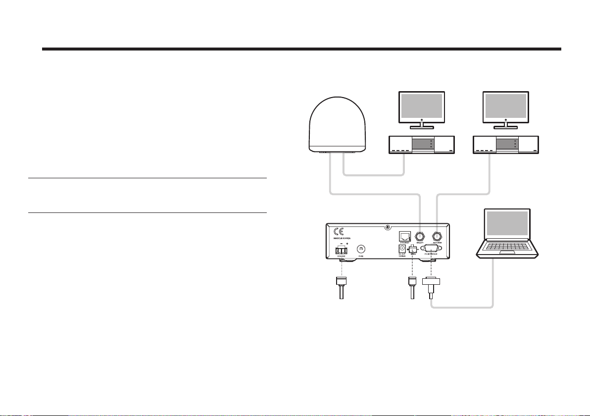
For your satellite TV system to function properly, the
system will have to be connected with all of the provided
components as shown on the right (Refer to the next chapter
‘Installation’ in this manual for more detailed connection
instructions). Separate purchase of a satellite receiver and a
TV is required.
Note: Dish Network and Bell TV users please refer to the
separate Dish Network MIM Installation and User Manual.
TV
(Not Supplied)
Satellite Receiver
(Not Supplied)
Antenna Control Unit
NMEA
Connection
DC Power on Vessel
(DC
- 9.0 - 30.0V)
(E.g. GPS)
Figure 01 : Basic Configuration with 2 Receivers
TV
(Not Supplied)
Satellite Receiver
(Not Supplied)
PC (Not Supplied)
9
Page 10
Raymarine Satellite TV Antenna Systems
Installation
The components of the Raymarine STV33 have been
designed to be modular so that it is suitable for simple
installation on all types of vessels.
System Components
Antenna Unit
The Raymarine STV33 system comprises the following
components for optimum search and reception of the satellite
signal.
• Mechanical Unit – manipulates the antenna to receive an
optimal satellite signal, regardless of the movement of the
vessel.
• Control Unit – controls mechanical operation of the antenna.
• RF Unit – transmits an optimum satellite signal to the receiver.
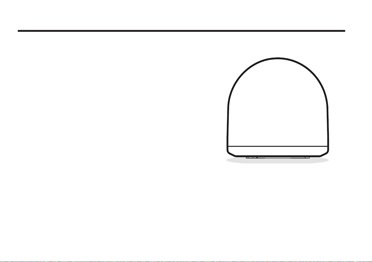
• Radome – protects the antenna from severe marine
environmental elements.
Figure 02 : Radome
10
Page 11
Antenna Control Unit (ACU)
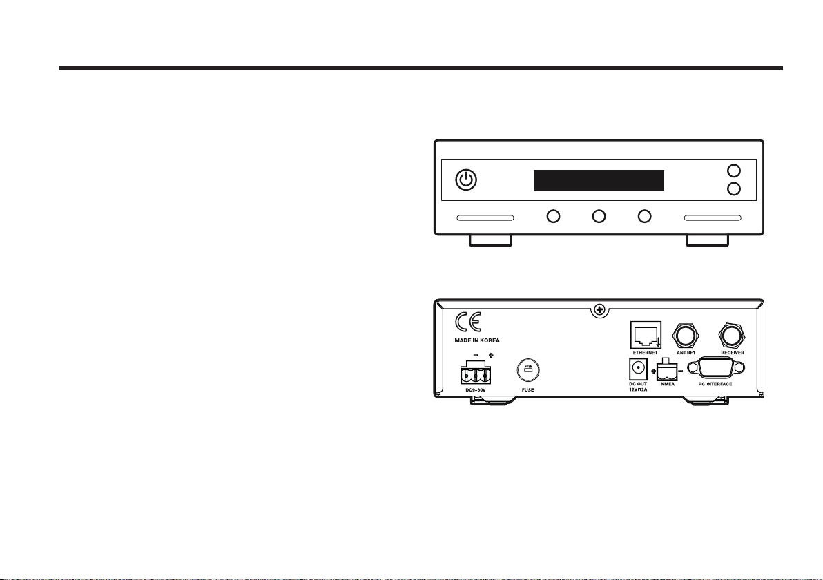
The Antenna Control Unit (ACU) provides the power to the
antenna and controls various settings of the antenna. The
digital VFD (Vacuum Fluorescent Display) allows for easy
operation of the ACU, even in the dark.
The functions of the ACU are as follows:
• Provides power to the antenna unit
• Monitors the antenna status
• Changes the target satellite
• Set up the user environment
• Set the current GPS information
• Set satellite information
• Perform self-diagnosis of the antenna
• Set up the interface with a PC
Front
Antenna Control Unit
Rear
Figure 03 : Front & Rear of ACU
11
Page 12
Raymarine Satellite TV Antenna Systems
Hex.Bolt
5
Flat Washer
5
Spring Washer
5
Hex. Nut
5
Item
Qty
Item
Qty
Size
Self-Tapping Screw
5
(M4 X 16L)
Machine Screw
5
(M3 X 8L)
Antenna
ACU
12
Installation Kit
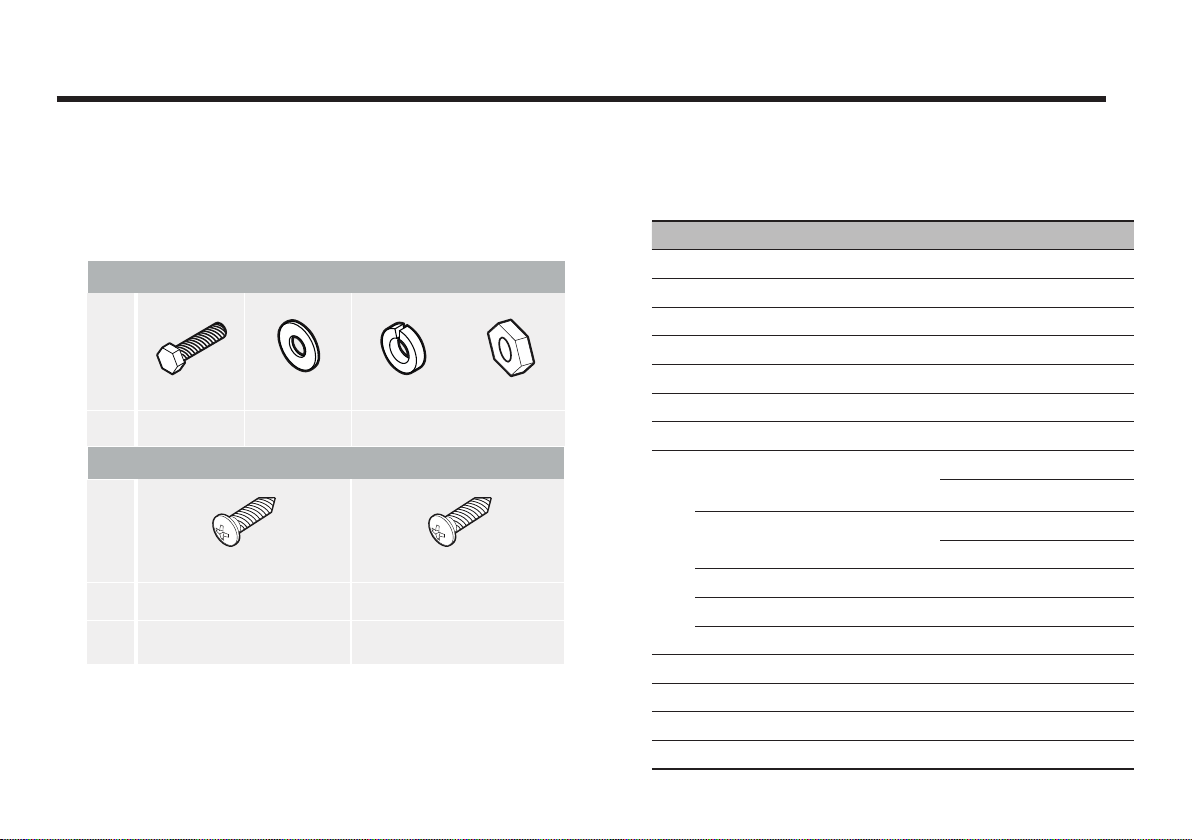
Contains the items required for securing the antenna unit and
ACU to the vessel.
Figure 04 : Installation Bolt Kit
Other Components
No Components Size Qty
1 ACU Bracket - 2
2 RG6(Antenna – ACU RF Cable) 15m 1
3 RG6(ACU – IRD Cable) 3m 1
4 Power Cable 10m 1
5 PC Serial Cable 1.8m 1
6 NMEA Connector 1.5m 1
7 Power Connector AK950-2 1
Hex Bolt
Tapping Screw
8
Flat Washer M6 10
Spring Washer M6 5
Nut M6 5
9 Aptus CD - 1
10 User Manual - 1
11 Mounting Template 1
12 Quick Installation Guide - 1
Figure 05 : List of the Supplied Parts
M6x35L 5
M6x50L 5
ø4x16L 5
ø3x8L 5
Page 13
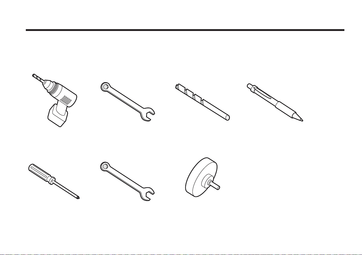
Tools Required for Installation
8 mm Drill Bit
Ø50 mm
Hole Saw
Pencil
Power Drill 11 mm Spanner
Cross-Head
Screwdriver 10 mm Spanner
Figure 06 : Required Tools for Installation
8 mm Drill Bit
Ø50 mm
Hole Saw
Pencil
13
Page 14
Raymarine Satellite TV Antenna Systems
Planning the Installation
Selection of Installation Site
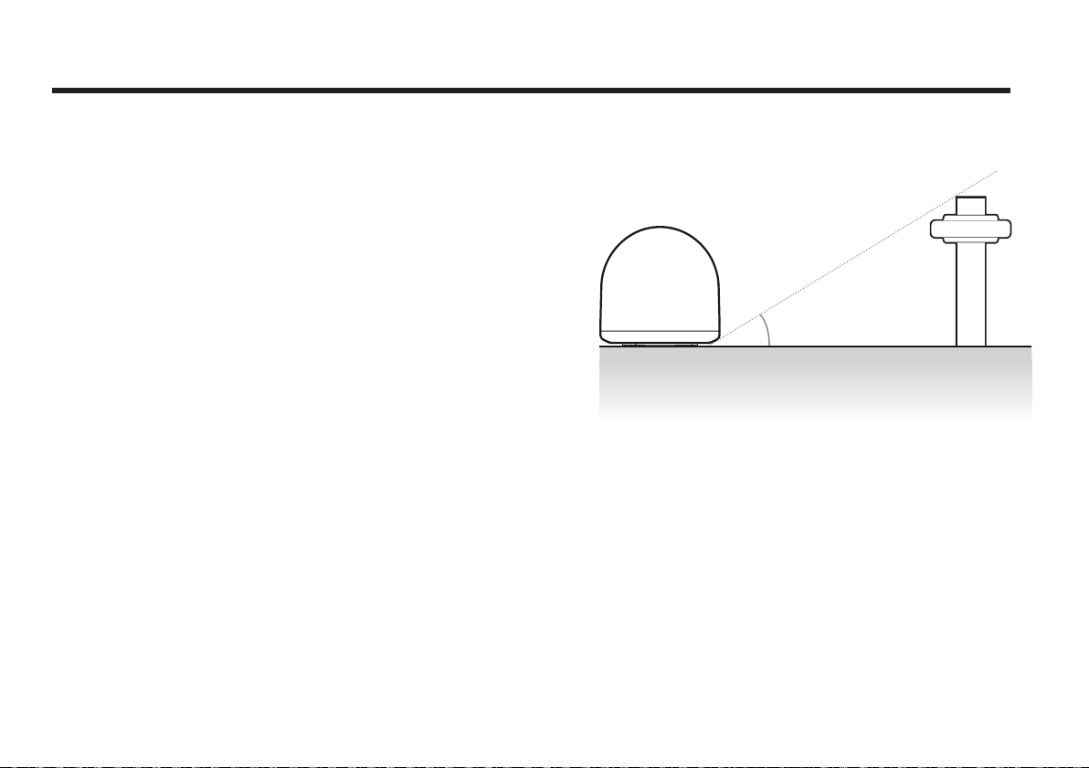
The antenna should be installed in a place where it has
an all-round clear view of the horizon. Ensure there are
no obstacles within 15 degrees above the antenna. Any
obstacles can prevent the antenna from tracking the
satellite’s signal (Refer to the drawing on the right).
15°
Do not install the antenna nearby the radar, especially
if they’re on the same plane, as their energy levels may
overload the antenna’s front-end circuits. It is recommended
to position the antenna at least 4 feet (1.2m) above or below
the level of the radar and a minimum of 15 feet (4.6m) away
from any high power short wave radars.
The mounting platform should be suitably rigid, and not
subjected to excessive vibration. The movement of the
antenna can be minimized by installing it at the center of
the vessel. For optimal performance of the antenna, it is not
recommended to install it at any corner of the vessel, where
the movement of the vessel is the greatest. Install the bottom
of the antenna parallel to the surface of the sea and fix it
tightly to the structure of the vessel.
When setting the antenna down, be careful not to damage
the RF connector. Striking the connectors on the bottom
directly will damage the connector.
14
Antenna unit Obstacle
Figure 07 : Elevation Limit of Obstacles
Page 15

Cables
Before installing the system’s cables, consider the following
points.
• All cables need to be well clamped and protected from
physical damage and exposure to heat and humidity.
• A cable with an acute bend is not allowed.
• Where a cable passes through an exposed bulkhead or
deckhead, a watertight gland or swan neck tube should be
used.
Power Requirements
To avoid potential damage to your system, adhere to the
following power requirements:
Extending the cables
The cables that have been supplied with your Raymarine
system should be of adequate length to complete the
installation on most boats.
Power Cable
This cable is supplied at a length of 10m.
RF Cable
This cable is supplied at a length of 15m. If a longer length is
required you should replace this cable with an extended RF
cable, available separately.
• Raymarine STV33 has been designed to work on a boat’s
power supply rated at 12V / 24V DC (acceptable range: 9~30
V DC).
• If your IRD(s) and television(s) require a 110V/240V AC
power supply, you will need to install a suitable DC to AC
converter to operate the unit(s) from your boat’s DC power
supply.
Note: Exceeding the indicated cable lengths will result in
reduced performance of your system.
15
Page 16
Raymarine Satellite TV Antenna Systems
Installation and Mounting of the Antenna
The method of installation and mounting of the antenna may
vary due to vessel design but the following procedures are
applicable in most situations, and will result in a secure and
eective installation.
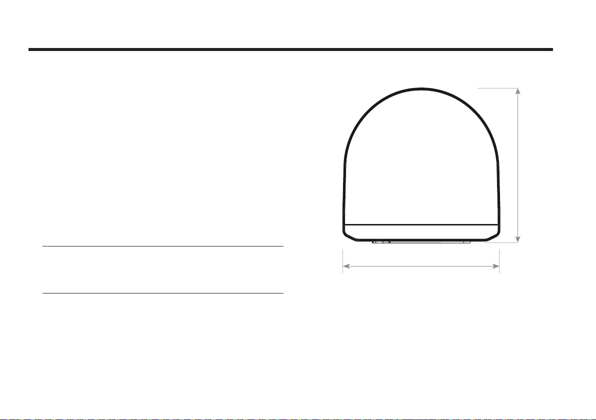
Confirmation of Size and Installation of Power Tower
• Confirm the height and diameter of the bottom surface of
the antenna before installing it.
• The space must be sucient for installing the antenna unit,
considering the height and diameter of the antenna.
• The height and the diameter of the bottom surface of the
antenna is shown in the following drawing. If possible, install
the antenna using a “power tower”, available separately.
Note: Before installing the antenna, open the radome and
remove the shipping constraints from the antenna interior.
Reinstall the radome before operating the system. The
system will not perform properly if the radome is open.
38.1 cm (15”)
Ø37 cm (14.7”)
Figure 08 : Radome Dimension of STV33
16
Page 17
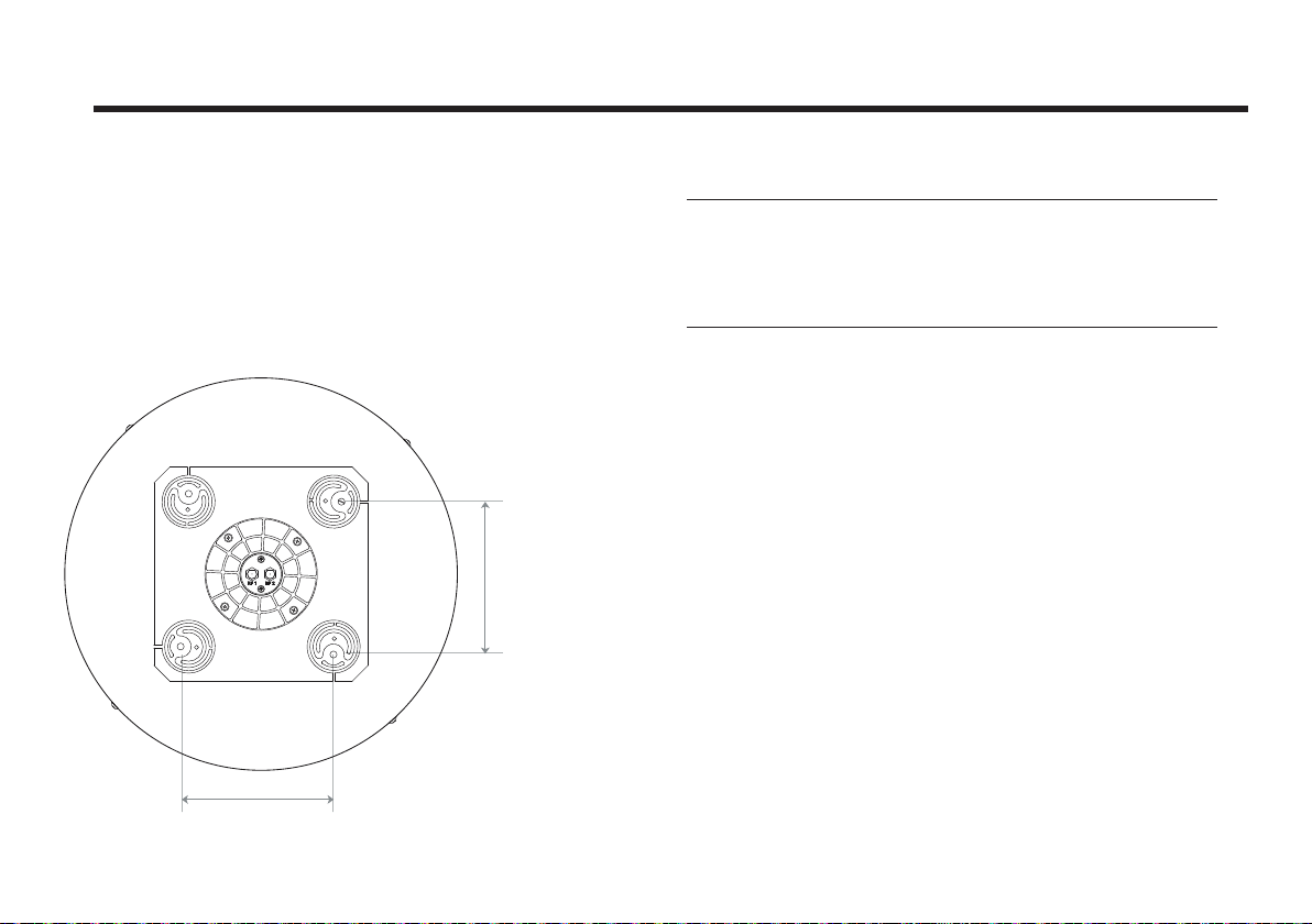
Mark the Antenna’s Parking Position
14.4cm (5.7”)
Referring to the supplied Mounting template, mark where
antenna is to be mounted onboard the ship (it must be a
flat surface), or on a separate “power tower” by drawing a
square of 14.4cm (5.7”)
14.4cm (5.7”)
Note:
If a “power tower” is not used to mount the antenna,
separate cable shocks and waterproofing measures must
be taken to protect the RF connector from being exposed to
sea water and external shocks. An exposed cable may cause
electric shock and cause serious damage to the equipment.
Figure 09 : Raymarine STV33
17
Page 18
Raymarine Satellite TV Antenna Systems
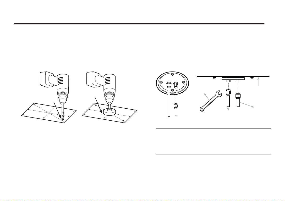
Securing Holes for Bolts and Cable Ways
Make 4 bolt holes of 8mm diameter, one at each corner of a
rectangle drawn as below, and make a circular hole of 50mm
diameter at the center of the rectangle through which the
cable will run.
Ø50mm
Ø 8mm
Drill
Figure 10 : Drilling Instruction
Hole Saw
Connection of the Cable
Remove the rubber cap from the RF connector. Connect the
RF cable to the RF connector under the base plate through
the access hole using an 11mm spanner. Be careful not to
over tighten, as you may damage the connector.
11mm
Spanner
RF1 Cable
Figure 11 : Connectors on Bottom of Antenna
Note: Do not use excessive force or overtighten when using
Antenna Unit
Optional
the spanner, as this will damage the threads. Be careful that
the connectors do not touch the mounting surface of the
antenna, this might cause a critical malfunction and serious
damage to the equipment.
18
Page 19
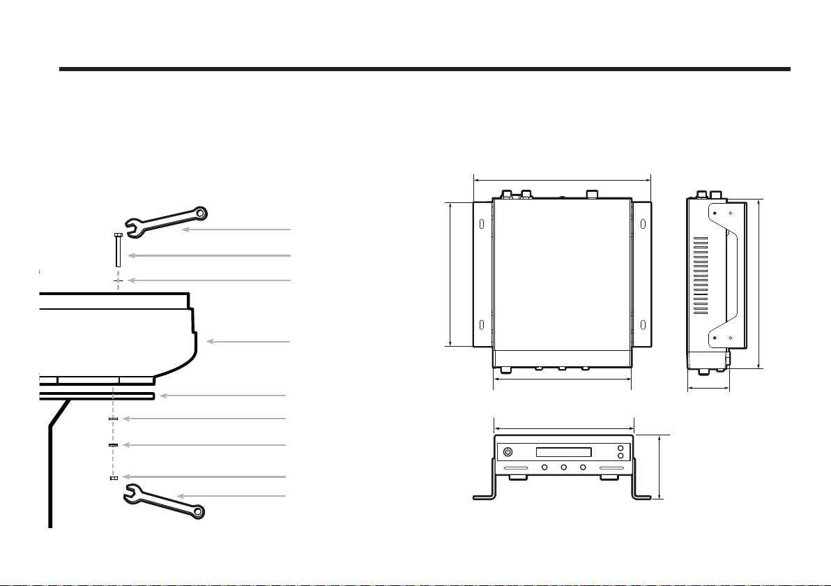
Mounting the Antenna
7.5 cm (2.95”)
Fix the antenna to the holes made before, as shown in the
drawing below by using the supplied hex head bolts (M6 X
35L), M6 spring washer, M6 flat washer and M6 Nut.
10mm Spanner
M6 Hex. Bolt
M6 Flat Washer
Radome Base
Installing the ACU
ACU Dimensions
22.8cm(9”)
18.5cm (7.3”)
21.7cm(8.5”)
Figure 12 : Mounting the Antenna
Deck
M6 Flat Washer
M6 Spring Washer
M6 Hex. Nut
10mm Spanner
17.8cm (7”)
17.8 cm (7”)
Figure 13 : Dimension of ACU
5.4cm (2.1”)
19
Page 20
Raymarine Satellite TV Antenna Systems
Selecting ACU Installation Site
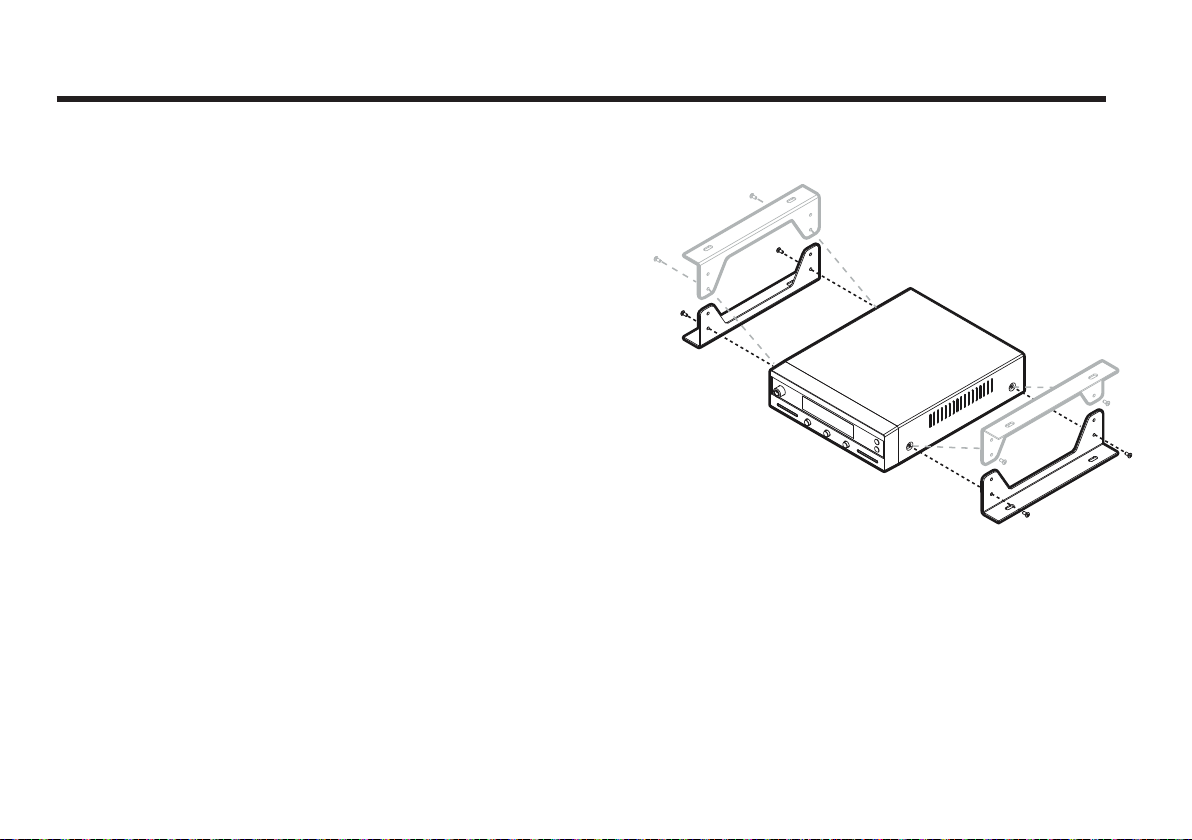
The ACU should be installed below deck, in a location that is:
• Dry, cool, and ventilated.
• Easily accessible from your main TV viewing area.
To Install the ACU
1. The ACU should be installed using the two supplied
mounting brackets which allow for a top or bottom mounting
configuration.
2. Using the self tapping screws supplied, attach the
mounting brackets to the sides of the ACU.
3. Place the ACU in the location where it is going to be
installed.
4. Connect the cables to the rear of the ACU.
5. Use a pencil to mark the 4 hole positions (two on each
side), and use the appropriate drill bit to drill them.
Figure 14 : Installation of ACU
20
Page 21
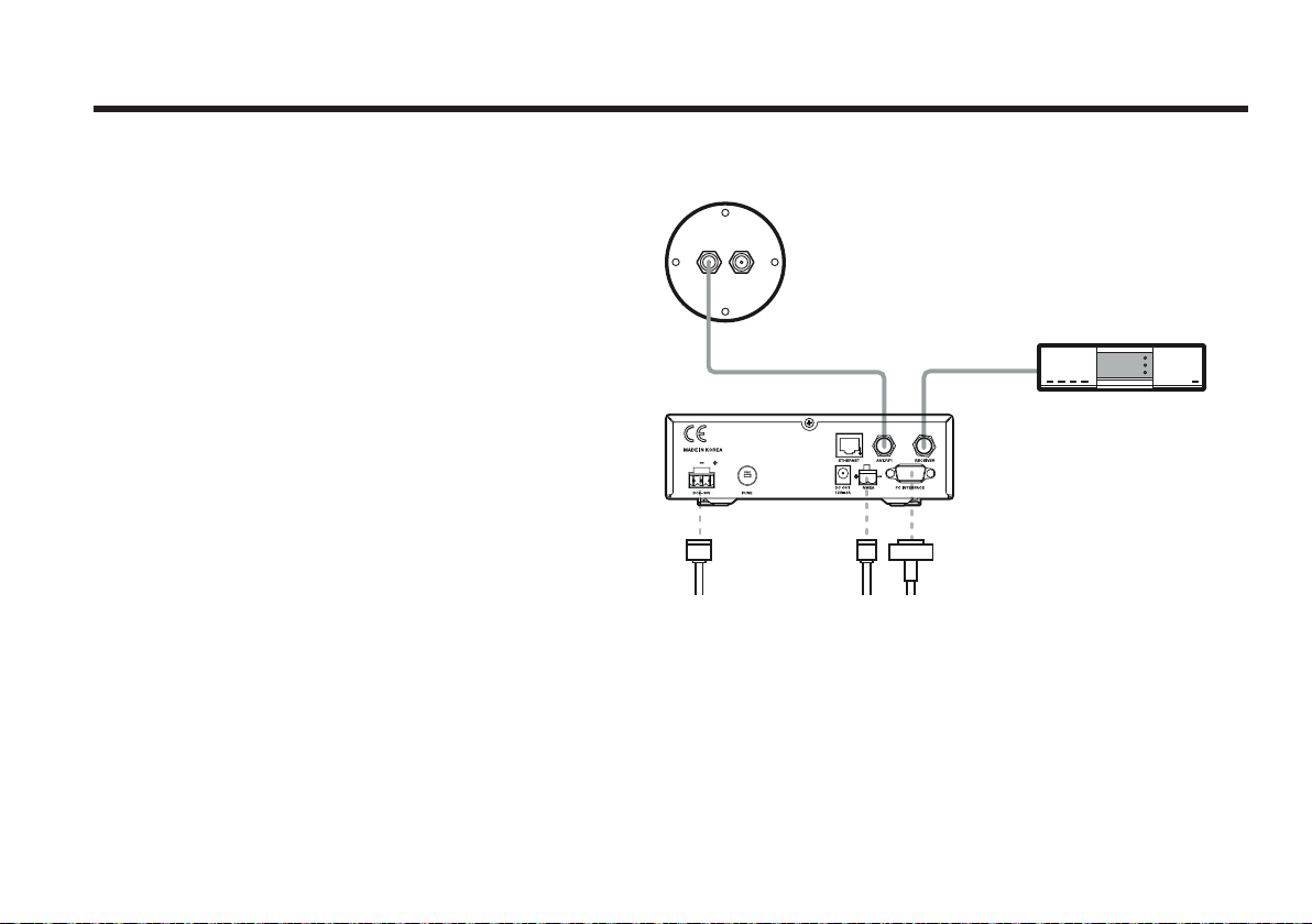
Connecting the System Cables
After installation and fixation of the antenna, connect the ACU to
the antenna. Refer to the drawing below to connect cables.
Single IRD Connection
• Connect the RF Cable (15m) from the RF 1 connector on the
antenna to the ANT. RF1 connector on the rear of ACU.
• Connect the ACU-IRD Cable (3m) from the RECEIVER
connector on the rear of the ACU to the RF on the IRD.
• Connect the power cable (10m) from the DC power
connector on the rear of ACU to a power source at 12V /24V
DC.
• Press the POWER ON switch in front of the ACU to start
operating the antenna system automatically.
RF1
RF2
ACU
DC Power Cable
RF Cable
Antenna Receiver
NMEA
Connection
(E.g. GPS)
ACU IRD Cable
PC Cable
Figure 15 : Single IRD Configuration
IRD (Not Supplied)
21
Page 22
Raymarine Satellite TV Antenna Systems
Antenna Receiver
DC Power Cable
PC Cable
ACU
RF1 RF2
RF Cable
ACU IRD Cable
IRD1 (Not Supplied)
IRD2 (Not Supplied)
NMEA
Connection
(E.g. GPS)
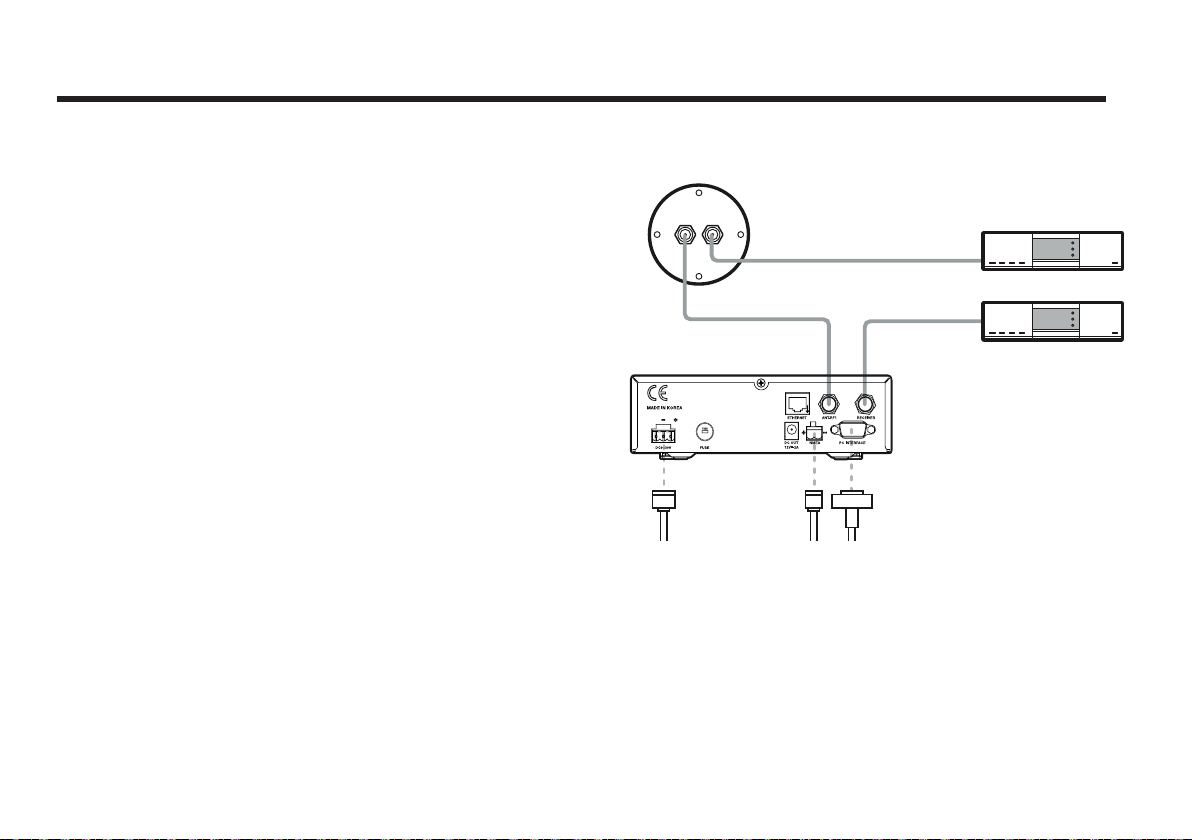
Twin IRDs Connection
You can connect two IRDs for your antenna as shown in the
following diagram. One of the IRD’s need to be set up with the
ACU in order to use another IRD without connecting the ACU.
Both IRD’s with and without an ACU connection can receive
any channels that are available from the tracked satellite.
As in the single IRD option, the RF cables from the antenna
base plate should be connected to ‘LNB’, ‘ANT’, or ‘Satellite In’
on the rear panel of the IRD.
Figure 16 : Dual-IRDs Configuration
22
Page 23
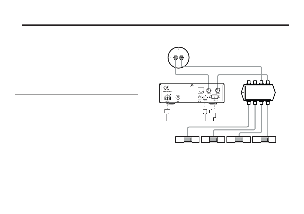
Multiple-IRDs Connection
In order to connect multi-IRD to the antenna, you will need
to purchase a suitable multiswitch. The multiswitch has to be
installed between the antenna unit and the IRDs as shown on
the right.
Note: The system can receive either “High Band” or “Low
Band” channels by using a multi-switch to connect more than
two receivers.
RF1 RF2
ACU
DC Power Cable
RF Cable
Antenna Receiver
NMEA
Connection
(E.g. GPS)
PC Cable
ACU IRD Cable
Multi switch
(Not Supplied)
IRD 2IRD 1
IRD 3
* IRD 1~4 : Not supplied
Figure 17 : Multi-IRDs Configuration
IRD 4
23
Page 24
Raymarine Satellite TV Antenna Systems
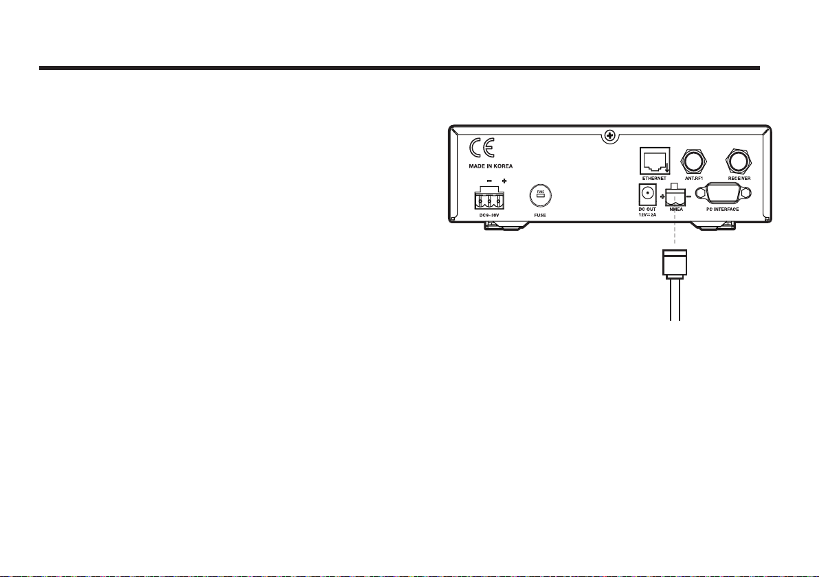
Connecting the System to a GPS
To improve satellite tracking, you can connect your satellite
TV system directly to your boat’s NMEA 0183 GPS system. To
do this you will need a cable with suitable lengths to connect
to your GPS system and you will need the green 2-way ACU
GPS connector supplied with your Raymarine STV33 Satellite
TV System.
To connect the system to a GPS
1. Remove the rubber band insulations on each cable and
connect a cable to each terminal of the 2-way connector.
2. Tighten the locking screws.
3. Connect the cable from the +ve (positive) terminal of the
ACU’s GPS connector to the NMEA OUT wire of the boat’s
GPS system.
4. Connect the cable from the –ve (negative) terminal of the
ACU GPS connector to the ground wire of the boat’s GPS
system.
5. Refit the ACU GPS connector to the rear of the ACU.
24
GROUND (-)NMEA OUT (+)
Figure 18 : NMEA 0183 GPS Connection
Page 25
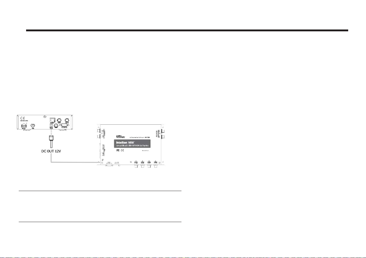
DC OUT port
The ACU provides DC OUT port for direct connection of an
MIM (Multi-satellite Interface Multi-switch), which requires DC
power input. The MIM can be connected to the ACU without
AC-DC Adaptor.
Figure 19 : DC out MIM
Note: The DC power cable is included in the component list of MIM.
Note: The STV33 antenna system is not compatible with SDM
devices.
25
Page 26
Raymarine Satellite TV Antenna Systems
Adjusting the LNB Skew Angle
(Linear Polarization Only)
LNB Skew Angle
The LNB skew angle only needs to be adjusted when the target
satellite is linear polarized. In order to receive the maximum
satellite signal level, the LNB skew angle must be adjusted
according to the calculation of current GPS location and target
satellite.
It only needs to be adjusted when changing from one satellite
to another, or when the vessel has traveled a significant
geographic distance. It should NOT need to be readjusted if
the vessel stays in the same location and is operating on the
same satellite.
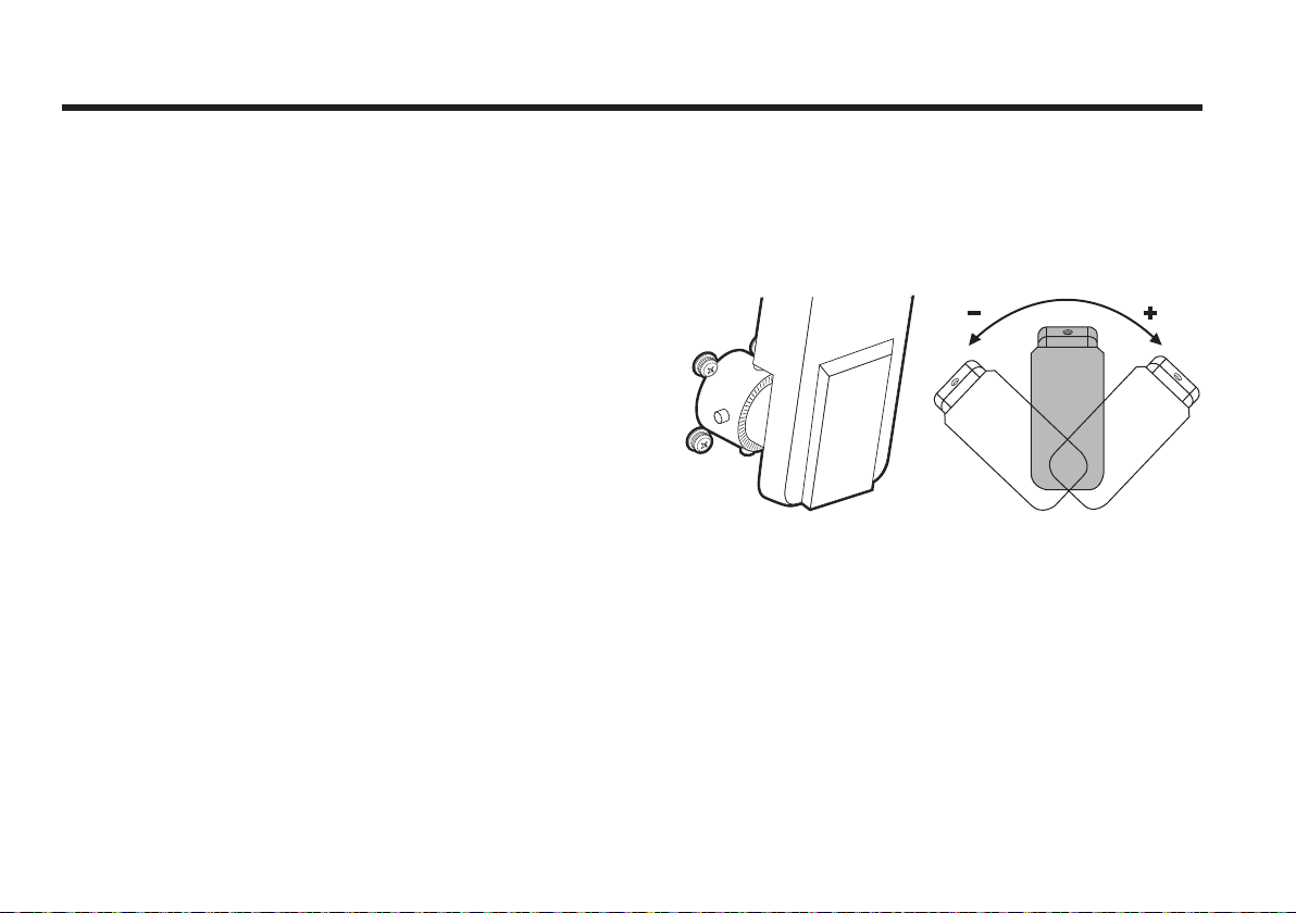
Skew Angle Adjustment for STV33
Polarization of your Raymarine STV33 antenna must be
accomplished manually by the following steps.
• Remove the upper part of the Radome after switching the
power OFF.
• Loosen the 3 screws that connect the LNB to the feed horn.
• Turn the LNB to place it to the angle indicated on the back of
the feed horn.
• Tighten the 3 screws.
Figure 21 : Manual Angle Adjustment LNB Skew
26
Page 27
PC to ACU Communication Setup
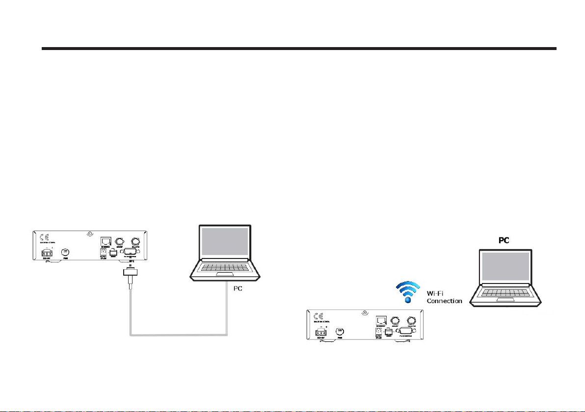
You can establish data communication between a PC and the
ACU using one of the following methods.
Serial Connection
Connection through Serial Port
1. Connect a 9-pin Serial cable from the PC INTERFACE
connector on the ACU to the 9-pin serial port on your PC.
2. If there is not a 9-pin serial port on the PC, use a USBSerial adapter.
Figure 22 : Serial Connection
Wi-Fi Connection
Setup Wi-Fi Connection
• Setting up the PC in order to access Wi-Fi
1. Connect Wi-Fi.
After clicking on the Windows Wireless Connection
icon, click on i-AP(default).
2. By default, the connection security is opened.
3. Use the ACU’s IP address to access Aptus
®
• Default: 192.168.1.223
Figure 23 : ACU to PC Wifi Connection
27
Page 28
Raymarine Satellite TV Antenna Systems
TCP/IP Connection
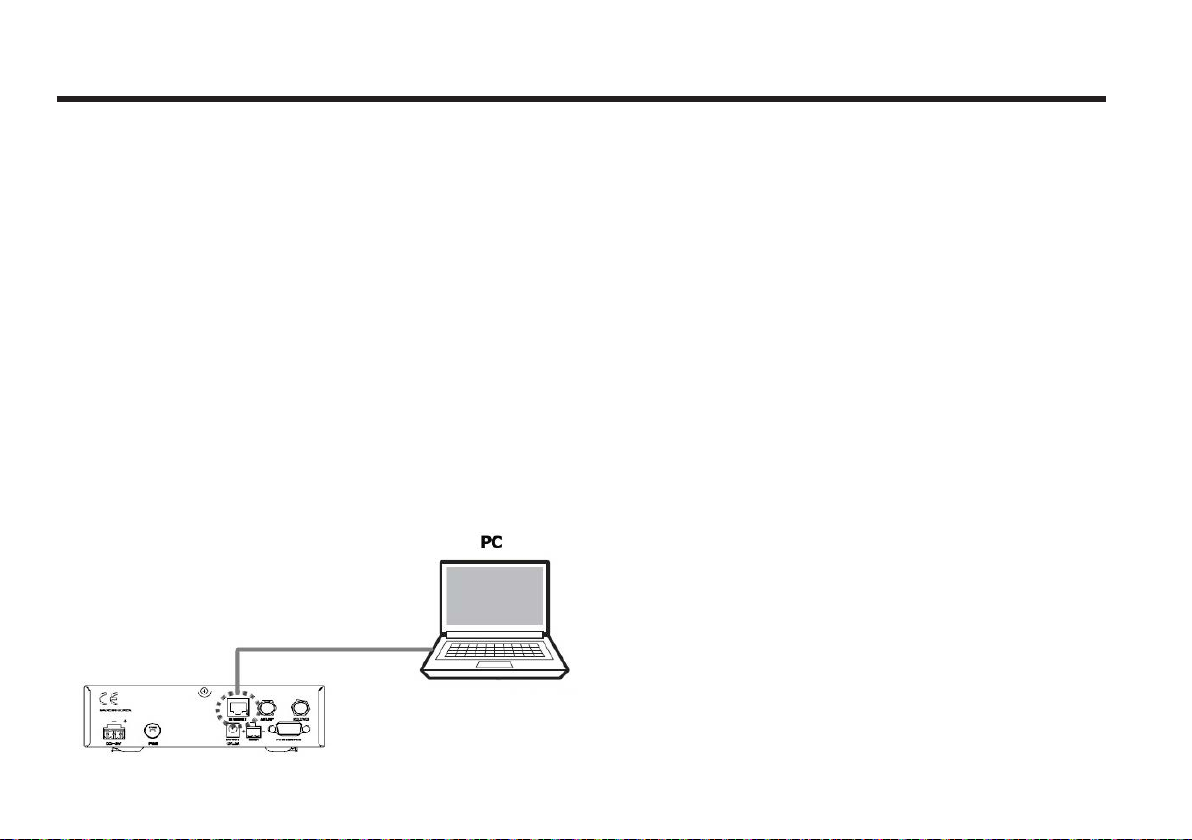
Connection through Rear Panel Ethernet Port
This method requires separate IP configuration on a PC.
1. Connect an Ethernet cable from a PC Ethernet port to
Ethernet port on the back of the ACU.
2. Go to Control Panel > Network and Sharing Center >
Change Adapter Settings and right-click on the Local Area
Connection, then click Properties.
3. Select TCP/IPv4, then click Properties.
4. Change the network settings on a PC;
• IP Address: 192.168. 0.222
• Subnet Mask: 255.255.255.0
• Gateway: 192.168.0.223
®
5. Use the ACU’s IP address to access Aptus
• Default: 192.168.0.223
.
Figure 24 : ACU to PC TCP/IP Connection
28
Page 29

Operation Instruction
Introduction
This section of the handbook describes how to setup your
Satellite TV System after installing the ACU. It includes the
following functions:
• System start up.
• Changing the default satellite.
• Monitoring the antenna status.
• Setting sleep mode.
• Entering setup mode.
• Setting the satellite pair.
• Editing satellite information.
• Setting the antenna parameter.
• Setting the LNB local frequency.
• Setting GPS.
• Setting the DiSEqC method.
• Display versions.
• Display power status.
• Setting antenna go position.
• Setting antenna move step.
• Setting remote control.
• Setting the factory default parameters.
• Performing diagnostic tests.
Note: Many of the above functions will only be required after
initial installation of your system.
29
Page 30
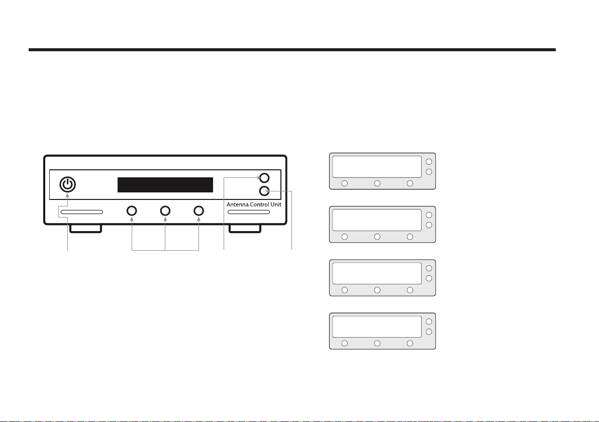
Raymarine Satellite TV Antenna Systems
Press to select
On-screen option
BACK
ENTER
POWER
Operation Using the ACU
ACU Soft Keys
Figure 25 : ACU Soft Keys
Normal Mode
Start Up
With the system installed and power applied, the ACU screen
will show the following sequence:
INITIALIZE ACU
INITIALIZE ANTENNA
SEARCH A: DTV101
B:DTV119 SETUP
TRACKING A: DTV101
B:DTV119 SETUP
1. Data communication is being
established between the antenna and
the ACU. The ACU is initialized.
2. The antenna is initialized.
3. The antenna is searching for Satellite A.
4. The antenna has located the satellite
and is now tracking.
30
Page 31
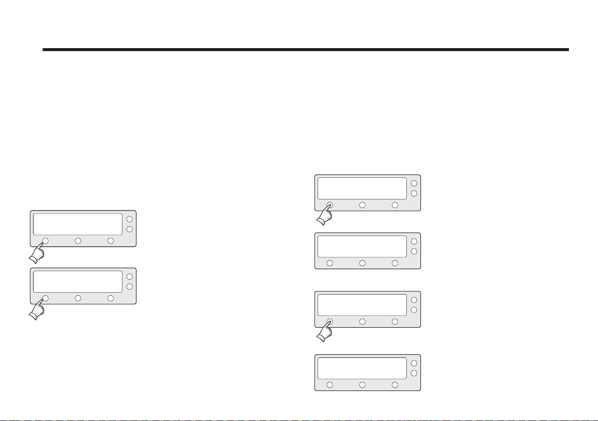
Changing Target Satellite
Your antenna is programmed with two candidates for target
satellites as the default Dual-sat mode. Use advanced Tri-sat
mode for targeting three satellites. To change the target
satellite, press the LEFT soft key. The target satellite is
changed and is automatically tracked by the antenna.
Default Dual-Sat Mode
TRACKING A: DTV101
B:DTV119 SETUP
1. Press LEFT soft key for tracking
Satellite B.
Advanced Tri-Sat Mode
TRACKING A: DTV101
B:DTV119 SETUP
TRACKING B: DTV119
DTV110# DTV101
1. Press LEFT soft key for tracking
Satellite B.
2. The antenna is tracking Satellite B.
TRACKING B: DTV119
A: DTV101 SETUP
2. The antenna is tracking Satellite B.
TRACKING B: DTV119
DTV110# DTV101
TRACKING C: DTV110#
DTV101 DTV119
3. Press LEFT soft key for tracking Satellite C.
4. The antenna is tracking Satellite C.
31
Page 32
Raymarine Satellite TV Antenna Systems
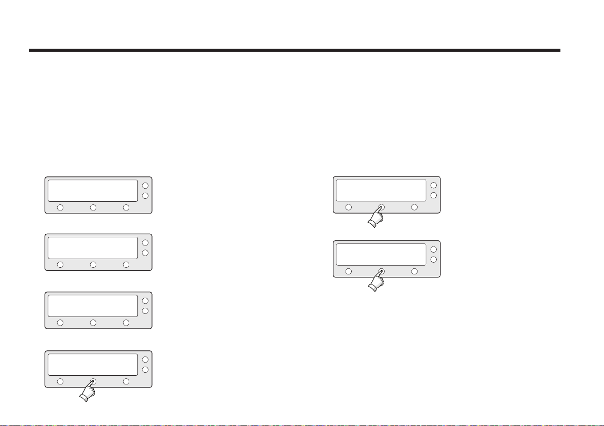
Monitoring the Current Status of the Antenna
While the power is ON on the Raymarine STV33, ACU
displays the status of the antenna. The various ACU displays
may be shown according to the current status of the antenna.
SEARCH A: DTV101
B:DTV119 SETUP
TRACKING A: DTV101
B:DTV119 SETUP
ANTENNA IS UNWRAPING
B:DTV119 SETUP
TRACKING A: DTV101
B:DTV119 SETUP
32
1. The antenna is searching Satellite A.
2. The antenna is tracking Satellite A.
3. The antenna is winding/unwinding the
cables in
the antenna.
4. The antenna is again tracking Satellite
A. Press center soft key to display
position detail.
AZ : ###.# EL : ##.#
SIGNAL : ### ● [VL]
###.##E ##.##N
5. Antenna position detail and signal
strength are
displayed.
6. Press center soft key to display
current GPS
information.
Page 33
Setup Mode
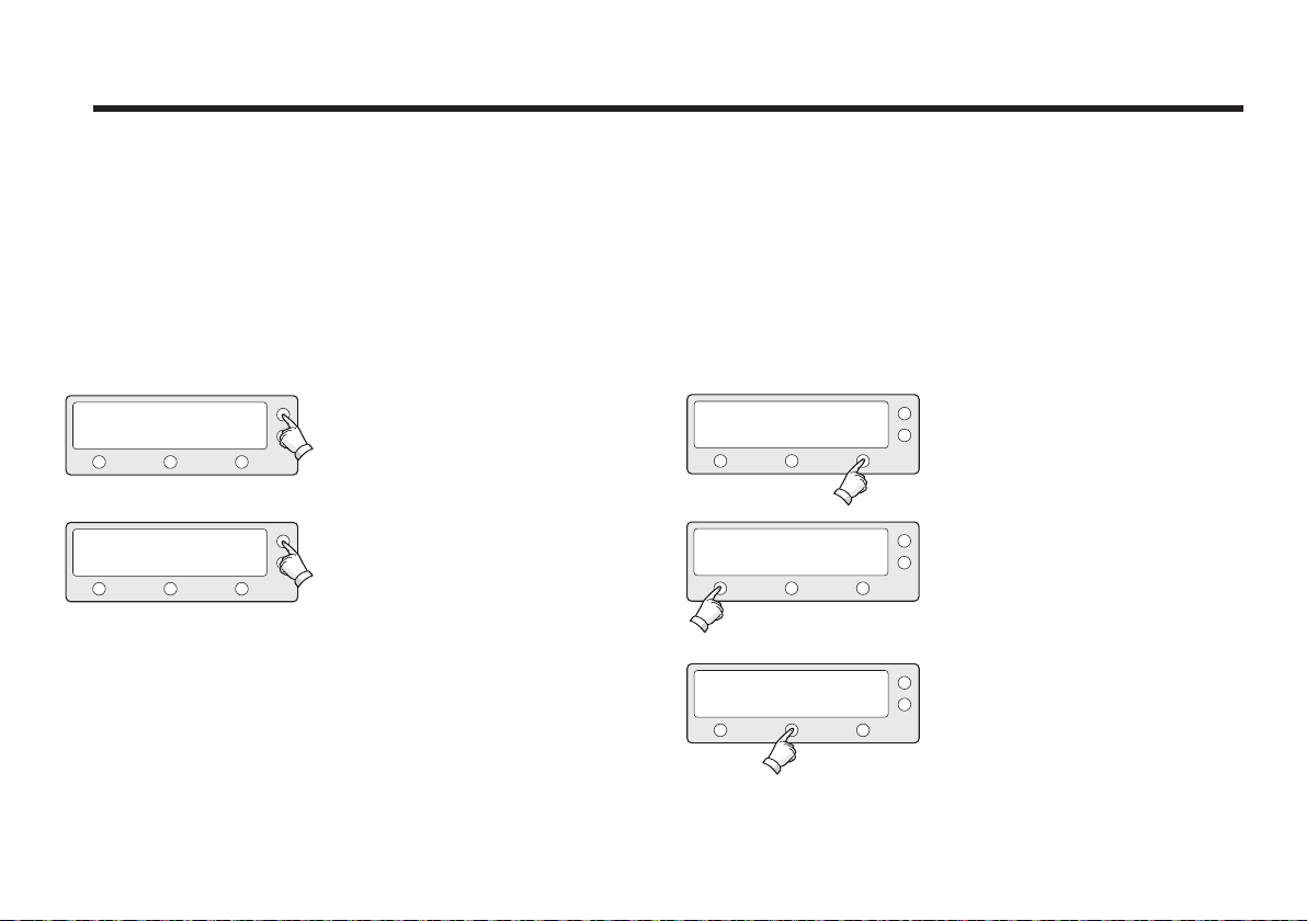
Sleep Mode
If the antenna loses the tracking satellite while in sleep
mode, sleep mode will be cancelled.
TRACKING A: DTV101
B: DTV119 SETUP
TRACKING A: DTV101
||B: DTV119 SETUP
1. Press BACK to enter sleep mode.
2. Press BACK again for exiting sleep
mode.
Begin Setup Mode
To enter the Setup Mode simply follow the instructions
below.
TRACKING A: DTV101
B:DTV119 SETUP
SETUP MODE ?
YES NO
SET SAT PAIR ?
PREV NEXTYES
1. With the antenna tracking. press
SETUP.
2. Press YES to enter setup mode.
3. Press YES to set the satellite pair.
33
Page 34
Raymarine Satellite TV Antenna Systems
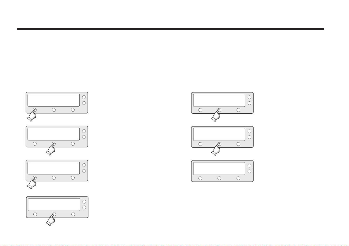
Setting the Satellite Pair
You can change the satellite pair if you decide to receive
satellite television service from a dierent service provider.
34
SETUP MODE ?
YES
SET SAT PAIR ?
PREV
YES
PREV NEXTSELECT
YES
SET TRIPLE SAT ?
SAT A : DTV101
NO
NEXT
NO
1. Press YES to enter setup mode.
2. Press YES to set satellite pair.
3. Press YES to set triple satellites.
4. Set satellite A
Press PREV to show previous satellite
name.
Press SELECT to set chosen satellite
to SAT A.
Press NEXT to show next satellite
name.
SAT B : DTV119
PREV
SAT C : DTV110#
PREV
YES
SELECT
SELECT
SAVE ?
NEXT
NEXT
NO
5. Set satellite B
Press PREV to show previous satellite
name.
Press SELECT to set chosen satellite
to SAT B.
Press NEXT to show next satellite.
6. Set satellite C
Press PREV to show previous satellite
name.
Press SELECT to set chosen satellite
to SAT C.
Press NEXT to show next satellite
name.
7. Press YES to save selections.
Press NO to cancel and return to main
setup mode.
Page 35
Setting GPS
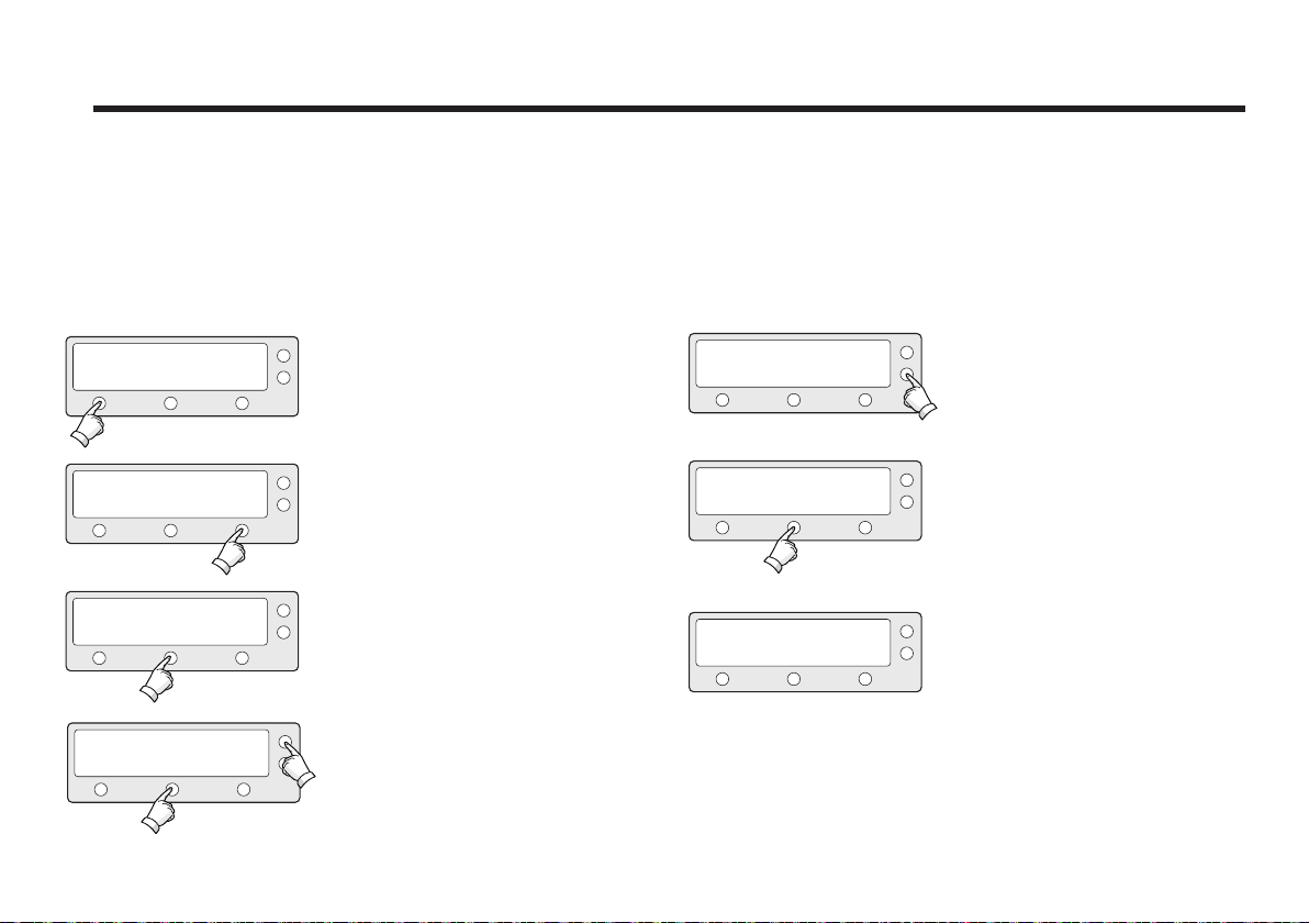
It is possible to set up and modify the GPS information, which
enhances the antenna functionality.
SETUP MODE ?
YES
SET SAT PAIR ?
PREV
PREV
YES
SET GPS ?
YES
LONGITUDE ###.## E
INPUT
-
NO
NEXT
NEXT
1. Press YES to enter setup mode.
2. Press NEXT to enter GPS setup
mode.
X1
LONGITUDE ###.## E
INPUT
-
LATITUDE ##.## N
INPUT
-
+
+
5. Press ENTER to move to next screen.
Press BACK to move to previous
screen.
6. Input the latitude data.
+ increases the value. - decreases the
value.
Change the underscored digit using
the +/- buttons.
Press INPUT to accept the value and
move to next digit.
3. Press YES to set GPS.
YES
SAVE ?
NO
Press BACK to move to previous digit.
7. Press YES to accept data.
Press NO to cancel and return to main
setup mode.
4. Input the longitude data.
+
+ increases the value. - decreases the
value.
Change the underscored digit using
the +/- buttons.
Press INPUT to accept the value and
move to next digit. Press BACK to move
to previous digit.
35
Page 36
Raymarine Satellite TV Antenna Systems
Edit Satellite Information
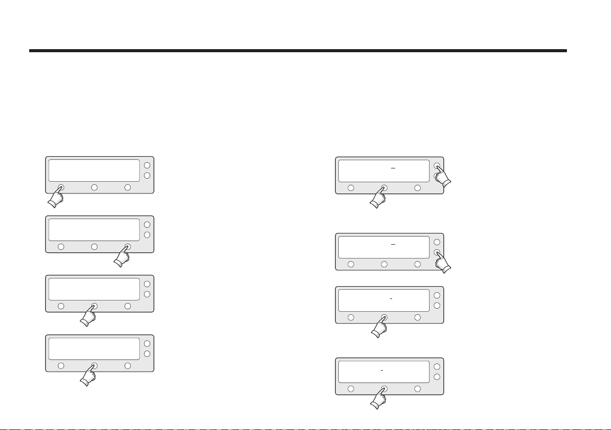
It is possible to modify the existing satellite information and
input new satellite information into the ACU as well. It is not
recommended for a novice satellite service user to use this
mode.
SETUP MODE ?
YES
NO
1. Press YES to enter setup mode.
SAT NAME : DTV101
-
INPUT
+
5. Input the satellite name.
+ increases the value. - decreases the
value.
Change the underscored digit using
the +/- buttons.
Press INPUT to accept the value and
move to next digit.
Press BACK to move to previous digit.
6. Press ENTER to move to next screen.
Press BACK to return previous screen.
7. Input the satellite position.
+ increases the value. - decreases the
value.
SET SAT PAIR ?
PREV
EDIT SAT INFO ?
PREV
YES
YES
NEXT
NEXT
2. Press NEXT twice to enter edit satellite info
mode.
X2
3. Press YES to edit satellite info.
SAT NAME : DTV101
-
INPUT
LONGITUDE 124.00 E
-
INPUT
+
+
Change the underscored digit using
the +/- buttons.
SAT NAME : DTV101
PREV
SELECT
36
NEXT
4. Set the satellite name.
PREV - Shows previous satellite name.
SELECT - Select the displayed satellite
for editing.
NEXT - Shows next satellite name.
Press ENTER to move to next screen.
VER LOW 12598 21096
-
+INPUT
Press INPUT to accept the value and
move to next digit.
Press BACK to move to previous digit.
8. Input the tracking frequency (MHz) and
symbol rate (KHz) for vertical low band.
Page 37
-
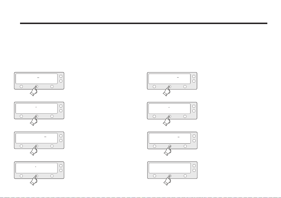
NID 0x0003
INPUT
9. Input the network ID (NID) for vertical
+
low band.
VER HIGH NID 0x0003
-
INPUT
+
13. Input the network ID (NID) for vertical
high band.
HOR LOW 12523 21096
-
INPUT
HOR LOW NID 0x0003
-
INPUT
VER HIGH 12598 21096
-
INPUT
10. Input the tracking frequency (MHz)
+
and symbol rate (KHz) for horizontal low
band.
11. Input the network ID (NID) for horizontal
+
low band.
12. Input the tracking frequency (MHz)
+
and symbol rate (KHz) for vertical high
band.
HOR HIGH 12523 21096
-
INPUT
HOR HIGH NID 0x0003
-
INPUT
VERIFY : DSS DECODE
PREV
SELECT
+
+
NEXT
14. Input the tracking frequency (MHz)
and symbol rate (KHz) for horizontal
high band.
15. Input the network ID (NID) for horizon-
tal high band.
16. Select the Verification Method*
of
tracking
satellite.
PREV - Shows previous method.
SELECT - Set the displayed method.
NEXT - Shows next method.
37
Page 38
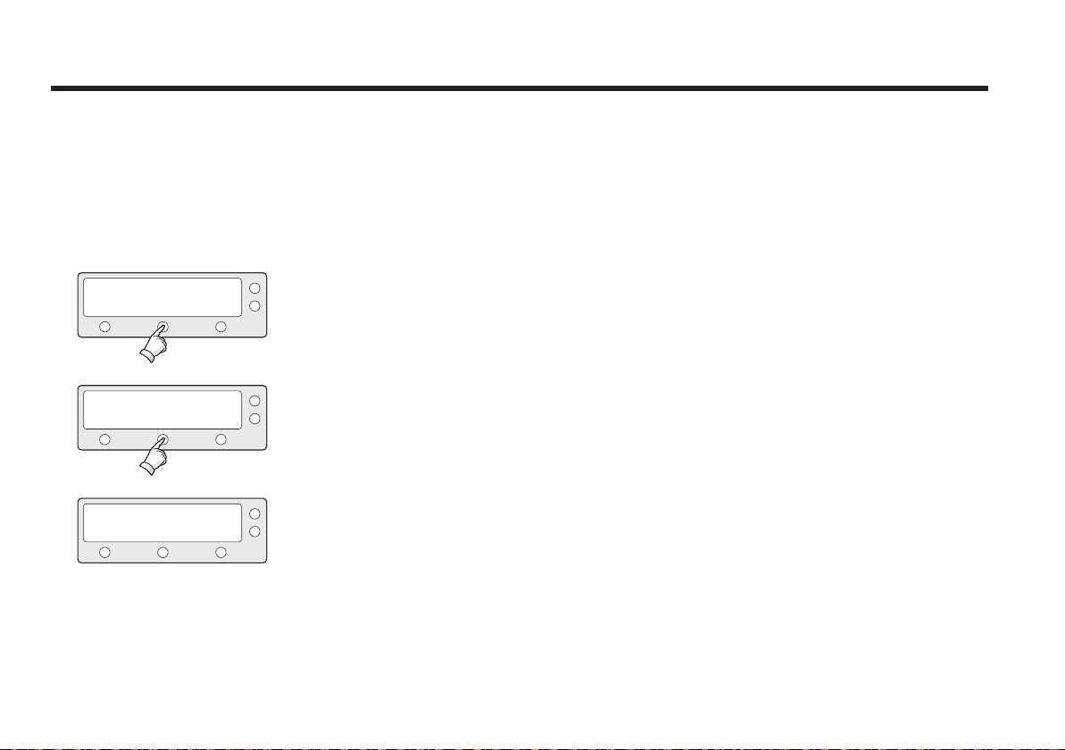
Raymarine Satellite TV Antenna Systems
VOLTAGE : AUTO
PREV
SELECT
NEXT
17.
Select the
Voltage Supply Method*
(AUTO is recommended)
LNB.
to
Verification Method*
SIGNAL - use only signal level for tracking
DVB LOCK - use only DVB Lock signal for tracking
DVB DECODE - verify satellite using DVB decoding method for tracking
DSS DECODE - decode only DSS Lock signal for tracking
AGC AFTER DECODE - for tracking Ka-Band satellite
DISEQC : ONLY 22KHz
PREV
SELECT
NEXT
18. Select the DISEQC Method*. (AUTO
is recommended)
Voltage Supply Method*
AUTO – Supply 13V or 18V to LNB
ONLY 13 V - always supply 13 V to LNB
ONLY 18 V - always supply 18 V to LNB
DISEQC Method*
AUTO – Supply 0KHz tone or 22KHz tone to LNB
ONLY 0 KHz – always supply 0KHz tone to LNB
SAVE?
YES
38
NO
19. Press YES to save the input information. Press NO to cancel and return to
main setup mode.
ONLY 22 KHz – always supply 22KHz tone to LNB
Page 39
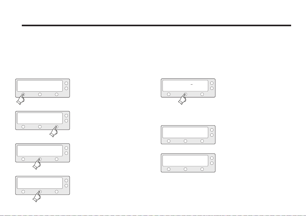
Setting the Antenna Parameters
It is not recommended for a novice satellite service user to
use this mode. Consult Raymarine for changing antenna
parameters.
SETUP MODE ?
YES
SET SAT PAIR ?
PREV
PREV
PREV
YES
SET ANT PARAMETER ?
YES
PARAM: SCAN OFFSET
YES
NO
NEXT
NEXT
NEXT
1. Press YES to enter setup mode.
2. Press NEXT three times to enter set
antenna parameter mode.
X3
3. Press YES to set antenna parameter.
4. Select the PARAM*.
PREV - Shows previous parameter.
SELECT - Set the displayed parameter.
NEXT - Shows next parameter.
Press ENTER to move to next screen.
WRS LEVEL : 0500
-
INPUT
ANOTHER PARAMETER
YES
SAVE ?
YES
NO
NO
5. Input the WRS LEVEL.
+
+ increases the value. - decreases the
value.
Change the underscored digit using
the +/- buttons.
Press INPUT to accept the value and
move to next digit.
Press BACK to move to previous digit.
Press ENTER to move to next screen.
6. Press YES to set up another parameter.
Press NO to cancel and return to main
setup mode.
7. Press YES to save the input information.
Press NO to cancel and return to main
setup mode.
39
Page 40

Raymarine Satellite TV Antenna Systems
PARAM*
Scan Oset
Track Scale
Detect Level
WRS Level
Track Oset
Power Level
40
The scan oset is to oset the angle dierence
between the black marker on the sub-reflector and
the optical sensor.
The track scale is to control the tracking speed while
antenna is tracking the satellite.
The detect level is to set the satellite signal
detection level.
The WRS level is to set the WRS detection level.
The tracking oset is to oset the satellite signal
tracking level.
The power level is to distinguish the voltage between 13
V and 18 V.
DiSEqC
Level
Oset RH-LH
EL Oset
Use WRS
Oset
Dierence
The DiSEqC level is to distinguish 0KHz tone and
22KHz tone.
The oset RH-LH is to oset the signal dierence
between RHCP and LHCP.
The EL oset is to oset the angle dierence
between the mechanical elevation angle and actual
elevation angle.
Use WRS is to determine whether the system uses
WRS level or not. “Use WRS” and “WRS Level” are
pair functions.
Oset dierence is to determine whether the system
to uses “Oset RH-LH” or not. “Oset Dierence”
and “Oset RH-LH” are pair functions.
Page 41
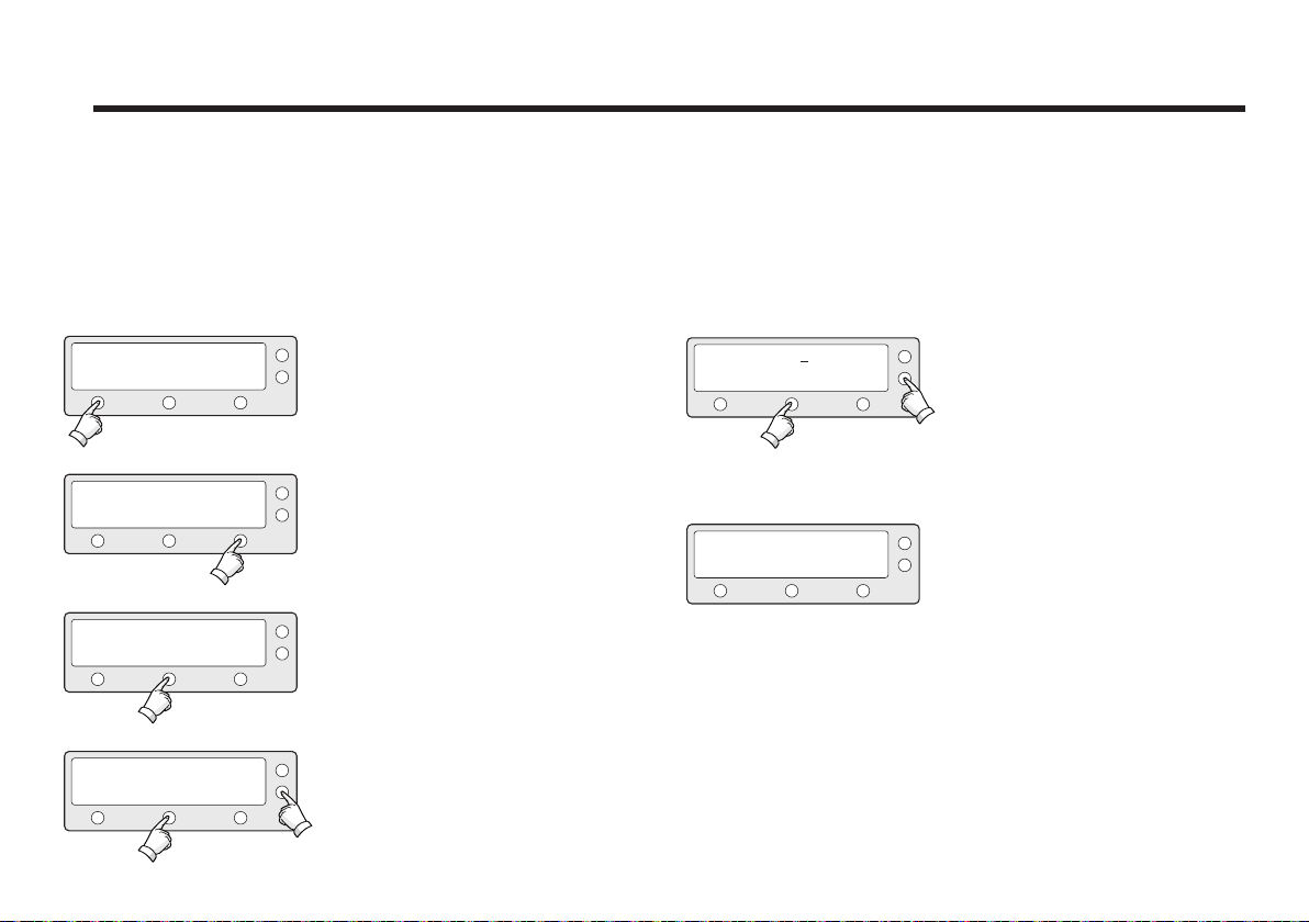
Setting the LNB Local Frequency
It is possible to select a local frequency from ACU. This mode
is not recommended for novice satellite service users.
Case1. Single band LNB is used.
SETUP MODE ?
YES
SET SAT PAIR ?
PREV
SET LOCAL FREQ ?
PREV
LNB TYPE : SINGLE
PREV
SELECT
YES
YES
NO
NEXT
NEXT
NEXT
1. Press YES to enter setup mode.
2. Press NEXT four times to enter set
local
frequency mode.
X4
3. Press YES to set local frequency.
4. Select the LNB Type* - SINGLE.
PREV - Shows previous LNB type.
SELECT - Set the displayed LNB type.
NEXT - Shows next LNB type.
Press ENTER to move to next screen.
LOCAL FREQ: #####MHz
-
INPUT
SAVE ?
YES
NO
5. Input the local frequency of LNB.
+
+ increases the value. - decreases the
value.
Change the underscored digit using
the +/-buttons.
Press INPUT to accept the value and
move to next digit.
Press BACK to move to previous digit.
Press ENTER to move to next screen.
6. Press YES to accept the data.
Press NO to cancel and return to main
setup mode.
41
Page 42
Raymarine Satellite TV Antenna Systems
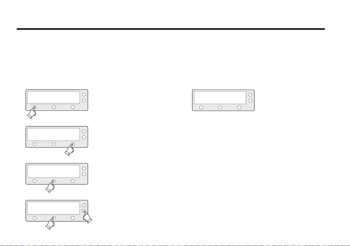
Case 2. Universal LNB is used (Low band local frequency
9750 MHz / High band local frequency 10600 MHz).
YES
PREV
SETUP MODE ?
SET SAT PAIR ?
YES
NO
NEXT
1. Press YES to enter setup mode.
2. Press NEXT four times to enter set
local frequency mode.
X4
SAVE ?
YES NO
LNB Type*
SINGLE: Single Band LNB
Asia 11300 MHz, Japan 10678 MHz, Korea 10750 MHz,
America 11250 MHz
5. Press YES to accept the data.
Press NO to cancel and return to
main setup mode.
UNIVERSAL : Universal LNB
Low band local frequency - 9750 MHz
SET LOCAL FREQ ?
PREV
PREV
YES
LNB TYPE : UNIVERSAL
SELECT
NEXT
NEXT
3. Press YES to set local frequency.
4. Select the LNB Type* - UNIVERSAL.
PREV - Shows previous LNB type.
SELECT - Set the displayed LNB type.
High band local frequency - 10600 MHz
NEXT - Shows next LNB type.
Press ENTER to move to next screen.
42
Page 43
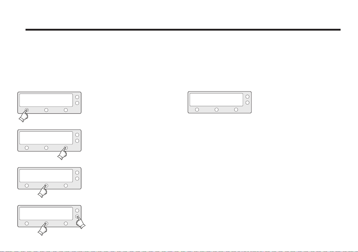
Setting the DiSEqC Method
DiSEqC selection can be made from ACU. It is not recommended for a novice satellite service user this mode.
SETUP MODE ?
YES
SET SAT PAIR ?
PREV
PREV
PREV
YES
USE DISEQC ?
YES
DO NOT USE DISEQC
NO
NEXT
NEXT
NEXT
1. Press YES to enter setup mode.
2. Press NEXT five times to enter DISEQC mode.
X5
3. Press YES to use DISEQC.
4. Select the DiSEqC Method*
PREV - Shows previous DiSEqC
Method.
SELECT/ENTER - Set the displayed
DiSEqC method.
NEXT - Shows next DiSEqC Method.
Press ENTER to move to next screen.
SAVE ?
YES NO
5. Press YES to accept the selection.
Press NO to cancel and return to main
setup mode.
DiSEqC Method*
DO NOT USE DISEQC - DiSEqC is not being used.
USE TO CHANGE BAND - DiSEqC is being used to change to low and high
band.
USE TO CHANGE SAT - DiSEqC is being used to change tracking satellite.
43
Page 44
Raymarine Satellite TV Antenna Systems
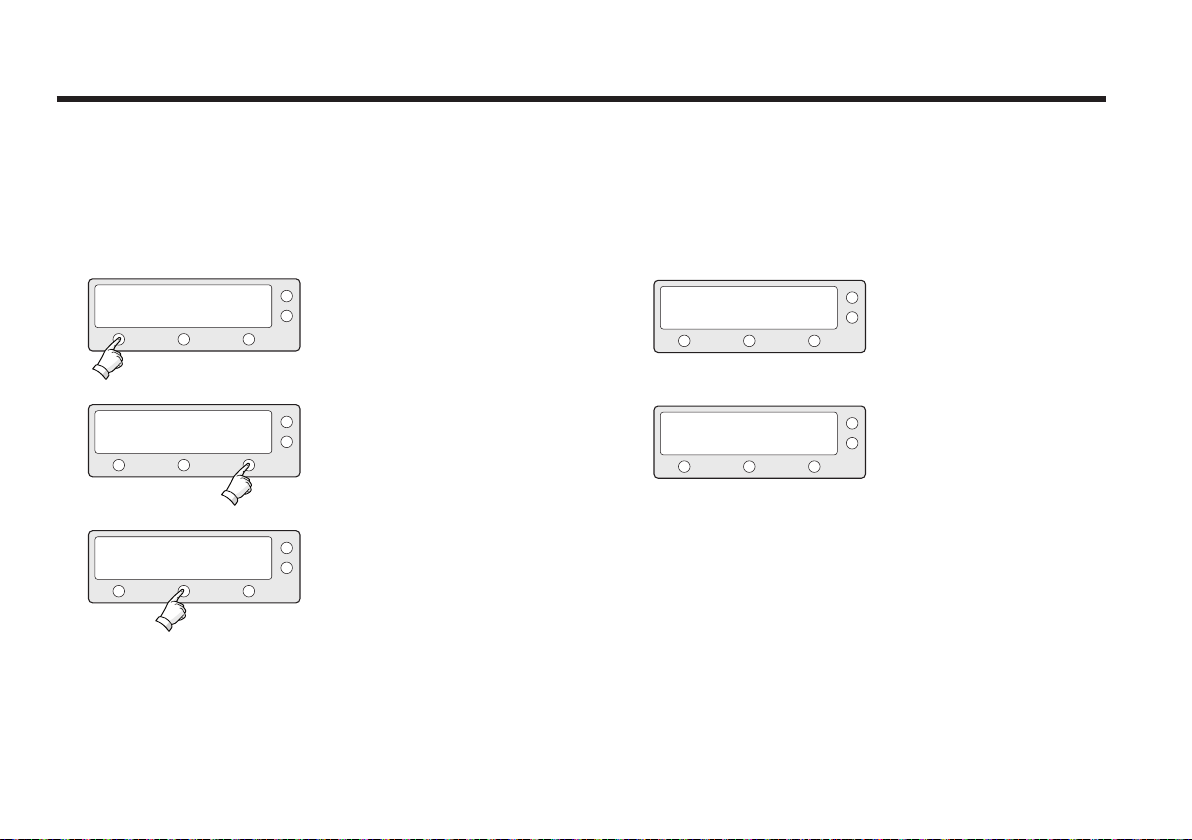
Setting the Use of DiSEqC 1.2
If DiSEqC 1.2 protocol is in use on your IRD, enable the
DiSEqC 1.2 setting on the ACU to process the DiSEqC 1.2
command.
1. Press YES to enter setup mode.
2. Press NEXT six times to enter the Use
DiSEqC 1.2 menu.
X6
YES
PREV
SETUP MODE ?
SET SAT PAIR ?
YES
NO
NEXT
USE DISEQC 1.2 : NO
PREV SELECT
SAVE ?
YES
NEXT
NO
4. Set the USE DiSEqC 1.2 to a desired
option*.
PREV - Shows previous option (YES/NO)
SELECT/ENTER - Set the displayed option for DiSEqC 1.2.
NEXT - Shows next option (YES/NO)
Press ENTER to move to next screen.
5. Press YES to accept the data.
Press NO to cancel and return to main
setup mode.
USE DISEQC 1.2 ?
PREV
44
YES
NEXT
3. Press YES to set the use of DiSEqC
1.2.
Options for ‘USE DiSEqC 1.2’
YES - Select this option if the DiSEqC 1.2 is used.
NO - Select this option if the DiSEqC 1.2 is not used.
Page 45
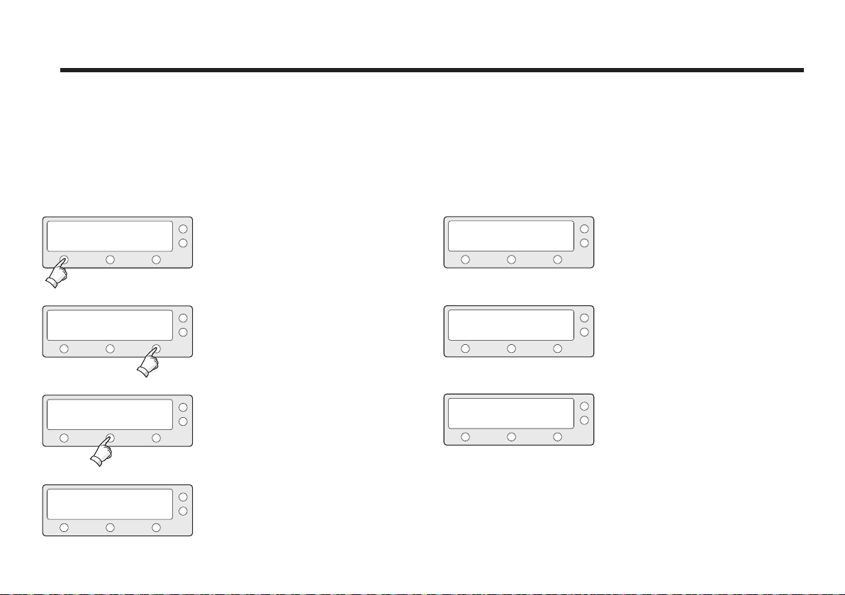
Display Versions
This sequence enables you to see what version of antenna
and ACU software are installed on your system.
SETUP MODE ?
YES
SET SAT PAIR ?
PREV
PREV
S/N: 0000000000
YES
VIEW VERSION ?
YES
B4-209A
NO
NEXT
NEXT
EXIT
1. Press YES to enter Setup Mode.
2. Press NEXT seven times to enter view
version mode.
X7
3. Press YES to view version.
4. Antenna product name and S/N are
shown.
Press EXIT to return to main setup
mode.
ANT S/W VER : 4.00
S/N: 0000000000
ACU S/W VER : 0.01
S/N: 0000000000
LIBRARY VER : 0.01
S/N: 0000000000
EXIT
EXIT
EXIT
5. Antenna software version and S/N are
shown.
Press EXIT to return to main setup
mode.
6. ACU software version and S/N are
shown.
Press EXIT to return to main setup
mode.
7. Library version and S/N are shown.
Press EXIT to return to main setup
mode.
45
Page 46
Raymarine Satellite TV Antenna Systems
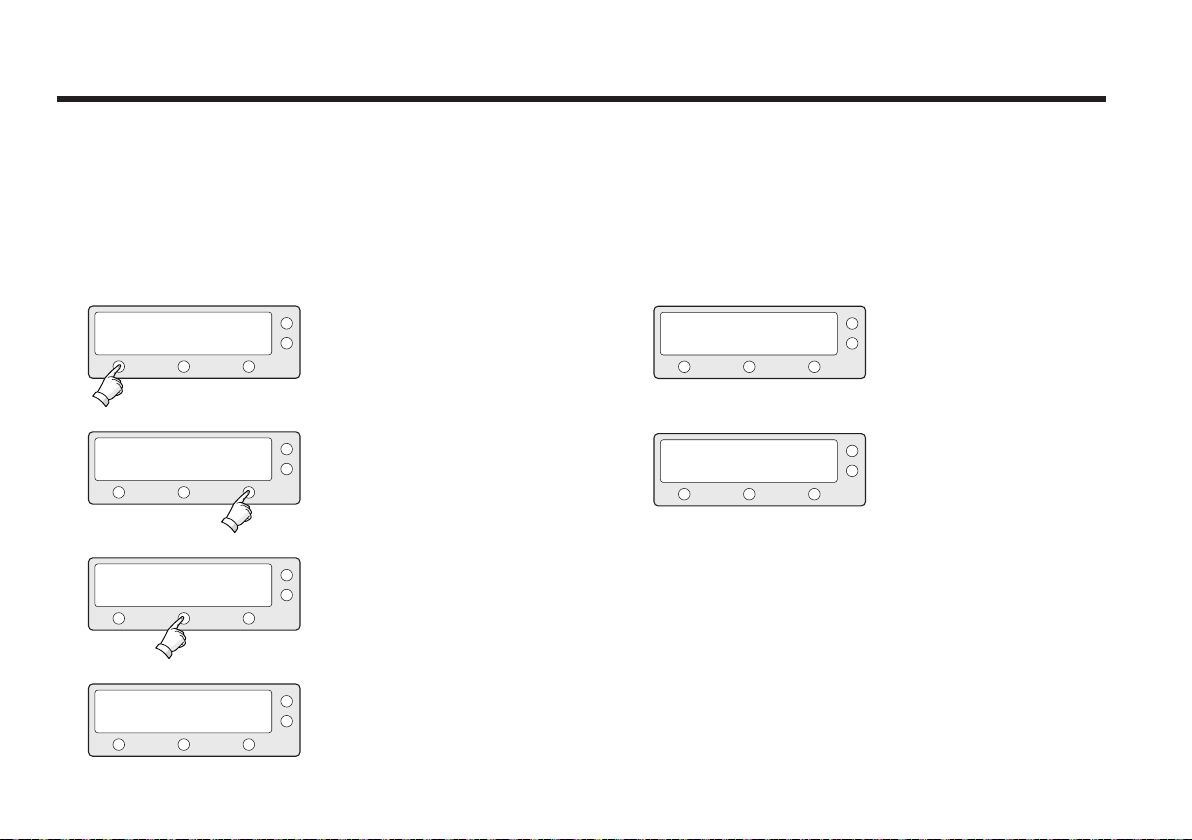
Display Power
SETUP MODE ?
YES
NO
1. Press YES to enter setup mode.
ANT POWER : 25.9 V
EXIT
5. Antenna input voltage is shown.
Press center soft key to view IRD Voltage and frequency.
Press EXIT to return to main setup
mode.
SET SAT PAIR ?
PREV
VIEW POWER ?
PREV
ACU POWER : 27.1V
YES
YES
NEXT
NEXT
EXIT
2. Press NEXT eight times to enter view
power
mode.
X8
3. Press YES to view power.
4. ACU input voltage is shown.
ACU output voltage is shown.
Press any key to return to main setup
IRD : 18V + ##kHz
EXIT
6. IRD voltage and frequency are shown.
Press EXIT to return to main setup
mode.
mode.
46
Page 47
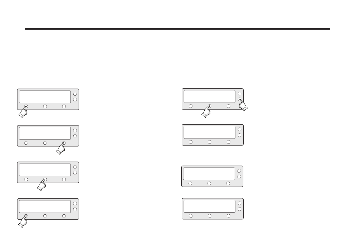
Setting Remote Control
SETUP MODE ?
YES
SET SAT PAIR ?
PREV
PREV
NEXT
YES
SET REMOCON ?
YES
FUNC : CHANGE SAT
SELECT
NO
NEXT
NEXT
EXIT
1. Press YES to enter setup mode.
2. Press NEXT nine times to enter
remote control setting mode .
X9
3. Press YES to set remote control.
4. Select the Function*
NEXT - Shows next function.
FUNC : SLEEP MODE
NEXT
SELECT
PRESS A REMOTE KEY
BACK
FAILED - TRY AGAIN
THAT KEY IS USING
EXIT
EXIT
5. SELECT/ENTER - Registers a key on
remote control.
6. Point remote control to ACU.
Press any key on remote control for
selected function and press the same
key again for confirmation. Press BACK
to move to previous screen.
Press EXIT to return to main setup
mode.
7. If failed to press the same key twice,
TRY AGAIN will be displayed.
8. If failed to register a free key, KEY IS
USING will be displayed.
47
Page 48
Raymarine Satellite TV Antenna Systems
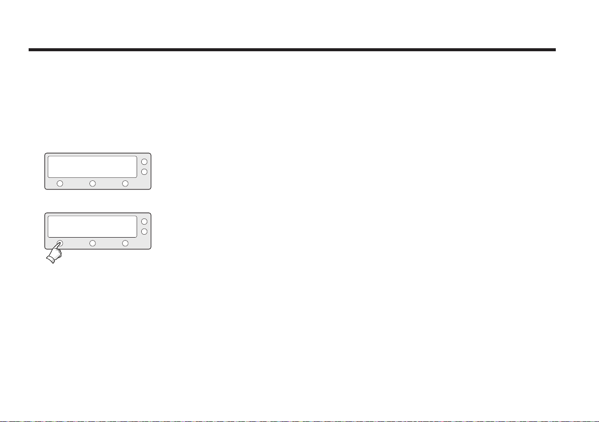
REMOTE KEY REGISTED
FUNC : CHANGE SAT
NEXT EXITSELECT
Function*
CHANGE SAT - Change the target satellite.
SLEEP MODE - Enter sleep mode.
CLEAR REGISTERED KEY - Clear registered key.
48
9. REMOTE KEY REGISTED will be
displayed if key has been properly
registered.
10. Press NEXT to shows next function.
Press EXIT to return to main setup
mode.
Page 49
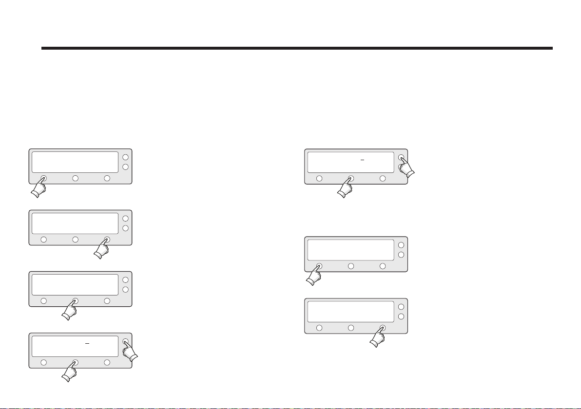
Setting Antenna Go Position
The antenna can be controlled manually by using the ACU.
SETUP MODE ?
YES
SET SAT PAIR ?
PREV
PREV
YES
ANT GO POSITION ?
YES
GO TO AZ : ##.#
-
INPUT
NO
NEXT
NEXT
+
1. Press YES to enter setup mode.
2. Press NEXT ten times to enter antenna
go position mode.
X10
3. Press YES to go position.
4. Input position value for azimuth (AZ) axis.
+ increases the value. - decreases the value.
Change the underscored digit using the +/- buttons.
Press INPUT to accept the value and move to next
digit.
Press BACK to move to previous digit.
Press ENTER to move to next screen.
GO TO EL : ##.#
-
INPUT
GO TO POSITION ?
YES
AZ:###.# EL:###.#
NO
EXIT
5. Input position value for elevation (EL)
+
axis.
+ increases the value. - decreases the
value.
Change the underscored digit using
the +/- buttons.
Press INPUT to accept the value and
move to next digit.
Press BACK to move to previous digit.
Press ENTER to move to next screen.
6. Press YES to move the antenna to
input position.
Press NO to return to the Antenna Go
Position mode.
7. Press EXIT to return to main setup
mode.
49
Page 50
Raymarine Satellite TV Antenna Systems
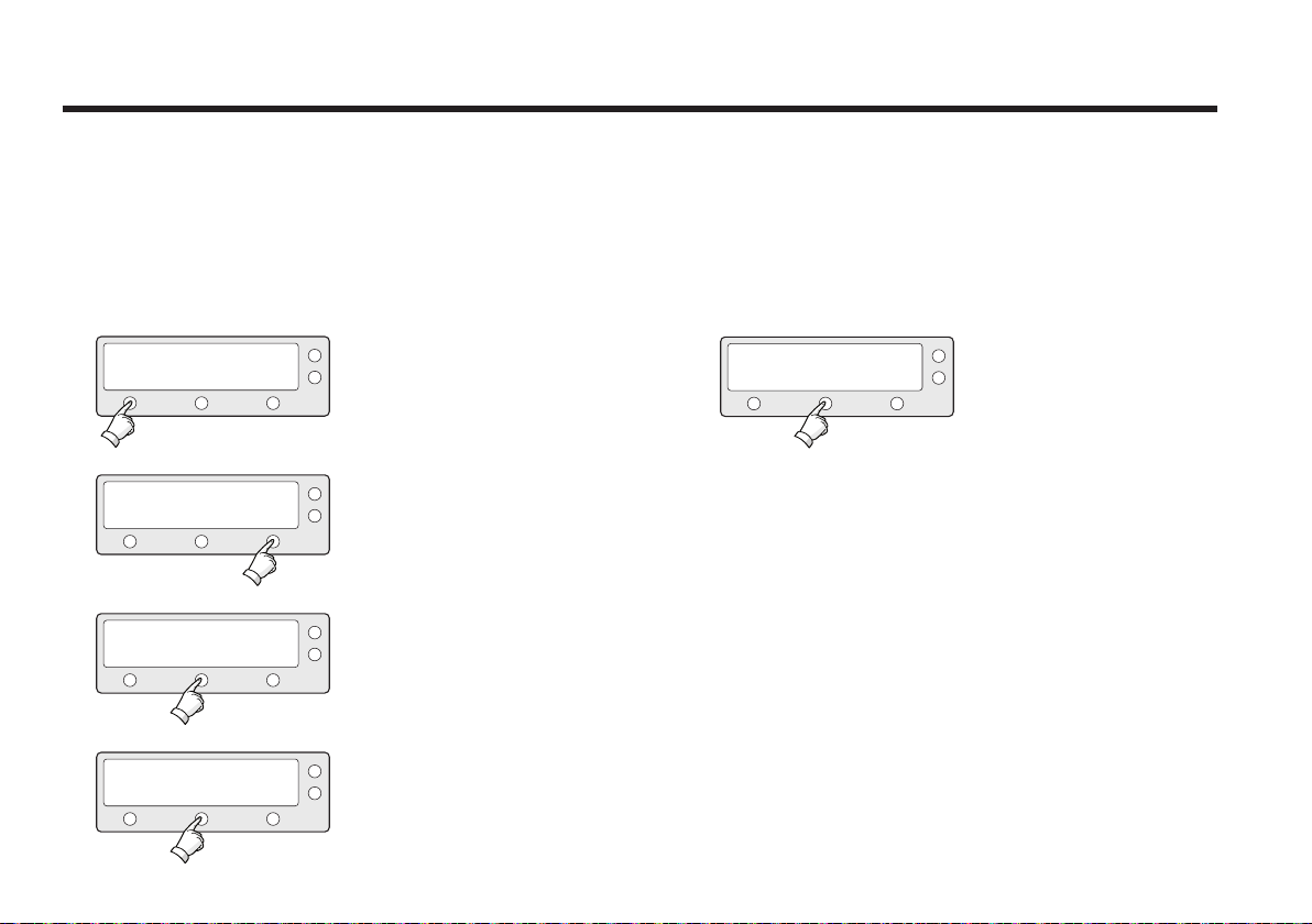
Setting the Antenna Move Step
The antenna can be moved by 1° step manually by using
ACU.
SETUP MODE ?
YES
NO
1. Press YES to enter setup mode.
STEP EL : ##.#
DOWN UPEXIT
5. Move the antenna in the EL axis.
UP - Move the antenna up.
DOWN - Move the antenna down.
EXIT - Return to antenna move step
mode.
2. Press NEXT eleven times to enter
antenna move step mode.
PREV
SET SAT PAIR ?
YES
NEXT
X11
ANT MOVE STEP ?
PREV
STEP AZ : ###.#
CCW
YES
EL
NEXT
CW
3. Press YES to move step.
4. Move the antenna in the AZ axis.
CW - Move the antenna clockwise.
CCW - Move the antenna counter
clockwise.
EL - Go to elevation control screen.
50
Page 51
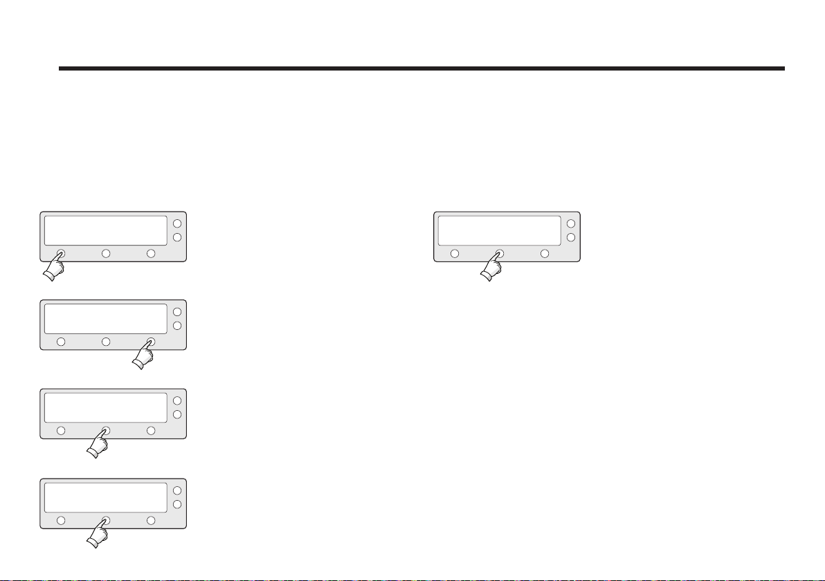
Executing Antenna Diagnosis
It is possible to see the antenna’s status by reviewing the results of diagnosis of the
antenna. Refer to the following codes to understand the diagnosis results.
SETUP MODE ?
YES
SET SAT PAIR ?
PREV
ANT DIAGNOSIS ?
PREV
CODE 101 TESTING
RESULT: ?
YES
YES
NO
NEXT
NEXT
EXIT
1. Press YES to enter setup mode.
2. Press NEXT twelve times to enter
antenna diagnosis mode.
X12
3. Press YES to diagnose the antenna.
4. CODE 101 is being tested.
Press EXIT to return to main setup
mode.
CODE 101 PASSED.
RESULT: ●
EXIT
5. CODE* 101 has passed.
Press EXIT to return to main setup
mode.
51
Page 52

Raymarine Satellite TV Antenna Systems
CODE*
52
CODE 101
CODE 102
CODE 103
CODE 104
CODE 105
CODE 106
CODE 107
Data communication between antenna and antenna control unit
is tested. If failed, check the RF cable.
AZ CW limit is tested.
If failed, check the limit sensors, motor and belt for AZ axis.
AZ CCW limit is tested.
If failed, check the limit sensors, motor and belt for AZ axis.
EL axis is tested.
If failed, check the limit sensors, motor and belt for EL axis.
Sub reflector is tested.
If failed, check the sub reflector.
LNB is tested.
If failed, check the LNB and control board.
Skew System is tested.
if failed, check the control board, skew motor, and skew sensor.
CODE 108
CODE 109
CODE 110
RESULT
STAT US
Antenna Input Power is tested.
If failed, check the RF cable.
ACU Power is tested.
If failed, check the ACU power cable and Input DC power.
IRD Power is tested.
If failed, check the ACU to the IRD cable and IRD power.
• Test is passed.
- Test is skipped.
? Test is under process.
Number refers to an error code
(••3••• -•••) 3 means error code 103.
Page 53
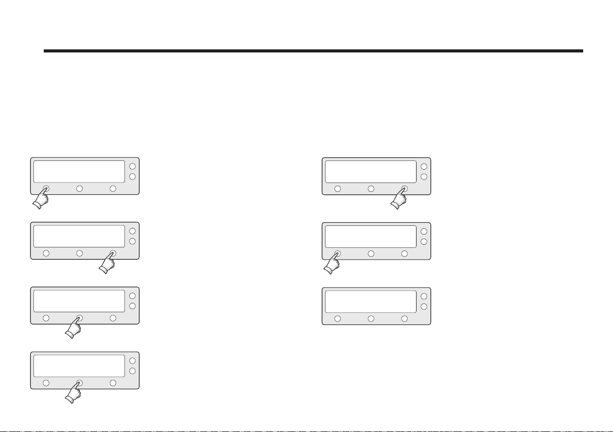
Setting Region
SETUP MODE ?
YES
SET SAT PAIR ?
PREV
PREV
CONTINENT : N_AMERICA
PREV
YES
LOAD REGION INFO ?
YES
SELECT
NO
NEXT
NEXT
NEXT
1. Press YES to enter setup mode.
2. Press NEXT thirteen times to enter
load region information mode.
X13
3. Press YES to load region information.
4. Select the Continent*.
PREV - Shows previous continent.
SELECT - Set the displayed continent.
NEXT - Shows next continent.
REGION : LOS_ANGELES
PREV
SELECT
NEXT
5. Select the Region*.
PREV - Shows previous region.
SELECT - Set the displayed region.
NEXT - Shows next region.
LOAD ?
YES
LOADING :
■ ■ ■ ■
DO NOT TURN OFF!
NO
6. Press YES to load region information.
Press NO to cancel and return to main
7. After loading, auto restart.
Continent*
N.AMERICA, S.AMERICA, EUROPE, ASIA.
Region*
NEW YORK, MIAMI, UK, JAPAN, and etc.
setup mode.
53
Page 54
Raymarine Satellite TV Antenna Systems
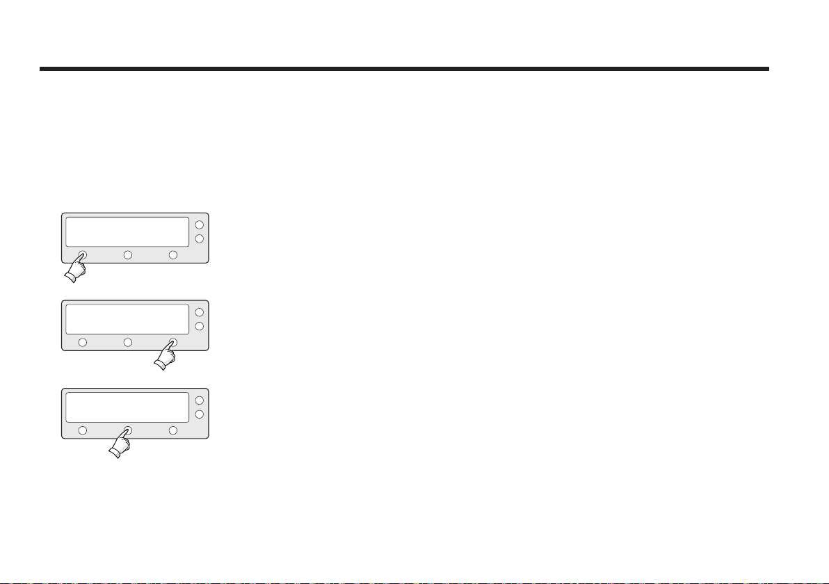
Setting the Factory Default Parameters
Initialize all of the antenna’s information to the factory’s default
setup.
1. Press YES to enter setup mode.
2. Press NEXT fourteen times to enter
default setting mode.
YES
PREV
SETUP MODE ?
SET SAT PAIR ?
YES
NO
NEXT
X14
SET DEFAULT ?
PREV
54
YES
NEXT
3. Press YES to set default parameters.
Page 55
ANTENNA CONTROL SOFTWARE
Introduction to Aptus
Aptus® is a next-generation graphical PC-based antenna
remote control software. The Aptus
and conveniently set up the antenna by using a personal
computer.
The minimum PC hardware and software requirements to
install and run Aptus® are as below.
Hardware
Hardware Requirements
CPU Intel
Memory 512MB or higher
DirectX9.0 or higher supported
Video Card
HDD 1GB or higher
Operating System and Software
Software Requirements
Operating System Windows XP (SP 2) or higher
Framework Microsoft.Net Framework 3.5 Service Pack 1 or
H/W acceleration supported
Video Memory 128MB or higher
higher
®
®
allows users to easily
®
Pentium® 4 or higher
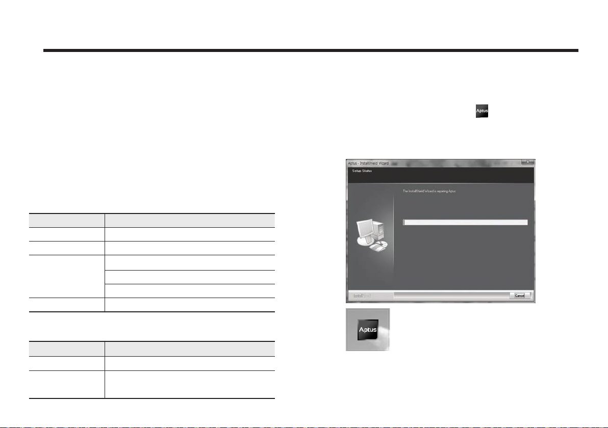
Software Installation
Double click the ‘Aptus Setup.exe’ icon to install Aptus
directly onto your computer/ laptop. The InstallShield Wizard
will guide you through the program setup process. The
installation routine provides an icon on the desktop.
Click the icon to start the software. In addition, Raymarine
also provides patch files for software upgrade.
®
55
Page 56
Raymarine Satellite TV Antenna Systems
PC to ACU Communication Setup
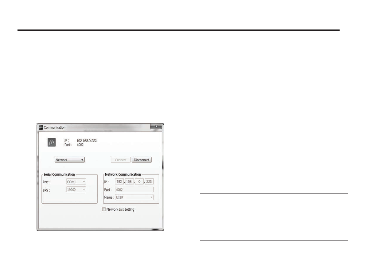
Starting Aptus
Double-click the Aptus® desktop icon, then Communication
Window appears to establish the data communication
between your PC and the ACU. Select options of connection
method to access your ACU either through the Serial Port
Communication or the Network Communication (TCP/IP).
®
Establish a data communication
Access ACU through Serial Communication
1. Connect a 9 pin Serial cable between the PC INTERFACE
connector on the ACU and the 9 pin Serial port on the PC.
2. Select Serial at communication type combo-box.
3. The baud rate of the ACU is 19200 for STV33.
4. Select a COM port which is not occupied by other devices.
5. Click the Connect button.
Access ACU through Network Communication (TCP/IP)
1. Connect your PC to the Ethernet Port or via Wi-Fi.(Turn o
the wireless connection while using the Ethernet port.)
2. Select Network at communication type combo-box.
3. Enter in the ACU’s IP address
(Factory default - Ethernet connection: 192.168.0.223 / Wi-Fi
connection : 192.168.1.223)
4. Enter in the ACU’s port number (Factory default : 4002)
Note: If the remote access PC is located in the same network
group with the ACU, the ACU can be accessed through the
internal IP address. But, if the remote access PC is located
outside of the network group, the ACU’s IP address should
be changed to the IP address assigned by the network
service provider.
56
Page 57
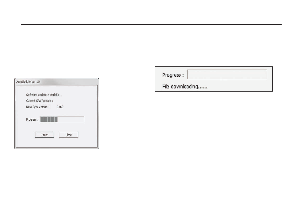
Auto Update
Aptus® checks and notifies the latest version when it
is started to maintain up to date software version by
AutoUpdate function.
®
1. When Aptus
software version from the server and runs AutoUpdate if new
version is available.
2. Current software version information is displayed.
3. It notifies new software version information.
4. When you click the “start” button, “File downloading…”
message is displayed while downloading files from the server.
is started, it automatically checks the latest
5. When file downloading is finished, “installing…” message is
displayed and Aptus patch runs and the installation starts via
InstallShield.
6. Click the “Finish” button when InstallShield installation is
finished, then “Run the Aptus” message is displayed and Aptus
runs and AutoUpdate is automatically finished.
57
Page 58
Raymarine Satellite TV Antenna Systems
Toolbar Menus
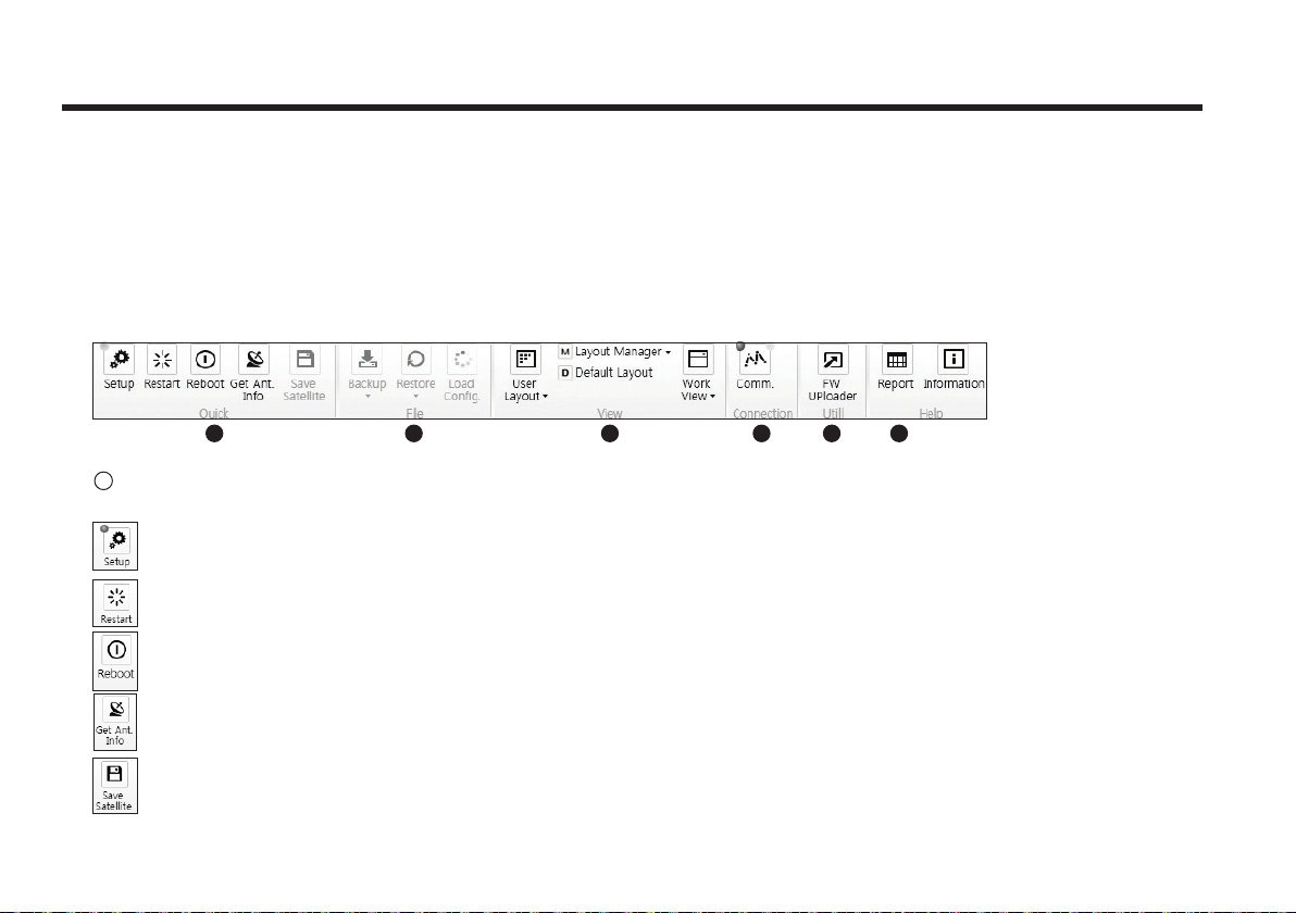
The toolbar menus at the top of the screen display command buttons of the most commonly used functions of the Aptus®. The toolbar
menus consists of 6 main menus; Quick (for quick launch of functions), File (not used on STV33), View(for user layout and work view),
Connection(for communication), Utill(not used on STV33) and Help(for reporting problems and information check) .
1 2 3 4 5 6
1
Quick
Setup: enters Setup mode.
Restart: exits Setup mode and restarts the antenna.
Reboot: reboots the antenna.
Get Ant. Info: obtains the information stored in the antenna
Save Satellite: Not used on STV33.
58
Page 59
2
File : Not used on STV33.
3
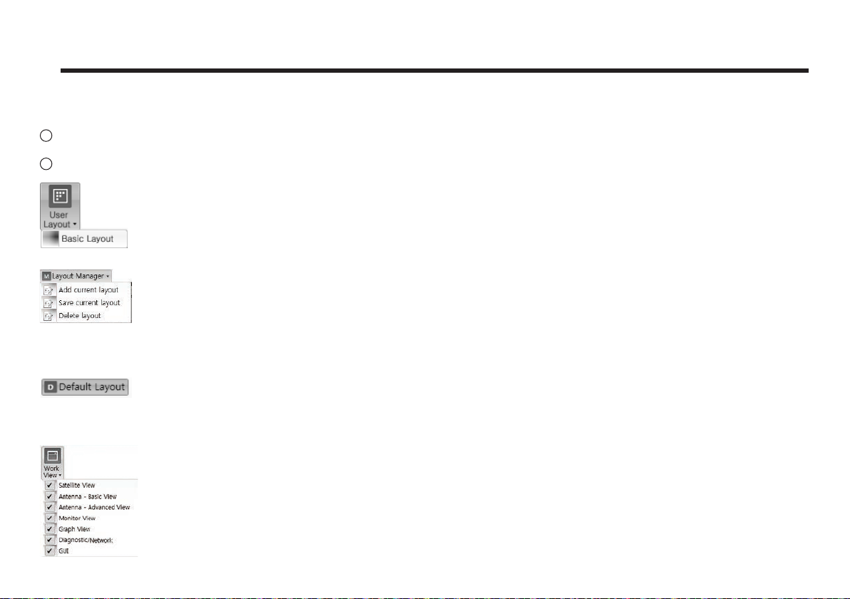
View
• User Layout: displays the layout list that the user has previously stored by using Layout Manager. If you select a layout in this list,
• Layout Manager: provides the user with add, delete, and save functionalities in order to manage the user’s layouts.
- Selecting ‘Add current layout’ opens a pop up window. Type in a desired name of current layout and click Add, then the new name
- When changes are made to the current layout, select ‘Save current layout’ option. The current layout will be saved with changes.
- To remove a layout, select ‘Delete layout’ option. Select a desired layout to remove on the pop up window, then click ‘Delete’. Close
• Default Layout: returns the current layout to the default layout.
• Work View: displays a list of seven pre-constructed Work View Tabs (Satellite View, Antenna Basic View, Antenna Advanced View,
the selected layout will be constructed in Work View screen. The ‘Basic layout’ is provided by default.
of the current layout will be saved to the list under User Layout menu.
the window by clicking on ‘Close’. The selected layout is removed from the User Layout list.
Monitor View, Graph View, ACU System View, and Antenna UI View) and also provides the Activate / Close functionalities for each
view tab. Activate the work view tab by ticking the checkbox next to it.
59
Page 60
Raymarine Satellite TV Antenna Systems
4
Connection
At any time, data communication channel can be re-established between Serial and Network connection.
Selecting Comm. Button will display Communication Window to connect to the ACU via Serial or Network communication.
5
Utill : Not used on STV33.
6
Help
• Report: provides e-mail contact to the technical support team to let the user report problems at any time.
• Information: displays the information of current Aptus
®
software version.
60
Page 61
System Property Status Dashboard
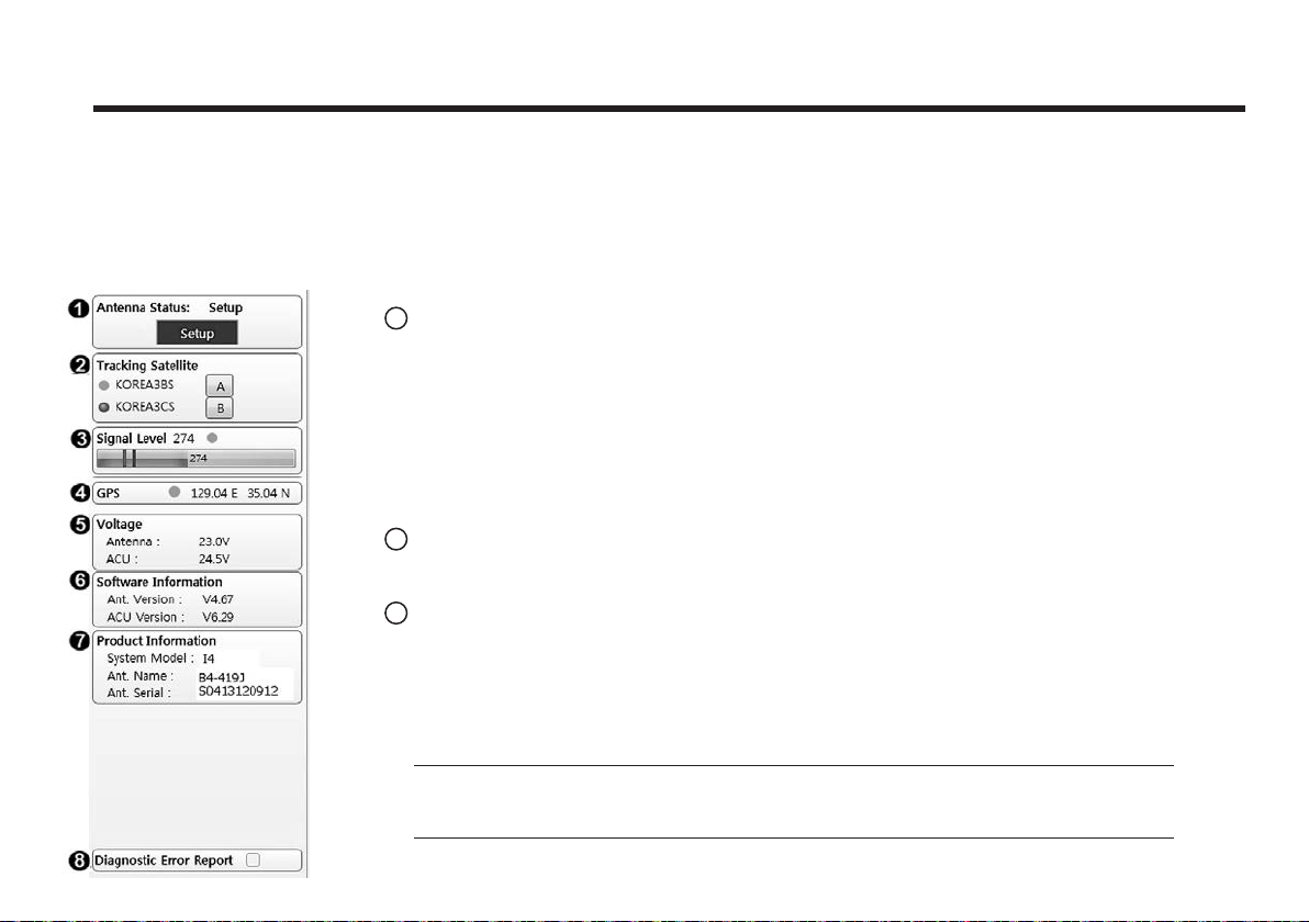
The property status dashboard on the left pane of the screen provides the antenna status, the availability of TX transmission, signal
level, GPS status, software information, product information and error status to be monitored quickly.
1
Antenna Status: Displays the status of the current mode of the antenna.
- Search: Antenna is searching the selected satellite.
- Tracking: Antenna is tracking the target satellite.
- Initialize: Antenna or ACU is initializing.
- Setup: Antenna is in SETUP mode.
- Sleep: Antenna is in Sleep mode.
- Unwrap: Antenna is unwinding/winding the cable in the antenna.
2
Tracking Satellite
Display/set current tracking satellite & tracking information. Up to 3 satellites can be selected.
3
Signal Level
The “Red” line indicates the signal “Detect Level Threshold” and the “Orange” line indicates
the signal “Tracking Level Threshold”. If the signal level is higher than the tracking level
threshold, the signal level bar will display “Blue” color. If the signal level is lower than the
tracking level threshold, the signal level bar will display “Orange” color and the antenna will
stay in searching mode.
Note: If the signal level is not higher than the tracking threshold, decrease the detect and
tracking level.
61
Page 62
Raymarine Satellite TV Antenna Systems
4
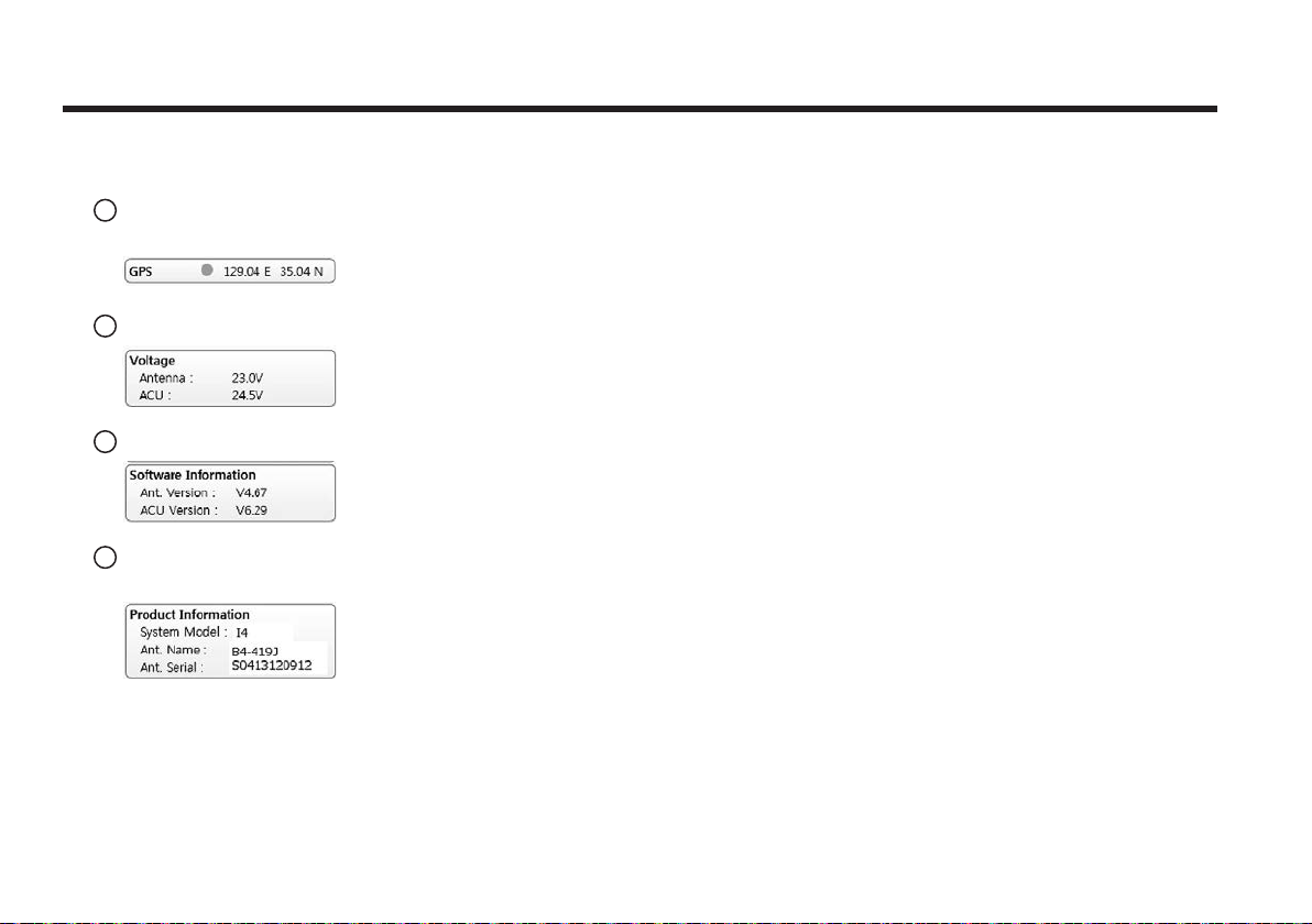
GPS: Displays the current GPS location from the Antenna information.
The status light flashes green if the system receives a correct input of the GPS.
5
Voltage: Displays the antenna and the ACU voltage information.
6
Software Information: Displays the antenna and the ACU firmware versions
7
Product Information: Displays the antenna and ACU serial numbers,
antenna model and ACU model.
62
Page 63
8
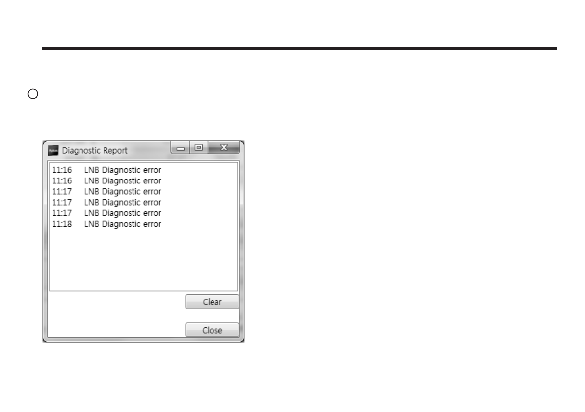
Diagnostic Error Report
The square button next to the Diagnostic Error Report turns red when the system receives an error.
Click the button to see a Diagnostic Report.
63
Page 64
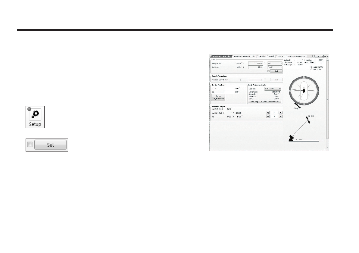
Raymarine Satellite TV Antenna Systems
Work View Tabs
Aptus® provides 7 Work View Tabs (Antenna Basic View, Antenna
Advanced View, Satellite ViewMonitor View, Graph View, Diagnostic
/Network View, and GUI View) to manage the Antenna and the
Satellite configuration.
How to modify the settings on Work View;
1. Enter the Setup mode by clicking Setup icon.
2. Tick the checkbox next to the “Set” button to modify the settings.
3. Enter the desired value then press the Set button to save the
settings.
1. Antenna – Basic Info.
This view tab provides information on the Antenna’s Current GPS
location, Skew Information, and the Antenna’s Angle. This view tab
uses the Antenna’s AZ and EL information in order to provide a
dynamic graphic user interface (UI).
64
- GPS: displays and sets current antenna’s GPS.
- Bow Information: not used on STV33.
- Go to Position : The current position (angle) of the antenna is
displayed.
Push the “Go to Target Position” button after keying in the
desired angle to move the antenna to target position.
- Find Antenna Angle: displays and sets the current antenna
angle. Select a desired satellite from the drop-down menu, then
longitude, azimuth, elevation and skew information are displayed.
angles and skew angle in relation to the longitude (orbit position)
of the antenna’s current GPS.
• Find Angles & Skew Antenna GPS: finds the current antenna
Page 65
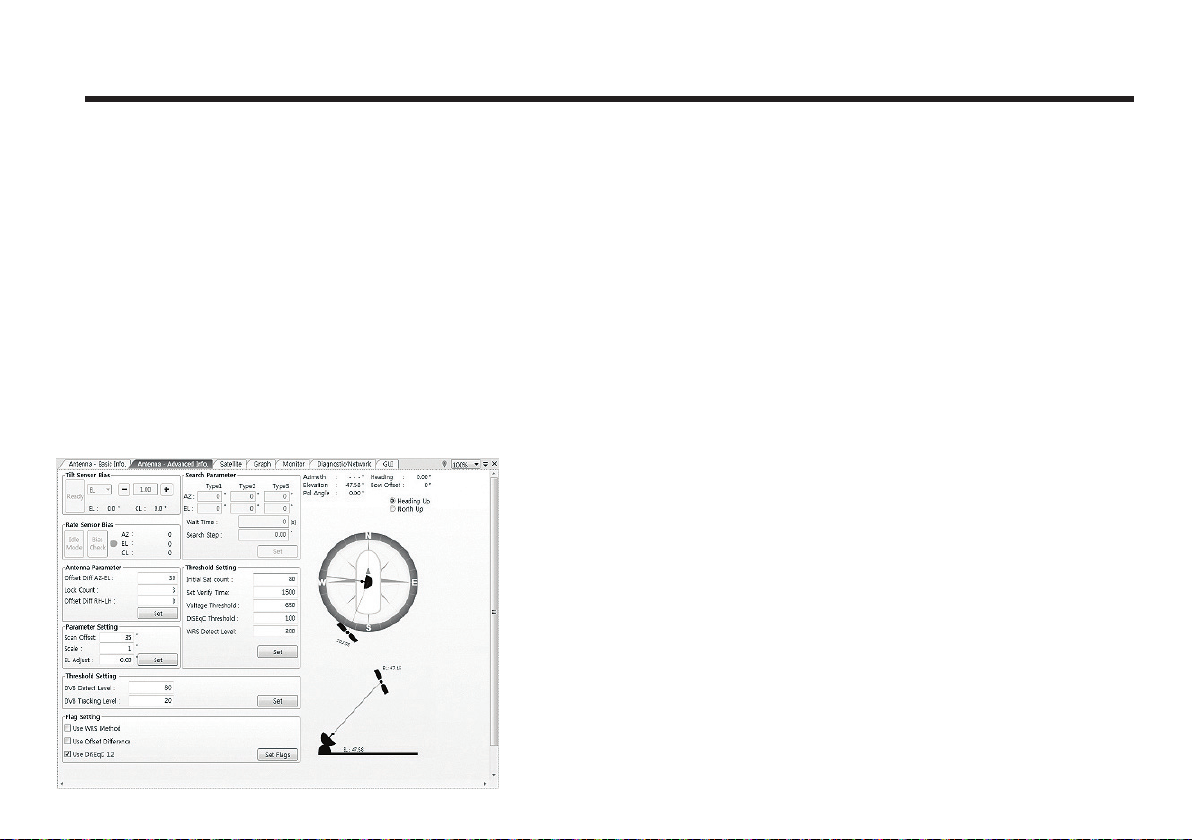
- Antenna Angle: displays and sets current antenna’s
absolute and relative AZ (azimuth) position, EL (elevation)
position and polarization (between Linear and Circular). You
can move antenna azimuth and elevation position and LNB
Pol angle by using the arrows or inputting a value to find the
desired satellite manually.
2. Antenna – Advanced Info.
This view provides information on Parameter Setting,
Threshold Setting, and Flag Setting.
-Tilt Sensor Bias: not used on STV33.
- Rate Sensor: not used on STV33.
- Antenna Parameter: used to set the antenna parameter
settings.
• Oset Di AZ-EL: The oset AZ-EL is to oset the angle
dierence between Azimuth and Elevation.
• Lock Count: The Lock Count is to set the number of
checking signal lock.
• Oset Di RH-LH: The oset RH-LH is to oset the signal
dierence between RHCP and LHCP.
- Parameter Setting: used to set the control parameter
settings.
• Scan Oset: The scan oset is to oset the angle dierence
between the black marker on the sub-reflector and the
optical sensor.
• Scale: The scale is to control the tracking speed while
antenna is tracking the satellite.
• EL Adjust: The elevation adjustment is to oset the angle
dierence between the mechanical elevation angle and
actual elevation angle.
- Threshold Setting: set the threshold level for detecting and
tracking the satellite signal.
• DVB Detect Level: displays and sets signal detection
threshold level when DVB tracking mode is in use.
• DVB Tracking Level: displays and sets signal.
65
Page 66
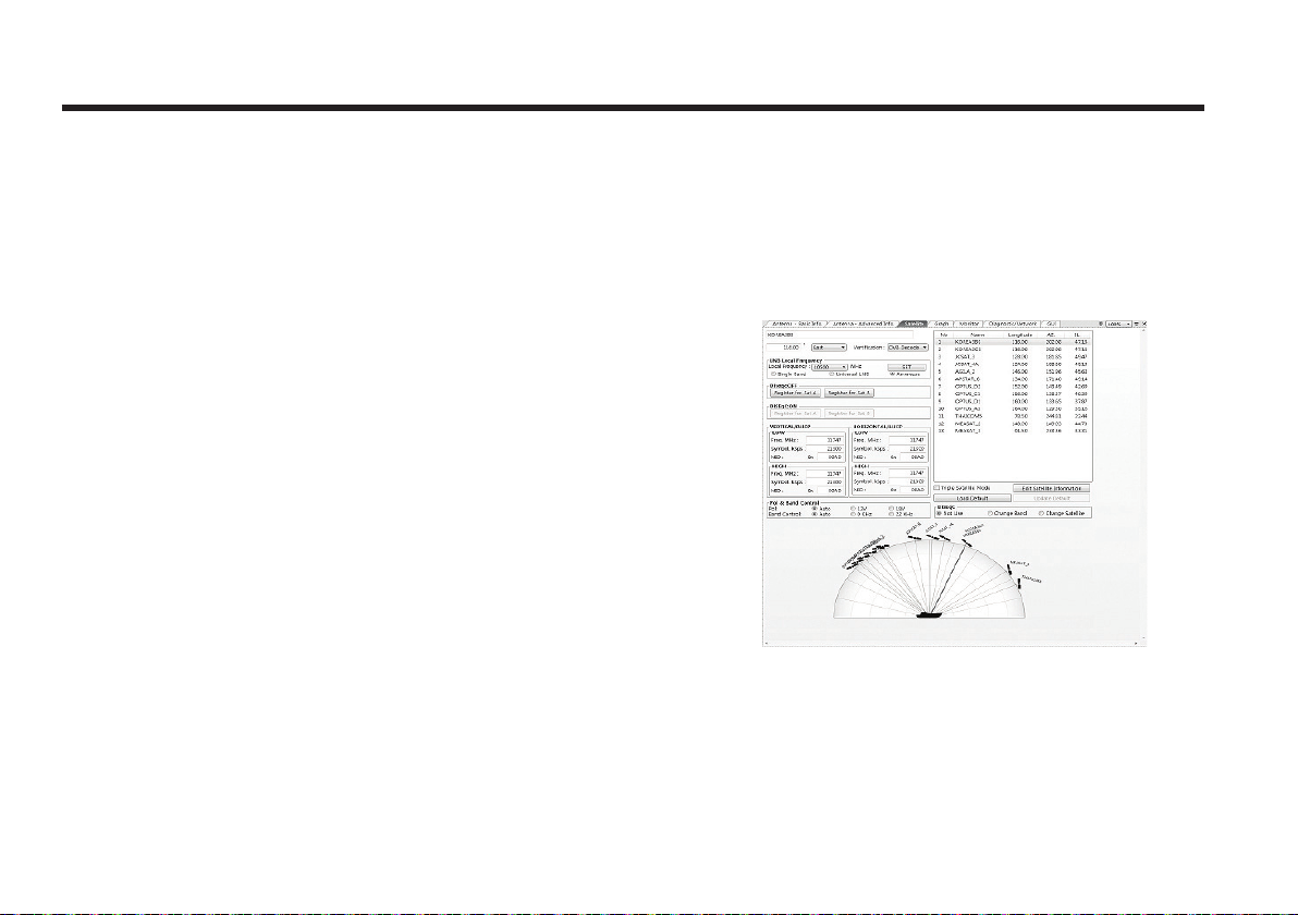
Raymarine Satellite TV Antenna Systems
- Threshold Setting
• Initial Sat Count: Set the threshold count for maintaining
tracking.
• Set Verify Time: Set the time of verifying whether the signal
detected is the signal of target satellite.
• Voltage Threshold: Set the voltage threshold. The voltage
threshold is to distinguish the voltage between 13V and 18V.
• DiSEqC Threshold: Set the DiSEqC threshold. The DiSEqC
threshold is to distinguish the 0KHz tone and 22KHz tone.
• WRS Detect Level: Set the WRS detection level.
- Flag Setting
• Use WRS Method: Use WRS method is to determine
whether the system uses “WRS Detect Level” or not. Use
WRS method and “WRS Detect Level” are pair functions.
• Use Oset Dierence: Use oset dierence is to determine
whether the system uses “Oset Dierence” or not. Use
Oset Dierence and “Oset Dierence” are pair functions.
• Use DiSEqC 1.2: Use DiSEqC 1.2 is to determine whether
the system uses the “DiSEqC 1.2” protocol or not.
3. Satellite (Satellite View)
The name, longitude, verification method of the satellite and
LNB local frequency are displayed.
- LNB Local Frequency: Displays or sets LNB local frequency
and its corresponding LNB voltage supplied. You may select
pre-programmed LNB LO settings from the drop down list..
66
Page 67
- Dual Satellite Mode/ Triple Satellite Mode: Registers the
target satellite.
• Pushing ‘Register for Sat A’ or ‘Register for Sat B’ button
after selecting the satellite in the list box makes it possible to
register A or B in Dual Satellite Mode.
• Pushing ‘Register for Sat A’ or ‘Register for Sat B’ or
‘Register for Sat C’ button after selecting the satellite in the
list box makes it possible to register A or B or C in the Triple
Satellite Mode.
• Transponder information consists of frequency, symbol and
NID (Network ID) of a transponder in tracking the satellite.
There are four groups of transponder information. ‘Vertical/
RHCP’ is applied when the IRD supplies 13V, and ‘Horizontal/
LHCP’ is applied when the IRD supplies 18V. ‘LOW’ is applied
when DiSEqC signal is not detected from IRD. ‘HIGH’ is
applied when the DiSEqC signal is detected from the
IRD. After modifying information, press the ‘Edit Satellite
Information’ button, then new information is updated in the
antenna.
- Pol & Band Control: The “Pol” controls 13V (Vertical/RHCP
band) or 18V (Horizontal/ LHCP band). The “Band” controls
DiSEqC 0KHz tone (Low band) and 22KHz tone (High band).
After modifying information, press ‘Edit Satellite Information’
button, then new information is updated in the antenna.
- Triple Satellite Mode: To select between Dual-Sat mode and
Triple-Sat mode, tick the ‘Triple Satellite Mode’ box at the
bottom of the screen.
- Edit Satellite Information: push the “Edit Satellite
Information” button to update the information after modifying
values.
- Load Default: Push the “Load Default” button to select a
regional library file *.rif according to your region.
- Update Default: After loading a regional library file *.rif, push
the “Update Default” button to update the system.
- Diseqc: When the operation method of DiSEqC is selected
to “Change Band”, DiSEqC may be used for updating the
local frequency and to “Change Satellite”, for updating the
target satellite.
67
Page 68
Raymarine Satellite TV Antenna Systems
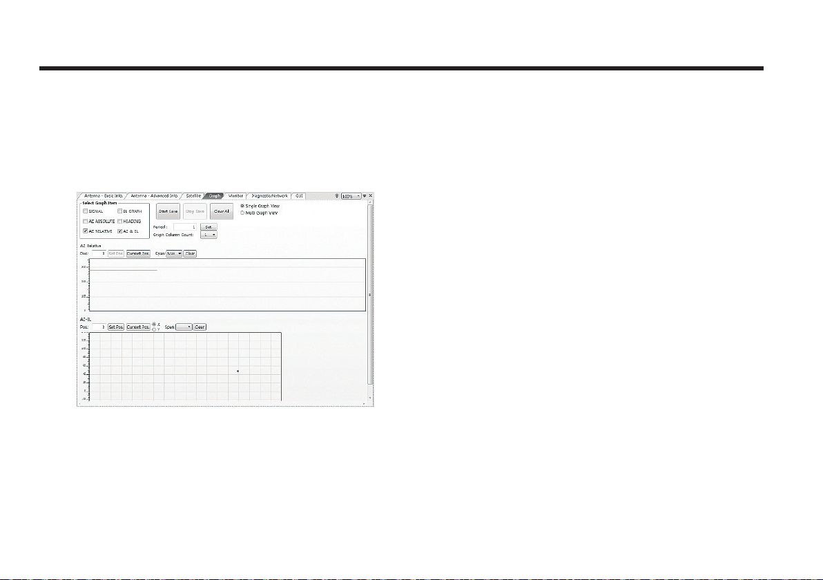
4. Graph
This view provides information on Signal, Elevation (EL),
Absolute AZ (Azimuth), Relative AZ, Heading, AZ and EL in
Single or Multi graph formats.
- Select Graph Item: shows the graphs of only the checked
item(s) in a Single or Multi Graph View.
- Single Graph View: shows Graph Views per each single
Graph Item selected in ‘Select Graph Item’.
- Multi Graph View: shows one large integrated Graph View
of multiple Graph Items selected in ‘Select Graph Item’.
- Start/Stop Save: the chosen item is saved within the data
log. The data log which stores the information displayed in
the graphs can be later used for a service technician to find
out a cause of any possible problem to the antenna.
- Clear All: clears everything drawn on the Graph View
window.
- Set Pos.: sets the current position as center value of each
Graph Item.
- Current Pos.: moves to the location according to values of
each Graph Item.
- Span: sets the Display Range(s) of each corresponding
Graph Item.
- Period: displays and sets the signal sampling rate.
- Graph Column Count: makes all Graph Views show in either
one or two-column format.
68
Page 69
5. Monitor
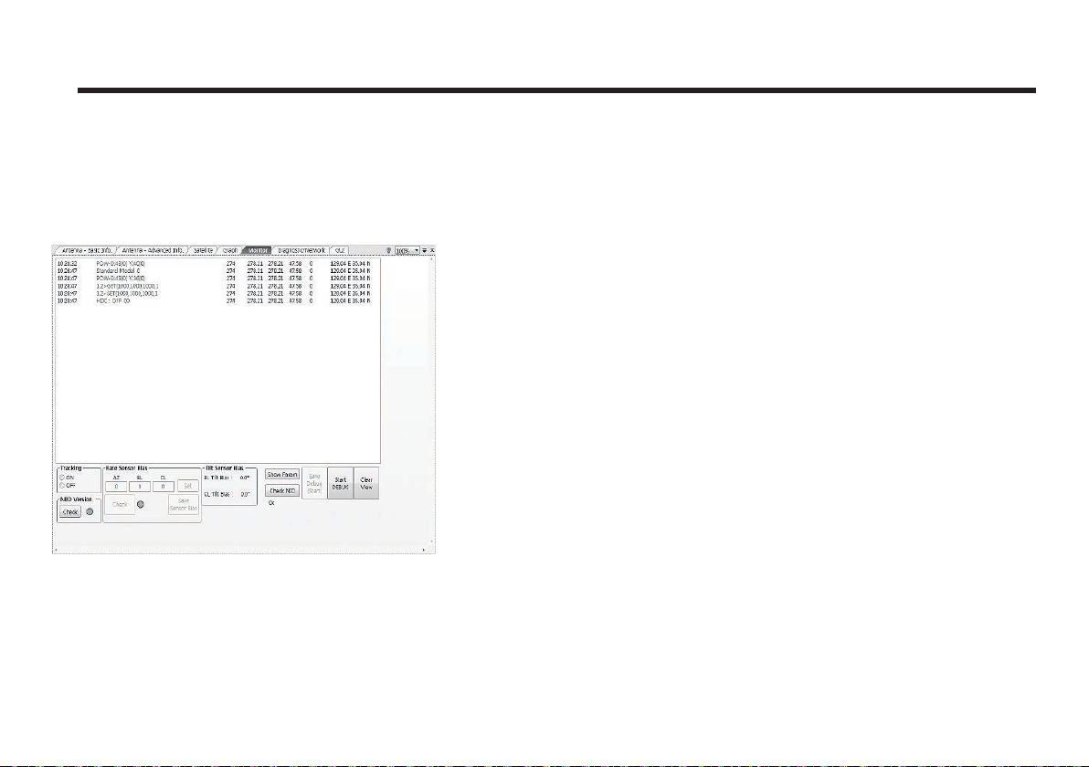
This view provides a UI which can monitor all data that has
been received from the ACU.
- Tracking: not used on STV33.
- Rate Sensor Bias: not used on STV33.
- Tilt Sensor Bias: not used on STV33.
- Show Param: shows the current antenna parameters.
- Check NID: verifies the NID (network ID) of the current
tracking transponder. Press the NID button to obtain the NID
only if the antenna is locked onto the desired satellite.
- Start Debug: starts the debug log of the antenna. The
debug message will be displayed once the debug button is
pressed.
- Stop Debug: stops debug logging of the antenna.
- Save Debug (Start/Stop): starts or stops saving the debug
log. This button is enabled once the Start Debug button is
pressed.
- Clear View: clears the debug message or log data in
monitoring window.
69
Page 70
Raymarine Satellite TV Antenna Systems
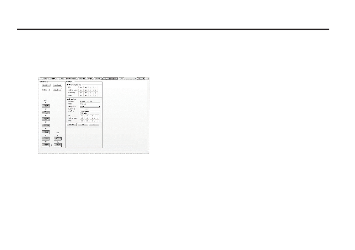
6. Diagnostic / Network
This view provides Antenna Diagnostic Testing and Network
Settings.
- Diagnostic : select to run a full diagnostic test or single
diagnostic test.
“Green” indicator is displayed for the test under progress.
“Blue” indicates the test result as Pass while “Red” indicates
the result as Fail.
“Yellow” indicates the test has been skipped.
• Serial Comm.: tests the data communication
between the antenna and the ACU.
• AZ Limit (CW) : tests the azimuth limit (CW)
• AZ Limit(CCW) : tests the azimuth limit(CCW)
• EL Limit: tests the elevation limit.•
• Sub-Reflector: tests the Sub-Reflector.
• LNB: tests the LNB.
• Power (Ant.): tests the antenna power to see
whether or not it is within the nominal operating
range.
• Power (ACU): tests the ACU power to see whether
or not it is within the nominal operating range.
• Receiver Connection: tests the data communication
between the antenna and the receiver.
70
Page 71
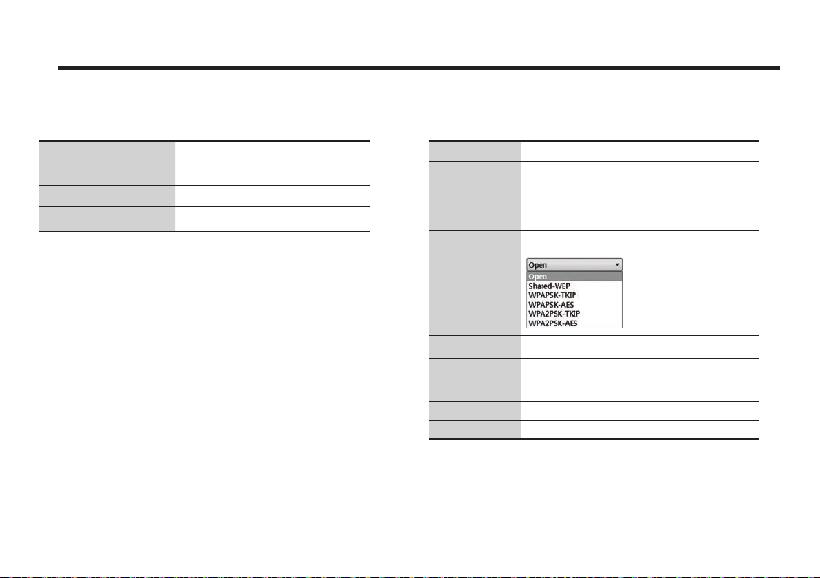
• Network Setting:
IP the network IP address.
Subnet Mask the network subnet mask.
Gate Way the gateway for network.
DNS the DNS address.
• Wifi Setting:
Power select to turn on or o Wifi network function.
SSID the SSID is the network name shared among all devices in a
Encryption The following dierent types of encryption are supported:
Password the password should be 8 alphanumeric characters.
Confirm enter the password again to confirm it.
IP the current wireless IP address.
Subnet the current wireless subnet mask.
DNS the current default wireless DNS address.
wireless network. The SSID must be identical for all devices in
the wireless network. It is case-sensitive and must not exceed
8 alphanumeric characters, which may be any keyboard
character. Make sure this setting is the same for all devices in
your wireless network.
• Default: initializes the network and Wi-Fi settings.
Note: When the setting is changed, it needs to be re-connected with
the modified IP address.
71
Page 72
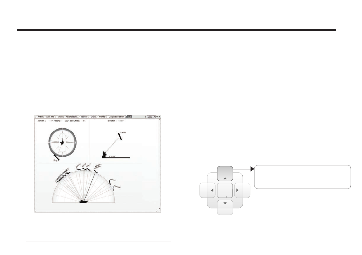
Raymarine Satellite TV Antenna Systems
7. GUI
This view shows a graphical representation of the current
antenna position which allows you to easily identify whether
or not the antenna is aligned properly to the target satellite
or is in a block zone. In addition, this view shows the current
satellite that the antenna is pointed towards and the satellites
that are located at a 180°arc on the horizon, according to the
current position.
Note: Based on the satellite EIRP footprint and the size of the
antenna, you may not be able to track all the satellites visible
in 180° arc.
72
8. Work View Functions
The seven Work View Tabs displayed in the Work View can
be arranged in customized layouts.
- Layout Formatting
• Each of the Work View Tab can be separated from the rest
Tabs. Click and hold the left mouse button on the Work View
Tab’s header and then drag a desired Tab out. When a Work
View Tab is separated from the rest of your Work View Tabs,
again click and hold the left mouse button on the Work View
Tab’s header to display a cross-shaped Navigator icon. While
holding the mouse button, bring the selected Work View Tab
closer to the Navigator icon and release the mouse button
at your desired position (top, left, right or bottom arrow). This
time, the selected Tab will be moved to the desired position.
Move the selected Work View Tab
to the top position of the Work View
layout.
Page 73
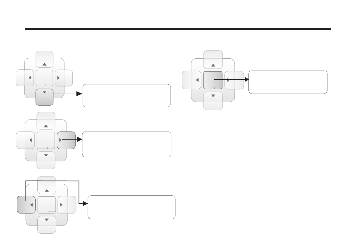
Move the selected Work View Tab
to the bottom position of the
Work View layout.
Move the selected Work View
Tab to the center position of
the Work View layout.
- Horizontal or Vertical Tab Group
Move the selected Work View Tab
to the right position of the
Work View layout.
Move the selected Work View Tab
to the left position of the
Work View layout.
The Work View Tabs can be also aligned horizontally or
vertically. Without dragging them out, right-click the mouse
button on a desired Tab header and select ‘New Horizontal
Tab Group’ or ‘New Vertical Tab Group’ option. Selecting
‘New Horizontal Tab Group’ will separate a selected Tab from
the rest of other Tabs then arrange it in a horizontal format.
Likewise, selecting ‘New Vertical Tab Group’ will separate a
selected Tab from the rest of other Tabs then arrange it in a
vertical format.
- Closing the Work View Tab
To close the Work View Tab, right-click the mouse button on
a desired Tab header and select ‘Close’ option in the drop
down list. To close all Work View Tabs except the selected
Tab, select ‘Close All But This’ option in the drop down list.
73
Page 74
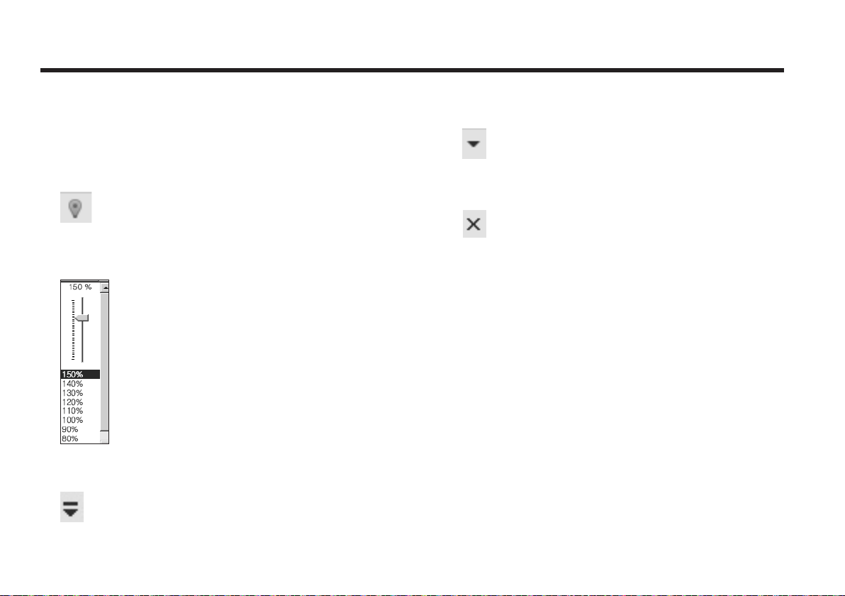
Raymarine Satellite TV Antenna Systems
- Zoom Tool
Using the Zoom tool, you can easily select the magnification
you want by using Zoom In and Zoom Out bar, and Fit in
Work View button.
View Name Button: displays the current Work View name.
Fit Work View Button: fits the current view to the Work View
window size. The button toggles between the fit view and
the previous view.
Zoom In and Zoom Out Bar: zooms in and out to expand and
reduce the View to the desired size. (The zoom changes in
10% increments.)
View Switch Button: displays a list of the current views in a
list. Choosing one of these views will display the selected
view in the Work View window.
74
Close View Button: closes the current view.
Page 75
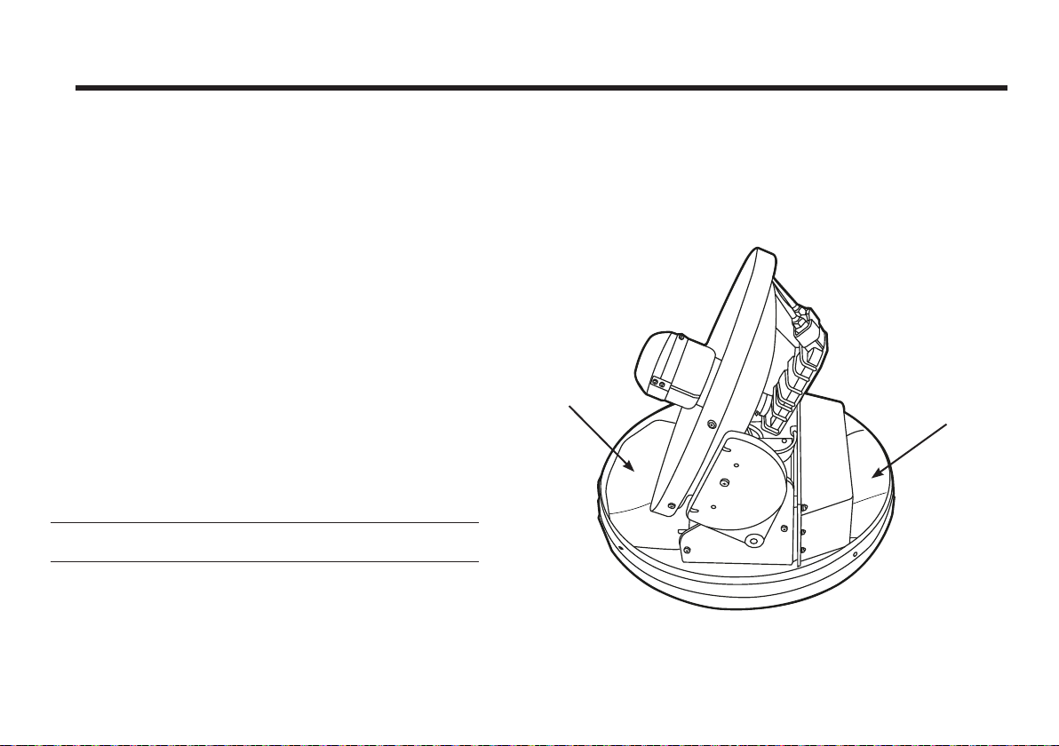
Preparation for Transportation
This is to describe how to prepare the antenna internally for transportation.
The following procedures to secure the antenna shall be strictly observed to protect it from being damaged
during transportation.
1. Refer to the drawing on the right.
2. Rotate antenna left and right slowly untill the limit switch is
pressed.
3. Turn the antenna by 360° to the reverse direction.
4. Insert the shipping foams in front of the dish and back side of the
pedestal to secure the pedestal in position with the bottom radome.
5. Cover upper part of radome being careful for it’s not touching the
reflector, and then assemble upper part of radome.
6. Pack Raymarine STV33 into the original package box.
Note: Don’t rotate it quickly, or you may damage the antenna limit
system.
Shipping Foam
Shipping Foam
Figure 26 : Preparation for Transportation
75
Page 76

Raymarine Satellite TV Antenna Systems
Warranty
To register your Raymarine product ownership, please
visit www.raymarine.com/warranty and register online. It
is important that you register your product to receive full
warranty benefits. Your unit package includes a bar code
label indicating the serial number of the unit. You will need
this serial number when registering your product online. You
should retain the label for future reference.
76
Page 77

Appendix : STV33 Technical Specification
General
Approvals
CE – conforms to
FCC – verified to
Dimensions
Satellite antenna unit
Antenna dish diameter
Antenna control unit
Weight
Satellite antenna unit
Antenna control unit
Environmental
Operating temperature range
Storage temperature range
Humidity limit
Operating voltage 9 ~ 30V D C
Power consumption Typ. 30W, Max. 50W
EU Directive 89/336/EEC
CFR47:Part 15
37cm (14.6”) x 38cm(15”)
33cm(13.3”)
17.8cm(7”)x21.7cm(8.5”)x5.4cm(2.1”)
4.5kg (9.5 lbs)
1.2kg (2.6 lbs)
-25°C to +55°C (-13°F to +131°F)
-40°C to + 80°C (-40°F to + 176°F)
95% R.H
Antenna system performance
Frequency Ku-band (10.7 to 12.75 GHz)
Minimum EIRP 51 dBW
Azimuth range 680°
Elevation range +10° ~ +80°
Ship’s motion
Roll and pitch
response rate
Turn rate 60° per second
Roll ±25°
Pitch ±15°
60° per second
77
Page 78

Owner notes:
Page 79

Owner notes:
Page 80
Marine House, Cartwright Drive, Fareham, Hampshire.
Raymarine
PO15 5RJ. United Kingdom.
Tel: +44 (0)1329 246 700
www.raymarine.com
a brand by
 Loading...