

Page 1

SmartPilot
X-Series
Commissioning &
Setup Guide (SeaT alk)
for SPX-10, SPX -30,
SPX-SOL & SPX-CAN
Systems
Document reference: 81307-1
Date: Dec ember 20 07
Page 2

Raymarine, SeaTalkng, SmartPilot, AutoLearn, AutoRelease, AutoTack, AutoTrim, GyroPlus and WindTrim are trademarks of
SeaTalk is a registered trademark of Raymarine Ltd.
Raymarine Ltd
© Handbook contents copyright Raymarine plc
Page 3

Contents i
Contents
Preface ...........................................................................................................................iii
Safety notices ..........................................................................................................iii
EMC Conformance ..................................................................................................iii
Warranty ...................................................................................................... ............iii
Pressure washing ....................................................................................................iii
Product documents ..................................................................................................iv
Product disposal ......................................................................................................iv
Chapter 1:Procedures ...............................................................................................1
1.1 Applicability ................................................................................................... 1
Requirement................................................................................................... 1
SPX-CAN systems......................................................................................1
Rudder reference in formation.............. ............................ ............................ ... 2
SeaTalk Controller diffe rences.. ............................ ............................ ..............2
1.2Commissioning procedure s ....................................... ............................ ........ 3
Dockside prep aration...................... ................................. ...............................3
Step 1 - Switching on..................................................................................3
Step 2 - Checking SeaTalk and NMEA connections ..................................4
Step 3 - Checking rudder bar and steering operating sense ...................... 5
Step 4 - Dealer calibration settings.............................................................6
Finishing dockside preparation................................................................. 10
Seatrial calibrati on.......................... ................................. .............................10
Getting started.......................................................................................... 10
Swinging the compass..............................................................................11
Aligning compass heading........................................................................12
Aligning rudder bar ................................................................................... 13
AutoLearn................................................................................................. 14
Commissioning co mplete..................................... .................................. ...... 16
1.3Manual set-up ......... ............................ ............................ ....................... ...... 16
Requirement................................................................................................. 16
Checking SPX system operation.............................................................. 16
Adjustable parameters..............................................................................17
Setting response level .............................................................................. 17
Rudder gain.. ............................ ............................ ............................ ............ 17
Checking................................................................................................... 17
Adjusting................................................................................................... 18
Counter rudder ... ............................ ............................ ............................ ...... 18
Checking................................................................................................... 18
Adjusting................................................................................................... 18
AutoTrim....................................................................................................... 19
Adjusting................................................................................................... 19
Rudder dampin g....................... ............................ ............................ ............ 19
Chapter 2:SPX system settings ........................................................................... 21
2.1Introduction ........ ........... ........... ........... ........... ............ ........... ...... ........... ......21
Calibration modes .......................................... .................................. ............ 21
Display calibration..................................................................................... 21
User calibration........................................... ........................................ ...... 21
Seatrial calibration.................................................................................... 21
Dealer calibration......................................................................................21
Accessing t he Calibration mode s................................ ............................ ...... 22
Adjusting calib ration values....................... .................................. .................22
Page 4

ii SmartPilot X-Series Commissioning & Setup Guide
2.2Display calibration ................................... ............................ .........................23
RUDD BAR screen............................ ............................ ............................ ...23
HDG screen............................................. ............................ .........................23
Data pages ................................. .................................. ...............................23
Setting up data pages...............................................................................24
2.3User calibration ............................................ .................................. ..............25
AutoT ac k (sail boat only).............. .................................. ...............................26
Setting default AutoTack angle.................................................................26
Selecting Relativ e Tack............................ ...... ..... ...... ...............................26
Gybe inhibit (sail boat only )................................. ............................ ..............26
Wind selection (sail boat only) ...................... ............................ ....................26
WindT rim (sail boat on ly) ......................... ............................ .........................27
Response level................. ............................ ....................... .........................27
2.4Dealer calibration .................................... ...................... ............................ ... 27
Seatrial calibrati on lock ........................................... .................................. ... 28
V essel type ............................................. ............................ ...................... ...28
Drive type .................... ............................ ...................... ............................ ... 29
Align rudder....................................... ............................ ............................ ...29
Rudder limit ................. ............................ ............................ .........................30
Rudder gain ...................................... ............................ ............................ ... 30
Counter rudder........................................ ...................... ............................ ...30
Rudder damping.... ............................ ............................ ............................ ... 30
AutoTrim ......................................................................................................30
Response level ................................. ............................ ............................ ... 31
Turn r ate limit............... ............................ ............................ ...................... ... 31
Off course angle ................................ ............................ ............................ ...31
AutoTack ......................................................................................................32
Gybe inhibit............ .................................. ................................. ....................32
Wind selection............................. ............................ ............................. ........32
WindTrim......................................................................................................32
Power S teer............................ ............................ ............................ ..............32
Cruise speed..................................... ............................ ............................ ... 33
Latitude ........................................................................................................ 33
System reset.......... ............................ ............................ ....................... ........33
2.5System defaults ........................................... ............................ ....................35
SmartPilot X-Series Specifications.....................................................................37
Glossary....................................................................................................................... 39
Index..............................................................................................................................41
Page 5
Preface iii
Contents
Preface
Safety notices
WARNING: Product installation & operation
This equipment must be installed, commissioned and operated
in accordance with the Raymarine instructions provided.
Failure to do so could result in personal injury, damage to y our
boat and/or poor product performance.
WARNING: Electrical safety
Make sure you ha ve switc hed off the power supply before you
make any electrical connectio ns.
WARNING: Navigational saf ety
Although we hav e designed this product to be accurate and
reliable, many factors can affect its performance. Therefore, it
should serve only as an aid to navigation and should ne ver
replace commonsense and navigational judgement. Alw ays
maintain a permanent watch so you can respond to situa tions
as they dev elop.
EMC Conformance
All Raymarine equipment and a ccessories a re designed to the best indus try
standards fo r use in the re creational marine environment. T heir design an d
manufacture co nforms to the a ppropriate Electro magnetic Comp atibility (EMC)
standards, but co rrect installation is requi red to ensure that performance is not
compromised.
Warrant y
T o register your n ew Raymarine prod uct, please t ake a few minutes to fil l out the
warranty card. It is import ant that you complete the owner informatio n and return the
card to us to receive full w arranty benefit s. You ca n also registe r online at
www.raymarine.com
Pressure washing
Subjecting any Raymarine produc t to high pressu re washing may c ause subsequen t
water intrusio n and failure o f the product. R aymarine will no t warranty prod uct
subjected to h igh pressur e washing.
by following th e
Login or create an account
link.
Page 6
iv SmartPilot X-Series Commissioning & Setup Guide
Product documents
This document is part of a s eries of book s associated w ith the Raymari ne
SmartPilot X (SPX) series of autopilo t systems.
Title Part number
ST6002 SmartPilot Controller Operating Guide 81269
ST7002 SmartPilot Controller Operating Guide 81270
ST8002 SmartPilot Controller Operating Guide 81271
ST70 AutoPilot Controller - SPX System Commissioning 81287
SmartPilot Surface Mount Controller Installation Guide 87058
SPX SmartPilot System Installation Guide, SPX 10, SPX 30,
SPX Solenoid
Fluxgate compass installation sheet 8701 1
Warranty Booklet 80017
These documen ts can be downloaded fr om www.raymarine.com/handbooks
T o the best of ou r knowledge, the information in th e product do cuments was c orrect
when they went to press. Ho wever , Raymarine cannot accept l iability for any
inaccuracies or om issions in product docum ents.
In addition, our policy of continuou s product improvemen t may change speci fications
without notic e. Therefore, Ra ymarine canno t accept liabili ty for any dif ferences
between the p roduct and th e accompany ing document s.
Important
This book doe s not apply to the SPX-5 series of autopilot s. These have their own
Installation & Setup Guides (Pa rt Numbers 87075 , 87075 and 87 076).
Product disposal
Waste Electrical and Electronic (WEEE) Directive
The European WEEE Directive requires that waste electric al and electronic
equipment is recycled.
87072
Products carryi ng the crossed out wheeled bin sy mbol (illustrated above )
must not be disposed of in gen eral waste or landfill, but in ac cordance with local
regulations for such products.
Although the WEEE Directive does not apply to a ll Raymarine produc ts, we support
its policy and ask you to be aware of the correct m ethod for dispo sing of such
products.
Please contact your local dealer, national distributor or Raymarine T echnical Services
for information on produc t disposal.
Page 7
Chapter 1: Procedures
A
WARNING: Calibration requirement
All autopilot systems must be commissioned befo re use.
1.1 Applicability
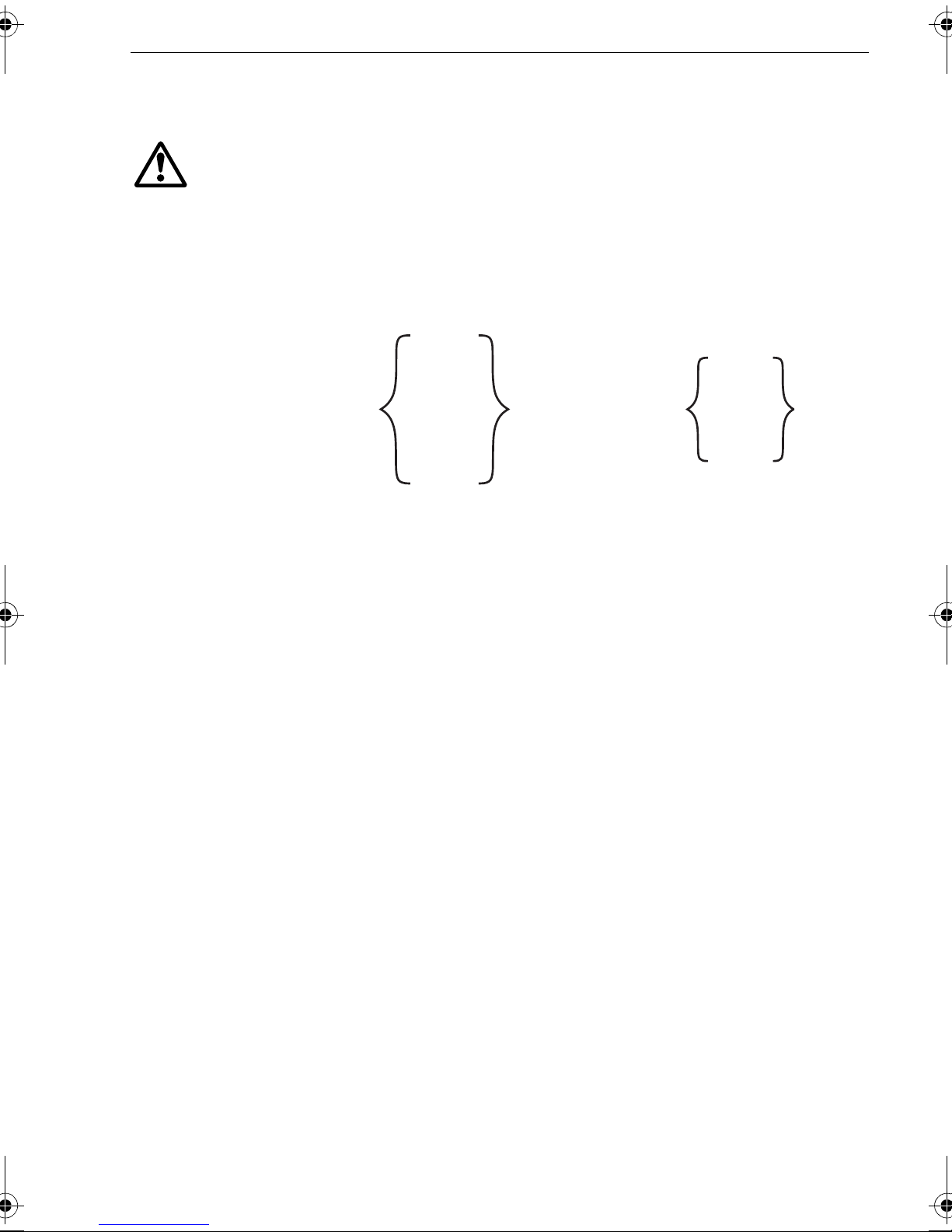
This chapter describes the commissioning and initial setup procedures for the
following combinat ions of Raymarine SmartPilot X (SPX) autopilot systems and Pilot
Controllers:
SPX-10
or
SPX-30
ny of these systems
or
SPX-SOL
or
SPX-CAN
controlled by any of
these controllers
1
ST6002
or
ST7002
or
ST8002
Note:
If your SPX system is controlled with an ST70 Pilot Con troller , the informatio n in this
book does not apply . Instead use the procedures in
System Comm issioning
This book does NOT apply to SPX-5 systems or to systems using ST70 Pilot Controllers.
ST70 AutoPilot Contro ller - SPX
(part no. 81287), to co mmission the s ystem.
Requirement
The commissioning procedures are mandatory and must be carr ied out after
installatio n, before an SPX system is used to steer the boat. The commis sioning
procedures compri ses a series of dockside preparatory p rocedures and a short
seatrial.
Additional setu p procedures enab le you to fine tune your SPX syst em for optimum
performance with your boa t. These procedures are not manda tory and you may find
that you do not need to use them if the SPX system operate s to your satisfaction after
commissioning.
SPX-CAN systems
An SPX-CAN system connected to a V olvo Penta I PS system, must be autoconfigured in acc ordance with the p rocedure in the SPX-CAN In stallation Guide,
before attemptin g to commission the SPX-CAN system.
If you experience any problems whe n commissioning and setting up an SPX-CAN
system connect ed to a Volv o Penta IPS system, repeat the auto conf iguration
procedure, then sta rt the commissioning pro cedure again.
Page 8
2 SmartPilot X-Series Commissioning & Setup Guide
Rudder reference information
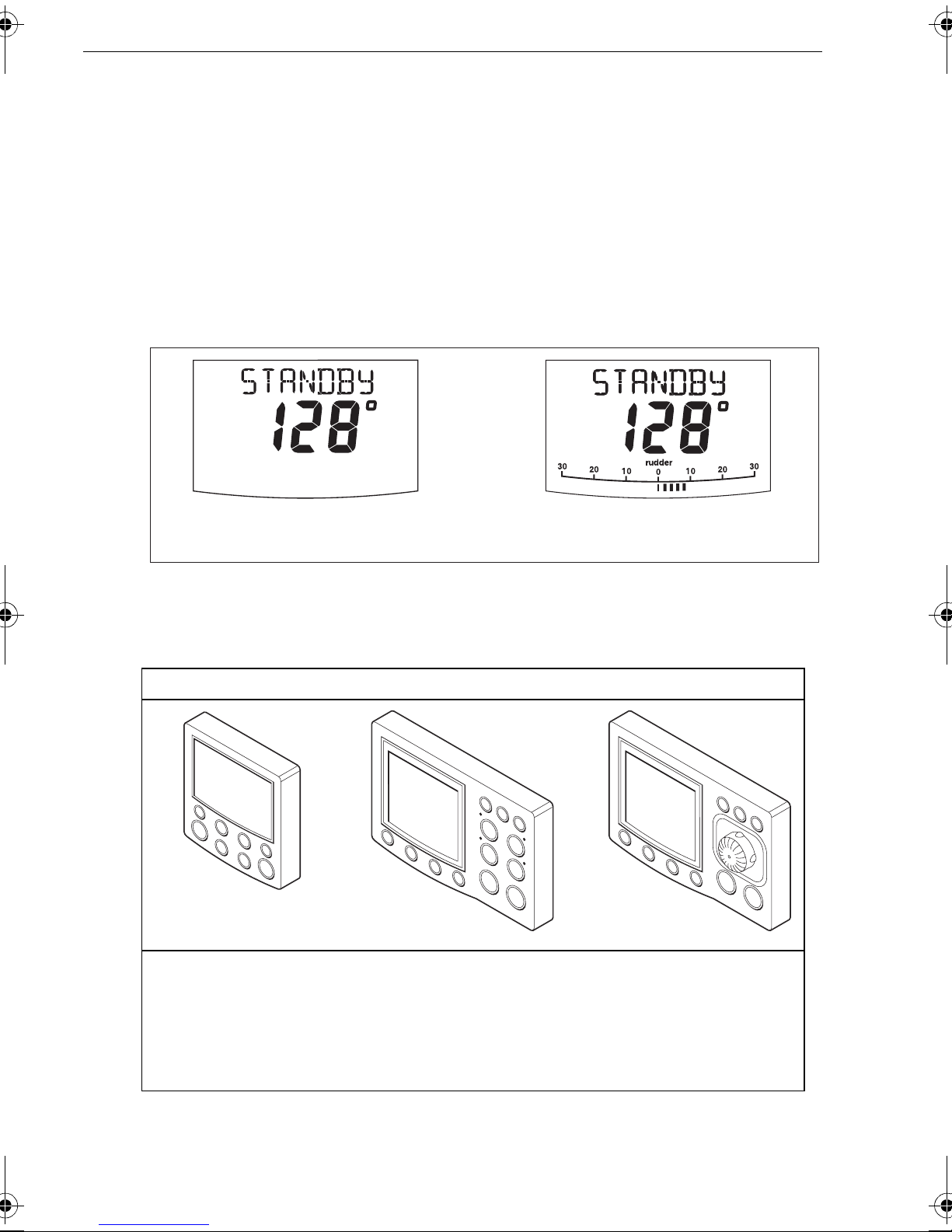
In SPX-30, SPX-SOL & SPX-CAN systems, the ru dder position is shown by a rud der
reference bar and indica tor on the Pilot Controller display .
Note:
The SPX-30 and SPX-SOL systems obtain rudder reference information from a rudder
reference transducer. The SPX-CAN system rudder reference information is provided by the associated Volvo IPS system.
The basic SPX-10 system is supplied without a rudder referenc e transducer, so in the
basic system, the Pilot Controll er display doe s not show a ru dder reference b ar or
indicator . However , the SPX-10 system is comp atible with th e Raymarine rudder
reference transduce r, and this ca n be fitted as an option.
Display in basic SPX-10 system
Display in systems with rudder reference
information
D10779-1
SeaT alk Controller differences
Minor diffe rences in the control functio ns of the ST6002 , ST7002 and ST80 02
SeaT alk Pilo t Controllers are as follows:
ST6002 Controller ST7002 Controller ST8002 Controller
D6400-1
• standby & auto
function keys
• +1, -1, +10 & -10 course
change keys
• disp & track extended
function keys
• standby & auto
function keys
• +1, -1, +10 & -10 course
change keys
• resp, track, mode, res’m,
disp, up & down extended
function keys
D6401-1
• standby & auto
function keys
• Rotary course change control
• resp, track, mode, res’m,
disp, up & down extended
function keys
D6402-1
Page 9
Chapter 1: Procedures 3
1.2 Commissioning procedures
Dockside preparation
The dockside preparation p rocedures compris e:
1. Switching on.
2. Checking Sea T alk and NMEA 0183 c onnections.
3. Checking rudder bar and steerin g operating sen se, for either:
• SPX-10, SPX-30 & SPX-SOL s ystems
or
• SPX-CAN system
4. Dealer calibratio n settings. The se are:
• Setting vess el type and drive type.
• Aligning rudd er bar (if rudder re ference transdu cer fitted).
• Setting rudd er limits ( if rudder reference t ransducer fitted ).
WARNING: Ensure safe control
For saf e control of your boat, you MUST complete the dockside
preparation before starting the initial seatrial.
If you are commi ssioning an SPX-CA N system connec ted to a V olvo Pen ta IPS
system, ensu re the IPS syste m has been auto-c onfigured in ac cordance with the
procedure in the SPX-CAN Installat ion Guide, before attempting to carry out the
commissioni ng procedure.
With the boat safely tied up, complete the following dockside preparation.
Step 1 - Switching on
1. When you have installed your SPX system , switch on the main power br eaker .
TRUE
D10524-1
2. If the SPX controll er and computer a re active, the con troller will beep a nd show
the controller ty pe for a few se conds, then sh ow the
Y ou may also see a
CALIBRA TE R EQUIRED
short time if either:
• The vess el type is not s elected.
• The comp ass is not calibrated.
These will be calibrated during commissioning.
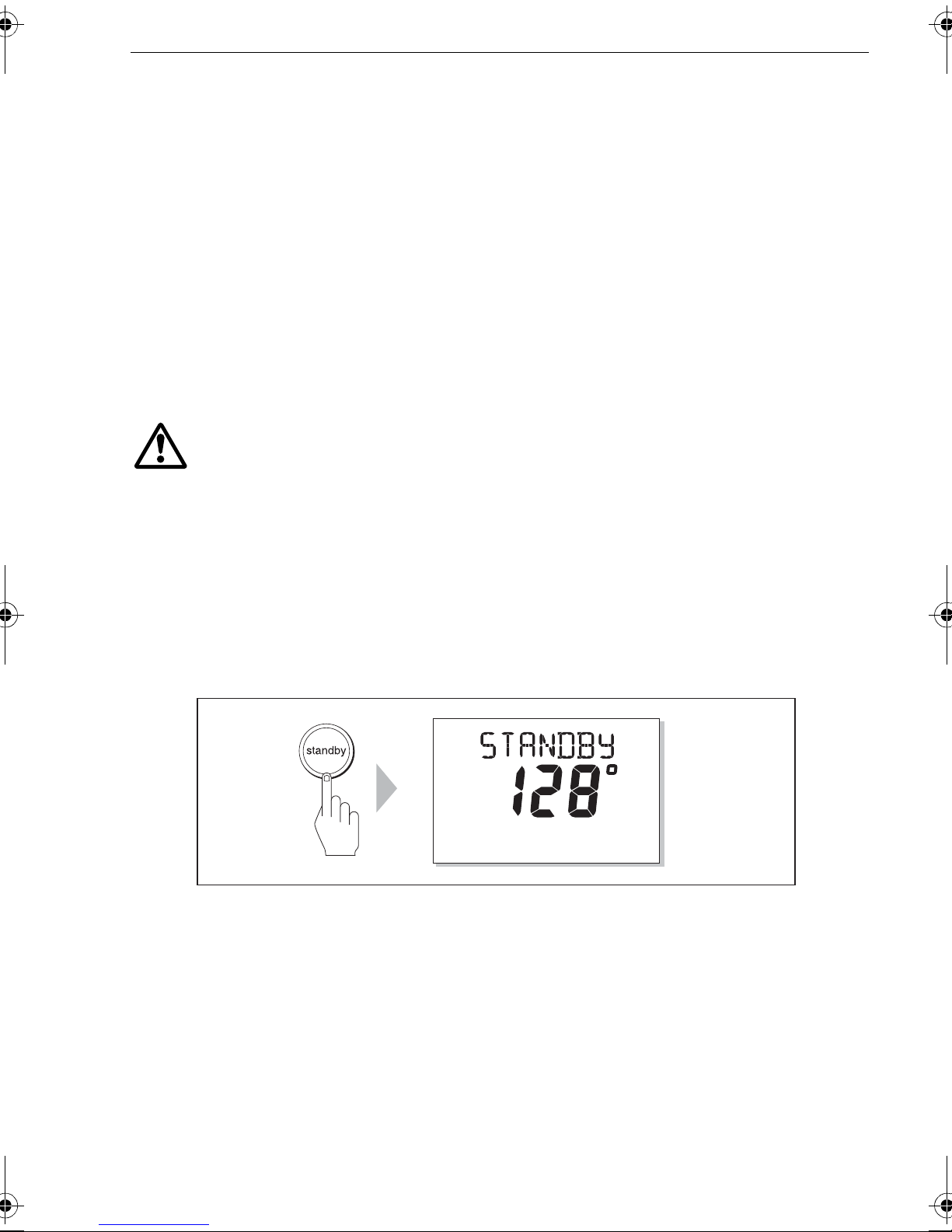
3. Check that the
STANDBY
screen display s a live comp ass heading .
STANDBY
message. This is displayed for a
screen.
Page 10
4 SmartPilot X-Series Commissioning & Setup Guide
Troubleshooting
• If the Pilot Control ler does not b eep or the disp lay is blank , switch of f the power ,
then check the fuse/circuit brea ker and the SeaT alk fuse in the SPX Course
Computer.
• If the display shows the
SEA T ALK FA IL
or
NO PILOT
alarm me ssage, check th e
SeaT al k connections.
• If the
STANDBY
screen does not display a live compass heading, ch eck the sensor
connections.
Step 2 - Checkin g SeaT alk and NMEA conne ctions
SeaT alk connections
If you have c onnected the Pilot Cont roller to other SeaT a lk instruments or controllers,
check the lin ks as follow s:
1. Select display lighting level 3 (
controllers.
2. Check that the Pi lot Controller display light s are on. If th e lights are not on, check
the SeaTal k cabling be tween the Pilot C ontroller and t he other unit s.
LAMP 3)
on one of the oth er SeaT alk instrume nts or
NMEA navigator connections
If the SPX system i s connected to a n NMEA navigator , ensure this is providing
waypoint info rmation, then c heck the links by displayin g the default n avigation dat a
pages on the Pilot Controller:
1. Press
disp
to display the first data page (
XTE
), and check that this page show s the
expected dat a.
2. Press
disp
again to check each successive data page (
BTW, DTW
etc).
If the display shows dashes instead of da ta values, ensure:
• The navigator is switched on and transmitting an active waypoint.
• The navigator is configured to tra nsmit the requ ired data format .
• There is not a cabling error . Check for ope n circuit, short circuit or revers ed wires.
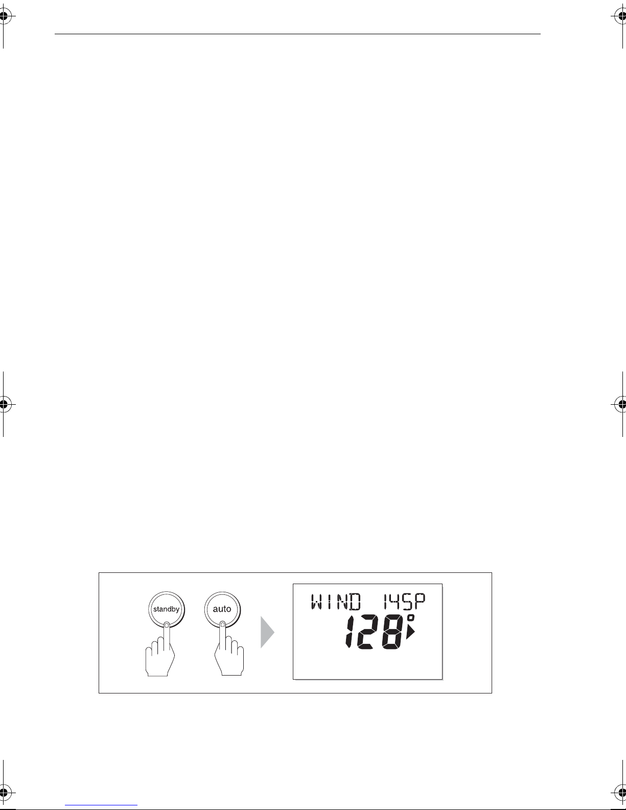
Wind instrument connections
If the SmartPilot is connected to a SeaTalk or NMEA wind instrument, check the links
as follows:
1. Simultaneous ly press
standby
and
auto
.
+
2. Check that the Pilot Control ler displays the Wind V ane mode sc reen, with the
locked wind an gle and locke d heading. If WIND mode is not displayed, the SPX
system is no t receiving win d data. Ch eck the wind in strument and c onnections.
MAG
D10532-1
Page 11
Chapter 1: Procedures 5
Step 3 - Checking rudder bar and steering operating sense
Carry out the proc edures appropriate to the system y ou are commission ing, i.e for
either:
• SPX-10, SPX-30 or SPX-SOL system
or
• SPX-CAN system connected to a V olvo IPS system.
SPX-10, SPX-30 & SPX-SOL systems
If a rudder referen ce transducer is fi tted, check the ru dder bar operatin g sense as
follows:
1. Turn the wheel manua lly to st arboard.
2. Check that th e rudder bar on the controller d isplay moves t o starboard.
If the rudder bar moves the wrong way:
i. Turn off the power .
ii. Reverse th e red and green wires connected to the
SPX Course Computer .
iii. Switc h on the power and re-check.
RUDDER
inputs on the
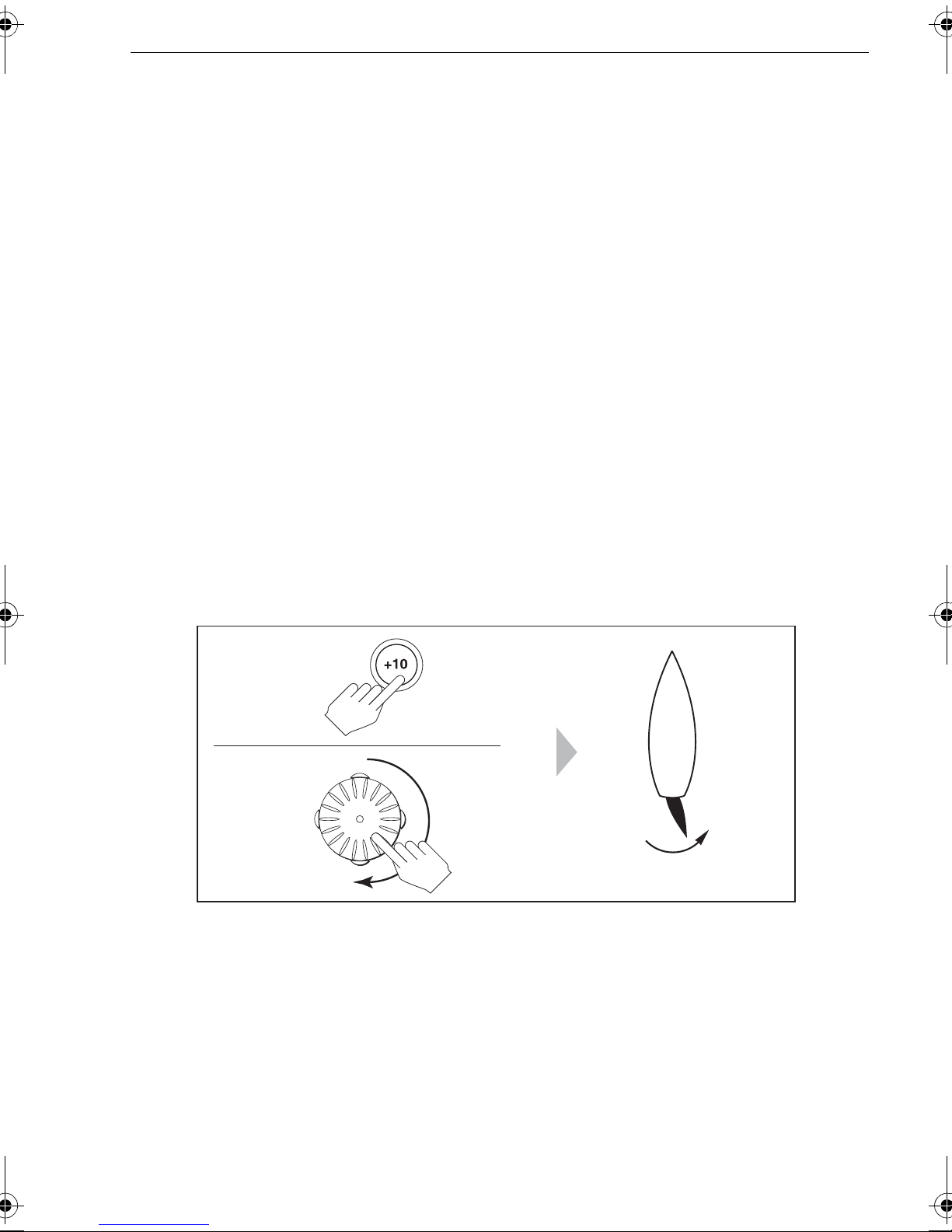
Check the stee ring operating sense as follo ws:
1. Manually center the w heel, then press
2. Check that th e display sh ows
AUTO
.
auto
so the SPX system is in Auto mode.
Be ready to press standby if the rudder moves hardover .
3. Press the +10 key once or turn the rotary control ½ turn clockwise.
ST6002
ST7002
ST8002
½ turn
D10745-1
4. Check that the ru dder moves to starboard a few degrees, then stop s. If the rudder
drives hard over , immediatel y press
movement.
5. If the rudder moves to port or the rudder drives hard over:
i. Press
standby.
ii. Turn off the p ower .
iii. Reverse th e motor wires (on SPX-10 & SPX-30) or solenoid wi res (on
SPX-SOL), connec ted to terminals A and B on the SPX Course Comput er.
iv . Switch o n the power an d re-check.
standby
to prevent further rudder
Note:
need to increase the rudder damping level manually (See
If the rudder overshoots and has to drive back or starts to hunt back and forth, you will
page 30
).
Page 12
6 SmartPilot X-Series Commissioning & Setup Guide
SPX-CAN system connected to V olvo IPS system
Before making any ad justments to an SPX-CAN system, ensure the autoconfiguration p rocedure (see the
SPX_CAN System Inst allation Guide
) has bee n
carried out.
Check the rudde r bar operatin g sense as follo ws:
1. Power up the SPX-CAN system
2. St art the boat e ngine.
3. Turn the wheel manually .
4. Check that the ru dder bar on the controller dis play follows th e helm movemen t.
If the rudder bar does not follow the helm, ensure the SPX-CAN system wiring is
correct.
Check the st eering operating sense as fo llows:
1. Manually center the w heel.
2. With the boat en gine running , press
auto
.
Be ready to press standby if the rudder moves hard over .
3. Press the +10 key once or turn the rotary control ½ turn clockwise.
4. Check that the ru dder moves to starbo ard a few degrees, then stop s. If the rudder
drives hardover , immediately pr ess
standby
to prevent f urther rudder moveme nt.
Step 4 - Dealer calibration settings
Introduction
WARNING: Use Dealer calibra tion correctly
Improper use of Dealer calibration can seriously impair the SPX
system performance and therefore adversely affect the
steering capability . Do not change Dealer calibration settings
other than as described in the product documentation.
T o proceed with the dockside preparation, you need to carry out certain Dealer
calibration se tup functions. The exact requ irement and co nsequently the calibration
screens displayed, depend on whic h SPX system you are calibrating a nd whether a
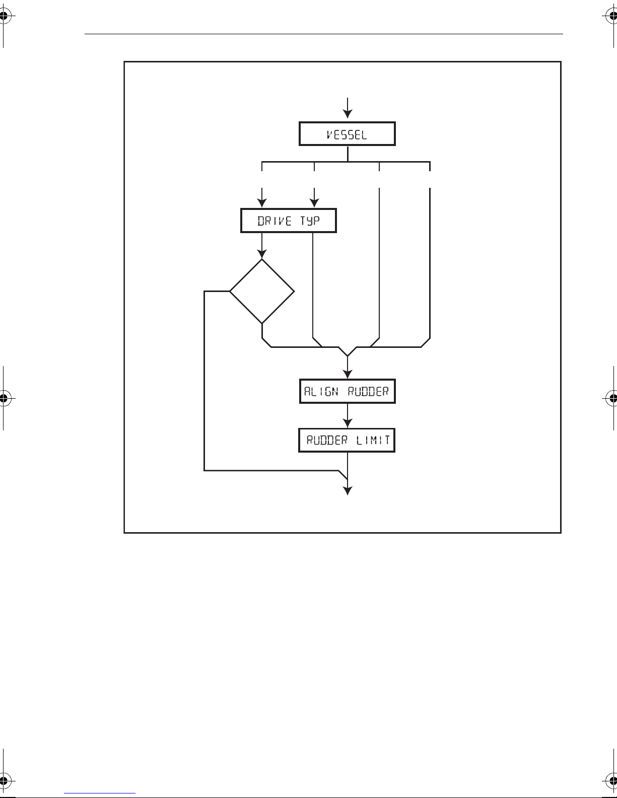
rudder reference transdu cer is fitted, as summarized in the following diagram.
Page 13
Chapter 1: Procedures 7
Setup map
CAL
screen
No
Enter
DEALER CALIBRATION
CAL
screen
SPX-10 SPX-30 SPX-SOL SPX-CAN
Rudder ref
fitted
Yes
CAL
screen
CAL
screen
Leave
DEALER CALIBRATION
D10787-1
Entering Dealer calibration
Enter Dealer cali bration as foll ows:
1. Ensure the SPX syste m is in S tandby m ode.
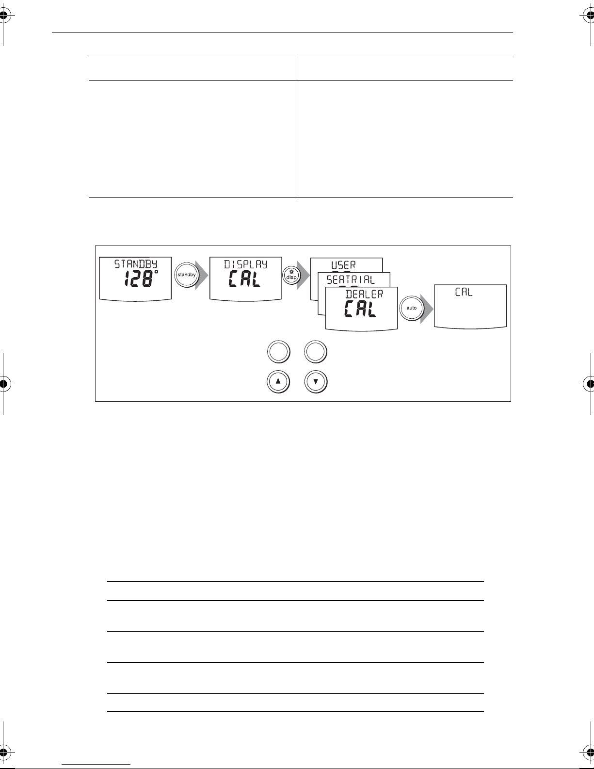
2. Referring to the fo llowing table , use the appro priate procedure to enter Dealer
calibration mo de.
Page 14
8 SmartPilot X-Series Commissioning & Setup Guide
ST6002 Controllers ST7002 and ST8002 Controllers
1 Press and hold
to enter the Calibration mode
2 When the screen shows
disp
press
screen
3 Press
4 Simultaneously press -1 and +1 to enter
Note:
auto
Dealer calibration mode
For more information on settings and calibration modes, refer to
tem settings
standby
until you see the
: the display will change to
for two seconds
DISPLAY CAL
DEALER CAL
.
2 sec
At the CAL screen, press + together to enter DEALER CAL
1 Press and hold
enter the Calibration mode
2 When the screen shows
,
press
disp
you see the
CAL
3Press
4 Simultaneously press -1 and +1 (on the
auto
ST7002) or the up and down arrows (on the
ST8002), to enter Dealer calibration mode
standby
or the up and down arrows, until
DEALER CAL
: the display will change to
for two seconds to
DISPLAY CAL
screen
Chapter 2: SPX sys-
x3
-1 +1
or
+
(ST8002 only)
,
CAL
D10746-1
3. In Dealer calibra tion, access the vessel typ e screen, using
vessel type screen shows either
VESSEL
or one of the vessel type s (
SEMI DISPLACE, PLANING, STERN DRV, WORK BOA T
disp
or
SAIL BOA T
if necessary . The
DISPLACE
,
).
Setting vessel type
The vessel ty pe setting aut omatically determ ines appropriat e default valu es for
various other calibra tion settings. Some of these settin gs are checked later in this
procedure and other s should not require any adj ustment. The default valu es for each
vessel type are liste d on
page 35
.
Set the vessel type as follo ws:
1. Use
-1
or
+1,
or the
rotary control
to set the appr opriate vessel ty pe, as in the
following tab le.
Type Description
DISPLACE
SEMI DISPLACE
PLANING
Power-driven boats which do not plane
(Typically below 15 kt s top speed)
Faster power-driven boats which do not plane
(Typically 15-20 kts top speed)
Planing boats with inboard engine(s) and shaft drives
(NOT boats with outdrives)
STERN DRV
Boats with outdrives or outboard engines
Page 15
Chapter 1: Procedures 9
Type Description
WORK BOAT
SAIL BOAT
2. Press
the
Setup map
disp
to confirm yo ur selection and mo ve to the next calib ration screen. See
diagram abov e.
Commercial tugs, fishing vessels, etc
Sailing boat
Setting drive type
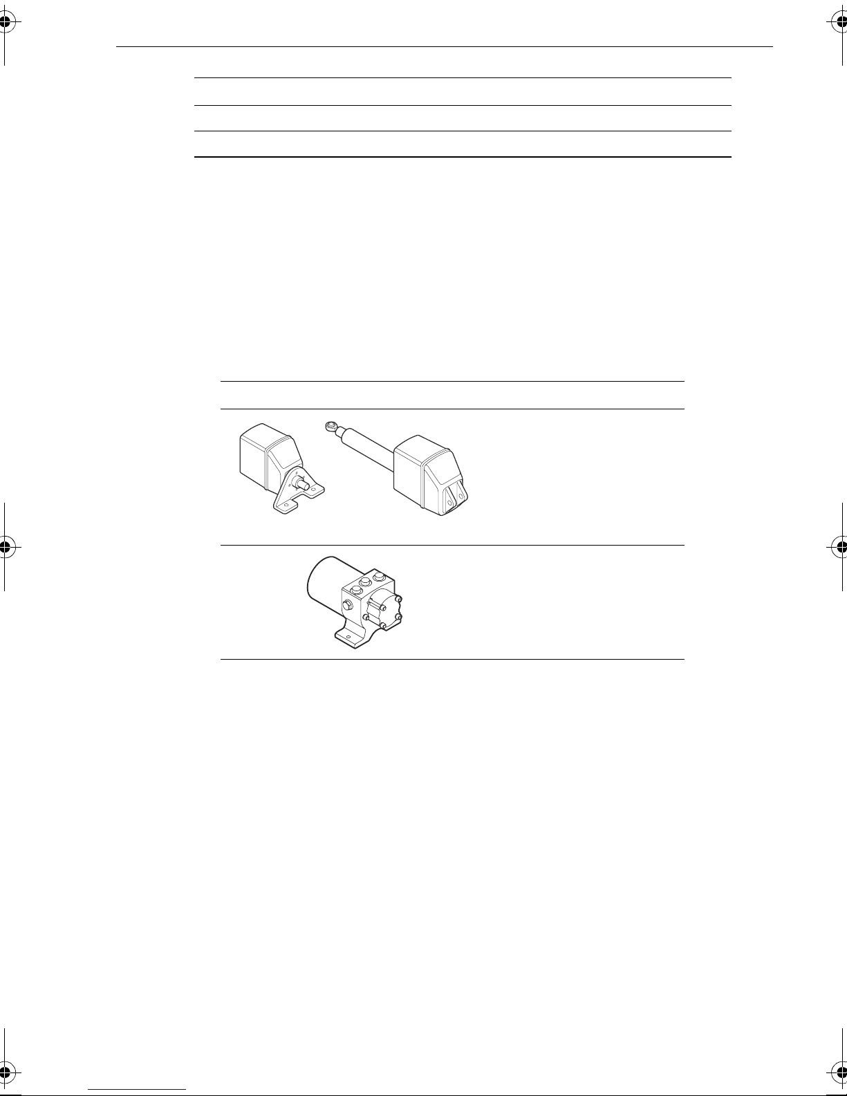
Note:
TYP calibration screen is not displayed.
On SPX-SOL and SPX-CAN systems, the drive type is set automatically so the DRIVE
On SPX-10 and SPX-30 s ystems the
type as follows:
1. Use
-1
or
+1,
or the
rotary control
following tab le.
Drive Drive Type Setting
DRIVE TYP
screen is d isplayed. Set t he drive
to set the appropri ate drive type , as in the
Drive Type 3
Linear
Rotary
Typically found on yachts
1
-
1
9
7
0
1
D
I/O (stern)
Found on Powerboats
Drive Type 4
Hydraulic reversing pump
Used on yachts and power-
boats with hydraulic steering
D10792-1
2. Press
the
disp
to confirm yo ur selection and mo ve to the next calib ration screen. See
Setup map
diagram abov e.
Aligning rudder bar
If a rudder referen ce transducer is fi tted, the
ALIGN RUDDER
screen is di splayed.
Align the rudder indicato r as follows:
1. Use the wheel to center the rudde r.
2. Use
-1
or
+1,
or the
rotary control
to adjust the rudd er indicator so it is at the
center of the rud der bar on the Pi lot Controller display .
The maximum adjus tment available is ± 9°. If the offset is bey ond these limits, you
will need to physically a djust the alig nment of the s ensor .
3. Press
the
Note:
page 13
disp
to confirm the rud der bar alignment and move to the next sc reen. See
Setup map
diagram abov e.
You can also zero the rudder bar with the boat underway during the initial seatrial (see
).
Page 16

10 SmartPilot X-Series Commissioning & Setup Guide
Setting t he rudder limits
If a rudder referen ce transducer is fi tted, the
rudder limits as fol lows:
1. Turn the wheel to mo ve the rudder:
i. To the port end st op and note the angle on th e rudder bar .
ii. To the starboard end stop and note t he angle on th e rudder bar .
2. Use
-1, +1, -1 0
than the lowest angle you h ave noted.
and
+10
or the
rotary control
RUDDER LIMIT
to set the rudder limit to 5° le ss
page dis played. Set the
Finishing dockside preparation
Hold down
to Standby mode.
standby
for 2 seconds to save the Dealer calibration settings and return
Seatrial calibration
When you have successfully completed the dockside prepara tion, carry out a Seatrial
calibration, to cal ibrate the compass and set up the autopilot steerin g characteristics.
Important
If you need to return to manual steering at an y time during a Seatrial or any other
procedure, press the standby button. NEVER compromise vessel safety.
EMC conformance
Always check t he installation before going to sea to make sure that it is not af fected by
radio transmissions , engine starting etc.
This is particularly important when carrying out a Seatrial.
Seatrial conditions
The seatrial m ust be carried out only:
• In conditions of light wind and calm water .
• In waters that are clear of any obstructio ns, so the boat has plenty of clear sp ace
to maneuver .
In order to achi eve optimum autopilot performan ce, course over g round (COG),
speed over grou nd (SOG) or boat speed da ta are required at the SPX system (e.g . on
SeaTalk). Ensure that the equ ipment providing this informati on (e.g. GPS), is
switched on and fully ope rational, before starting a Seatrial.
Getting started
St art the SeaT rial cali bration as follow s:
1. From St andby mode, hold d own
see the
2. Carry out the Se atrial calibrat ion functions as described bel ow , in the follo wing
sequence:
i. Swingi ng the compa ss
ii. Aligning com pass heading
iii. Alignin g rudder bar (onl y if rudder refere nce transduce r is fitted)
iv. AutoLearn
SEATRIAL CAL
screen.
standby
for 2 seconds, then press
disp
twice to
Page 17
Chapter 1: Procedures 11
Swinging the comp ass
Note:
tem. Refer to the handbook supplied with the NMEA compass for information about calibration.
This section does not apply if you have connected an NMEA compass to your SPX sys-
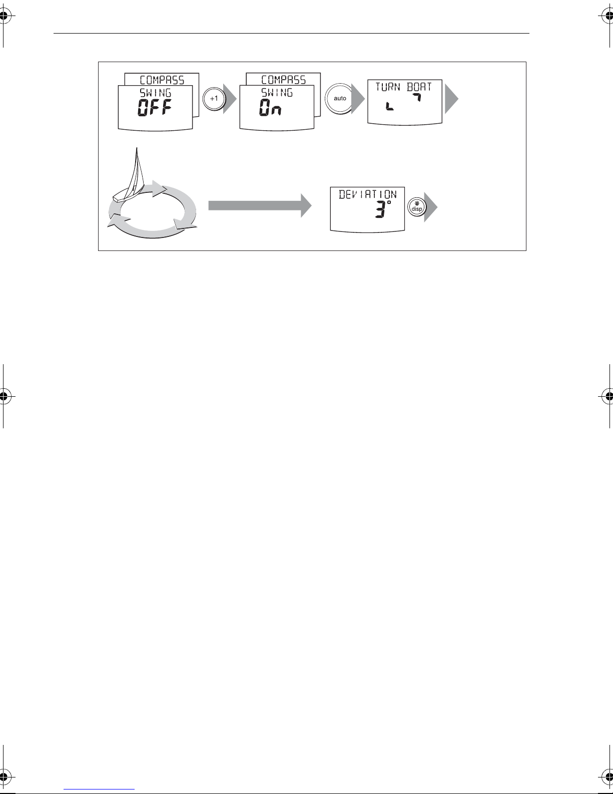
The magnetic deviation correcti on procedure (com monly called “s winging the
compass”) i nvolves turning your boat in sl ow circles so the autopilot can automatically
determine the d eviation and a pply any corre ction required. This procedure red uces
deviation errors to a few degrees .
As magnetic devia tion can cause significant c ompass errors on your boat, you MUST
complete the compass swing before any other seatrial procedure.
T o swing the compass:
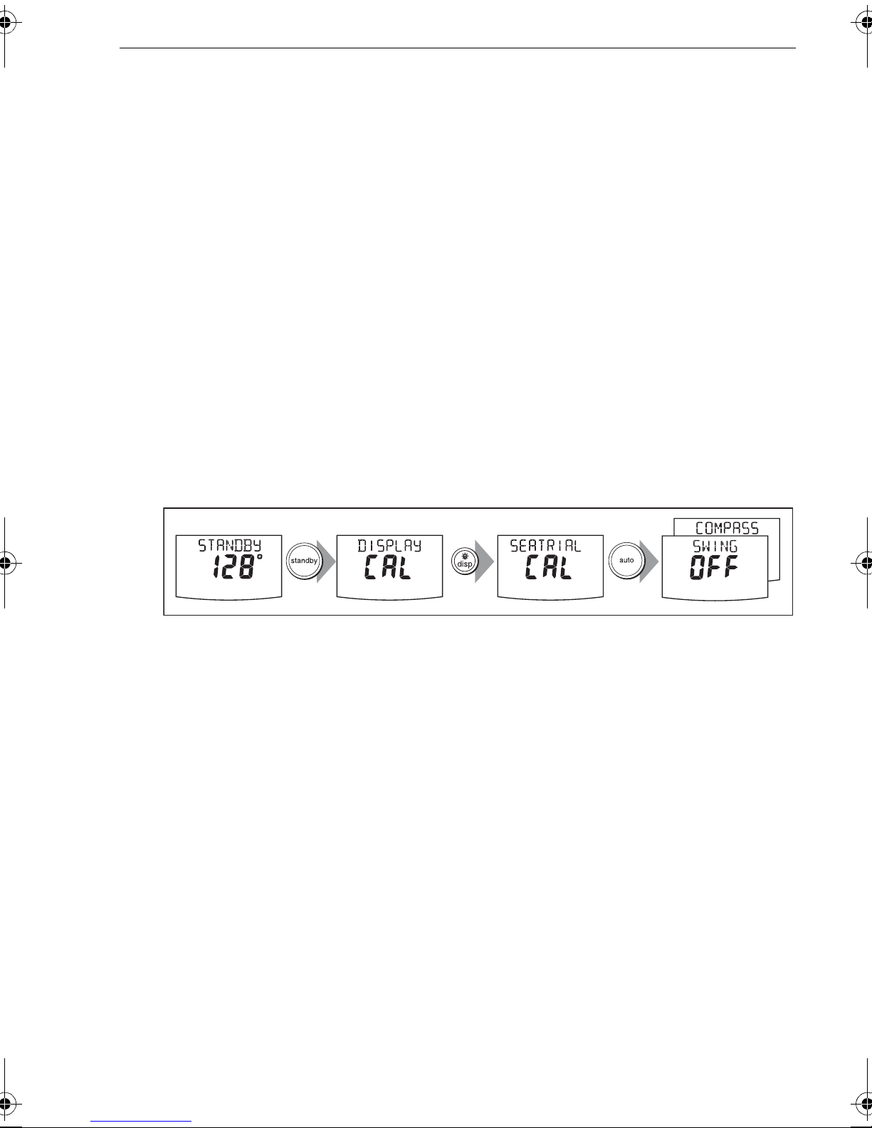
1. With the SPX sys tem in S tandby m ode, enter Seatri al calibration as follows:
i. Hold do wn
ii. When you se e the
SEATRIAL CAL
iii. Press
Note:
If you cannot access Seatrial calibration, disable the calibration lock. (see
2. Use
see
SWING COMPASS.
auto
disp
as necess ary , to move through the Seat rial Calibratio n items until y ou
standby
to enter Seatrial calibration.
for two seconds to enter Calib ration mode.
DISPLAY CAL
screen, press
disp
screen.
until you se e the
page 28
).
2 sec
3. When you are ready to start, pre ss +1, or turn the
select
4. Press
SWING COMPASS ON
auto
to start the com pass swing. The controller will display
.
x2
rotary control
D10541-1
clockwise, to
TURN BOA T
indicating the st art of the calibration process.
5. Ensuring you kee p the boat’s spee d below 5 knots, start slowly turning the boat in
circles at a c onstant sp eed, mainta ining a turn rate of approximat ely 3° per
second, i.e. taki ng approximately 2 minutes to complete one turn. Com plete at
least two ci rcles, in this manner .
If you turn the boat too quickly, the display will sh ow a
TOO FAST
message. If thi s
occurs, apply less he lm to reduce the rate of turn.
Note:
want to repeat the deviation correction, return to the
If necessary, you can quit the correction process by pressing
SWING COMP A SS
standby
screen.
or
disp
. If you then
Page 18
12 SmartPilot X-Series Commissioning & Setup Guide
Start
turning boat
Slowly turn boat in circles:
• at a turn rate of 3˚ per second
• keeping boat speed below 5 knots
Minimum of
2 circles
Keep turning the boat until
you see the DEVIATION screen
to Align Heading
D10761-1
6. Continue slowl y turning the boat until the con troller beeps and displays t he
DEVIATION
screen. This ind icates that the SPX system has compl eted the
deviation corre ction.
Note:
This screen shows the maximum deviation over 360° (not as an east/west value).
If the deviatio n figure exceeds 15°, the comp ass is being affected by ferrous object s
on your boat. You should mov e the compass to a better lo cation. Higher de viation
figures are acc eptable on steel boats .
Aligning comp ass heading
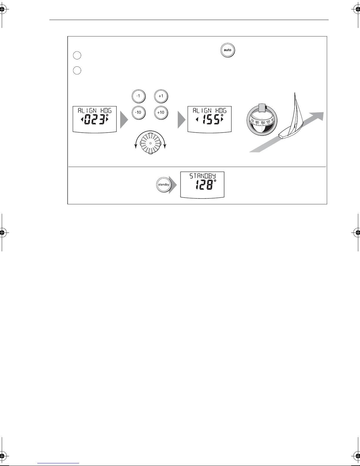
Once the deviation is displayed, press
ALIGN HDG
(
) page, then:
1. Manually stee r the boat on a steady co urse at a spee d suffic ient to hold th e
course.
2. If you have a GPS connected to your SPX system:
• Increase the boat spe ed to more than 3 knots.
•Press
auto
. The SPX system will then set the head ing to agree with the COG
(course over ground) heading rec eived from the G PS.
disp
to move to the Align Heading
As many facto rs can cause a differe nce between hea ding and CO G , you must finetune the heading al ignment to match the b oat’s steering com pass (or a known trans it
bearing). T o do thi s:
1. Use
-1, +1, -10
and
until it match es the boat’ s steering com pass (or a k nown transit bea ring).
2. Hold down
standby
compass settings.
+10
or the
rotary control
to adjust the dis played headin g
for 2 seconds to exit Seatrial calibration and save the new
Page 19
Chapter 1: Procedures 13
Align the autopilot heading
Coarse adjustment: If COG is available from GPS, press to set autopilot heading to
a
COG value, then fine tune manually (see below).
Fine adjustment: If COG is not available (or after setting heading to COG),
b
align autopilot heading manually:
ST6002 & ST7002
or
or
Autopilot heading
Steering compass
=
ST8002
Adjust the autopilot heading so it shows the same value as the boat's steering compass
Save changes
2 sec
To:
• save deviation correction
• save heading alignment
• return to STANDBY mode
Although comp ass calibratio n removes most of the align ment error , small erro rs (a
few degrees) may remain. Onc e you have c ompleted the in itial comp ass calibrati on,
you can make further adjustm ents to the alignment with out having to s wing the
compas s again.
Check the heading reading against a number of known hea dings, plot a deviation
curve, and determine the h eading alignm ent value that will give th e lowest average
alignment error . You can then ente r this value on th e Heading Ali gnment screen, a s
described a bove.
Known
heading
D10777-1
If the average h eading error is more than 5°, che ck there are no items close to the
compass that could cause an unwanted magnetic influence. Y ou should also consider
moving the flu xgate comp ass and perfo rming the comp ass devia tion correction
procedure again , circling mo re slowly and i n more favorabl e conditions.
Aligning rudder bar
If the rudder refe rence transduce r is fitted, use t his procedur e to align the rudder bar
on the Pilot Controller displ ay:
1. Access the
i. From Standby mode, hold down
to see the
ii. Press
ALIGN RUDDER
2. Ste er straight ahead then use
displayed rudder bar to zer o.
ALIGN RUDDER
screen in Sea trial calibration:
standby
SEA TRIAL CAL
auto
to enter Seatrial calibration, t hen press
screen.
screen.
-1, +1, -10
and
for 2 seconds, then press
disp
tree times to see the
+10
or the
rotary control
disp
twice
to set the
Page 20
14 SmartPilot X-Series Commissioning & Setup Guide
AutoLearn
WARNING: Ensure there is enough clear sea space
The AutoLearn process tak es the boat through a number of
maneuvers, which can result in sudden, sharp turns, especially
when the AutoLearn function is run on more maneuv erable
boats. Therefore, ensure there is a significant amount of CLEAR
SEA SP ACE in front of the boat, bef ore starting an AutoLearn
process.
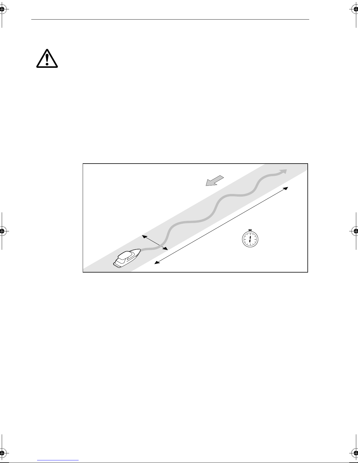
The next st age of the Seatri al is to carry out an AutoLearn routine. This is a selflearning calibra tion feature that automatically adjusts rudder gain, counter rudder and
AutoTrim for optimum performance on your boat.
If you need to ret urn to manual steering at any tim e during an AutoLearn routine o r any
other procedure, press the
standby
button. NEVER compromise vessel safe ty .
Wind
of clear sea space
At least 0.04 nm (100 m)
At least 0.25 nm (500 m) of clear sea space
1 minute
(approximately)
D5495-2
Ensure you hav e sufficient sea room to co mplete the Auto Learn, then carry out the
AutoLearn as fol lows:
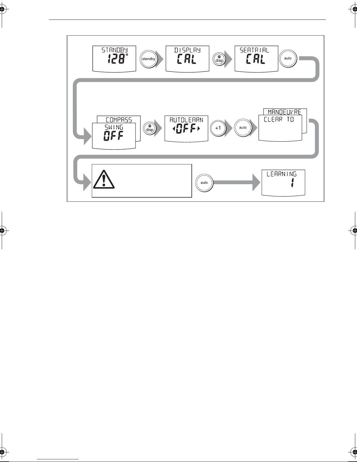
1. If you are not a lready in Seatrial calibration:
i. From Stand by mode, hold down
to see the
ii. Press
iii. Press
SEA TRIAL CAL
auto
to enter Seatrial calibration
disp
four times to see the
2. In Seatrial ca libration, pres s
screen.
disp
standby
AUTOLEARN
for 2 seconds, then press
screen.
as necessa ry , until the
AUTOLEARN
disp
twice
screen is
displayed.
3. With the
AUTOLEARN
screen displaye d, prepare to start the Aut oLearn:
• power boats: stee r straight ahead (rudder centered). For non-planing boats,
set a comforta ble cruising speed. F or planing boats set the spee d so the boat
is just planing.
• sail boats: with the sails down, steer strai ght ahead (rudde r centered) and
motor the boa t at typica l cruising sp eed.
4. If conditions are not calm, head into the wind and waves.
Page 21
Chapter 1: Procedures 15
Enter Seatrial calibration
2 sec
Prepare for AutoLearn
• steer straight ahead at cruising speed
(planing boats – just on the plane)
• head into wind and waves
x2
x4
CHECK!
Before proceeding, ensure
you have sufficient clear
sea space
Start
AutoLearn
AutoLearn in progress
5. When you are re ady to proceed:
• On ST6002 an d ST7002 sy stems, press
• On ST8002 s ystems, turn th e
6. Press
auto
. The screen w ill then show the
rotary control
7. Ensure it is safe to continue , then press
+1
.
clockwise,
CLEAR TO MANO EUVER
auto
to start the AutoLear n maneuvers:
• The boat wil l start a series of zig-zag turns and the display will show
with a numb er to indicate the current AutoLearn stage. This n umber increases
as AutoLearn progresse s.
• A typical AutoLe arn completes within 7 to 27 step s (depending on boat
characteristi cs and sea con ditions).
D10545-1
message.
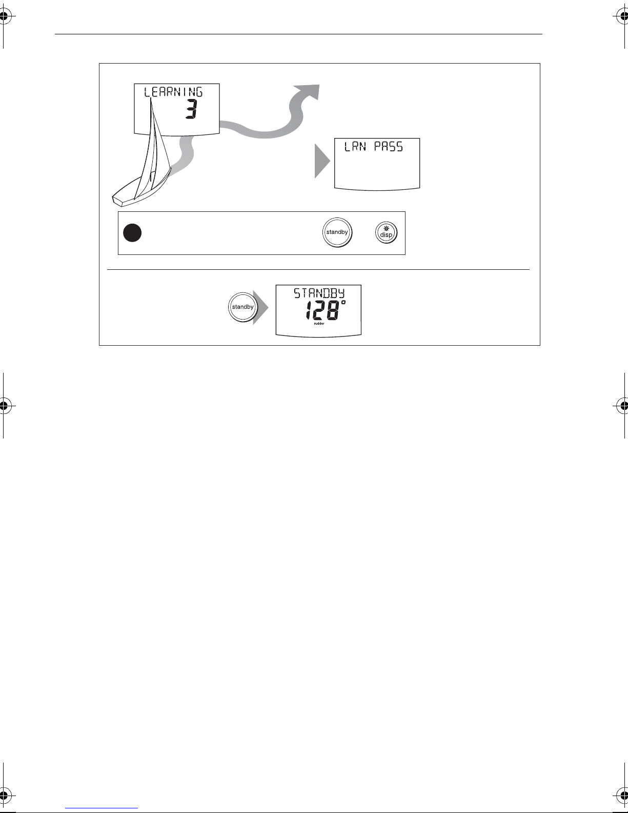
LEARNING
Note:
To cancel an AutoLearn, press
8. When the SPX system has finished l earning, the co ntroller will beep a nd display
either
•
•
LRN P AS S
LRN P ASS
LRN F AIL
code will also be disp layed:
1
= AutoLearn has not been carried out.
2
= AutoLearn failed, due to manua l interruption.
3
Not used.
4
= AutoLearn f ailed, probably du e to drive or c ompass failu re.
5
= AutoLearn failed, probabl y due to motor current limitin g.
6
= AutoLearn failed, probabl y due to boat locking in a turn.
9. If the AutoLearn was succes sful, hold down standby for 2 seconds to store the
new settings.
or
LRN F AIL
standby
:
or
disp
.
= AutoLearn completed successfully
= AutoLearn was not successful, s o should be repea ted. A failure
Page 22
16 SmartPilot X-Series Commissioning & Setup Guide
Boat completes AutoLearn
AutoLearn successful
After
7 to 27
steps
If you need to cancel the AutoLearn, press or
!
Save new settings
2 sec
10.The seatrial is n ow complete. Hol d down
To:
• save AutoLearn calibration settings
• return to STANDBY mode
standby
for 2 seconds to exit Seatrial
Note: If you see a
LRN FAIL message,
press disp to return to
the AUTOLEARN screen
then repeat from Step 2
D10546-1
calibration and save the set tings.
Commissioning complete
If you have successfully completed the dockside preparation and seatrial calibration,
the SPX system is now commissioned and ready for use.
After you have used your SPX syst em, you may decide to change the value of some
parameters t o improve pilo t performance w ith your boat. If you feel th is is necess ary ,
use the appropri ate procedures under
1.3 Manual set-up
Requirement
Checking SPX system operation
Before manually ad justing any s ettings, familiar ize yourself with basic SPX system
operation, as fo llows:
1. Ste er onto a comp ass headin g and hold the course stead y at a normal cruising
speed. If ne cessary, steer the boat manu ally for a short time t o check how the boat
steers.
2. Press
locked heading in calm sea conditions.
3. Use
and starboard .
4. Press standby to return to man ual steering.
auto
to lock onto the c urrent heading. The SPX system shoul d hold the
-1, +1, -10
and
+10
Manual setup
, below.
and observe how the SPX system alters the course to port
Page 23

Chapter 1: Procedures 17
Adjustab le parameters
If you feel you ne ed to fine tune the SPX s ystem performance, you c an do so by using
one or more of the procedures below to adjust:
• Rudder gain.
• Counter rudder
• AutoTrim.
If your SPX system ‘hunts’, i. e. continuousl y moves the ste ering backwards an d
forwards by sma ll amounts , you can als o adjust rudder damping to pre vent this.
Over time you may wis h to repeat these adjustme nts using a range of sea cond itions
and headings to achieve optim um all-round pe rformance for your particular v essel
and preferences .
Adjust these s ettings when mo toring your boa t at cruising s peed.
Setting response level
Before proceeding with any manual adjustme nt, set the response level to 5 as follows:
1. Enter Dealer calibrati on as described on
2. Use
3. Use the
4. Hold down
disp
-1
calibration.
as necessary to ac cess the
or
+1
key or the up and
standby
for 2 secon ds to save the setting and l eave Dealer
down
page 7
RESPONSE
arrow keys to set a response of 5.
.
screen.
Rudder gain
Boats can v ary widely in their response to helm , and by adjusting th e rudder gain you
can change the s teering characteristics of th e SPX system. Rudder gain i s a measure
of how much helm the SPX system ap plies to correct cou rse errors – hig her settings
mean more rudder is appli ed.
Checking
Complete the followi ng test to determine whether the rudde r gain is set correctly:
1. Ensure you have s et the SPX response to level
2. Motor your boat at a typical cru ising speed in clear water .
It is easier to recognize the st eering response in calm sea conditi ons where wave
action does no t mask steeri ng performance.
3. Press
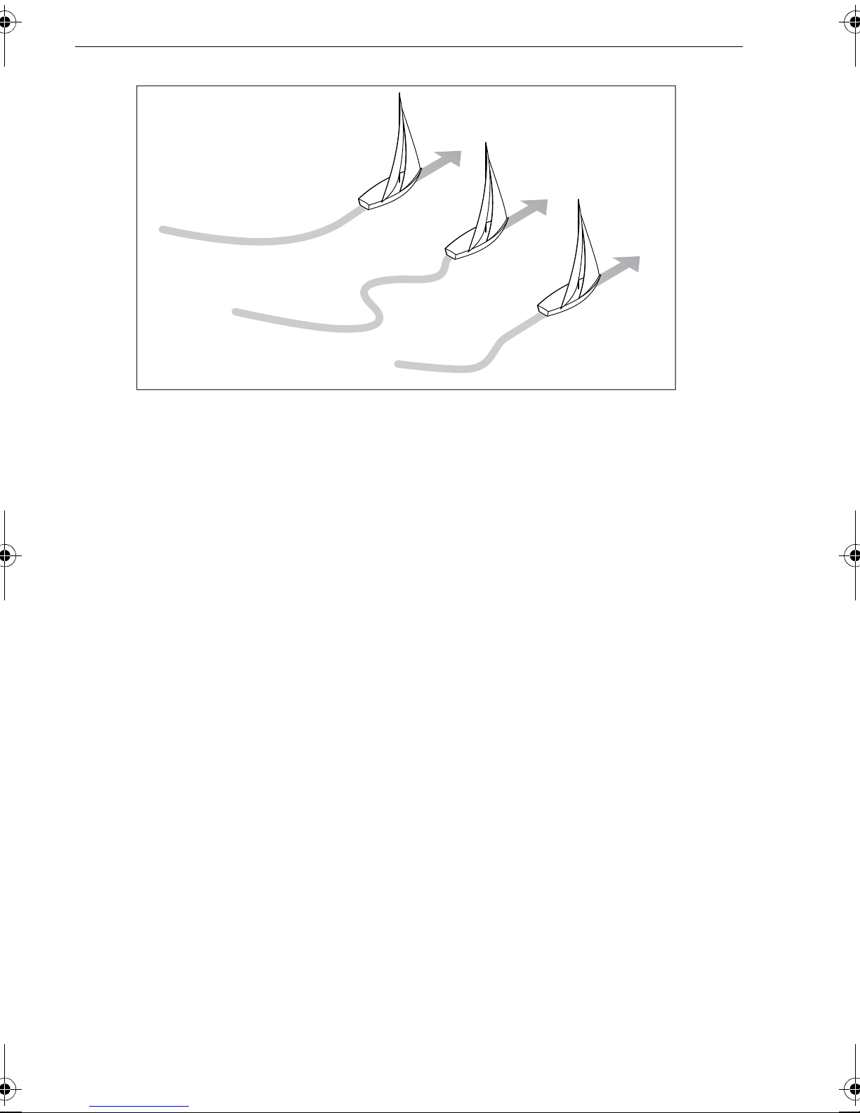
• If the rudder gain is adjusted correctly , the 40° course change should result in
• If the rudd er gain setting is too high, the 40° course cha nge will result in a
• If the rudder gain is too low , the boat’s performance will be sluggish – it wil l take
auto
to enter Auto m ode, then alter course by 40°:
a crisp turn followed by an overshoot of no m ore than 5°.
distinct ove rshoot of more than 5° and the re may be a distinct ‘S’ i n the course,
as at (A).
Correct this oversteer by reducing the rudder gain, as described below.
a long time to make the 4 0° turn and there will be no ov ershoot (B).
Correct this u ndersteer by increasing the rudder gain, as described below .
5
, as describe d above.
Page 24
18 SmartPilot X-Series Commissioning & Setup Guide
New
heading
B
New
Rudder gain
too low
heading
A
Rudder gain
too high
Correct
rudder gain
New
heading
D3262-3
Adjusting
T o adjust the rud der gain:
1. Enter Dealer calibrati on as described on
2. Use
3. Use the
4. Hold down
disp
as necessary to ac cess the
-1
or
+1
keys or the
standby
for 2 second s to save the changes and leave Deale r
rotary control
page 7
.
RUDD GAIN
to adjust the rudd er gain.
screen (see
page 30
).
calibration.
5. Press
auto
to check SPX system performance in Auto mode.
Counter rudder
Counter rudder is the amount of rudder the SPX system applies to try to prevent the
boat oversteering . Higher counter rudder settings re sult in more rudder being appli ed.
Checking
T o check the counter rudder setting
1. Ensure you have set the response to level
5
, as described above .
2. Motor your boat at cruising s peed in clear water .
3. Press
auto
to switch the SPX s ystem to Auto mode, then make a 90° course
change:
• When gain an d counter rudde r are both set c orrectly , the boa t performs a
smooth cont inuous turn with minimal ove rshoot.
• If the counter rudder is too low, the boat will still overshoot.
• If counter rud der is too high , the boat will ‘fight the turn’ and make a seri es of
short, sharp turns: this resu lts in a v ery ‘mechanical ’ feel as the boat changes
course.
Adjusting
T o adjust the co unter rudder:
1. Enter Dealer calibrati on as described on
2. Use
disp
as necessary to ac cess the
page 7
.
COUNT RUD
screen (see
page 30
).
Page 25

Chapter 1: Procedures 19
3. Use -1 or +1 or the
4. Hold down
calibration.
5. Press
standby
auto
to check the SPX system performance in Auto mode .
rotary control
for 2 secon ds to save the changes and leave Deale r
to adjust the coun ter rudder .
AutoTrim
Y ou may also nee d to adjust the AutoTri m setting. AutoT rim determines how quick ly
the SPX system app lies ‘standin g helm’ to correc t for trim changes caused, for
example, by c hanges in the wind load on the sails or s uperstructure, or an imbalance
of engines.
Increasing the AutoT rim level reduces the time the SPX system takes to get back onto
the correct course , but makes the boa t less stable . If the SPX system:
• Gives unstable course keepin g and the boat ‘snakes’ aro und the desired c ourse,
decrease th e AutoT rim level
• Hangs off course for excessive periods of time, increase the AutoT rim level
Adjusting
Before attempting to adjust the AutoTrim setting, ensu re you have suf ficient
experience using the SPX system .
On sail boat s you can only evaluate the effect of AutoT rim while un der sail.
If you need to adjust AutoTrim, go up one level at a time and use the lowest acceptable
OFF
value. The possible setting s range from
correction).
T o adjust the Auto Trim:
1. Enter Dealer calibrati on as described on
2. Use
3. Use
4. Hold down
5. Press
disp
-1
or +1 or the rotary control, to adjust the AutoTrim le vel.
calibration.
auto
as necessary to ac cess the
standby
to check the SPX system performance in Auto mode .
for 2 secon ds to save the changes and leave Deale r
(no trim correction) to 6 (fastest trim
page 7
AUTOTRIM
.
screen (see
page 30
).
Rudder damping
On SPX systems with a rudder reference tr ansducer, y ou can set the rudde r damping
to prevent autop ilot ‘hunting’ , i.e. contin uously movi ng the steering backwards a nd
forwards by sma ll amounts . T o set up the rudde r damping:
1. Enter Dealer calibrati on as described on
2. Use
3. Use
4. Hold down
disp
as necessary to ac cess the
-1, +1, -1 0
hunting stop s. Use the low est rudder dam ping value at which hunting stops..
calibration.
and
standby
+10
or the
for 2 secon ds to save the changes and leave Deale r
rotary control
page 7
RUDD DAMP
.
to set the rudder damping so the
page.
Page 26

20 SmartPilot X-Series Commissioning & Setup Guide
Page 27

Chapter 2: SPX system settings
2.1 Introduction
This chapter describ es the SPX system calibration setti ngs and factor y default
settings. The calibr ation settings can be adj usted to best suit your operatin g
requirements , but as many will have been adjuste d to optimum values when
commissioni ng the system, t hey should no t normally require further change.
If you change th e calibration settings after the SPX system has been commissio ned,
you do not nee d to repeat t he commissi oning process. However , DO NO T manually
adjust autopil ot settings bef ore the commiss ioning procedures in
been completed
Calibration modes
There are four calibration modes, namely Display ca libration, User calibration,
Seatrial calibra tion and Deal er calibration.
.
Chapter 2
21
have
Each calibratio n mode uses a s eries of screens to set calib ration values.
Display calibration
The items in Display calibration affec t only the SPX system Pilot Contro ller. The y are
stored in the c ontroller and d o not affec t any other control lers connected th rough
SeaTalk.
Y ou can adjust the Displa y calibration settings as often as necessary – for example, to
add or change inform ation displayed on dat a pages.
User calibration
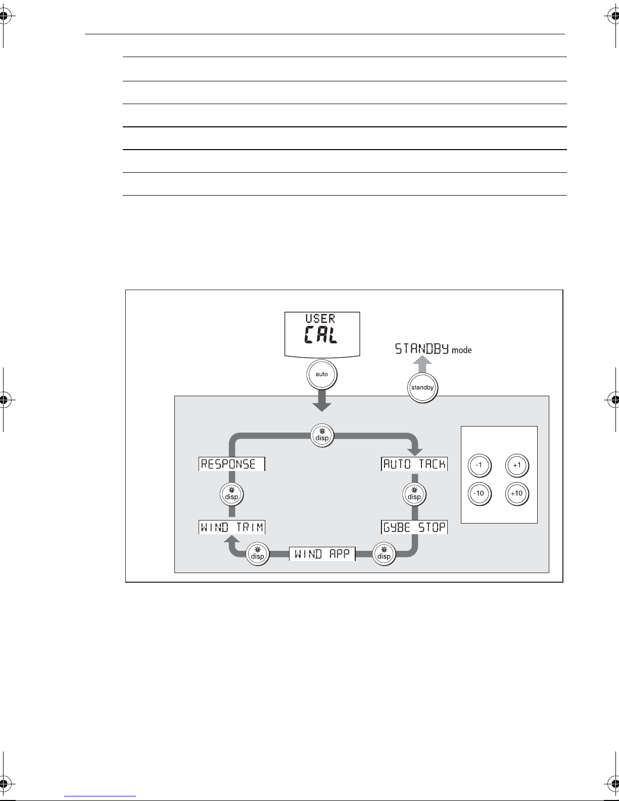
The User cal ibration mode in cludes settings that you may need to adjust on a regular
basis to respo nd to changin g conditions.
Seatrial calibration
The Seatrial calibration m ode is used ONL Y when commissioning you r SPX system,
as described in
calibration during normal operation .
Chapter 3,
so is not d escribed again h ere. Do not access Seatrial
Dealer calibration
The Dealer calibrati on mode includes items that hav e a significant impact on
operation and c an affect y our boat’s s afety .
After you have completed t he initial i nstallation and seatrial, you should no t normally
need to alter th e Dealer calibra tion values.
Page 28
22 SmartPilot X-Series Commissioning & Setup Guide
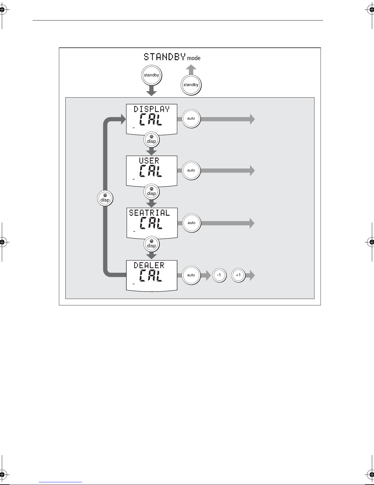
Accessing the Calibration modes
Accessing
Calibration Modes
Calibration
Modes
2 seconds
2 seconds
(saves changes)
to enter display
calibration mode
to enter user
calibration mode
to enter seatrial
calibration mode
CAL ?
+
to enter dealer
calibration mode
Adjusting calibration values
T o adjus t calibration values:
1. Access the require d calibration mode (refer to th e diagram above).
2. Press
press and hold
3. Use
When you have m ade all required chan ges, press and hold
save changes and exi t.
disp
to scroll th rough the avai lable options. T o v iew the previous option,
-1, +1, -10
disp
for 1 second.
and
+10
to change th e values.
standby
for 2 seconds to
D10647-1
Page 29
Chapter 2: SPX system settings 23
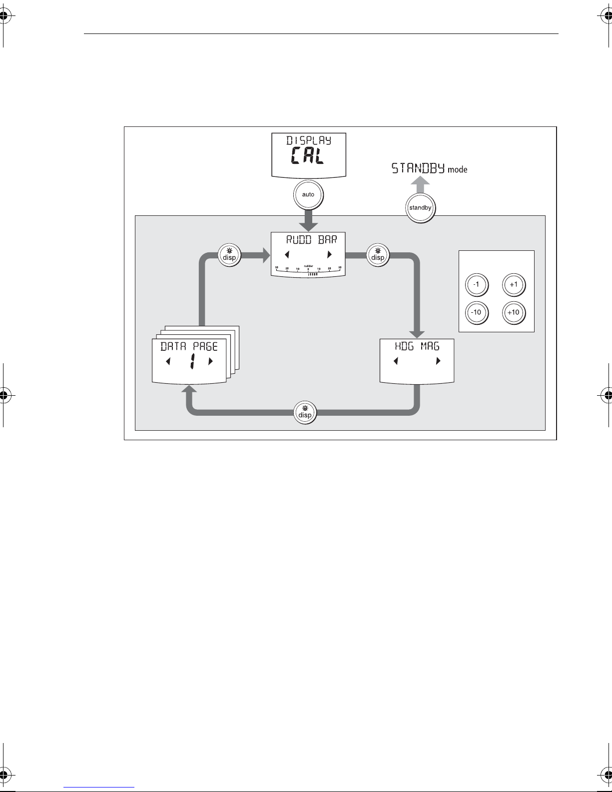
2.2 Display calibration
Display calib ration provides settings to a djust the informati on displayed on the Pilot
Controller.
Accessing Display
Calibration
2 seconds
(save changes)
Display Calibration
To adjust values
The RUDD BAR parameters are
adjustable only if the rudder
reference transducer option is fitted
Data pages
Press disp
for next page
or
or
D10602-1
RUDD BAR screen
This screen gives yo u access to the other Display cal ibration screens.
HDG screen
Y ou ca n choose whethe r to use magnetic or true headin g data valu es. The options
are:
•
HDG MAG
heading values, duri ng normal operation.
•
HDG TRUE
heading values, duri ng normal operation.
- Magnetic heading. If yo u select this , the screen wil l indicate
- Tr ue heading. I f you select this the screen will indicate
TRUE
MAG
for
for
Data pages
The Pilot Controller has fifteen user-configura ble data pages. Each dat a page can be
configured to d isplay SeaTalk/NMEA data , which can be viewed durin g normal
operation.
Page 30

24 SmartPilot X-Series Commissioning & Setup Guide
The default dat a page s ettings are:
Data Page Default Sett ing
1
2
3
4
Remaining pages
XTE
(Cross Track Error)
BTW
(Bearing to Waypoint) - see Note below
DTW
(Distance to Waypoint) - see Note below
RESPONSE
NOT USED
(see
Setting up data pag es
below)
Setting up data pages
When setting up your data pages, we recommend that you:
• Retain the
overboard (MOB) mess age, these data pages w ill show the bearing and dista nce
to the MOB location.
• Disable data pages you do not need to
displayed durin g normal operation, thereby improving the access time to the other
data p ages.
.
Available Data Pages Displayed as
Speed Knots
BTW
and
DTW
data pa ges. If your SPX sys tem receives a man
NOT USED
SPEED KTS
. These will the n not be
Log
Trip
Average Speed
Wind Direction e.g.
Wind Speed
Depth Metres
Depth Feet
Depth Fathoms
Heading
Water Temperature, Degrees C
Water Temperature, Degrees F
Course Over Ground
Speed Over Ground, Knots
LOG XXXX
TRIP XXX.X
AV. SPD
WIND KTS
DEPTH M
DEPTH FT
DEPTH FA
HEADING
WATER °C
WATER °F
COG
SOG KTS
.X
WIND PORT
- see Note below
- see Note below
- see Note below
- see Note below
- see Note below
Cross Track Error
Distance to Waypoint
XTE
DTW
Page 31
Chapter 2: SPX system settings 25
Available Data Pages Displayed as
Bearing to Waypoint
Rudder Gain
Response
Watch
Universal Time Coordinated
Note:
There are 3 depth data pages (meters, feet and fathoms) and 2 water temperature data
pages (°C and °F). The SPX system will display the depth data or water temperature in the units
defined by the data page you select.
2.3 User calibration
Accessing User Calibration
User Calibration
BTW
RUDD GAIN
RESPONSE
WATCH
UTC
- used to control the Watch timer
2 seconds
(save changes)
To adjust values
or
or
D10506-1
For information on how to acces s User calibration, see
modes, p age 22
.
Accessing th e Calibration
The User cal ibration mode in cludes settings that you may need to adjust on a regular
basis to respo nd to changin g conditions.
Page 32

26 SmartPilot X-Series Commissioning & Setup Guide
AutoT ack (sail boat only)
Use this scree n to select ho w the vessel p erforms when using AutoTack. You can
either:
• Set a default AutoTack angle. T his is the an gle through whic h the boat will turn
when an AutoTack is perform ed.
or
• Select Relative T ack operation. With Relative Tack selected, the apparent wind
angle when Au toT ack is initiated, is mirrored th e other side of the wind, on th e
opposite tack.
Screen Text Options
AUTO TACK
40° to 125° in 1° steps
Setting default AutoT a ck angle
T o s et the required Au toT ac k angle:
• If the SPX system is receiving wind inf ormation, set the AutoT ac k angle to the
required change of heading.
• If the SPX system is not receiving wind in formation, set the AutoT ack angle to 20°
greater than the actual required change of head ing.
For example, to tack through 80° (i.e when sailing at 40° to the wind), set the
AutoTack angle to 100°.
Selecting Relative T ack
T o select Relative Tack, use -1 and
action select s Relativ e T ac k and the sc reen displa ys
-10
, to reduce the tack angl e value to 30°. This
rEL
, to indicate t his.
Gybe inhibit (sail boa t only)
With gybe inhi bit on:
• Y ou will be able to perform an AutoTack into the wind
• The SPX system will prevent the boat from performing an AutoT ack away from the
wind, to prevent accidental gybes,
With gybe inhi bit off, yo u can perform an Au toTack into or away from th e wind.
Screen T e xt Option s
GYBE STOP
Wind selection (sail boat only)
This screen determines whether the boat steers to apparent or true wind in Wind V ane
mode.
Options
WIND APP
WIND TRUE
(Default) SPX system steers to apparent wind angle
ON (Default) = Gybe inhibit on (gybes prevented)
OFF = Gybe inhibit off (gybes permitted)
SPX system steers to true wind angle
Page 33
Chapter 2: SPX system settings 27
WindTrim (sail boat only)
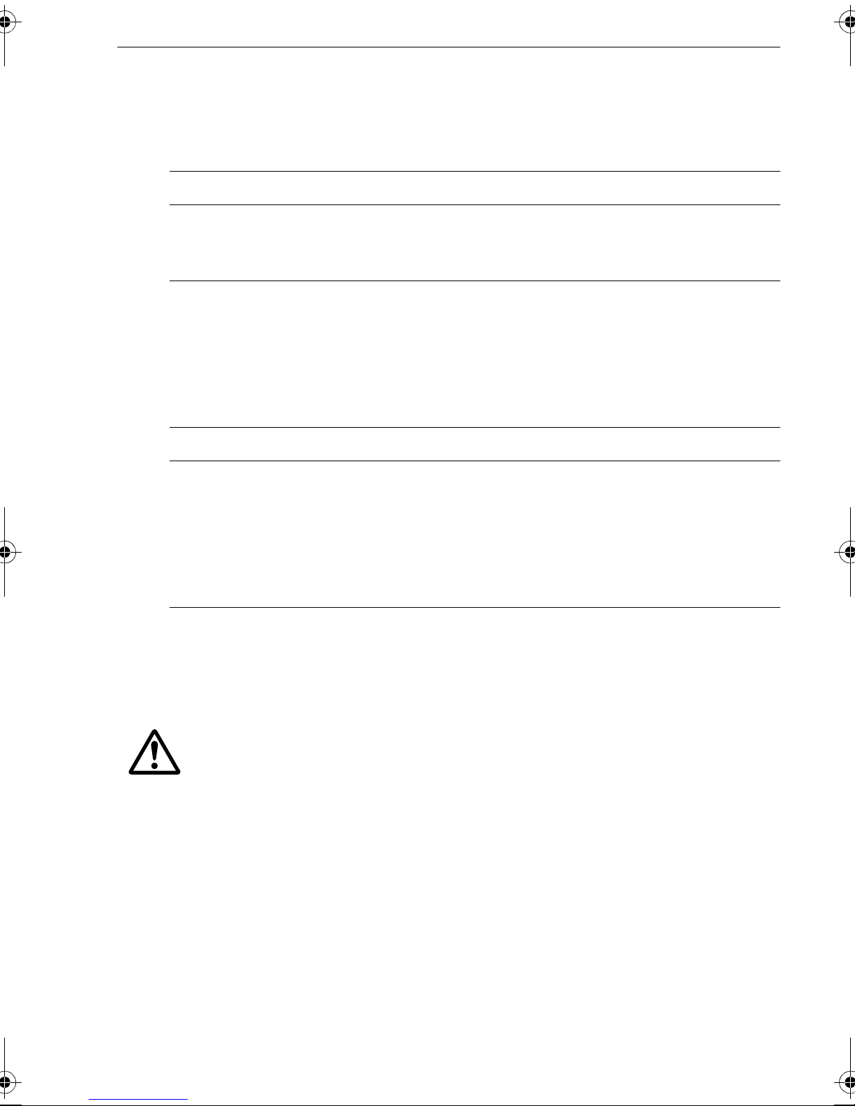
WindTr im controls how quickly the SP X system respond s to changes in the wind
direction. Hig her wind trim settings will result in a sy stem that is more responsiv e to
wind changes.
Screen T e xt Option s
WIND TRIM
Range = 1 to 9
1 to 3 - Least responsive to wind changes (less system activity)
4 to 6 - Moderate response to wind changes
7 to 9 - Most responsive to wind changes (more system activity)
Response level
This sets the default SPX s ystem response l evel. The respons e level cont rols the
relationship betwe en course keeping accuracy and the amount of helm/drive ac tivity.
Y ou can make temporary changes to response during normal operation, as describ ed
in the Pilot Controller Op erating Guide.
Screen T e xt Option s
RESPONSE
Range = 1 to 9
Levels1 to 3 minimize the amount of pilot activity. This conserves
power, but may compromise short-term course-keeping accuracy
Levels 4 to 6 should give good course keeping with crisp, well con-
trolled turns under normal operating conditions
Levels7 to 9 give the tightest course keeping and greatest rudder
activity (and power consumption). This can lead to a rough passage
in open waters as the SPX system may ‘fight’ the sea.
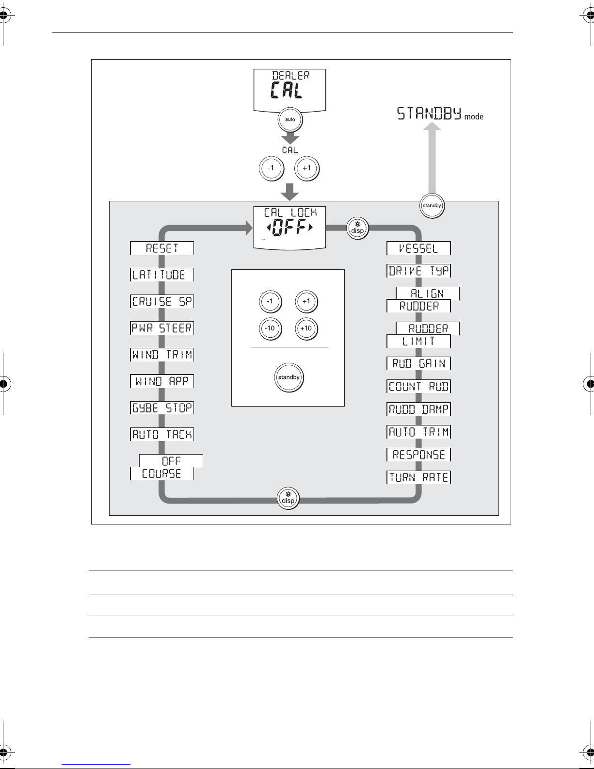
2.4 Dealer calibration
For information on how to acces s Dealer calibration, see
modes, p age 22
WARNING: Dealer calibration
Changing the Dealer calibration values can hav e a significant
affect on the SPX system steering characteristics and therefore
on the safety of your boa t.
Some Dealer calibratio n values are adjusted during the commissioning process (se e
Chapter 1: Commissioning & setup
commissione d you should not normally need to change Dealer calib ration values.
However if you decide you want to chang e Dealer calibra tion values, b e aware that
many of these have a sig nificant impact on the SPX system operation and can
affect your boat’ s safety .
.
Accessing the Calibra tion
), and once th e SPX system h as been
Page 34
28 SmartPilot X-Series Commissioning & Setup Guide
Accessing
Dealer Calibration
+
2 seconds
(saves changes)
Dealer Calibration
To adjust values
or
or
To exit & save changes
2 seconds
Seatrial calibration loc k
This screen c ontrols the ac cess to Seatrial c alibration.
Screen te xt Options
CAL LOC K OFF
Calibration lock off – Seatrial calibration can be accessed (default)
D10762-1
CAL LOC K ON
V essel type
Selecting the c orrect vessel type, enables the SPX system to set appro priate values
for other calibration settings, to give optimum performance. Refer to the table on
for default values.
35
Calibration lock on – Seatrial calibration cannot be accessed
page
Page 35
Chapter 2: SPX system settings 29
Options
DISPLACE
Power-driven boats which do not plane
(Typically below 15 kt s top speed)
SEMI DISPLACE
Faster power-driven boats which do not plane
(Typically 15-20 kts top speed)
PLANING
Planing boats with inboard engine(s) and shaft drives
(NOT boats with outdrives)
STERN DRV
WORK BOAT
SAIL BOAT
Boats with outdrives or outboard engines
Commercial tugs, fishing vessels, etc
Sailing boat
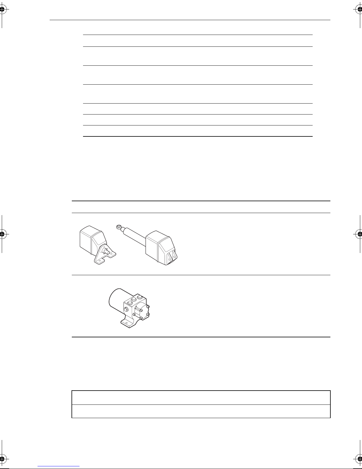
Drive type
The drive type setting controls ho w SPX-10 and SPX-30 systems drive the steering
system.
Note:
played, as the drive type is set automatically.
On SPX-SOL and SPX-CAN systems, the DRIVE TYP calibration screen is not dis-
Drive Driv e Type Setting
Drive Type 3
Linear
Rotary
Typically found on yachts
I/O (stern)
Found on Powerboats
D6404-1
Drive Type 4
Hydraulic reversing pump
Used on yachts and powerboats with hydraulic
steering
D6405-1
Align rudder
The align rudde r screen is disp layed only if a rudder referenc e transducer i s fitted.
If a rudder reference transducer is fitted , use this screen is used to calibrate the rudder
bar display . This should be set when comm issioning the SPX system (see
Screen Text Range
ALIGN RUDDER
-9° to +9° in 1° step s
page 34
).
Page 36

30 SmartPilot X-Series Commissioning & Setup Guide
Rudder limit
The rudder limi t screen is di splayed only i f a rudder referenc e transducer i s fitted.
If a rudder referen ce transducer is fitted, this s creen is used to set the limit s of the
rudder control j ust inside the mechanical end stops, and thus avoi d putting the
steering syste m under unnec essary load. T his should be s et when commi ssioning
the SPX system
Screen T ext Range
RUD LIMIT
(see page 10).
10° to 40° in 1° steps
Rudder gain
Rudder gain is a m easure of how much helm the SPX syste m applies to co rrect
course errors. T he higher the setti ng the more rud der will be appl ied.
The rudder ga in setting is se t automatic ally as par t of the AutoLear n process
page 14
(see
.
Screen T ext Range
).
RUDDER GAIN
1 to 9
Counter rudder
Counter rudder is the amount of rudder the SPX system applies to try to prevent the
boat from yaw ing off co urse. Higher coun ter rudder settin gs result in more ru dder
being applied.
The default counter rud der gain is set as part of the initia l seatrial AutoLearn proce ss
page 14
(see
Screen T ext Range
COUNT RUD
).
1 to 9 (Do NOT set to 0)
Rudder damping
On SPX systems with a rudder reference t ransducer, y ou can set the rudder damping
to prevent autop ilot ‘hunting’ . Increasing the rudder dampin g value reduces hunting.
When adjusting the value, inc rease the dampin g one level at a time until the autopilot
stops hunti ng. Always u se the lowest a cceptable v alue
.
Screen T ext Range
RUDD DAMP
AutoTrim
The AutoT rim setting de termines the rate at which the SPX system applie s ‘standing
helm’ to correc t for trim chan ges caused by varying wind lo ads on the sails or
superstructure.
1 to 9
Page 37

Chapter 2: SPX system settings 31
The default AutoTrim is set as part of the AutoLearn process (see
page 14
).
If you need to change the se tting, increase the AutoT rim one l evel at a time and use
the lowest accept able value:
• If the SPX system gives unst able course keeping or excessive dri ve activity with a
change in the heel angle, de crease the Au toTrim level.
• If the SPX system reac ts slowly to a heading chang e due to a ch ange in the hee l
angle, increas e the AutoT rim leve l.
• If the AutoT rim level i s too high, the boat will be l ess stable and snake a round the
desired course.
Setting Effect
AUTO TR IM OFF
AUTO TR IM 1
to
6
No trim correction
Auto trim applied:
1 = Slowest, 6 = Fastest
Response level
This sets the default SPX system re sponse level setti ng. The response le vel controls
the relationshi p between cours e keeping accura cy and the am ount of helm/driv e
activity . Y ou c an make temporary c hanges to response d uring normal operatio n
your
Pilot Controller Operating Gui de
Screen T e xt Option s
for detai ls).
(see
RESPONSE
Range = 1 to 9
Levels1 to 3 minimize the amount of pilot activity. This conserves
power, but may compromise short-term course-keeping accuracy
Levels 4 to 6 should give good course keeping with crisp, well con-
trolled turns under normal operating conditions
Levels7 to 9 give the tightest course keeping and greatest rudder
activity (and power consumption). This can lead to a rough passage
in open waters as the SPX system may ‘fight’ the sea.
Turn rate limit
This limit s your boat’s rate of turn und er SPX system cont rol.
Screen T ext Range
TURN RATE
1° to 30° per second in 1° steps
Off course angle
This screen determines the angle used by the
Operating Guide
). The
OFF COURSE
alarm operates if the pi lot strays off course by
more than the s pecified angl e for more than 20 seconds.
Screen T ext Range
OFF COURSE
alarm (see your
OFF COURSE
15° to 40° in 1° steps
Page 38
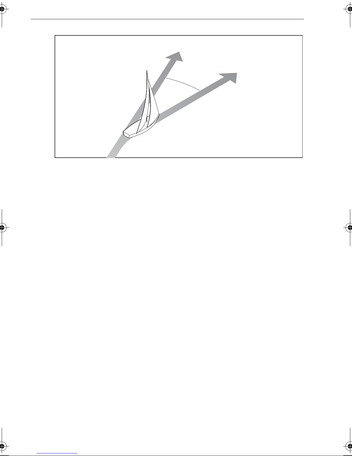
32 SmartPilot X-Series Commissioning & Setup Guide
Locked heading
Boat heading
15˚ minimum
D10648-1
AutoTack
The AutoTack angle is the angle through which the bo at will turn wh en you select an
automatic t ack (see
page 26
).
Gybe inhibit
With gybe inhi bit on:
• Y ou will be able to perform an AutoTack into the wind
• T o prevent accident al gybes, the SmartPilot will prevent the boa t from performing
an AutoTack away from the wi nd
With gybe inhi bit off, yo u can perform an Au toT ac k into or away from the wind. Se e
also
page 26
.
Wind selection
Note:
This screen determines whether the boat steers to apparent or true wind in Wind V ane
mode. See
Only available if appropriate wind data is available.
page 26
.
WindTrim
WindTr im controls how quickly the SP X system respo nds to changes in the wind
direction. Hig her wind trim settings will result in a sy stem that is more responsiv e to
wind changes. S ee
page 27
.
Power Steer
If you have a joystick connecte d to your SPX syste m, use this sc reen to select the
required joystick mode of operatio n. For deta iled operating in formation, refer to the
guide supplied wi th the joystick
Page 39

Chapter 2: SPX system settings 33
.
Options
OFF
1
2
Joystick off
1 = Proportional power steer
Proportional power steer applies rudder in proportion to joystick movement – the
further the joystick is held over, the greater the applied rudder .
2 = Bang-bang power steer
Bang-bang power steer applies continuous rudder in the direction of the lever
movement – to improve control, the speed of rudder movement changes with the
angle of the lever. For maximum speed, push the lever hardover. If you return the
lever to the center position, the rudder will remain in its current position.
Cruise speed
Set the cruise spee d to the boat’s typica l cruising speed. If ne ither the speed through
the water nor the speed over ground are available vi a SeaTalk or NMEA, the SPX
system will use the cruise speed value you set here as a default when adjusting
autopilot se ttings.
Screen T ext Range
CRUISE SP
4 to 60 knots
Latitude
If valid latitu de data is available via Se aT alk or NMEA, the SP X system will use this
data instea d of the calibr ation value .
Screen T ext Range
LATITUDE
0° to 80° in 1° steps
System reset
CAUT ION: Losing settings a t system reset
Do NOT carry out a Sys tem RESET unless advised to do so by a
Raymarine dealer . If you complete a reset you will los e the SPX
system calibration settings. Y ou will then need to repeat the SPX
system commissioning process.
Carrying out a Sy stem reset will reset Us er calibration, Seatrial cali bration and Dealer
calibration se ttings to their default values .
Note:
troller
T o carry out a system reset:
1. Select the System reset (
2. Press
3. The screen will then show an
the Display calibration settings will not change, as these are stored in each individual con-
+1
then press
•Press
auto
RESET
auto
.
to cancel the reset
) screen in Dea ler calibration .
ARE YOU SURE
message. Eith er:
or
•Press
+1
again to sele ct
YES
, then press
auto
to reset the SPX sy stem.
Page 40

34 SmartPilot X-Series Commissioning & Setup Guide
4. Y ou will then see the
• Hold down
standby
VESSEL
(vessel type) s creen:
for 2 seconds to save the new settings, then turn the SPX
system computer power off and back on.
If you reset the system parameters, you must carry out the SPX system
commissioning again before using the SPX system.
Page 41

Chapter 2: SPX system settings 35
2.5 System defaults
Vessel type
Factory
Default
Displacement
Semi-
Displacement
Planing
Work Boat
Sail Boat
Stern Drive (I/O)
Calibration Lock OFF OFF OFF OFF OFF OFF OFF
Vessel Type 0 DISPLACE SEMI
DISPLACE
PLANING STERN
DRV
WORK
BOAT
SAIL BOAT
Drive Type* 3 4 4 4 3 4 3
Rudder Alignment 0 0 0 0 0 0 0
Rudder Limit 3030 30202030 30
Rudder Gain 4 5 4 4 4 5 2
Counter Rudder 4 3 5 5 5 2 2
Rudder Damping 2 2 2 2 2 3 2
AutoTrim 2 2 3 3 3 2 1
Response: 5 5 5 5 5 5 5
Turn Rate Limit 5 5 5 5 5 5 5
Off Course Angle 2020 20202020 20
Power Steer (Joystick) 1
AutoRelease: OFF OFF
AutoTack Angle 90 90 100
Gybe Inhibit On On On
Wind Type APP APP APP
Wind Trim 5 5 5
Cruise Speed 88 8 8208 8
Latitude 0 0 0 0 0 0 0
Autopilot Reset OFF OFF OFF OFF OFF OFF OFF
*The drive type ca n only be set up for SPX-10 and SPX-30 systems. In SPX-SOL and
SPX-CAN systems, appropriate drive typ e values are applied automatical ly and
cannot be cha nged.
Page 42

36 SmartPilot X-Series Commissioning & Setup Guide
Page 43

SmartPilot X-Series Specifications
Nominal supply voltage
X-10
X-30
X-SOLENOID
X-CAN
Operating voltage range 10 V to 32 V DC
12 or 24 V DC (fuse protected at 15A)
12 or 24 V DC (fuse protected at 40A)
12 or 24 V DC (fuse protected at 15A)
12 or 24 V DC (fuse protected at 10A)
37
Power consumption (standby)
300 mA
(all types)
Gyro internal GyroPlus fitted onto circuit board as standard
Environmental conditions
operating temperature
non-operating temperature
relative humidity limit
water protection
-10°C to 55°C (14°F to 131°F)
-20°C to 70°C (-4°F to 158°F)
80%
drip resistant when mounted vertically
Storage conditions when
packed
temperature range
-5°C to 50°C (23°F to 122°F)
75%
relative humidity limit
Dimensions (width, height, depth)
307mm (12.1 in), 195 mm (7.7 in), 70 mm (2.8 in)
Weight
2.2 kg (4.85 lbs)
(all types)
Inputs
All types
Fluxgate compass, NMEA 0183 v2.3, SeaT alk, SeaTalk
sleep switch.
X-10, X 30 & X-SOLENOID
Rudder position sensor,
only
ng
, power,
Outputs
X-10, X - 30
X-SOLENOID
X-CAN
Steering drive compatibility
X 10
X 30
X-SOLENOID
X-CAN
Drive motor output
X-10
X-30
NMEA 0183 v2.3, SeaT alk, SeaTalk
NMEA 0183 v2.3, SeaT alk, SeaTalk
NMEA 0183 v2.3, SeaT alk, SeaTalk
ng
, drive motor, dri ve clutch
ng
, bypass valve, solenoid drive
ng
, CAN (IPS)
All Type 1 drives/pumps (excluding CR pumps) (drive voltage must
match boat’s supply voltage)
All Type 1, T ype 2 and T ype 3 drives / pumps (drive voltage must
match boat’s supply voltage)
CR pumps etc.
Volvo Penta IPS system.
continuous 10A at supply voltage
continuous 30A at supply voltage
Page 44

38 SmartPilot X-Series Commissioning & Setup Guide
Drive clutch output
X-10
X-30
X-SOLENOID
SeaT alk output
X-10
X-30, X-SOLENOID
X-CAN
ng
SeaTalk
output
X-10
X-30, X-SOLENOID
X-CAN
1.2A at 12 / 24 V selectable
3.0A at 12 / 24 V selectable
2.0A at 12 / 24 V selectable
2A at 12 V (fuse protected at 2A)
3A at 12 V (fuse protected at 3A)
3A at 12 V (fuse protected at 3A)
2A at 12 V (fuse protected at 2A)
3A at 12 V (fuse protected at 3A)
3A at 12 V (fuse protected at 3A)
NMEA 0183 v2.3 inputs/out-
See relevant installation guide for received/transmitted NMEA 0183.
puts
NMEA fast heading output
X-10, X-30, X-SOLENOID
HDG
10 Hz 0.1° resolution
X-CAN
Fuses
Power T erminals
SeaT alk Terminals
Standard automotive blade fuses
X-10: 15A. X-30: 40A. X-SOLENOID: 15A. X-CAN:10 A
X-10: 2A. X-30, X-SOLENOID and X-CAN:3 A
EMC compliance: Europe 2004/108/EC (EMC)
Australia and New Zealand: C-Tick, Compliance Level 2
Page 45

Glossary 39
Glossary
Term Meaning
AST
(Advanced Steer-
ing T echnology)
AutoLearn Self-learning calibration feature available on S1G , S2G and S3G sys-
AWG American Wire Gauge
CE Marked on products that comply with defined European Community stan-
CR pump Constant Running hydraulic pump
EMC
(Electromagnetic
Compatibility)
Fluxgate Standard Raymarine compass supplied with core pack
GPS Global Positioning System
GyroPlus Raymarine’s GyroPlus yaw sensor that measures the boat’ s rate of turn. It
AST (Advanced Steering Technology) is Raymarine’s unique advanced
steering algorithm. It uses inputs from a wide variety of sensors to tune the
autopilot’s operation to provide superior control of the boat in any condition.
tems.
dards
When powered up, all electrical equipment produces electromagnetic
fields. These can cause adjacent pieces of elect rical equipment to interact
with one another, and this can degrade their performance. By following
the EMC guidelines in this handbook, you can minimize these effects by
ensuring optimum Electromagnetic Compatibility (EMC) between equipment.
is built into the S1G , S2G and S3G systems.
Hz Hertz (cycles per second)
I/O drive Inboard/Outboard or stern drive
MARPA Mini Automatic Radar Plotting Aid
NMEA The NMEA (National Maritime Electronics Association) protocol is an
internationally accepted serial communication interface standard for
sharing data between electronic equipment. Raymarine products can
share information with non-SeaT alk equipment using the NMEA 0183
protocol.
SeaT alk SeaTalk is Raymarine’s proprietary communication system. It links prod-
ucts to provide a single, integrated system sharing power and data.
SeaT alk bus This refers to the continuous SeaT alk system connecting together a
series of Raymarine units.
Y aw Boat’s rate of turn (°/sec)
Page 46

40 SmartPilot X-Series Commissioning & Setup Guide
Page 47

Index
A
Accessing calibration modes, 22
Applicability
AutoLearn
AutoTack
selecting Relative Tack
setting angle
AutoT ack angle
AutoTrim
C
Calibration modes, 21
Checking system operation
Commissioning
Dockside
requirement
Seatrial
Counter rudder
D
Data pages
available functions
setup
Dealer Calibration
Gybe inhibit
Dealer calibration
align rudder indicator
AutoT ack angle
AutoTrim
counter rudder
cruise speed
drive type
latitude
off course warning angle
power steer
response level
rudder damping
rudder gain
, 1
, 14
, 26
, 26
, 26
, 32
, 19, 30
, 16
, 3
align rudder indicator
check basic operation - NOT SPX-CAN
check basic operation - SPX-CAN only
checking connections
checking pilot operating sense
set drive type
set rudder limits
set vessel type
switching on
, 9
, 3
, 9
, 4
, 10
, 8
, 1
, 10
AutoLearn
conditions
heading alignment
swinging the compass
, 14
, 10
, 12
, 11
, 18, 30
, 24
, 23
, 32
, 6
, 29
, 32
, 30
, 30
, 33
, 29
, 33
, 31
, 32
, 31
, 30
, 30
, 5
, 5
, 6
rudder limit
seatrial calibration lock
system reset
turn rate limit
vessel type
wind type
WindTrim
Default settings
Display calibration
data page setup
heading selection
Dockside procedures
Drive type
setup
G
Glossary, 39
Gybe inhibit
H
Heading alignment, 12
Heading selection
J
Joystick setup, 32
L
Latitude, 33
M
Magnetic/true heading selection, 23
Manual setup
AutoTrim
checking operation
counter rudder
O
Off course warning angle, 31
P
Power steer (joystick) mode, 32
Product disposal
R
Relative T ac k, 26
Resetting the system
Response level
Rudder damping
Rudder gain
setup
Rudder indicator alignment
setup
Rudder limits
setup
, 30
, 28
, 33
, 31
, 28
, 32
, 32
, 35
, 23
, 23
, 23
, 3
, 29
, 9
, 26
, 23
, 19
, 16
, 18
, iv
, 33
, 27, 31
, 30
, 30
, 17
, 29
, 9
, 30
, 10
41
Page 48

42 SmartPilot X-Series Commissioning & Setup Guide
S
Safety
electrical
general
navigation
Seatrial Calibration
AutoLearn
conditions
heading alignment
swinging the compass
Seatrial calibration lock
Settings
Gybe inhibit
Setup
accessing calibration modes
AutoTack
AutoT ack angle
AutoTrim
counter rudder
cruise speed
data pages
drive type
for joystick operation
gybe inhibit
heading selection
latitude
off course warning angle
power steer (joystick) mode
response level
rudder damping
rudder gain
rudder indicator alignment
rudder limit
rudder limits
seatrial calibration lock
turn rate limit
vessel type
wind type
WindTrim
SPX-CAN
auto-configuration requirement
Swinging the compass
Switching on
System defaults
System reset
, iii
, iii
, iii
, 10
, 14
, 10
, 12
, 11
, 28
, 32
, 26
, 32
, 19, 30
, 18, 30
, 33
, 23
, 9, 29
, 32
, 26
, 23
, 33
, 27, 31
, 30
, 17, 30
, 30
, 10
, 28
, 31
, 8, 28
, 26, 32
, 27, 32
, 11
, 3
, 35
, 33
, 31
, 32
, 9, 29
, 22
, 1
T
Turn rate limit, 31
U
User calibration, 25
gybe inhibit
response level
wind type
WindTrim
V
Vessel type, 28
setup
W
Wind type, 26, 32
WindTrim
, 26
, 26
, 27
, 8
, 27, 32
, 27
 Loading...