

Page 1

RNS-5
Network switch
INSTALLATION
INSTRUCTIONS
English (en-US)
08-2022Date:
© 2022 Raymarine UK Limited
87442 (Rev 1)Document number:
Page 2

Page 3

egalnotices
L
Trademarkandpatentsnotice
Raymarine,T acktick,ClearPulse,Truzoom,Sea Talk,SeaTalk
hs
,Sea Talkng,andMicronet,areregisteredorclaimedtrademarksofRaymarineBelgium.
FLIR,Y achtSense,DockSense,LightHouse,RangeFusion,Down Vision,SideVision,RealVision,HyperVision,Dragonfly,Element,Quantum,Axiom,
Instalert,InfraredEverywhere,TheWorld’sSixthSenseandClearCruiseareregisteredorclaimedtrademarksofFLIRSystems,Inc.
Allothertrademarks,tradenames,orcompanynamesreferencedhereinareusedforidentificationonlyandarethepropertyoftheirrespectiveowners.
Thisproductisprotectedbypatents,designpatents,patentspending,ordesignpatentspending.
FairUseStatement
Y oumayprintnomorethanthreecopiesofthismanualforyourownuse.Y oumaynotmakeanyfurthercopiesordistributeorusethemanualinanyother
wayincludingwithoutlimitationexploitingthemanualcommerciallyorgivingorsellingcopiestothirdparties.
English(en-US)
Documentnumber:87442(R ev1)
AA;33273;2022-08-17T14:49:51
Page 4

Page 5

CONTENT
S
CHAPTER1IMPORTANTINFORMATION..............................7
Safetywarnings..........................................................................7
Productwarnings.......................................................................7
Regulatorynotices....................................................................7
Disclaimer.............................................................................7
EMCinstallationguidelines............................................7
Suppressionferrites..........................................................8
Connectionstootherequipment................................8
DeclarationofConformity..............................................8
Warrantyregistration........................................................8
Productdisposal................................................................8
IMOandSOLAS.................................................................9
Technicalaccuracy...........................................................9
Publicationcopyright........................................................9
CHAPTER2DOCUMENTINFORMATION...........................10
2.1Applicableproducts...........................................................11
4.2Inlinefuserequirement...................................................16
CHAPTER5PRODUCTDIMENSIONS..................................17
5.1Productdimensions..........................................................18
CHAPTER6LOCATIONREQUIREMENTS...........................19
6.1Warningsandcautions...................................................20
6.2Generallocationrequirements...................................20
6.3IgnitionProtection............................................................20
6.4EMCinstallationguidelines..........................................20
6.5Connectionstootherequipment................................21
6.6Compasssafedistance...................................................21
CHAPTER7MOUNTING.........................................................22
7.1T oolsrequired.....................................................................23
7.2Mountingtheunit..............................................................23
CHAPTER8CABLESANDCONNECTIONS—
GENERALINFORMATION.......................................................24
8.1Generalcablingguidance..............................................25
2.2Productdocumentation...................................................11
2.3Documentillustrations......................................................11
CHAPTER3PRODUCTANDSYSTEMOVERVIEW...........12
3.1Productoverview................................................................13
3.2Requiredadditionalcomponents................................13
3.3Typicalsystem.....................................................................13
3.4Compatiblenetworkdevices.........................................14
CHAPTER4PARTSSUPPLIED...............................................15
4.1Partssupplied......................................................................16
Cabletypesandlength................................................25
Cablerouting....................................................................25
Strainrelief........................................................................25
Circuitisolation................................................................25
Cableshielding................................................................25
Suppressionferrites.......................................................25
Connectingcables.........................................................26
8.2Typicalsystem...................................................................26
8.3Expandedsystem..............................................................27
5
Page 6

8.4Multipleswitches...............................................................27
CHAPTER14TECHNICALSPECIFICATION.......................45
8.5Networkcableconnectortypes.................................28
hs
8.6Sea
8.7Connectionsoverview....................................................28
Talk
.............................................................................28
CHAPTER9NETWORKCONNECTIONS............................29
9.1Equipmentconnections..................................................30
9.2RayNetcableconnections............................................30
9.3RJ45(Sea Talkhs®)cableconnections.....................30
9.4RJ45cableconnections..................................................31
9.5Networkcableextensions..............................................31
CHAPTER10POWERCONNECTIONS................................32
10.1Powerconnection............................................................33
10.2Powerdistribution...........................................................33
10.3Powercableextension(12/24Vsystems)...........35
10.4Powercabledrainwireconnection..........................36
CHAPTER11TROUBLESHOOTING......................................37
11.1Troubleshooting.................................................................38
14.1T echnicalspecification...................................................46
CHAPTER15SPARESANDACCESSORIES.......................47
15.1Spares...................................................................................48
15.2Accessories........................................................................49
RayNettoRayNetcablesandconnectors.............49
RayNettoRJ45,andRJ45(Sea Talkhs)
adaptercables.................................................................50
11.2Poweruptroubleshooting.............................................38
11.3LEDdiagnostics.................................................................38
CHAPTER12MAINTENANCE................................................40
12.1Serviceandmaintenance...............................................41
12.2Routineequipmentchecks...........................................41
12.3Productcleaning...............................................................41
CHAPTER13TECHNICALSUPPORT...................................42
13.1Raymarineproductsupportandservicing..............43
13.2Diagnosticproductinformation..................................44
13.3Learningresources.........................................................44
6
Page 7
CHAPTER1:IMPOR
TANT
W
arning:Powersupplyvoltage
INFORMA
TION
Connectingthisproducttoavoltagesupplygreaterthanthe
specifiedmaximumratingmaycausepermanentdamage
totheunit.R
correctvoltage.
efertotheproduct’sinformationlabelforthe
Safetywarnings
arning:Productinstallationandoperation
W
•Thisproductmustbeinstalledandoperatedinaccordance
withtheinstructionsprovided.Failuretodosocouldresult
inpersonalinjury
productperformance.
•Certifiedinstallationbyanapprovedinstalleris
recommended.Acertifiedinstallationqualifiesforenhanced
productwarrantybenefits.Contactyourdealerforfurther
details,andrefertotheseparatewarrantydocumentpacked
withyourproduct.
,damagetoyourvesseland/orpoor
Warning:Switchoffpowersupply
Ensurethevessel’spowersupplyisswitchedOFFbefore
startingtoinstallthisproduct.DoNOTconnectordisconnect
equipmentwiththepowerswitchedon,unlessinstructedin
thisdocument.
Caution:P
Wheninstallingthisproductensurethepowersourceis
adequatelyprotectedbymeansofasuitably-ratedfuseor
thermalcircuitbreak
Caution:Serviceandmaintenance
Thisproductcontainsnouserserviceablecomponents.Please
referallmaintenanceandrepairtoauthorizedRaymarine
dealers.Unauthorizedrepairmayaffectyourwarranty.
Regulatorynotices
Disclaimer
Raymarinedoesnotwarrantthatthisproductiserror-freeorthatitis
compatiblewithproductsmanufacturedbyanypersonorentityotherthan
Raymarine.
owersupplyprotection
er.
Productwarnings
Warning:Productgrounding
Beforeapplyingpowertothisproduct,ensureithasbeen
correctlygrounded,inaccordancewiththeinstructions
provided.
Warning:Positivegroundsystems
Donotconnectthisunittoasystemwhichhaspositive
grounding.
Importantinformation
Raymarineisnotresponsiblefordamagesorinjuriescausedbyyouruseor
inabilitytousetheproduct,bytheinteractionoftheproductwithproducts
manufacturedbyothers,orbyerrorsininformationutilizedbytheproduct
suppliedbythirdparties.
EMCinstallationguidelines
Raymarine®equipmentandaccessoriesconformtotheappropriate
ElectromagneticCompatibility(EMC)regulations,tominimizeelectromagnetic
interferencebetweenequipmentandminimizetheeffectsuchinterference
couldhaveontheperformanceofyoursystem.
CorrectinstallationisrequiredtoensurethatEMCperformanceisnot
compromised.
7
Page 8

Note:
Inareasofe
noticedontheproduct.Wherethisoccurstheproductandthesourceof
theinterferenceshouldbeseparatedbyagreaterdistance.
xtremeEMCinterference,someslightinterferencemaybe
•Whereaninstallationrequiresmultipleferritestobeaddedtoacable,
additionalcableclipsshouldbeusedtopreventstressontheconnectors
duetotheextraweightofthecable.
Connectionstootherequipment
ForoptimumEMCperformancewerecommendthatwhereverpossible:
•R aymarine®equipmentandcablesconnectedtoitare:
–Atleast1m(3.3ft)fromanyequipmenttransmittingorcablescarrying
radiosignalse.g.VHFradios,cablesandantennas.InthecaseofSSB
radios,thedistanceshouldbeincreasedto2m(6.6ft).
–Morethan2m(6.6ft)fromthepathofaradarbeam.Aradarbeam
cannormallybeassumedtospread20degreesaboveandbelowthe
radiatingelement.
•Theproductissuppliedfromaseparatebatteryfromthatusedforengine
start.Thisisimportanttopreventerraticbehavioranddatalosswhichcan
occuriftheenginestartdoesnothaveaseparatebattery.
•Raymarine®specifiedcablesareused.
•Cablesarenotcutorextended,unlessdoingsoisdetailedinthe
installationmanual.
Note:
Whereconstraintsontheinstallationpreventanyoftheabove
recommendations,alwaysensurethemaximumpossibleseparation
betweendifferentitemsofelectricalequipment,toprovidethebest
conditionsforEMCperformancethroughouttheinstallation.
Requirementforferritesonnon-Raymarinecables:
IfyourRaymarineequipmentistobeconnectedtootherequipmentusing
acablenotsuppliedbyRaymarine,asuppressionferriteMUSTalwaysbe
attachedtothecableneartheRaymarineunit.
DeclarationofConformity
FLIRBelgiumBVBAdeclaresthatthefollowingproductsareincompliance
withtheEMCDirective2014/30/EU:
•RNS-5NetworkSwitch,partnumber:A80731
TheoriginalDeclarationofConformitycertificatemaybeviewedonthe
relevantproductpageatwww.raymarine.com/manuals.
Warrantyregistration
ToregisteryourRaymarineproductownership,pleasevisit
www.raymarine.comandregisteronline.
Itisimportantthatyouregisteryourproducttoreceivefullwarrantybenefits.
Y ourunitpackageincludesabarcodelabelindicatingtheserialnumberof
theunit.Youwillneedthisserialnumberwhenregisteringyourproduct
online.Y oushouldretainthelabelforfuturereference.
Suppressionferrites
•R aymarine®cablesmaybepre-fittedorsuppliedwithsuppressionferrites.
TheseareimportantforcorrectEMCperformance.Ifferritesaresupplied
separatelytothecables(i.e.notpre-fitted),youmustfitthesupplied
ferrites,usingthesuppliedinstructions.
•Ifaferritehastoberemovedforanypurpose(e.g.installationor
maintenance),itmustbereplacedintheoriginalpositionbeforethe
productisused.
•Useonlyferritesofthecorrecttype,suppliedbyRaymarine®orits
authorizeddealers.
8
Productdisposal
DisposeofthisproductinaccordancewiththeWEEEDirective.
TheWasteElectricalandElectronicEquipment(WEEE)Directiverequires
therecyclingofwasteelectricalandelectronicequipmentwhichcontains
materials,componentsandsubstancesthatmaybehazardousandpresent
arisktohumanhealthandtheenvironmentwhenWEEEisnothandled
correctly.
Page 9

Equipmentmark
symbolindicatesthattheequipmentshouldnotbe
disposedofinunsortedhouseholdwaste.
Localauthoritiesinmanyregionshaveestablished
collectionschemesunderwhichresidentscandisposeof
wasteelectricalandelectronicequipmentatarecycling
centerorothercollectionpoint.
Formoreinformationaboutsuitablecollection
pointsforwasteelectricalandelectronicequipment
inyourregion,refertotheRaymarinewebsite:
www.raymarine.eu/recycling.
edwiththecrossed-outwheeledbin
IMOandSOLA S
Theequipmentdescribedwithinthisdocumentisintendedforuseon
leisuremarineboatsandworkboatsNOTcoveredbyInternationalMaritime
Organization(IMO)andSafetyofLifeatSea(SOLAS)CarriageRegulations.
Technicalaccuracy
Tothebestofourknowledge,theinformationinthisdocumentwascorrect
atthetimeitwasproduced.However,Raymarinecannotacceptliability
foranyinaccuraciesoromissionsitmaycontain.Inaddition,ourpolicyof
continuousproductimprovementmaychangespecificationswithoutnotice.
Asaresult,Raymarinecannotacceptliabilityforanydifferencesbetween
theproductandthisdocument.PleasechecktheRaymarinewebsite
(www.raymarine.com)toensureyouhavethemostup-to-dateversion(s)of
thedocumentationforyourproduct.
Publicationcopyright
Copyright©2022RaymarineUKLtd.Allrightsreserved.Nopartsofthis
materialmaybecopied,translated,ortransmitted(inanymedium)without
thepriorwrittenpermissionofRaymarineUKLtd.
Importantinformation
9
Page 10

CHAPTER2:DOCUMENTINFORMA
CHAPTERCONTENTS
TION
•2.
•2.2Productdocumentation—page11
•2.3Documentillustrations—page11
1Applicableproducts—page11
10
Page 11

2.
1Applicableproducts
Thisdocumentisapplicabletothefollowingproducts:
RNS-5NetworkSwitch(A80731)—5-portGigabitnetworkswitch.
2.2Productdocumentation
Thefollowingdocumentationisapplicabletoyourproduct:
•87442—RNS-5NetworkSwitchInstallationInstructions(thisdocument).
•87433—RNS-5NetworkSwitchMountingTemplate.
2.3Documentillustrations
Y ourproductandifapplicable,itsuserinterfacemaydifferslightlyfromthat
shownintheillustrationsinthisdocument,dependingonproductvariantand
dateofmanufacture.
Allimagesareprovidedforillustrationpurposesonly.
Documentinformation
11
Page 12

CHAPTER3:PRODUCTANDS
CHAPTERCONTENTS
YSTEMOVERVIEW
•3.
•3.2Requiredadditionalcomponents—page13
•3.3Typicalsystem—page13
•3.4Compatiblenetworkdevices—page14
1Productoverview—page13
12
Page 13
3.
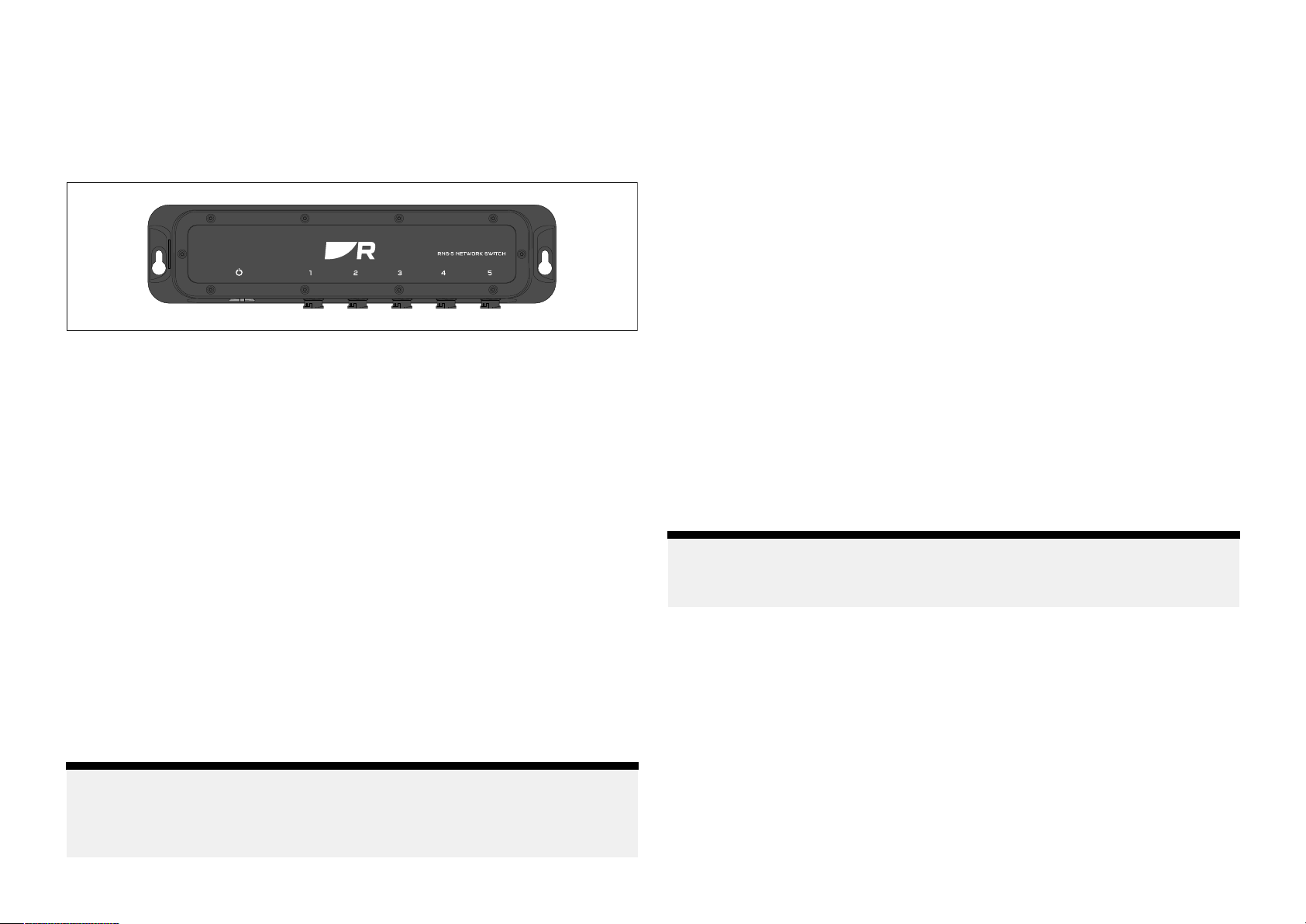
1Productoverview
3.2R
equiredadditionalcomponents
TheRaymarine®RNS-5networkswitchenablesyoutoconnectandshare
databetweenmultipledevicesfeaturingaRayNetconnector(orRJ45/
SeaT alkhs®connectorviaadaptercables),atuptospeedsofoneGigabit
persecond.
Thenetworkswitchhasthefollowingk eyfeatures:
•5xethernetports,usingwaterproofRayNetconnectors.
•Eachportcantransferdataatthefollowingspeeds:10/100/1000Mbits/s.
•Multipleswitchescanbeconnectedtogetherina“daisychain”for
expandedsystems.
•Ruggedenclosure—waterprooftoIPx6andIPx7standard.
•IgnitionprotectiontoENISO8846:2017standard.
•StatusandspeedLEDindicatorsforeachport.
•Compatiblewithdevicesfeaturinganyofthefollowingconnectors:
–RayNet.
–RJ45(SeaTalkhs®),viaadaptercables.
–RJ45,viaadaptercables.
•Examplesofdevicesthatcanbenetworkedtogetherinclude:
–Radarscanner.
–Sonarmodule.
–Thermalcamera.
–Multifunctiondisplay.
Networkswitchesmustbeusedinconjunctionwiththefollowingitems,
availableseparatelyfromRaymarine®
Networkcables
Forinformationonthecablesthataresuitableforyourproduct,refertothe
followingsection:p.29—Networkconnections
Cableextensions
Someinstallationsmayalsorequireextensionstonetworkorpowercables.
Forfurtherinformationoncableextensions,refertothefollowingsections:
•p.29—Networkconnections
•p.32—Powerconnections
•p.47—Sparesandaccessories
3.3Typicalsystem
Thefollowingexampleprovidesanoverviewofatypicalsystem,including
theavailableconnectionsandthetypesofdevicesthatcanbeconnectedto
yournetworkswitch.
Note:
Thissystemisshownasanexampleonlyandmaydifferfromyourplanned
installation.
Note:
ConnectionstoequipmentwithRJ45orSea Talkhs®connectorsmustbe
madeviaadaptercables.Forsuitableadaptercables,refertothefollowing
section:p.50—RayNettoRJ45adaptercables
Productandsystemoverview
13
Page 14
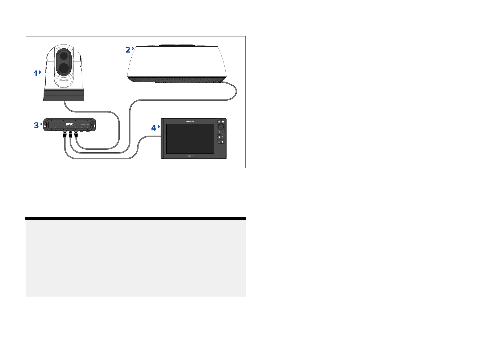
Example:typicalsystem
1.Thermalcamera.
2.R adarscanner .
3.RNS-5NetworkSwitch.
3.4Compatiblenetworkdevices
Y
ournetworkswitchiscompatiblewiththefollowingnetworkdevices:
•AnyRaymarine®productsfeaturingRayNetconnectorscanbeconnected
tothenetworkswitchviatheuseofaRayNettoRayNetnetworkcable.
•AnyRaymarine®productsfeaturingRJ45(SeaT alkhs®)connectorscan
beconnectedtothenetworkswitchviatheuseofaRayNettoRJ45
(SeaT alkhs®)networkadaptercable.
•AnyRaymarine®/non-Raymarine®productfeaturinganRJ45connector
canbeconnectedtothenetworkswitchviatheuseofaRayNettoRJ45
networkadaptercable.
4.Multifunctiondisplay.
Note:
Forinformationonhowtoconnectyourproducts,refertothefollowing
sections:
•p .24—Cablesandconnections—Generalinformation
•p.29—Networkconnections
•p.32—Powerconnections
Forinformationontheavailablecablesandaccessories,refertothe
followingsection:p.47—Sparesandaccessories
14
Page 15

CHAPTER4:P
CHAPTERCONTENTS
ARTSSUPPLIED
•4.
1Partssupplied—page16
•4.2Inlinefuserequirement—page16
P artssupplied
15
Page 16
4.
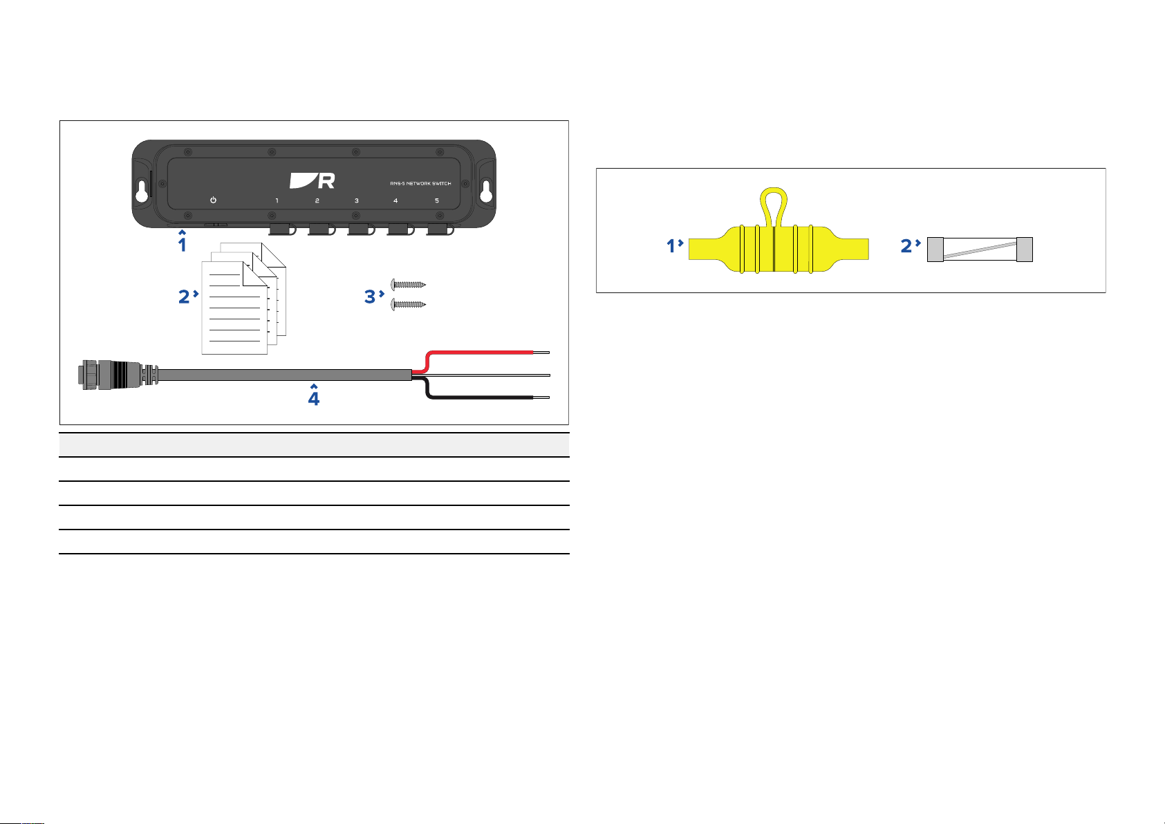
1Partssupplied
4.2Inlinefuserequirement
Listofpartssuppliedinthebox.
Item
1
2
DescriptionQuantity
RNS-5NetworkS witch
Documentationpack1
Y
ourproductrequiresasuitably-ratedinlinefusetobefittedtotheredpower
wire,housedinawaterprooffuseholder.Thisfuseanditsfuseholderare
NOTsuppliedwithyourproduct,andmustbeobtainedseparately,froma
marineorelectricalretailer.
1.Waterprooffuseholder .
2.Suitably-ratedinlinefuse.
Fuseratings
•Voltagerating—mustbeequaltoorgreaterthanthevoltageofyour
vessel’spowersupply.
•Currentrating—refertotheappropriatePowerconnectionsectionofthis
documentforfurtherdetails.
1
3
4
16
Fixingscrews(M4,8.94x25mm)
P owercable(1.5m(4.9ft))
2
1
Page 17

CHAPTER5:PRODUCTDIMENSIONS
CHAPTERCONTENT
•5.
S
1Productdimensions—page18
Productdimensions
17
Page 18
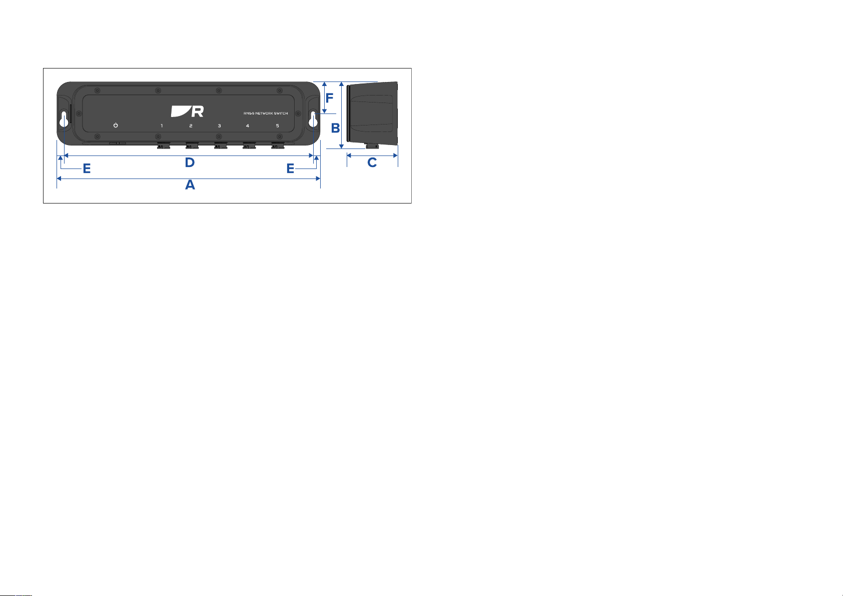
5.
1Productdimensions
•A=286.00mm(11.26in).
•B=72.65mm(2.86in).
•C=55.50mm(2.
•D=270.70mm(10.66in).
•E=7 .65mm(0.30in).
•F=34.33mm(1.35in).
19in).
18
Page 19

CHAPTER6:L
CHAPTERCONTENTS
OCATIONREQUIREMENTS
•6.
1Warningsandcautions—page20
•6.2Generallocationrequirements—page20
•6.3IgnitionProtection—page20
•6.4EMCinstallationguidelines—page20
•6.5Connectionstootherequipment—page21
•6.6Compasssafedistance—page21
L ocationrequirements
19
Page 20

6.
1Warningsandcautions
6.3IgnitionProtection
Important:
Beforeproceeding,ensurethatyouhavereadandunderstoodthe
warningsandcautionsprovidedinthep
ofthisdocument.
.7—Importantinformationsection
6.2Generallocationrequirements
Whenselectingalocationforyourproductitisimportanttoconsidera
numberoffactors.
K
eyfactorswhichcanaffectproductperformanceare:
•Ventilation—Toensureadequateairflow:
–Ensurethatproductismountedinacompartmentofsuitablesize.
–Ensurethatventilationholesarenotobstructed.Allowadequate
separationofallequipment.
Anyspecificrequirementsforeachsystemcomponentareprovidedlater
inthischapter.
•Mountingsurface—Ensureproductisadequatelysupportedonasecure
surface.Donotmountunitsorcutholesinplaceswhichmaydamage
thestructureofthevessel.
•Cabling—Ensuretheproductismountedinalocationwhichallowsproper
routing,supportandconnectionofcables:
–Minimumbendradiusof100mm(3.94in)unlessotherwisestated.
–Usecableclipstopreventstressonconnectors.
–Ifyourinstallationrequiresmultipleferritestobeaddedtoacablethen
additionalcableclipsshouldbeusedtoensuretheextraweightofthe
cableissupported.
•Wateringress—Theproductissuitableformountingbothaboveand
belowdecks.Althoughtheunitiswaterproof,itisgoodpracticetolocate
itinaprotectedareaawayfromprolongedanddirectexposuretorain
andsaltspray.
•Electricalinterference—Selectalocationthatisfarenoughawayfrom
devicesthatmaycauseinterference,suchasmotors,generatorsandradio
transmitters/receivers.
•Powersupply—Selectalocationthatisascloseaspossibletothe
vessel’sDCpowersource.Thiswillhelptokeepcablerunstoaminimum.
ThisproductiscertifiedtotheENISO8846:2017IgnitionProtectionstandard.
6.4EMCinstallationguidelines
Raymarine®equipmentandaccessoriesconformtotheappropriate
ElectromagneticCompatibility(EMC)regulations,tominimizeelectromagnetic
interferencebetweenequipmentandminimizetheeffectsuchinterference
couldhaveontheperformanceofyoursystem.
CorrectinstallationisrequiredtoensurethatEMCperformanceisnot
compromised.
Note:
InareasofextremeEMCinterference,someslightinterferencemaybe
noticedontheproduct.Wherethisoccurstheproductandthesourceof
theinterferenceshouldbeseparatedbyagreaterdistance.
ForoptimumEMCperformancewerecommendthatwhereverpossible:
•Raymarine®equipmentandcablesconnectedtoitare:
–Atleast1m(3.3ft)fromanyequipmenttransmittingorcablescarrying
radiosignalse.g.VHFradios,cablesandantennas.InthecaseofSSB
radios,thedistanceshouldbeincreasedto2m(6.6ft).
–Morethan2m(6.6ft)fromthepathofaradarbeam.Aradarbeam
cannormallybeassumedtospread20degreesaboveandbelowthe
radiatingelement.
•Theproductissuppliedfromaseparatebatteryfromthatusedforengine
start.Thisisimportanttopreventerraticbehavioranddatalosswhichcan
occuriftheenginestartdoesnothaveaseparatebattery.
•Raymarine®specifiedcablesareused.
•Cablesarenotcutorextended,unlessdoingsoisdetailedinthe
installationmanual.
Note:
Whereconstraintsontheinstallationpreventanyoftheabove
recommendations,alwaysensurethemaximumpossibleseparation
betweendifferentitemsofelectricalequipment,toprovidethebest
conditionsforEMCperformancethroughouttheinstallation.
20
Page 21

6.5Connectionstootherequipment
R
equirementforferritesonnon-Raymarinecables:
IfyourRaymarineequipmentistobeconnectedtootherequipmentusing
acablenotsuppliedbyRaymarine,asuppressionferriteMUSTalwaysbe
attachedtothecableneartheRaymarineunit.
6.6Compasssafedistance
Whenchoosingasuitablelocationforyourproductyoushouldaimto
maintainthemaximumpossibledistancebetweentheproductandany
installedcompass.Thisdistanceshouldbeatleast1m(3ft)inalldirections.
Forsmallervesselsitmaynotbepossibletoachievethisdistance.Inthis
situationensurethatthecompassisnotaffectedbytheproductwhenitis
poweredon.
L ocationrequirements
21
Page 22

CHAPTER7:MOUNTING
CHAPTERCONTENT
•7
.1T oolsrequired—page23
S
•7.2Mountingtheunit—page23
22
Page 23
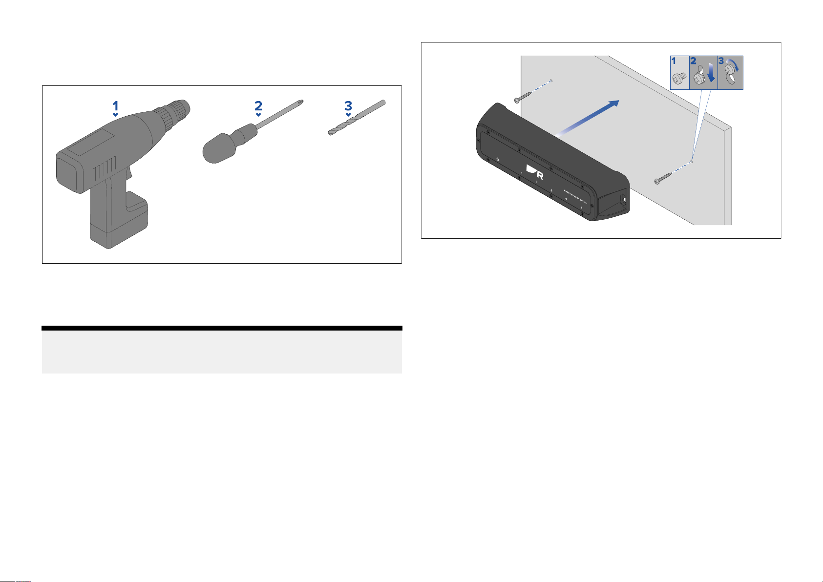
7
.1Toolsrequired
Productinstallationrequiresthefollowingtools:
1.P owerdrill
2.Pozidrivescrewdriver
3.Drillbit
Note:
Theappropriatedrillbitsizeisdependentonthethicknessandmaterialof
themountingsurface .
1.Preparethemountingsurface:
i.Fixthesuppliedmountingtemplatetothechosenlocation,using
maskingorself-adhesivetape.
ii.Drill2holesasindicatedonthetemplatetoacceptthefixings.
iii.Removethemountingtemplate.
iv.Screwthefixingsapproximatelyhalfwayintotheholesinthe
mountingsurface.
2.Placetheunitoverthefixingsscrewsandpushdowntoengagethe
keyholeslots.
3.Fullytightenthescrews.
7 .2Mountingtheunit
Followtheinstructionsbelowtomounttheunit.
Beforemountingtheproduct,ensurethatyouhave:
•Selectedasuitablelocation,basedonthelocationrequirementsfoundin
thisdocument.
•Identifiedtherelevantcableconnectionsandtheroutethatthecables
willtake.
Mounting
23
Page 24

CHAPTER8:C
CHAPTERCONTENTS
ABLESANDCONNECTIONS—GENERALINFORMATION
•8.
1Generalcablingguidance—page25
•8.2Typicalsystem—page26
•8.3Expandedsystem—page27
•8.4Multipleswitches—page27
•8.5Networkcableconnectortypes—page28
•8.6Sea T alk
hs
—page28
•8.7Connectionsoverview—page28
24
Page 25
8.
1Generalcablingguidance
Cabletypesandlength
Itisimportanttousecablesoftheappropriatetypeandlength.
•UnlessotherwisestatedonlyusecablessuppliedbyRaymarine.
•Whereitisnecessarytousenon-Raymarinecables,ensurethattheyareof
correctqualityandgaugefortheirintendedpurpose.(e.g.:longerpower
cablerunsmayrequirelargerwiregaugestominimizevoltagedropalong
therun).
•DoNOTruncablesneartoenginesorfluorescentlights.
•Alwaysroutedatacablesasfarawayaspossiblefrom:
–Otherequipmentandcables.
–HighcurrentcarryingACandDCpowerlines.
–Antennas.
Strainrelief
Useadequatestrainreliefforcablingtoensurethatconnectorsareprotected
fromstrainandwillnotpulloutunderextremeseaconditions.
Cablerouting
Cablesmustberoutedcorrectly,tomaximizeperformanceandprolong
cablelife.
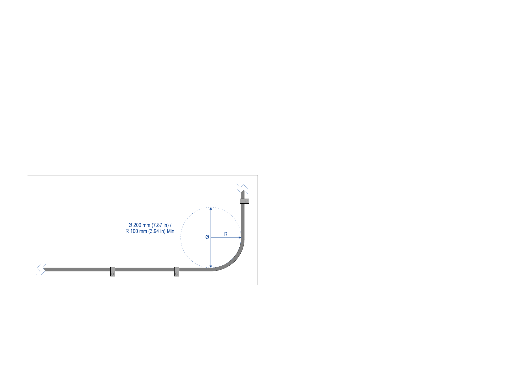
•DoNOTbendcablesexcessively.Whereverpossible,ensureaminimum
benddiameter(Ø)of200mm(7.87in)/minimumbendradius(R)of
100mm(3.94in).
•Protectallcablesfromphysicaldamageande xposuretoheat.Use
trunkingorconduitwherepossible.DoNOTruncablesthroughbilgesor
doorways,orclosetomovingorhotobjects.
•Securecablesinplaceusingcableclipsorcableties.Coilanyexcess
cableandtieitoutoftheway.
•Whereacablepassesthroughanexposedbulkheadordeckhead,use
asuitablewatertightfeed-through.
Circuitisolation
AppropriatecircuitisolationisrequiredforinstallationsusingbothACand
DCcurrent:
•Alwaysuseisolatingtransformersoraseparatepower-invertertorunPC’s,
processors,displaysandothersensitiveelectronicinstrumentsordevices.
•AlwaysuseanisolatingtransformerwithWeatherFAXaudiocables.
•Alwaysuseanisolatedpowersupplywhenusinga3rdpartyaudio
amplifier.
•AlwaysuseanRS232/NMEAconverterwithopticalisolationonthesignal
lines.
•AlwaysmakesurethatPC’sorothersensitiveelectronicdeviceshave
adedicatedpowercircuit.
Cableshielding
Ensurethatcableshieldingisnotdamagedduringinstallationandthatall
cablesareproperlyshielded.
Suppressionferrites
•Raymarine®cablesmaybepre-fittedorsuppliedwithsuppressionferrites.
TheseareimportantforcorrectEMCperformance.Ifferritesaresupplied
separatelytothecables(i.e.notpre-fitted),youmustfitthesupplied
ferrites,usingthesuppliedinstructions.
•Ifaferritehastoberemovedforanypurpose(e.g.installationor
maintenance),itmustbereplacedintheoriginalpositionbeforethe
productisused.
Cablesandconnections—Generalinformation25
Page 26
•Useonlyferritesofthecorrecttype
authorizeddealers.
•Whereaninstallationrequiresmultipleferritestobeaddedtoacable,
additionalcableclipsshouldbeusedtopreventstressontheconnectors
duetotheextraweightofthecable.
arning:Positivegroundsystems
W
Donotconnectthisunittoasystemwhichhaspositive
grounding.
,suppliedbyRaymarine®orits
Connectingcables
Followthestepsbelowtoconnectthecable(s)toyourproduct.
1.Ensurethatthevessel'
2.Ensurethatthedevicebeingconnectedhasbeeninstalledinaccordance
withtheinstallationinstructionssuppliedwiththatdevice.
3.Ensuringcorrectorientation,pushcableconnectorsfullyontothe
correspondingconnectors.
4.Engageanylockingmechanismtoensureasecureconnection(e.g.:turn
lockingcollarsclockwiseuntiltight,orinthelockedposition).
5.Ensureanybareendedwireconnectionsaresuitablyinsulatedtoprevent
shortingandcorrosionduetowateringress.
spowersupplyisswitchedoff.
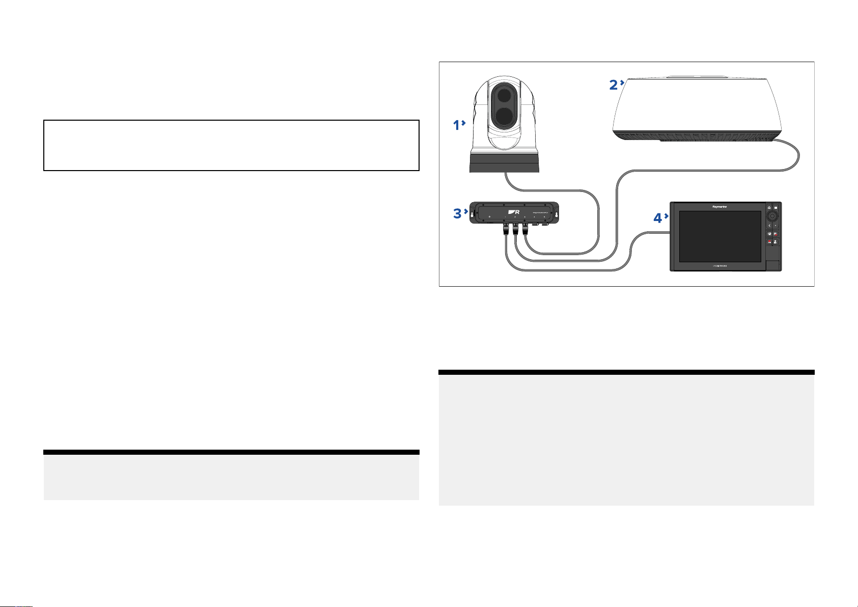
Example:typicalsystem
1.Thermalcamera.
2.Radarscanner.
3.RNS-5NetworkSwitch.
4.Multifunctiondisplay.
8.2Typicalsystem
Thefollowingexampleprovidesanoverviewofatypicalsystem,including
theavailableconnectionsandthetypesofdevicesthatcanbeconnectedto
yournetworkswitch.
Note:
Thissystemisshownasane xampleonlyandmaydifferfromyourplanned
installation.
26
Note:
Forinformationonhowtoconnectyourproducts,refertothefollowing
sections:
•p.24—Cablesandconnections—Generalinformation
•p.29—Networkconnections
•p.32—Powerconnections
Forinformationontheavailablecablesandaccessories,refertothe
followingsection:p.47—Sparesandaccessories
Page 27
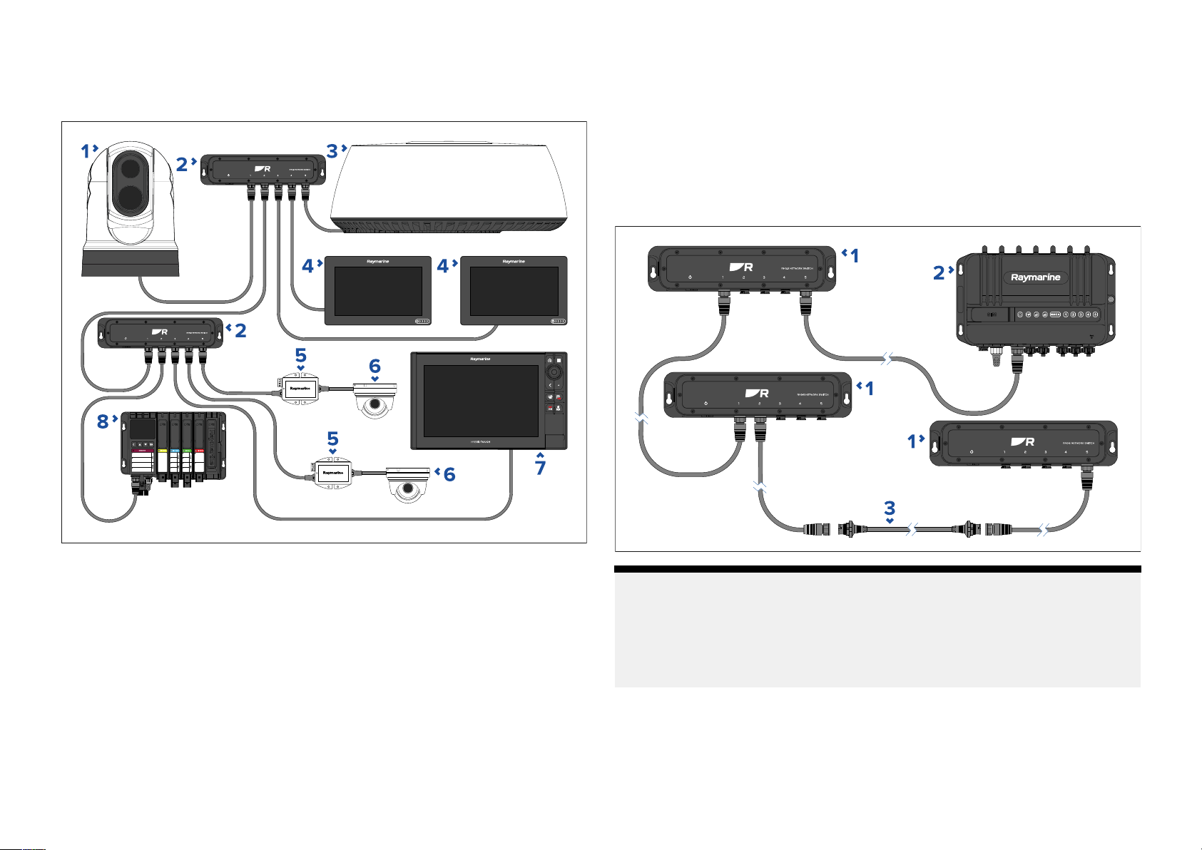
8.3Expandedsystem
8.4Multipleswitches
Example:e
xpandedsystem
Systemswithmorethan5deviceswillrequiremorethanonenetwork
switch.Networkswitchescanbeconnectedtogether(daisy-chained)for
thispurpose.
Thenetworkswitchcanbeconnected(daisy-chained)toanothernetwork
switchviaanyoftheconnectionports.
Example:daisy-chainconnectionscenario
1.Thermalcamera.
2.RNS-5NetworkS witch.
3.Radarscanner.
4.Multifunctiondisplay.
5.PoEInjector .
6.IPCamera.
7.Multifunctiondisplay.
8.Y achtSense™DigitalControlSystem.
Cablesandconnections—Generalinformation
Note:
Ifdaisy-chaining4ormorenetworkswitchestogetherwithinasystem,it
isrecommendedthatonenetworkswitchisusedasacentralconnection
point.Thiswillensurethatanyadverseeffectsduetoconnectionissues
(suchasfaultycablingorslowconnectionspeeds)areminimizedwithin
yoursystem.
1.RNS-5NetworkSwitch.
2.Y achtSense™LinkMarineRouter.
3.RayNet(male)toRayNet(male)adaptercable(A80162)(100mm(3.94in)).
Suitableforjoining(female)RayNetcablestogetherforlongercableruns.
27
Page 28
Forfurtherinformationonadditionalcablingoptions,refertothefollowing
section:p
.47—Sparesandaccessories
8.7Connectionsoverview
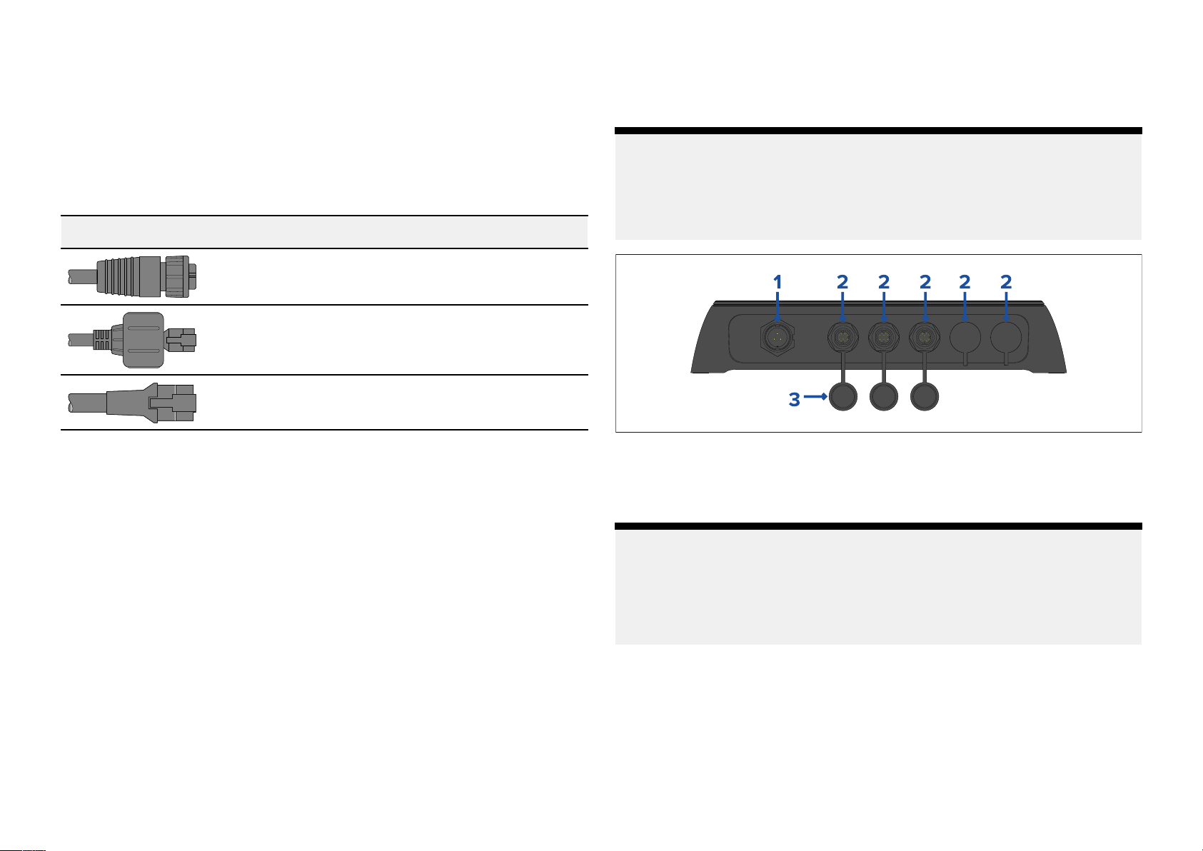
TheRNS-5networkswitchincludesthefollowingconnections:
8.5Networkcableconnectortypes
Thereare3typesofnetworkcableconnectors—RayNet,RJ45(Sea Talkhs®),
andRJ45.
Connector
8.6Sea Talk
SeaT alk
compatibleequipment(suchasdeviceswithaRayNetorRJ45SeaT alkhs®
connector)tocommunicaterapidlyandsharelargeamountsofdata.
InformationsharedviatheSeaT alk
•Sharedcartography(betweencompatibledisplays).
•Digitalradardata.
hs
isahighspeedethernetbasedmarinenetworkwhichallows
Description
RayNet
RJ45(SeaTalkhs®)forconnectionto(legacy)
RaymarineequipmentfeaturingaSeaT alkhs®
connector.
RJ45
hs
hs
networkincludes:
Note:
ThenetworkswitchissuppliedwithprotectivecapsfittedtotheR
connectionports.
Theprotectivecapsshouldremaininplaceuntilconnectionsaremade.Ifa
portisnotrequiredthentheprotectivecapshouldnotberemoved.
1.3-pinpowerconnectionport.
2.RayNetnetworkconnectionport(10/100/1000Mbits/s).
3.Protectivecap.
Note:
Forfurthernetworkorpowerconnectioninformation,refertothefollowing
sections:
•p.29—Networkconnections
•p.32—Powerconnections
ayNet
•Sonardata.
28
Page 29

CHAPTER9:NETW
CHAPTERCONTENTS
ORKCONNECTIONS
•9
•9.2RayNetcableconnections—page30
•9.3RJ45(SeaTalkhs®)cableconnections—page30
•9.4RJ45cableconnections—page31
•9.5Networkcableextensions—page31
.1Equipmentconnections—page30
Networkconnections29
Page 30
9
.1Equipmentconnections
EquipmentisconnectedtothenetworkswitchusingeitheraRayNetcableor
aRayNettoRJ45,orRJ45(Sea Talkhs®)adaptercable.
Thefollowingsectionprovidesexamplesof3differentconnectionscenarios
thatmaybeapplicablewhenconnectingyourequipmenttotheRNS-5
NetworkSwitch:
1.ConnectiontoequipmentfeaturingRayNetconnectors:
p.30—RayNetcableconnections
2.ConnectiontoequipmentfeaturingRJ45(SeaTalkhs®)connectors:
p.30—RJ45(SeaT alkhs®)cableconnections
3.ConnectiontoequipmentfeaturingRJ45connectors:
p.31—RJ45cableconnections
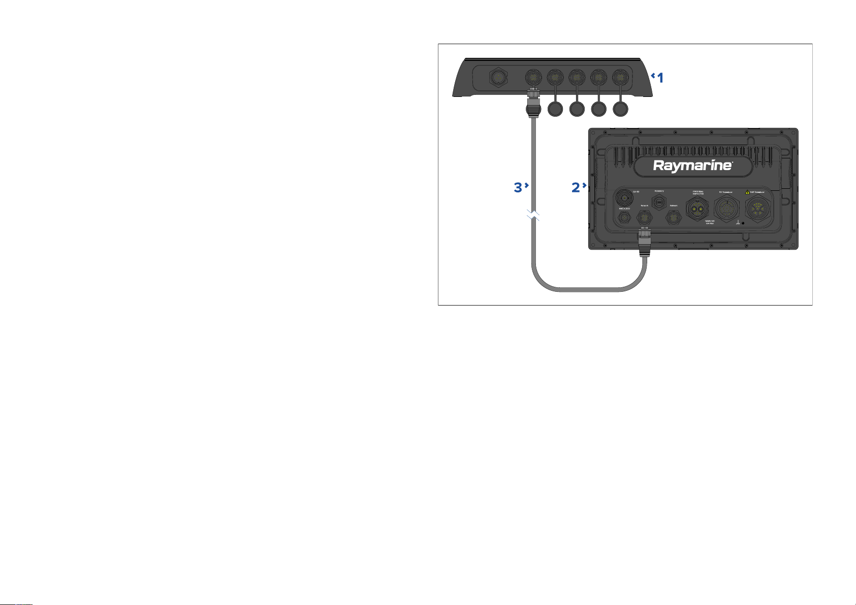
9.2RayNetcableconnections
ConnectingtheRNS-5networkswitchtoRaymarine®equipmentfeaturing
aRayNetconnector .
Requiredcabling/connectors:
•RayNet(female)toRayNet(female)cable(notsupplied).
Forfurtherinformationonthecablingrequired,refertothefollowingsection:
p.49—RayNettoRayNetcablesandconnectors
1.RNS-5networkswitch.
2.Raymarine®equipmentwithaRayNetconnector.
3.RayNet(female)toRayNet(female)networkcable(notsupplied).
Example:RayNetcableconnectionscenario
30
9.3RJ45(Sea Talkhs®)cableconnections
ConnectingtheRNS-5networkswitchtoRaymarine®equipmentfeaturinga
RJ45(Sea Talkhs®)connector .
Requiredcabling/connectors:
•RayNet(female)toRJ45(SeaT alkhs®)(male)adaptercable(notsupplied).
Forfurtherinformationonthecablingrequired,refertothefollowingsection:
p.50—RayNettoRJ45adaptercables
Example:RJ45(SeaT alkhs®)cableconnectionscenario
Page 31
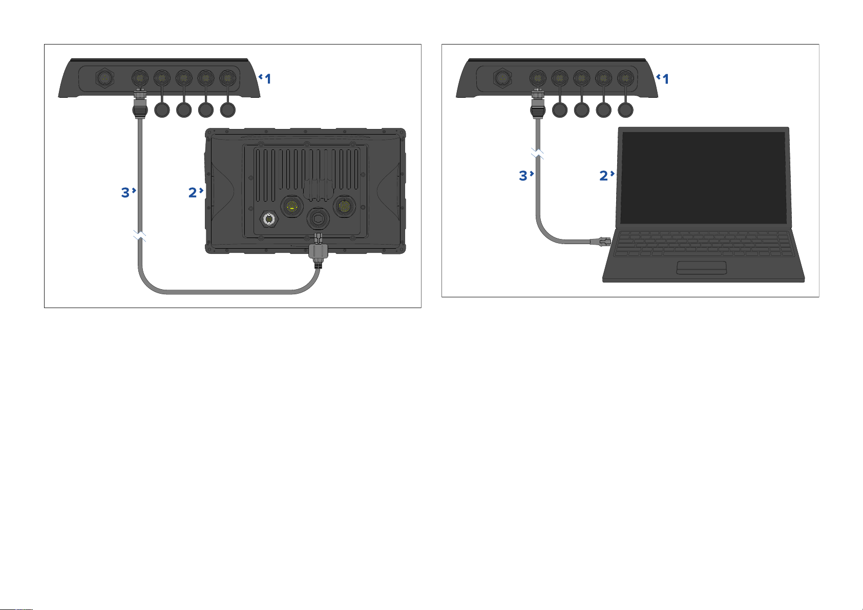
1.RNS-5networkswitch.
1.RNS-5networkswitch.
2.R aymarine®Sea T alkhs®equipmentfeaturinganRJ45(SeaTalkhs®)
connector,suchasC-SeriesWidescreen,E-SeriesWidescreen,G-Series
andE-SeriesClassicmultifunctiondisplays.
3.RayNet(female)toRJ45(Sea Talkhs®)waterproofplug(male)adapter
cable(notsupplied).
9.4RJ45cableconnections
ConnectingtheRNS-5networkswitchtoequipmentfeaturinganRJ45
connector.
Requiredcabling/connectors:
•RayNet(female)toRJ45(male)adaptercable(notsupplied).
Forfurtherinformationonthecablingrequired,refertothefollowingsection:
p.50—RayNettoRJ45adaptercables
Example:RJ45cableconnectionscenario
Networkconnections31
2.EquipmentfeaturinganRJ45connector,suchasaPCorlaptop.
3.RayNet(female)toRJ45plug(male)adaptercable(notsupplied).
9.5Networkcableextensions
Ifyouwishtoextendthelengthofanetworkcableconnectedtoyour
product,youcanrefertothefollowingsectionforfurtherinformation:
p.47—Sparesandaccessories
Page 32

CHAPTER10:PO
CHAPTERCONTENTS
WERCONNECTIONS
•10
•10.2Powerdistribution—page33
•10.3Powercableextension(12/24Vsystems)—page35
•10.4Powercabledrainwireconnection—page36
.1Powerconnection—page33
32
Page 33
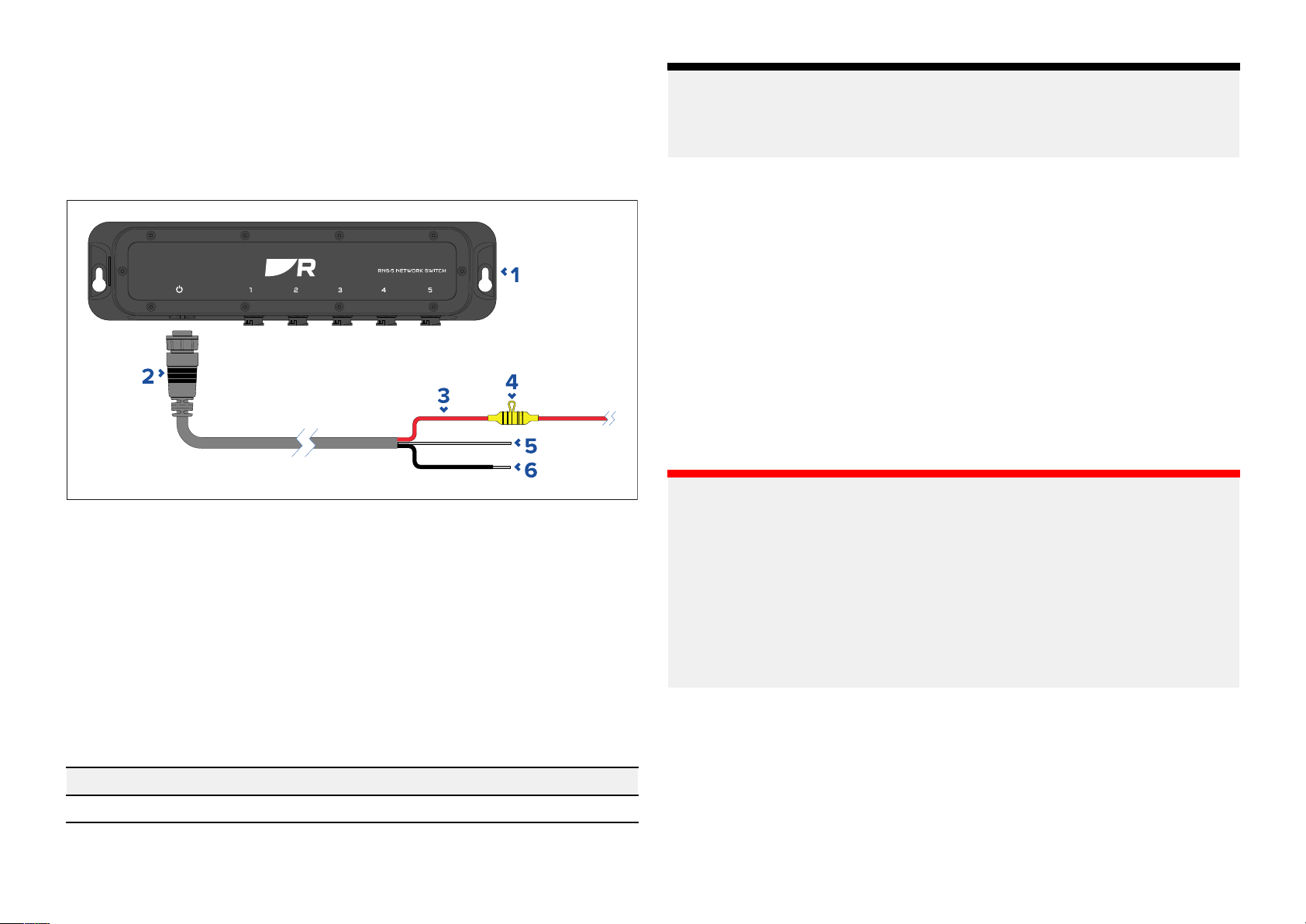
10
.1Powerconnection
Note:
Thepowerforthenetworkswitchisprovideddirectlybya12Vor24V
powersource.
Thenetworkswitchissuppliedwithapowercablewithbarestrippedwires,
suitablefordirectconnectiontoa12Vor24Vpowersupply:
1.RNS-5NetworkS witch.
2.1.5m(4.9ft)Powercable(supplied).
3.Redcable(positive)—connectstothepowersupply’spositiveterminal.
4.Waterprooffuseholdercontainingasuitably-ratedinlinefuse(not
supplied),whichmustbefittedtotheredpositivewire—refertothe
fuseratingsbelow.
5.Graywire(drain)—connectstothevesselRFground(ifavailable),orthe
negativebatteryterminal.
Thesuitablefuseratingforthethermalbreak
numberofdevicesyouareconnecting.Ifindoubtconsultanauthorized
Raymarinedealer.
.2Powerdistribution
10
Recommendationsandbestpracticeforthepowerconnectionofproducts
suppliedwithadrainwireaspartofthesuppliedpowercable.
•Theproductissuppliedwithapowercable,eitherasaseparateitemora
captivecablepermanentlyattachedtotheproduct.Onlyusethepower
cablesuppliedwiththeproduct.DoNOTuseapowercabledesignedfor,
orsuppliedwith,adifferentproduct.
•RefertothePowerconnectionsectionformoreinformationonhowto
identifythewiresinyourproduct’spowercable,andwheretoconnect
them.
•Seebelowformoreinformationonimplementationforsomecommon
powerdistributionscenarios:
Important:
•Whenplanningandwiring,takeintoconsiderationotherproductsin
yoursystem,someofwhich(e.g.sonarmodules)mayplacelargepower
demandpeaksonthevessel’selectricalsystem,whichmayimpactthe
voltageavailabletootherproductsduringthepeaks.
•Theinformationprovidedbelowisforguidanceonly,tohelpprotect
yourproduct.Itcoverscommonvesselpowerarrangements,butdoes
NOTcovereveryscenario.Ifyouareunsurehowtoprovidethecorrect
levelofprotection,pleaseconsultanauthorizeddealerorasuitably
qualifiedprofessionalmarineelectrician.
erisdependentonthe
6.Blackwire(negative)—connectstothepowersupply’snegativeterminal.
Fuseratings
InlinefuseratingThermalbreak errating
2A3A
P owerconnections33
Page 34
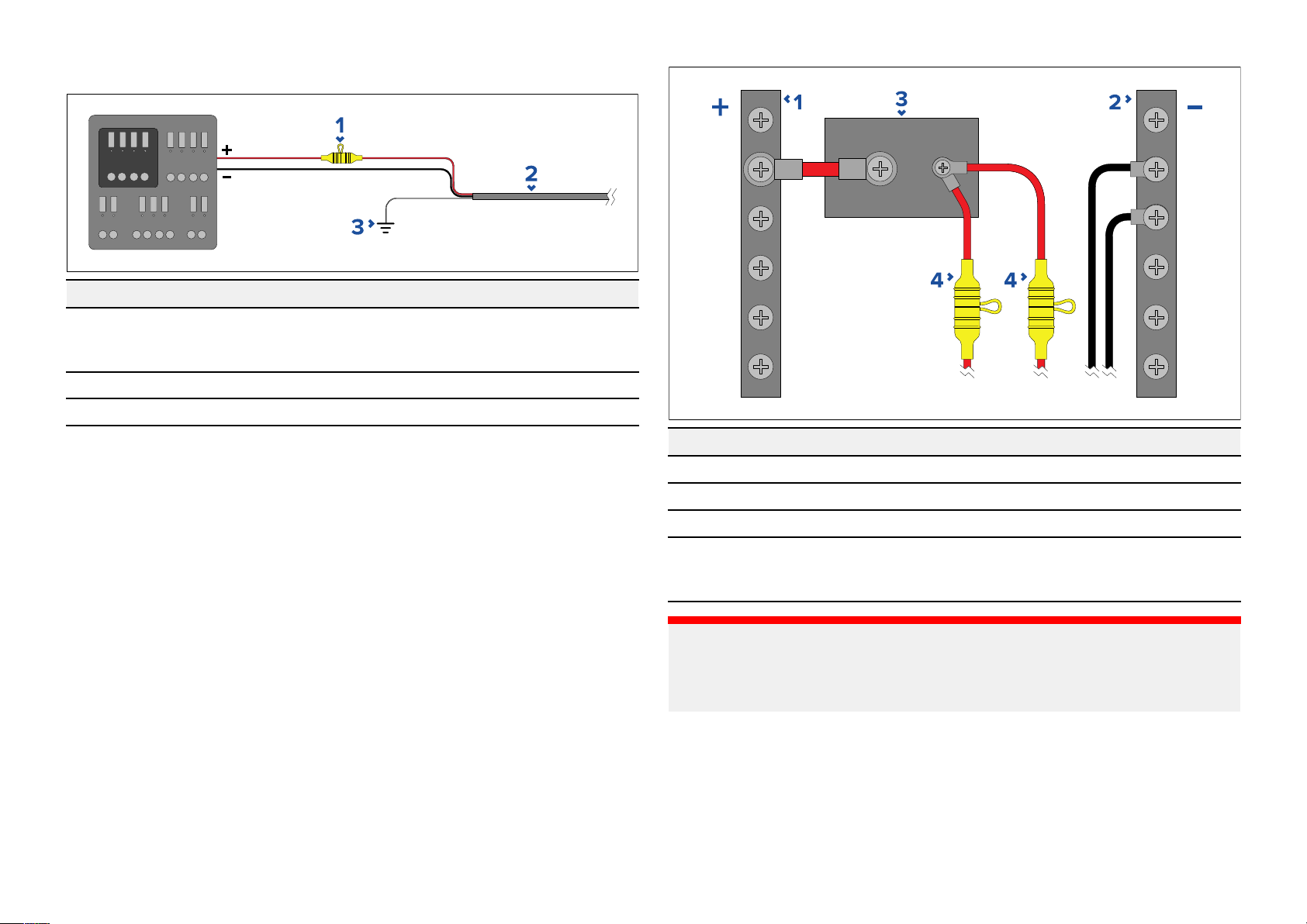
Implementation—connectiontodistributionpanel(R
ecommended)
Item
1
Description
W aterprooffuseholdercontainingasuitably-ratedinlinefuse
mustbefitted.Forsuitablefuserating,referto:Inlinefuseand
thermalbreakerratings.
2
3
Productpowercable .
Drainwireconnectionpoint.
•Itisrecommendedthatthesuppliedpowercableisconnectedtoasuitable
break erorswitchonthevessel'sdistributionpanelorfactory-fittedpower
distributionpoint.
•Thedistributionpointshouldbefedfromthevessel’sprimarypower
sourceby8AWG(8.36mm
2
)cable.
•Ideally,allequipmentshouldbewiredtoindividualsuitably-ratedthermal
breakersorfuses,withappropriatecircuitprotection.Wherethisis
notpossibleandmorethan1itemofequipmentsharesabreaker ,use
individualinlinefusesforeachpowercircuittoprovidethenecessary
protection.
Item
1
2
Description
Positive(+)bar
Negative(-)bar
3Circuitbreaker
4
Waterprooffuseholdercontainingasuitably-ratedinlinefuse
mustbefitted.Forsuitablefuserating,referto:Inlinefuseand
thermalbreakerratings.
Important:
Observetherecommendedfuse/breakerratingsprovidedintheproduct’s
documentation,howeverbeawarethatthesuitablefuse/breakerratingis
dependentonthenumberofdevicesbeingconnected.
Implementation—directconnectiontobattery
•Whereconnectiontoapowerdistributionpanelisnotpossible,thepower
cablesuppliedwithyourproductmaybeconnecteddirectlytothevessel's
battery,viaasuitablyratedfuseorbreaker.
•Thepowercablesuppliedwithyourproductincludesaseparatedrain
wire,whichmustbeconnectedtothevessel’scommonRFground(if
34
Page 35
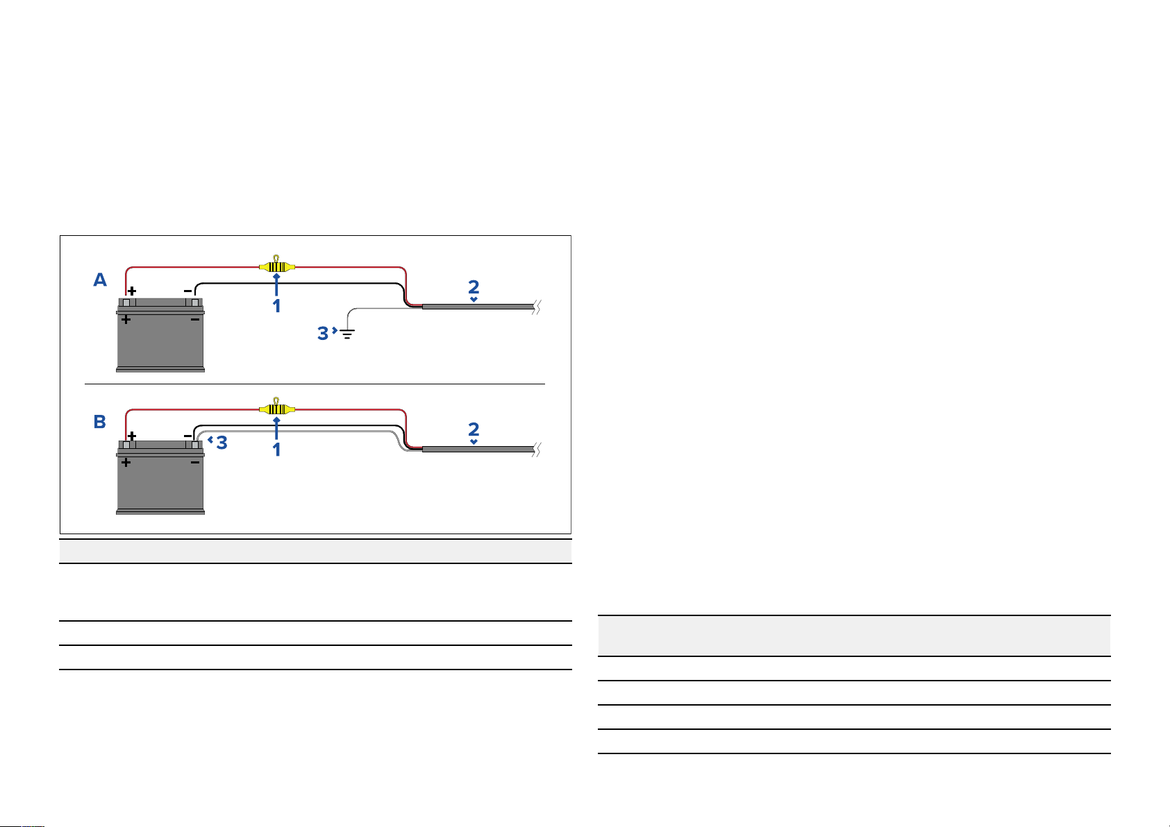
available),orthebattery’
snegativeterminal.Formoreinformation,refer
to:p.36—Powercabledrainwireconnection
•IfthepowercableisNOTsuppliedwithafittedinlinefuse,youMUSTfit
asuitablyratedfuseorbreakerbetweentheredwireandthebattery’s
positiveterminal.
•Refertotheinlinefuseratingsprovidedintheproduct’sdocumentation.
•Ifyouneedtoextendthelengthofthepowercablesuppliedwithyour
product,ensureyouobservethededicatedPowercableextensionsadvice
providedintheproduct’sdocumentation.
Suitableforavesselwithoutacommongroundingpoint.Inthiscase,the
powercable’sdrainwireshouldbeconnecteddirectlytothebattery’s
negativeterminal.
Grounding
Ensurethatyouobserveanyadditionalgroundingadviceprovidedinthe
product’sdocumentation.
Moreinformation
Itisrecommendedthatbestpracticeisobservedinallvesselelectrical
installations,asdetailedinthefollowingstandards:
•BMEACodeofPracticeforElectricalandElectronicInstallationsinBoats
•NMEA0400InstallationStandard
•ABYCE-11AC&DCElectricalSystemsonBoats
•ABYCA-31BatterychargersandInverters
•ABYCTE-4LightningProtection
10.3Powercableextension(12/24Vsystems)
Ifyouneedtoextendthelengthofthepowercablesuppliedwithyour
product,ensureyouobservethefollowingadvice:
•Thepowercableforeachunitinyoursystemshouldberunasaseparate,
singlelengthof2-wirecablefromtheunittothevessel'sbatteryor
Item
1
Description
W aterprooffuseholdercontainingasuitably-ratedinlinefuse
mustbefitted.Forsuitablefuserating,referto:Inlinefuseand
thermalbreakerratings.
2
3
Productpowercable .
Drainwireconnectionpoint.
BatteryconnectionscenarioA:
SuitableforavesselwithacommonRFgroundpoint.Inthisscenario ,the
powercable’sdrainwireshouldbeconnectedtothevessel’scommon
groundpoint.
distributionpanel.
•Ensurethattheextensioncableisofasufficientgaugeforthesupply
voltageandthetotalloadofthedeviceandthelengthofthecablerun.
Refertothefollowingtablefortypicalminimumpowercablewiregauges:
Cablelengthinmeters
(feet)
<8(<25)16(1.31mm
16(50)14(2.08mm
24(75)14(2.08mm
>32(>100)14(2.08mm
WiregaugeinAWG
2
(mm
)for12Vsupply
2
)18(0.82mm
2
)18(0.82mm
2
)16(1.31mm
2
)16(1.31mm
WiregaugeinAWG
2
(mm
)for24Vsupply
2
)
2
)
2
)
2
)
BatteryconnectionscenarioB:
P owerconnections35
Page 36

Important:
Beawarethatsomeproductsinyoursystem(suchassonarmodules)
cancreatevoltagepeak
availabletootherproductsduringthepeaks.
Important:
T
oensurepowercables(includinganyextension)areofasufficientgauge,
ensurethatthereisacontinuousminimumvoltageof10.8Vdcattheend
ofthecablewhereitenterstheproduct’spowerconnector,evenwithafully
flatbatteryat11Vdc.(Donotassumethataflatbatteryisat0Vdc.Dueto
thedischargeprofileandinternalchemistryofbatteries,thecurrentdrops
muchfasterthanthevoltage.A“fullyflat”batterystillshowsapositive
voltage,evenifitdoesn’thaveenoughcurrenttopoweryourdevice.)
satcertaintimes,whichmayimpactthevoltage
10 .4Powercabledrainwireconnection
Thepowercablesuppliedwiththisproductincludesadedicateddrainwire
forconnectiontoavessel'sRFgroundpoint(ifavailable),orthenegative
batteryterminal.
ItisimportantthataneffectiveRFgroundisconnectedtothesystem.Asingle
commongroundpointshouldbeusedforallequipment.Ifseveralitems
requiregrounding,eachitemofequipmentcanbegroundedbyconnecting
thedrainwireofthepowercablefirsttoasinglelocalpoint(e.g.withina
distributionpanel),andthenthispointconnectedviaanappropriately-rated
conductortothevessel'sRFcommongroundpoint.AnRFgroundpointis
typicallyacircuitwithaverylow-impedancesignalatRadioFrequency(RF),
connectedtotheseaviaanelectrodeimmersedintheseaorbondedtothe
innersideofthehullinanareathatisunderwater.
OnvesselswithoutanRFgroundsystem,thedrainwiresofallequipment
shouldbeconnecteddirectlytothevessel’snegativebatteryterminal.
Thedcpowersystemshouldbeeither:
•Negativegrounded(“bonded”),withthenegativebatteryterminal
connectedtothevessel'sRFground.
•Floating,withneitherbatteryterminalconnectedtothevessel'sground.
Thepreferredminimumrequirementforthepathtoground(bondedor
non-bonded)isviaaflattinnedcopperbraid,witha30Aratingorgreater .
Ifthisisnotpossible,anequivalentstrandedwireconductormaybeused,
ratedasfollows:
•forrunsof<1m(3ft),use6mm2(10AWG)orgreater .
•forrunsof>1m(3ft),use8mm2(8AWG)orgreater.
Inanygroundingsystem,alwayskeepthelengthofconnectingbraidor
wiresasshortaspossible.
36
Page 37

CHAPTER11:TROUBLESHOO
CHAPTERCONTENTS
TING
•11.
1Troubleshooting—page38
•11.2Poweruptroubleshooting—page38
•11.3LEDdiagnostics—page38
T roubleshooting
37
Page 38
11.
1Troubleshooting
Thetroubleshootingsectionprovidespossiblecausesandthecorrective
actionrequiredforcommonproblemsthatareassociatedwiththeinstallation
andoperationofyourproduct.
Beforepackingandshipping,allRaymarine®productsaresubjectedto
comprehensivetestingandqualityassuranceprograms.Ifyoudoexperience
problemswithyourproduct,thissectionwillhelpyoutodiagnoseandcorrect
problemstorestorenormaloperation.
Ifafterreferringtothissectionyouarestillhavingproblemswithyour
product,pleaserefertotheT echnicalsupportsectionofthismanualfor
usefullinksandRaymarine®ProductSupportcontactdetails.
4.Checkthevessel’sbatteryvoltage,theconditionofthebatteryterminals
andpowersupplycables,ensuringconnectionsaresecure,cleanand
freefromcorrosion;replaceifnecessary.
Incorrectpowerconnection
Thepowersupplymaybewiredincorrectly
instructionshavebeenfollowed.
Powersourceinsufficient
Checkthatyourpowersupply(batteryordistributionpanel)isprovidinga
minimumof10
.8Vtoeachcomponentinthesystem.
,ensuretheinstallation
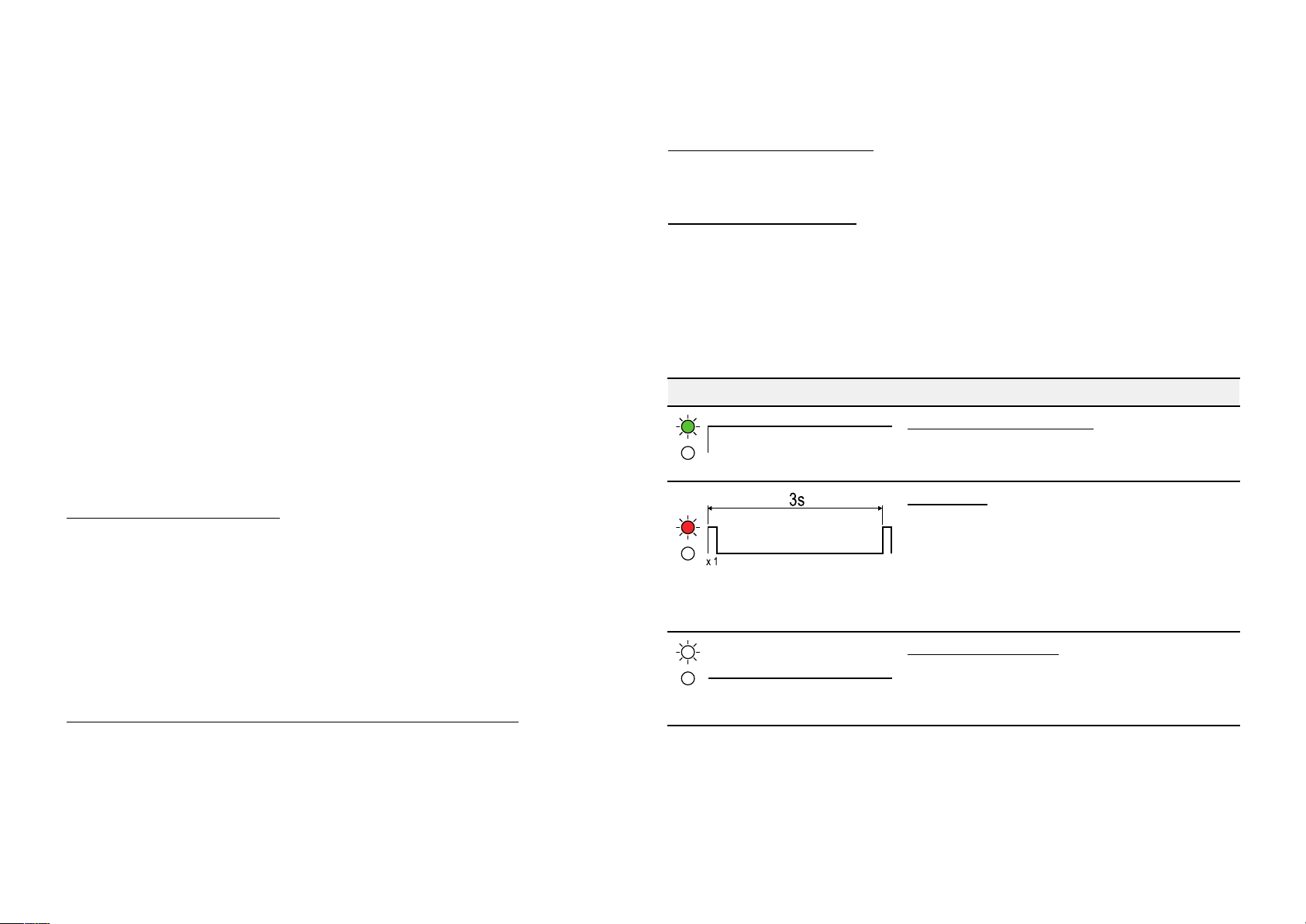
11.3LEDdiagnostics
11.2Poweruptroubleshooting
Beforetroubleshootingproblemswithyourpowerconnection,ensurethat
youhavefollowedthepowerconnectionguidanceprovidedintheproduct’s
installationinstructionsandperformedapowercycle/rebootofthedevice.
Thetroubleshootinginformationbelowcanbeusedifyouareexperiencing
problemswithpoweringupyourproduct.
Blownfuse/trippedbreaker
1.Checkthefuse ,locatedinlinewiththepowercable.Ensurethatithas
thecorrectrating(refertoConnectionschapter),asanunder-ratedfuse
canaffectthepowersuppliedtotheproduct.Ifthefusehasblown,
replacewithanewfuse.
2.Checktheconditionofrelevant/additionalfusesandbreakersand
connections;replaceifnecessary.
3.Iffusekeepsblowing,checkforcabledamage,brokenconnectorpins
orincorrectwiring.
Poor/damaged/insecurepowersupplycable/connections
1.Checkthatthepowercableconnectorisfullyinsertedintotheunitand
lock edinposition.
2.Checkthepowersupplycableandconnectorsforsignsofdamageor
corrosion,replaceifnecessary.
PowerportLED
LEDIndicationLEDStatusandrequiredaction
(Green)Poweredup/Ok
•Normaloperation—nouseractionis
required.
(Red)Fault
•Considercontactingyourlocaldealer
orRaymarine®ProductSupport.For
Raymarine®ProductSupportcontact
details,refertothefollowingsection:
p.43—Raymarineproductsupportand
servicing
(Nocolor)Nopower
•Refertotheadvicefound
withinthefollowingsection:
p.38—Poweruptroubleshooting
3.Withtheunitturnedon,tryflexingthepowercableneartotheconnector
toseeifthiscausestheunittore-boot/losepower;replaceifnecessary.
38
Page 39
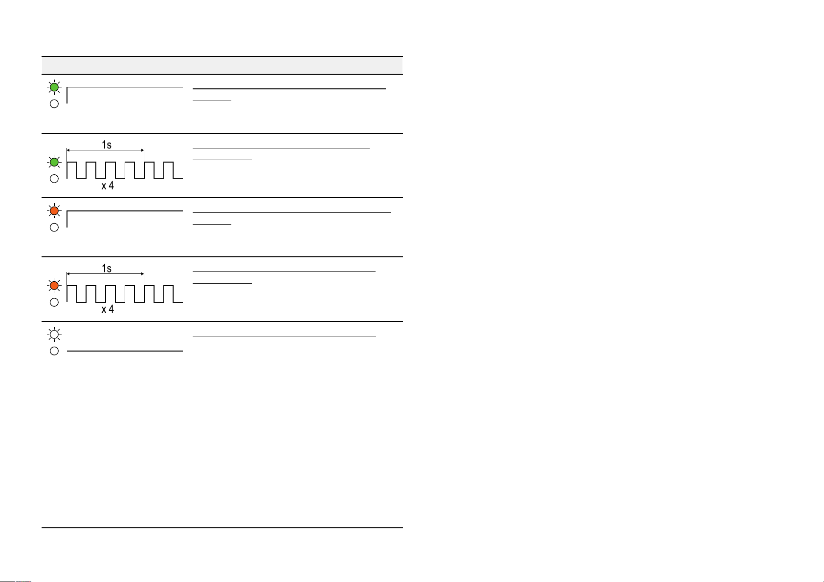
ortspeed/activityLEDs(1/2/3/4/5)
P
LEDIndicationLEDS
(Green)1,000Mbits/sEthernetActive(no
transfer)
•Normaloperation—nouseractionis
(Green)1,000Mbits/sEthernetActive
(transferring)
•Normaloperation—nouseractionis
(Amber)10/100Mbits/sEthernetActive(no
transfer)
•Normaloperation—nouseractionis
(Amber)10/100Mbits/sEthernetActive
(transferring)
•Normaloperation—nouseractionis
(Nocolor)Nonetworkactivitydetected
•Checkthecableconnectionfortheport.
tatusandrequiredaction
required.
required.
required.
required.
•Checkanyadditionalconnections.
•Checkthattheunitconnectedtothe
switchispoweredon.
•Checkthattheunitconnectedtothe
switchiscurrentlytransferringdata.
Thiscanbeconfirmedbyperformingan
actiononthemultifunctiondisplaythat
willinitiatedatatransferfortherelevant
unit—forexample,ifyoususpecta
problemwiththeportcorrespondingto
aconnectedradarscanner ,rangeinor
outintheradarapplicationtoinitiatedata
activity.
T roubleshooting
39
Page 40

CHAPTER12:MAINTENANCE
CHAPTERCONTENT
•12.
1Serviceandmaintenance—page41
S
•12.2Routineequipmentchecks—page41
•12.3Productcleaning—page41
40
Page 41

12.
1Serviceandmaintenance
Thisproductcontainsnouserserviceablecomponents.Pleasereferall
maintenanceandrepairtoauthorizedRaymarinedealers.Unauthorized
repairmayaffectyourwarranty.
12.2Routineequipmentchecks
Itisrecommendedthatyouperformthefollowingroutinechecks,ona
regularbasis,toensurethecorrectandreliableoperationofyourequipment:
•Examineallcablesforsignsofdamageorwearandtear.
•Checkthatallcablesaresecurelyconnected.
12.3Productcleaning
Bestcleaningpractices.
Whencleaningproducts:
•Switchoffpowersupply.
•Useacleandampclothtowipeclean.
•DoNOTuse:abrasive,acidic,ammonia,solventorotherchemicalbased
cleaningproducts.
•DoNOTuseajetwash.
Maintenance
41
Page 42

CHAPTER13:TECHNIC
CHAPTERCONTENTS
ALSUPPORT
•13.
•13.2Diagnosticproductinformation—page44
•13.3Learningresources—page44
1Raymarineproductsupportandservicing—page43
42
Page 43

13.
1Raymarineproductsupportandservicing
Raymarineprovidesacomprehensiveproductsupportservice,aswellas
warranty,service,andrepairs.Youcanaccesstheseservicesthroughthe
Raymarinewebsite,telephone,ande-mail.
Productinformation
Ifyouneedtorequestserviceorsupport,pleasehavethefollowing
informationtohand:
•Productname
•Productidentity.
•Serialnumber.
•Softwareapplicationversion.
•Systemdiagrams.
Y oucanobtainthisproductinformationusingdiagnosticpagesofthe
connectedMFD.
Servicingandwarranty
R aymarineoffersdedicatedservicedepartmentsforwarranty,service,and
repairs.
Don’tforgettovisittheRaymarinewebsitetoregisteryourproductfor
extendedwarrantybenefits:http://www.raymarine.co.uk/display/?id=788.
UnitedKingdom(UK),EMEA,andAsiaPacific:
•E-Mail:[email protected]
•Tel:+44(0)1329246932
UnitedStates(US):
•E-Mail:rm-usrepair@flir .com
•Tel:+1(603)3247900
Websupport
Pleasevisitthe“Support”areaoftheR aymarinewebsitefor:
•ManualsandDocuments—http://www.raymarine.com/manuals
•Technicalsupportforum—http://forum.raymarine.com
•Softwareupdates—http://www.raymarine.com/software
Worldwidesupport
UnitedKingdom(UK),EMEA,andAsiaP acific:
•Helpdesk:https://raymarine.custhelp.com/app/ask
T echnicalsupport
.
•Tel:+44(0)1329246777
UnitedStates(US):
•Helpdesk:https://raymarine.custhelp.com/app/ask
•Tel:+1(603)3247900(Toll-free:+8005395539)
AustraliaandNewZealand(Raymarinesubsidiary):
•E-Mail:[email protected]
•Tel:+61289770300
France(Raymarinesubsidiary):
•E-Mail:[email protected]
•Tel:+33(0)146497230
Germany(Raymarinesubsidiary):
•E-Mail:[email protected]
•Tel:+49402378080
Italy(Raymarinesubsidiary):
•E-Mail:[email protected]
•Tel:+390299451001
Spain(AuthorizedRaymarinedistributor):
•E-Mail:[email protected]
•Tel:+34962965102
Netherlands(Raymarinesubsidiary):
•E-Mail:[email protected]
•Tel:+31(0)263614905
Sweden(Raymarinesubsidiary):
•E-Mail:[email protected]
•Tel:+46(0)317633670
Finland(Raymarinesubsidiary):
•E-Mail:support.fi@raymarine.com
•Tel:+358(0)207619937
Norway(Raymarinesubsidiary):
•E-Mail:[email protected]
•Tel:+4769264600
43
Page 44

Denmark(R
aymarinesubsidiary):
Trainingcourses
•E-Mail:[email protected]
•Tel:+4543716464
Russia(AuthorizedRaymarinedistributor):
•E-Mail:[email protected]
•Tel:+74957880508
13.2Diagnosticproductinformation
Diagnosticproductinformationcanbeviewedandexportedfroma
Raymarine®LightHousemultifunctiondisplay,forsupportedproducts
networkedusingRayNet,RJ45,orSea Talkng®/NMEA2000cables.
Diagnosticproductinformationincludestechnicaldatarelatedtothe
connectedproduct,suchasserialnumbers,networkaddresses,firmware
versionnumbers,andsoon.Itisusefulfor2mainpurposes:
1.SendingdetailedproductinformationtotheRaymarine®product
supportteam,intheeventofaproblemorfaultwithyourproduct.The
informationcanbeexportedtoaMicroSDcard,andyoucanthencopy
thefileforthepurposesofemailingittotheproductsupportteam.For
contactdetails,referto:p.42—Technicalsupport
Raymarineregularlyrunsarangeofin-depthtrainingcoursestohelpyou
makethemostofyourproducts.VisittheT rainingsectionoftheRaymarine
websiteformoreinformation:
•http://www.raymarine.co.uk/view/?id=2372
Technicalsupportforum
Y oucanusetheTechnicalsupportforumtoaskatechnicalquestionabout
aRaymarineproductortofindouthowothercustomersareusingtheir
Raymarineequipment.Theresourceisregularlyupdatedwithcontributions
fromRaymarinecustomersandstaff:
•https://raymarine.custhelp.com/app/home
2.Maintainingdetailedoff-boatrecords.Thisisparticularlyusefulfor
vesselsthathavemultipleRaymarine®productsinstalled.
Tovieworexportdiagnosticproductinformation,accessthe
menu.Forinstructionsonhowtoaccessthismenu,refertotherelevant
operationinstructionsforyourmultifunctiondisplay
.
Diagnostics
13.3Learningresources
Raymarinehasproducedarangeoflearningresourcestohelpyougetthe
mostoutofyourproducts.
Videotutorials
RaymarineofficialchannelonY ouTube:
•Y ou Tube
44
Page 45

CHAPTER14:TECHNIC
CHAPTERCONTENTS
ALSPECIFICATION
•14.
1T echnicalspecification—page46
T echnicalspecification
45
Page 46

14.
1T echnicalspecification
Physicalspecification
•L
Dimensions:
eight:
W
ength:286mm(11.26in)
•Width:72.6mm(2.86in)
•Height:55.5mm(2.19in)
•Portseparationdistance:16. 7mm(0.65in)
0.36kg(0.79lbs)
Conformancespecification
Approvals:
•EN60945:2002(Europe
Zealand)
•ENISO8846:2017
•ICES-003(Canada)
•CFR47Part15(USA)
•IACSsectionE10(Japan/China)
•EMCDirective2014/30/EU
,AustraliaNew
P owerspecification
Nominalsupplyvoltage:
Operatingvoltagerange:
P owerconsumption:
Current:
Inlinefuserating:
Thermalbreak errating:
Networkspecification
Networkconnection
ports:
IEEES tandard:ConformstoIEEE802.3at
Environmentalspecification
Operatingtemperature:
Non-operating
temperature:
R elativehumidity:
12V/24Vdc
10 .8Vto31.2Vdc
3W(Maximum)@12V
<600mA(nominal)@12V
2A
3A
5 xwaterproofRayNetconnectionports
(10/100/1000Mbits/s)
–25°C(–13°F)to+55°C(131°F)
–30°C(–22°F)to+70°C(158°F)
upto93%@40°C(104°F)
Productmarkings:
•UKCA
•CE
•AustralianTick
•WEEEDirective
W aterproofrating:
46
IPx6,IPx7
Page 47

CHAPTER15:SP
CHAPTERCONTENTS
ARESANDACCESSORIES
•15.
1Spares—page48
•15.2Accessories—page49
Sparesandaccessories
47
Page 48

1Spares
15.
Thefollowingsparesareavailableforyourproduct:
•1.5m(4.9ft)Powercable—A80346
48
Page 49
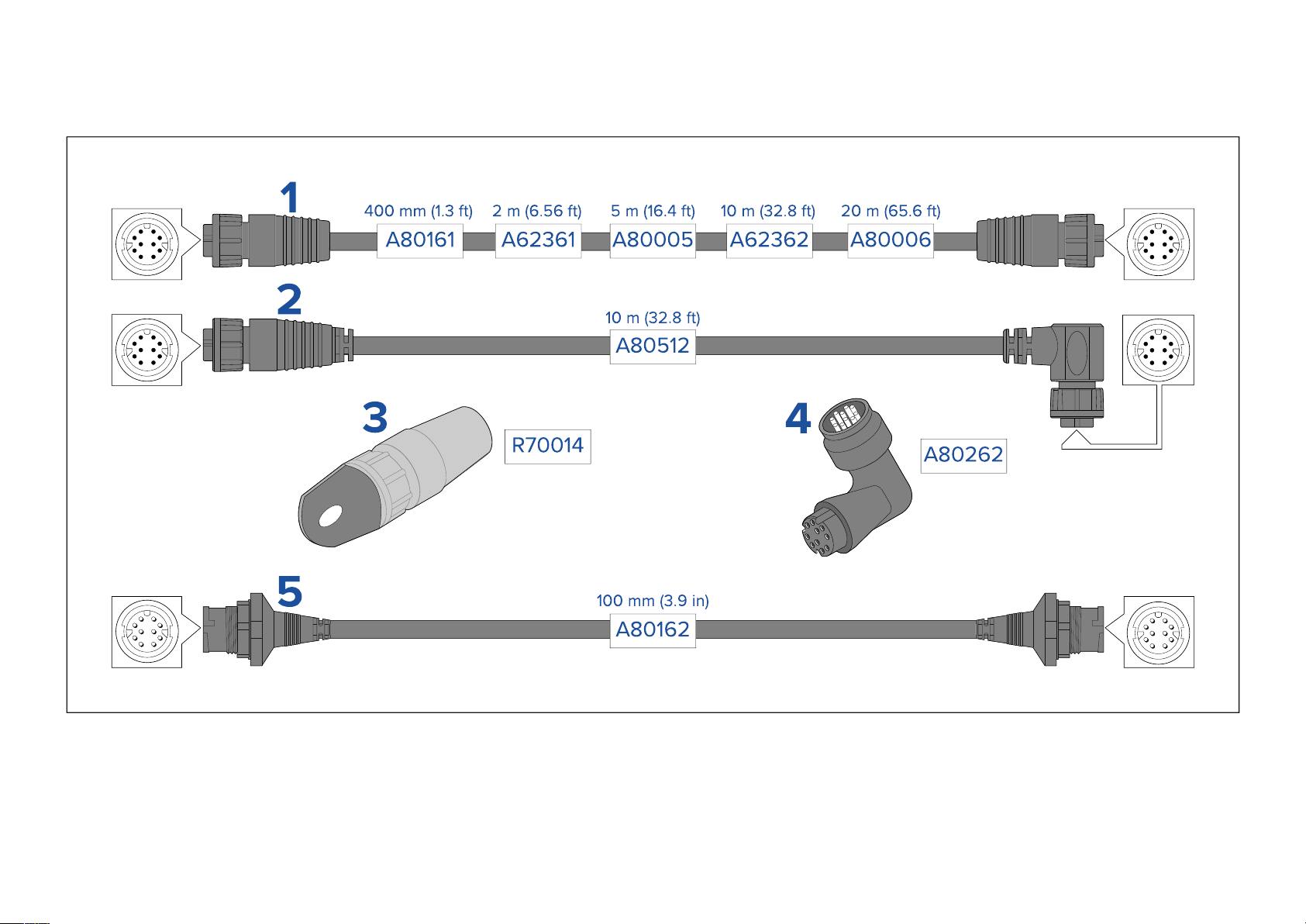
15.2Accessories
R
ayNettoRayNetcablesandconnectors
1.S tandardRayNetconnectioncablewithaRayNet(female)socketonbothends.
2.Right-angleRayNetconnectioncablewithastraightRayNet(female)socketononeend,andaright-angleRayNet(female)socketontheotherend.
Suitableforconnectingat90°(rightangle)toadevice,forinstallationswherespaceislimited.
3.RayNetcablepuller(5pack).
4.RayNettoRayNetright-anglecoupler/adapter.SuitableforconnectingRayNetcablesat90°(rightangle)todevices,forinstallationswherespaceislimited.
5.AdaptercablewithaRayNet(male)plugonbothends.Suitableforjoining(female)RayNetcablestogetherforlongercableruns.
Sparesandaccessories
49
Page 50
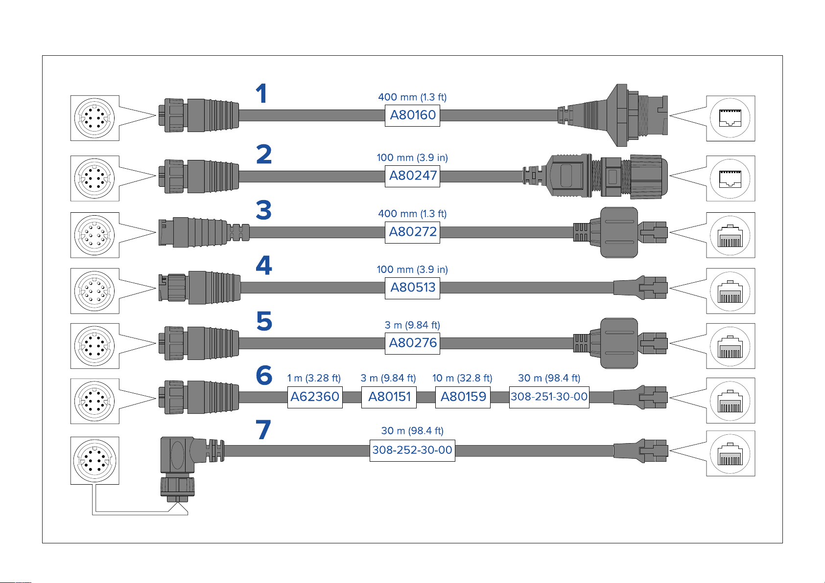
ayNettoRJ45,andRJ45(Sea Talkhs)adaptercables
R
50
Page 51

1.AdaptercablewithaR
ayNet(female)socketononeend,andawaterproof(female)RJ45(SeaTalkhs®)socketontheotherend,acceptingthefollowing
cableswithanRJ45(SeaT alkhs®)waterprooflocking(male)plug:
•A62245(1.5m).
•A62246(15m).
2.AdaptercablewithaRayNet(female)socketononeend,andawaterproof(female)RJ45(Sea Talkhs®)socketontheotherend,alongwithalocking
glandforawatertightfit.
3.AdaptercablewithaRayNet(male)plugononeend,andanRJ45(Sea Talkhs®)waterproof(male)plugontheotherend.
4.AdaptercablewithaRayNet(male)plugononeend,andanRJ45(male)plugontheotherend.
5.AdaptercablewithaRayNet(female)socketononeend,andanRJ45(SeaTalkhs®)waterproof(male)plugontheotherend.
6.AdaptercablewithaRayNet(female)socketononeend,andanRJ45(male)plugontheotherend.
7.Adaptercablewitharight-angledRayNet(female)socketononeend,andanRJ45(male)plugontheotherend.
Sparesandaccessories
51
Page 52

Page 53

Inde
x
Mountingtemplate.................................................................................11
A
Accessories.............................................................................................49
Networkadaptercables......................................................................50
Networkcables....................................................................................49
RayNetcables......................................................................................49
Applicableproducts..................................................................................11
C
Cable
Bendradius..........................................................................................25
Protection............................................................................................25
Routing................................................................................................25
Security................................................................................................25
Strainrelief...........................................................................................25
Cleaning...................................................................................................41
Compasssafedistance............................................................................21
Compatiblenetworkdevices....................................................................14
Connectingcables...................................................................................26
Connections................................................................................13,26–27
Battery.................................................................................................34
Distributionpanel.................................................................................34
Equipment............................................................................................30
Generalcablingguidance....................................................................25
Grounding............................................................................................36
Multipleswitches.................................................................................27
Overview..............................................................................................28
Power...................................................................................................33
Contactdetails.........................................................................................43
E
ElectromagneticCompatibility.............................................................7,20
EMC,SeeElectromagneticCompatibility
I
IgnitionProtection...................................................................................20
Installation
Bestpractice........................................................................................35
Mounting..............................................................................................22
Interference
Compass...............................................................................................21
L
Locationrequirements
General................................................................................................20
M
Maintenance.........................................................................................7,41
Mounting..........................................................................................22–23
N
Network
cables..................................................................................................50
Networkcableextension..........................................................................31
D
DeclarationofConformity..........................................................................8
Diagnostics..............................................................................................44
Exportingproductinformation.............................................................44
Viewingproductinformation...............................................................44
Dimensions...............................................................................................18
Documentation
Installationinstructions..........................................................................11
P
Partssupplied...........................................................................................16
Power
Batteryconnection...............................................................................34
Cableextension...................................................................................35
Connections.........................................................................................33
Distribution..........................................................................................33
Distributionpanel.................................................................................34
Grounding............................................................................................35
Page 54

Sharingabreak
Powercableextension............................................................................35
Productoverview......................................................................................13
Productrecycling(WEEE)..........................................................................8
Productsupport.......................................................................................43
er................................................................................34
R
RayNet
cables...........................................................................................49–50
Requiredadditionalcomponents.............................................................13
RJ45
cables..................................................................................................50
Routinechecks.........................................................................................41
S
SeaT alkhs
cables..................................................................................................50
ServiceCenter.........................................................................................43
Servicing...............................................................................................7,41
Spares.....................................................................................................48
Supportforum.........................................................................................44
Suppressionferrites............................................................................8,25
SeealsoEMC
Systemdiagram...........................................................................13,26–27
W
Warranty..............................................................................................8,43
WEEEDirective..........................................................................................8
T
Technicalspecification............................................................................45
Technicalsupport..............................................................................43–44
Toolsrequired.........................................................................................23
Trainingcourses......................................................................................44
Troubleshooting................................................................................38,44
NetworkLEDdiagnostics.....................................................................39
PowerLEDdiagnostics........................................................................38
Powerup..............................................................................................38
V
Ventilation...............................................................................................20
Page 55

Page 56

Raymarine (UK)
Marine House, Cartwright Drive,
Fareham, Hampshire.
PO15 5RJ.
United Kingdom.
Tel: (+44) (0)1329 246 700
www.raymarine.co.uk
Raymarine (US)
9 Townsend West,
Nashua, NH 03063.
United States of America.
Tel: (+1) 603-324-7900
www.raymarine.com
Raymarine Belgium BVBA (EU)
Luxemburgstraat 2, 2321 Meer.
Belgium.
Tel: (+32) (0) 3665 5162
www.raymarine.com
 Loading...