

Page 1

Distributed by
Any reference to Raytheon or
RTN in this manual should be
interpreted as Raymarine.
The names Raytheon and RTN
are owned by the
Raytheon Company.
Page 2

RayPilot 650 Control Unit
Owner’s Handbook
Document number: 81013-4
Date: July 2001
Page 3

ii RayPilot 650 Control Unit - Owner’s Handbook
Autohelm, HSB (High Speed Bus), SailPilot, SeaTalk and SportPilot
are registered trademarks of Raymarine Ltd.
Raymarine, AST (Advanced Steering T echnology), AutoAdapt,
AutoLearn, AutoRelease, AutoSeastate, AutoTack, AutoTrim,
FastTrim, GyroPl us, RayGyro, RayPilot and W indTrim are
trademarks of Raymarine Ltd.
Handbook contents © Raymarine Ltd 2001.
Page 4

Preface iii
Contents
Chapter 1: Introduction ............................................................1
1.1 Overview .................................................................................. 1
1.2 About this handbook .................................................................3
Important Information ..............................................................3
Chapter 2: Using the RayPilot 650 ...........................................7
2.1 Overview .................................................................................. 7
2.2 Auto mode .................................................................................8
Features .....................................................................................8
2.3 Navigation (Track) mode ..........................................................9
Features .....................................................................................9
2.4 Power steer ..............................................................................10
Features ...................................................................................10
2.5 Manual override (AutoRelease) - sterndrives only .................10
2.6 Display and keypad ................................................................. 11
Display ....................................................................................11
Keypad ....................................................................................11
Key functions ..........................................................................12
2.7 Response control .....................................................................18
Adjusting response – T ype 150G/400G ..................................18
Adjusting response – T ype s 150/400 and 100/300 ................. 19
2.8 Alarms and warnings ..............................................................20
Off Course alarm .....................................................................20
W aypoint Change alarm .............. ............................................20
Low Battery alarm ..................................................................21
No Drive alarm ........................................................................21
No Data alarm ......................................................................... 21
Data Invalid alarm ...................................................................22
Manual Override (AutoRelease) alarm ...................................22
Large XTE (Cross Track Error) alarm .................................... 22
2.9 Joystick operation ...................................................................23
Basic operation .......................................................................23
Proportional mode ..................................................................23
Bang-Bang mode ....................................................................25
Page 5

iv RayPilot 650 Control Unit - Owner’s Handbook
Chapter 3: Maintenance & Fault Finding ..............................27
3.1 Maintenance ........................................................................... 27
3.2 Servicing .................................................................................28
3.3 Product support ....................................................................... 28
Chapter 4: Installing the RayPilot 650 ..................................31
4.1 Planning the installation .........................................................31
4.2 Mounting the control unit .......................................................33
Location ..................................................................................33
Bracket mounting ................................................................... 34
Console mounting ...................................................................35
Cabling ....................................................................................36
4.3 Joystick installation (optional) ................................................37
Mounting ................................................................................ 37
Cabling ....................................................................................37
Chapter 5: Commissioning the Autopilot ............................39
5.1 Dockside checks ..................................................................... 39
Step 1 - Switch on ................................................................... 39
Step 2 - Check the SeaT alk and NMEA connections .............. 40
Step 3 - Check the autopilot operating sense ...........................40
Step 4 - Adjust basic autopilot settings ...................................43
5.2 Initial seatrial ..........................................................................46
Calibrating the compass .......................................................... 46
Adjusting autopilot settings .................................................... 49
Chapter 6: Adjusting Autopilot Settings ..............................55
6.1 T ype 150/150G and 400/400G course compu ters .................. 56
Accessing Calibration mode ................................................... 56
Calibration screens ................................................................. 56
Calibration defaults: T ypes 150/150G & 4 00/400G ............... 64
Calibration options: T ypes 150/150G & 400/400G ................65
6.2 Typ e 100/300 course computers ............................................. 66
Accessing Calibration mode ................................................... 66
Calibration screens ................................................................. 66
Dealer Calibration: default settings with T ype 100/300 ......... 73
Page 6
Chapter 1: Introduction 1
Chapter 1: Introduction
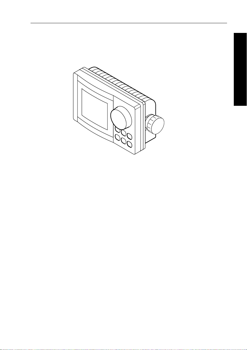
1.1 Overview
Congratulations on the purchase of your RayPilot 650 autopilot
control unit from Raymarine. W e have developed the RayPilot 650 to
integrate simplified controls with a sophisticated p rocessor to bring
you superb steering, no matter what the conditions. The t otally
waterproof control unit has features such as:
• an illuminated keypad, which takes the guesswork out of
• a rotary course knob which allows you to make accurate course
• a large easy to read display that provides you with graphic
1 Introduction
D5667-1
night-time use
changes by as little as 1°
representations of rudder angle, cross track error and much more
The RayPilot 650 has these basic operating modes:
• Stan dby mode: autopilot off
• Auto mode: autopilot engaged and locked onto a heading
• Navigator (T rack) mode: autopilot on and maintaining a track
between two waypoints created on a navigation system
• Wind V ane mode: autopilot on and maintaining a course relative
to an apparent wind angle
• Power Steer mode: allows full control of the boat via the cour se
change knob
• Calibration mode: so you can adjust the aut opilot system to give
optimum performance on your boat
Page 7

2 RayPilot 650 Control Unit - Owner’s Handbook
The RayPilot 650 is SeaTalk™ compatible, allowing it to share
information with other SeaT alk instruments. This becomes useful for
some automatic adjustments made by the autopilot. For example,
when the RayPilot is connected to a speed instrument, the speed gain
link allows the RayPilot to adjust the amount of rudder applied
according to the speed of the boat.
1 Introduction
When connected to a SeaT alk navigation aid or chart plotter via its
built-in interface, the RayPilot 650 will track to your waypoint with
amazing accuracy.
The RayPilot 650 system can be expanded and enhanced with a
selection of options and accessories available from your Raymarine
dealer. These include: further full function stations, a hand-held
control unit, a joystick power steering lever or an auxiliary alarm.
SeaTalk and NMEA compatibility
The RayPilot 650 control unit is SeaTalk compatible, so it can share
data transmitted from other Raymarine SeaT alk instruments :
• wind information from a wind instrument can be used for
wind vane steering without the need to install a separate vane
• track information, from a navigator, can provide waypoint control
from the autopilot
• boat speed from a speed instrument can provide optimum track
keeping performance
• SeaT alk compatibility also allows additional fixed and hand-held
autopilot control units to be easily connected at secondary
steering and control positions
If the RayPilot 650 is used as part of a course computer sys tem, you
can connect NMEA 0183 transmitting equipment to the ports on the
course computer. W ith an optional SeaT alk/NMEA interface (part
number: E85001), you can also connect NMEA 0183 equipment to
the SeaTalk ports on the RayPilot 650.
EMC conformance
All Raymarine equipment and accessories are designed to the best
industry standards for use in the recreational marine environment.
The design and manufacture of Raymarine equipment and
accessories conform to the appropriate Electromagnetic
Compatibility (EMC) standards, but correct installation is required to
ensure that performance is not compromised.
Page 8
Chapter 1: Introduction 3
1.2 About this handbook
Part 1: Using the RayPilot 650
This part of the handbook explains how to use yo ur RayPilot 650:
Chapter 2: Using the RayPilot 650
2
How to use the RayPilot 650
Chapter 3: Maintenance & Fault Finding
3
Provides maintenance and fault finding information.
page 7
page 27
Part 2: Installing the RayPilot 650
This part of the handbook explains how to inst all your RayPilot 650:
Chapter 4: Installing the RayPilot 650
4
How to install your RayPilot 650.
Chapter 5: Commissioning the Autopilot
5
How to check the autopilot and perform an initial sea trial.
Chapter 6: Adjusting Autopilot Settings
6
How to change the calibration settings.
Note: T his handbook contains important information about
installing, using and maintainin g your new Raymarine product. To
get the best from the product, please read this h andbook thoroughly.
page 31
page 39
page 55
1 Introduction
Important Information
Warranty
T o register your new Raymarine product, please take a few min utes to
fill out the warranty card. It is important that you complete the owner
information and return the card to us to receive full warranty benefits.
Handbook information
T o the best of our knowledge, the information in this handbook was
correct when it went to press. However, Raymarine cannot accept
liability for any inaccuracies or omissions it may contain. In addition,
our policy of continuous product improv ement may change
specifications without notice. As a result, Raymarine cannot accept
liability for any differences between the product and th e handbook.
Page 9

4 RayPilot 650 Control Unit - Owner’s Handbook
Safety notices
WARNING: Product installation
This equipment must be installed and operated in accordance
with the instructions contained in this handbook. Failure to do so
could result in poor pr oduct performance, personal injury
1 Introduction
and/or damage to your boat.
WARNING: Electrical safety
Make sure the power supply is switched off befor e you make any
electrical connections.
WARNING: Navigation aid
Although we have designed this pr oduct to be accurate and
reliable, many factors can affect its performance. As a result, it
should only be used as an aid to n avigation and should never
replace common s ense and navigational judgement. A lways
maintain a permanent watch so you can respond t o situations as
they develop.
Y our Raymarine autopilot will add a new dim ension to your boating
enjoyment. However, it is the skipper’s responsibility to ensure the
safety of the boat at all times by following these basic rules:
• Ensure that someone is present at the helm A T ALL TIMES, to
take manual control in an emergency .
• Make sure that all crew members know how to disengage the
autopilot.
• Regularly check for other boats and any obstacles to navigation –
no matter how clear the sea may appear, a dangerous situation can
develop rapidly .
• Maintain an accurate record of the boat’s po sition by using either
a navigation aid or visual bearings.
• Maintain a continuous plot of your boat’s position on a current
chart. Ensure that the locked autopilot heading will steer the boat
clear of all obstacles. Make proper allowance for tidal set – the
autopilot cannot.
• Even when your autopilot is locked onto the desired track using a
navigation aid, always maintain a log and make regular positional
plots. Navigation signals can produce significant errors under
some circumstances and the autopilot will not be able to detect
these errors.
Page 10

Part 1: Using the RayPilot 650
Part 1: Using the RayPilot 650
Page 11

Part 1: Using the RayPilot 650
Page 12

Chapter 2: Using the RayPilot 650 7
Chapter 2: Using the RayPilot 650
2.1 Overview
This section of the manual provides instructions for the operation of
your RayPilot 650.
The section starts by explaining the information available on the
control head display . A key by key guide follows, which doubles as a
useful reference lookup once you are familiar with the pilot’s
operation.
Y ou should read and und erstand this operation manual thoroughly
before operating the pilot. Time spent in becoming familiar with this
unit will strengthen your knowledge and skill in using this ful l feature
autopilot where it counts...afloat.
2 Using the RayPilot 650
Page 13
8 RayPilot 650 Control Unit - Owner’s Handbook
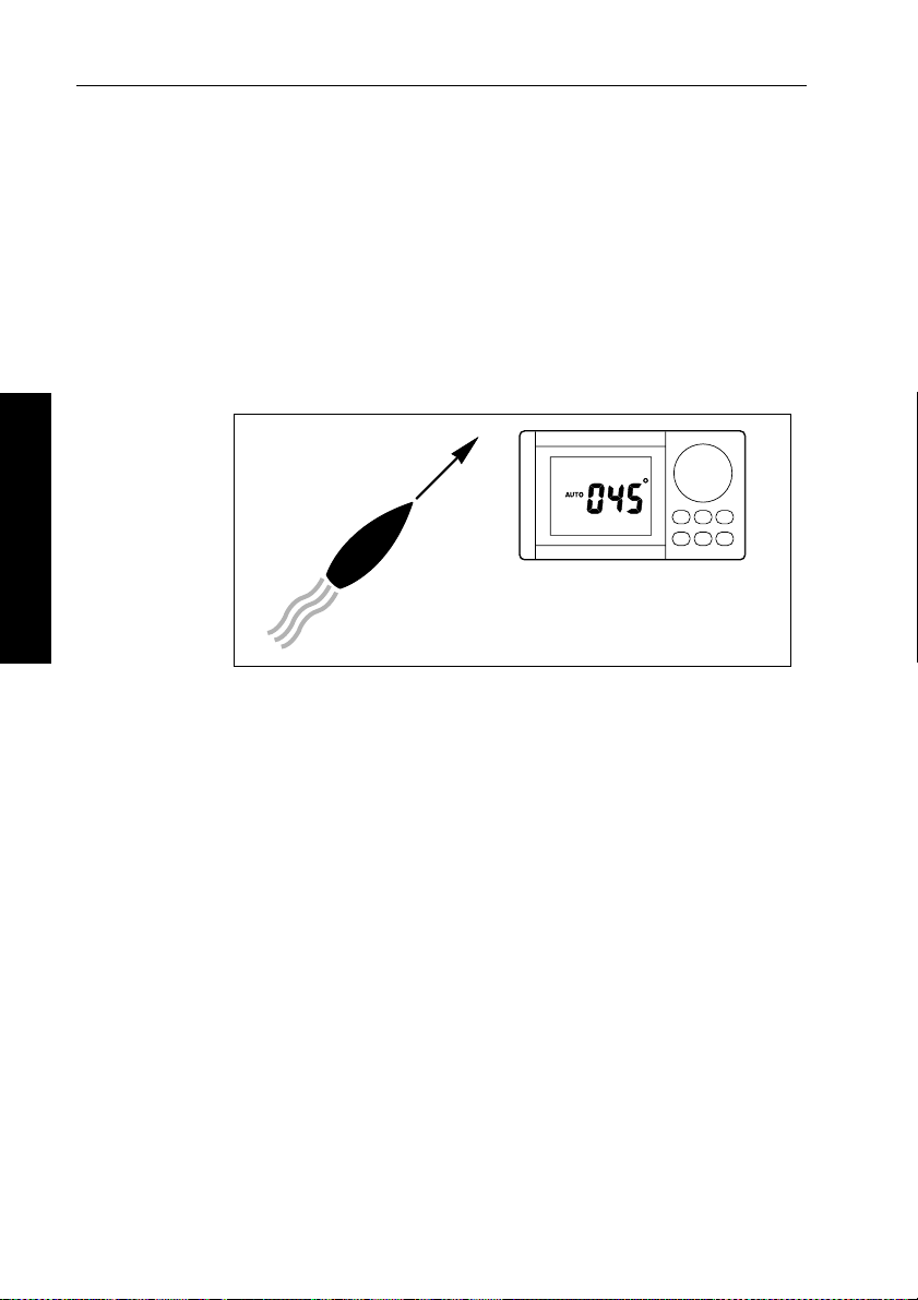
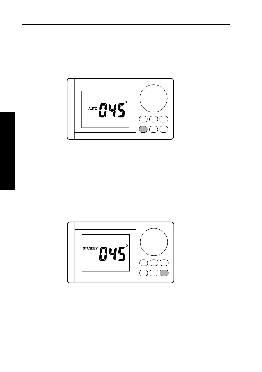
2.2 Auto mode
When the autopilot is in Auto mode it will maintain the boat on a
selected magnetic heading.
T o enter Auto mode, simply steer the boat onto the desired course and
then push
adjusting the knob so that the required new heading is displayed. The
RayPilot 650 will then automatically turn the boat onto the new
course. The maximum rate of turn is governed by a preset turn limit,
so even large course changes at speed are accomplished safely.
2 Using the RayPilot 650
Features
AUTO - it is that simple. Course changes can be made by
045˚
D850-1
In Auto mode, the RayPilot 650 displays the followin g information:
•
AUTO legend
• compass heading
• rudder angle
• boat speed (if available)
Page 14
Chapter 2: Using the RayPilot 650 9
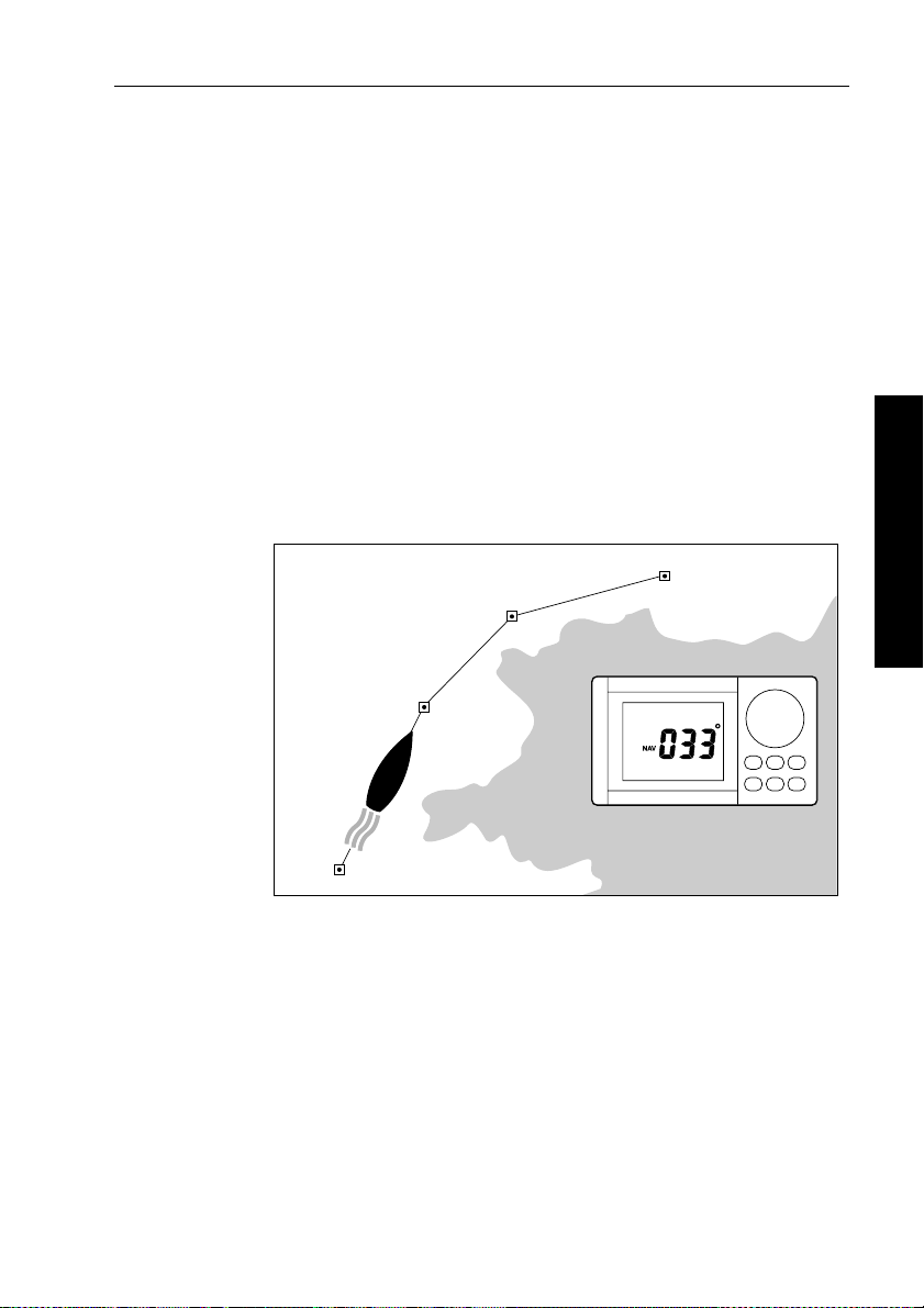
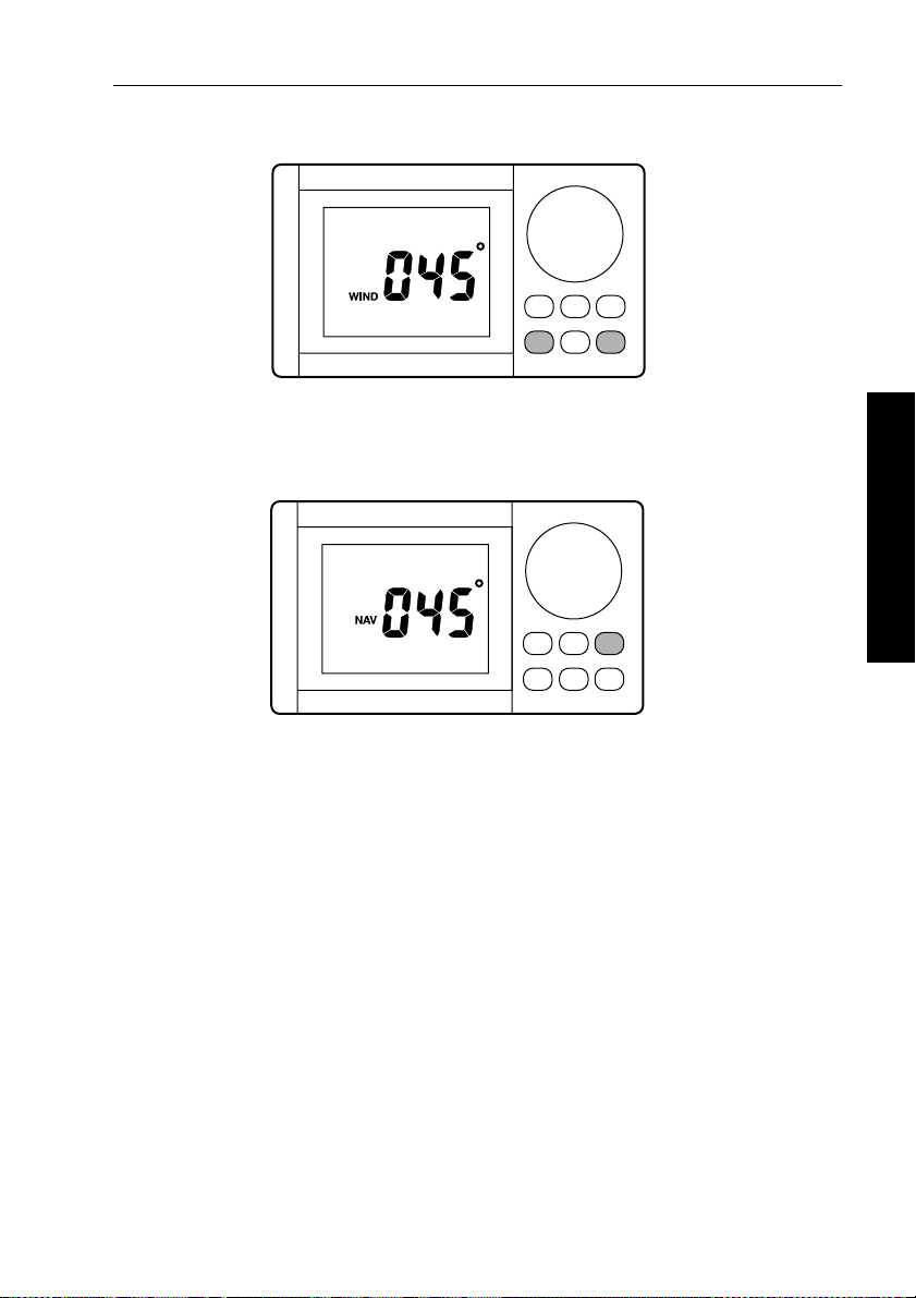
2.3 Navigation (Track) mode
Navigation mode relies on the input of your waypoint or r oute of
waypoints to provide tracking to destinati ons. Navigation mode is the
ultimate autopilot facility . Set up a waypoint or route of waypoints on
your navigation aid and the pilot will now monito r cross track error
and automatically execute course changes to maintain the boat’s
heading towards the target waypoint.
W e have developed this combination with safety utmost in mind.
When you reach your target waypoin t, the RayPilot 650 will sound an
alarm and display the bearing to the next waypoint along with the
direction in which the boat will turn. Y ou then check to see the turn
can be made safely. Now press the
for the next waypoint. This assures that no sudden course changes are
made without your knowledge.
002
001
NAV key to turn the boat on course
003
2 Using the RayPilot 650
D851-1
Features
In Navigation (T rack) mode, the RayPilot 650 displays the following
information:
•
• cross track error (XTE)
• target waypoint bearing, distance and number
• direction to steer
• boat speed (if available)
• locked compass heading
• rudder angle (selectable)
000
NAV legend
Page 15

10 RayPilot 650 Control Unit - Owner’s Handbook
2.4 Power steer
Power steer mode allows full control of the boat’s helm via the
course change knob. If you require helm to port simply rotate the
knob to port, helm to starboard turn the knob to st arboard. The
RayPilot 650 provides a continuous dis play of rudder position,
allowing you to position the helm accurately for steering in any
situation.
Features
In Power Steer mode, the RayPilot 650 di splays:
2 Using the RayPilot 650
•
POWER STEER legend
• compass heading and rudder angle
• boat speed (if available)
D853-1
2.5 Manual override (AutoRelease) - sterndrives only
Manual override is automatically enabled when vessel type 4
(sterndrive) is selected. It must only be used on in stallations fitted
with the stern drive actuator. When it has been selected, the RayPilot
can be overridden to allow hand steering by turning the steering
wheel. This will return the RayPilot to Standby mode and sound t he
control unit buzzer for 10 seconds.
There is a slight delay before the Raypilot will return to Standby .
Excessive force is not required and will not reduce this delay.
CAUTION:
The manual override is intended for emergency use only. The
RayPilot should normally be di sengaged by pressing
control unit.
STBY on the
Page 16
Chapter 2: Using the RayPilot 650 11
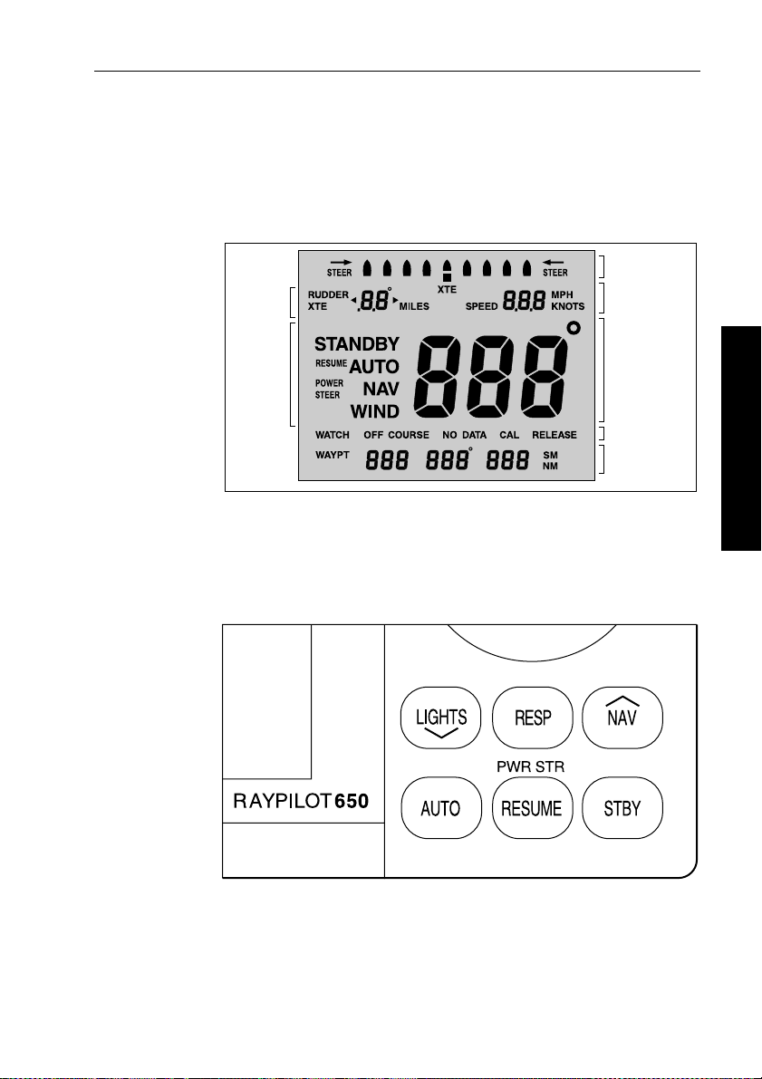
2.6 Display and keypad
Display
The RayPilot 650 display is designed to prov ide concise, clear
information. The display can be illuminated for night time operation.
Cross Track Error
or Rudder Angle
Selectable
Rudder/XTE
Boat Speed
Keypad
Autopilot
Mode
Heading
Alarms
Target Waypoint
Information
D854-1
The RayPilot 650 keypad is designed for quick and simple operation.
Each time a key is pressed a single audio beep confirms entry. The
6 keys have adjustable backlighting for night-time oper ation.
D856-1
2 Using the RayPilot 650
Page 17
12 RayPilot 650 Control Unit - Owner’s Handbook
Key functions
The following section describes the operation of each key and
provides a useful look-up reference.
AUTO
D857-1
• Momentary press to engage automatic steering and maintain
current heading.
• Momentary press in calibration will advance the display to the
next calibration feature.
2 Using the RayPilot 650
• Momentary press in Auto mode will reset the 4 minute watch
alarm timer (if running).
• Momentary press in compass correction mode will change
between compass correction and alignment.
STBY
D858-1
• Press to disengage the pilot for manual hand steering.
(The previous automatic heading will be memorized).
• Press and hold for 2 seconds to select rudder gain adjus tment.
• Press and hold for 4 seconds to select compass heading
alignment.
• Press and hold for 6 seconds to view software versi on.
• Press and hold for 16 seconds to access Calibration mo de.
Page 18
Chapter 2: Using the RayPilot 650 13
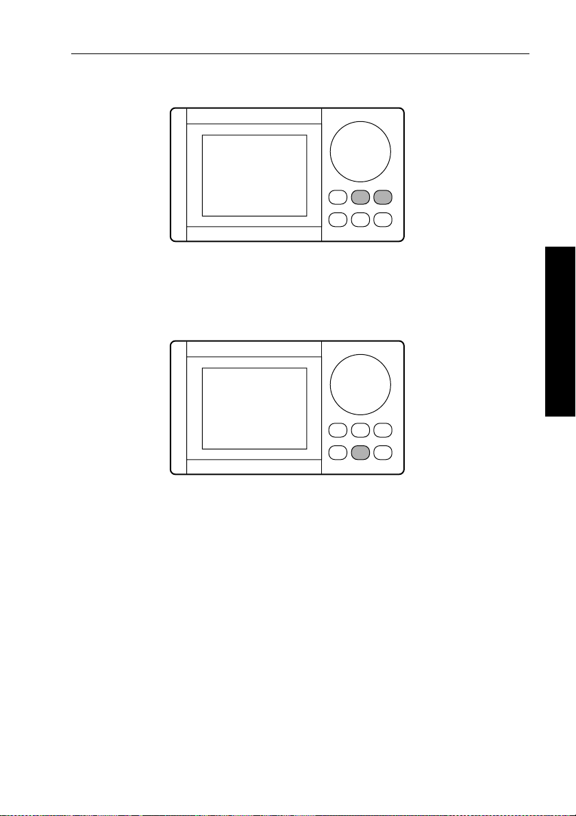
AUTO and STBY
D5661-1
• Press AUTO and STBY together from any other mode to enter
Wind Vane mode
NAV
D859-1
• Momentary press (while in Auto or W ind V ane Mode) flashes the
display between bearing to waypoint and direction the vessel will
turn.
• Second press within 10 seconds of the first press will engage
Navigation (Track) mode and turn the pilot onto the bearing to the
first waypoint.
• Press and hold for 2 seconds to automatically select the next
waypoint in a route (Raychart or SeaT alk compatible
plotter/GPS). This will also advance the T arget waypoint on the
Raychart if equipped.
2 Using the RayPilot 650
Page 19

14 RayPilot 650 Control Unit - Owner’s Handbook
RESP
D860-1
• Momentary press to display current rudder gain level.
• Press and hold for 2 seconds to display current response level.
• Y ou can then make temporary adjustments to the displayed
values using either:
LIGHTS ▼ to decrease the level
•
NAV ▲ to increase the level
•
• or the course change knob
2 Using the RayPilot 650
Note: Y ou can make permanent adjustments to response and rudder
gain in Calibration mode.
LIGHTS and RESP
D1007-1
• Momentary press of LIGHTS and RESP together will switch on
the W atch Alarm timer (not available from Standby or Power
Steer modes).
Page 20
Chapter 2: Using the RayPilot 650 15
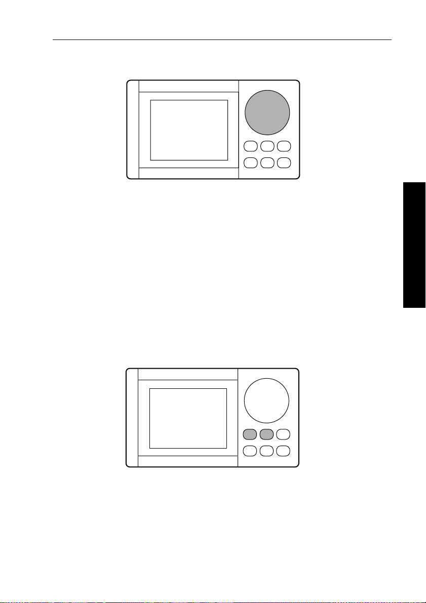
RESP and NAV
D1008-1D862-1
• Momentary press of RESP and NAV together will switch the
display between cross track error and rudder angle (displayed
value and scale).
RESUME (PWR STR)
• From Standby mode:
• press to display the last automatic heading – the heading will
alternate with the direction you have to steer
• press again within 10 seconds to lock onto th e last automatic
heading
• From Wind Vane mode:
• press to display the last locked wind ang le and direction
• press again within 10 seconds to return
• Press
RESUME for 2 seconds to engage Power Steer mode from
any mode (except calibration, compass correction and joystick
manual).
2 Using the RayPilot 650
Page 21
16 RayPilot 650 Control Unit - Owner’s Handbook
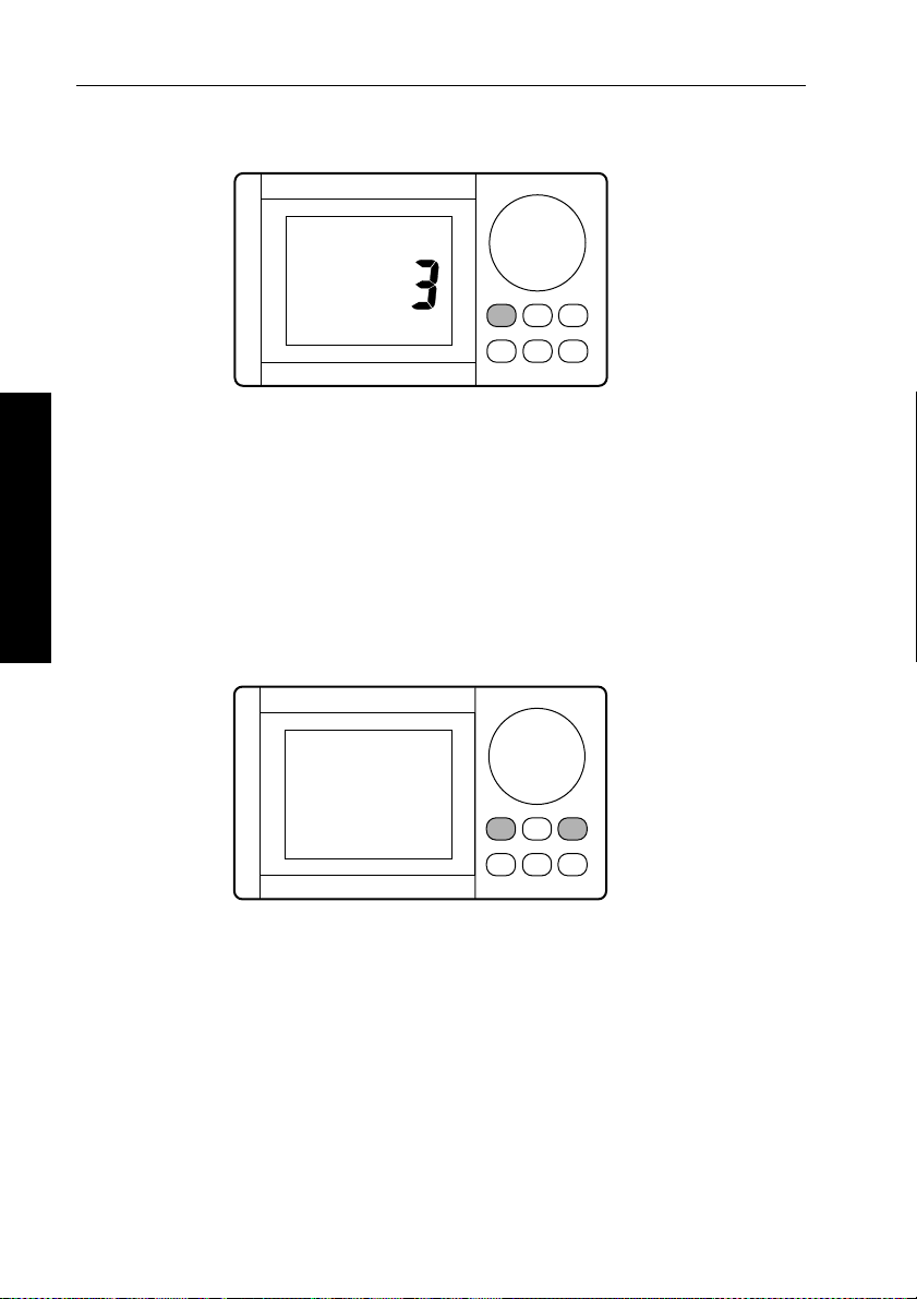
LIGHTS
D861-1
• Push LIGHTS to switch on and adjust the display and keypad
illumination:
•
0 = Off
1 = Minimum level
•
•
2 = Medium level
3 = Maximum level
•
• Press for 2 seconds to select displ ay contrast adjustment, of which
2 Using the RayPilot 650
there are 2 levels.
▲ (NAV) and ▼ (LIGHTS) keys
D862-1A
• Push to increase or decrease any adjustable function.
Page 22
Chapter 2: Using the RayPilot 650 17
Course change knob
D863-1
• Adjusts locked h eading
• Adjusts heading in Compass Correction mod e
• Moves rudder in Power Steer mode
• Adjusts values in Calibration mode
Watch alarm
The RayPilot 650 has a built in W atch Alarm. This is a timer t hat
flashes after 3 minutes and sounds an alarm on each control unit a
minute later. T o silence the alarm and reset the watch alarm to
4 minutes, press a key or rotate the course change knob.
Note: Watch alarm is not available in Stan dby or Power Steer modes.
T o enable/disable the watch alarm press
momentarily .
LIGHTS and RESP together
D1007-1
2 Using the RayPilot 650
Page 23

18 RayPilot 650 Control Unit - Owner’s Handbook
2.7 Response control
Adjusting response – Type 150G/400G
The main way you can adjust the performance of T ype 150G/400G
(GyroPlus) autopilot systems is by changing the response level. This
is the only user adjustment you should need to make to the autop ilot
on a regular basis.
The response level controls the relationship between the autopilot’s
course keeping accuracy and the amount of helm/drive activity .
T ype 150G and 400G autopilot systems have 9 levels of response:
• level 1 gives the least pilot activity to conserve power , but may
compromise short-term course-keeping accuracy
• levels 4 to 6 should give good course keeping u nder normal
operating conditions – with crisp, well cont rolled turns but
without being over-aggressive
• level 9 gives the tightest course keeping and greatest rudder
activity, bu t may lead to a rough passage in open waters as the
2 Using the RayPilot 650
autopilot may ‘fight’ the sea
When you require extra tight course keeping (e.g. for pilotage i n
confined and sheltered waters), increase the setting. If you want to
minimize drive activity and conserve battery power, decrease
the setting.
Y ou ca n adjust the default response level in Calibration mode. This
determines the default power-up response level. However , when
using your autopilot on a day-to-day basis, you can make temporary
adjustments to the response level. By doing thi s you can match
autopilot performance to different conditions.
Temporary changes to response – Type 150G/400G
With these points in mind, you should use the following procedure to
make temporary adjustments to the response level when required:
1. Display the
2. Use the
change the response level.
3. W ait for 5 seconds to return to the previo us display .
Note: Y ou will lose these temporary changes to response level
whenever the system is powered off. You can make permanent
adjustments in Calibration mo de.
RESPONSE screen by pressing RESP for 2 seconds.
▲ (NAV) or ▼ (LIGHTS) key or course change knob to
Page 24

Chapter 2: Using the RayPilot 650 19
Adjusting response – Types 150/400 and 100/300
T o adjust the performance of T ype 150/400 (without GyroPlus) and
T ype 100/300 autopilot systems you can change the response l evel.
Response level – Types 150/400 and 100/300
The response level controls the relationship between the autopilot’s
course keeping accuracy and the amount of helm/drive activity.
Y ou can adjust the default response level in Calibration mode. This
determines the default power-up response l evel.
However, when usi ng your autopilot on a day-to-day basis, you will
need to make temporary adjustments to the response level. By doing
this you can match autopilot performance to different conditi ons.
T ype 150/400 (without GyroPlus ) and T ype 100/300 autopilot
systems have three different response levels:
• Response Level 1: AutoSeastate on ( Automatic deadba nd)
This setting causes the autopilot to gradually ignore repetitive
boat movements and only react to true variations in course. This
provides the best compromise between power consumptio n and
course keeping accuracy, and is the default calibration setting.
• Response Level 2: AutoSeastate off (Minimum deadband)
This setting provides tighter course keeping. How ever, this
results in increased power consumption and drive unit activity .
• Response Level 3: AutoSeastate off + yaw damping
This setting provides the tightes t possible course keeping by
introducing counter rudder yaw damping. You can adjust the
counter rudder setting in Calibration mode.
To make a temporary change to the response setting:
1. Display the
seconds.
2. Use the
change the response between levels 1 to 3.
3. Wait for 5 seconds to return to the previous display.
RESPONSE screen by pressing the RESP keys for 2
▲ (NAV) or ▼ (LIGHTS) key or course change knob to
2 Using the RayPilot 650
Note: Y ou will lose these temporary changes to response level
whenever the system is powered off. You can make permanent
adjustments in Calibrat ion mode.
Page 25
20 RayPilot 650 Control Unit - Owner’s Handbook
2.8 Alarms and warnings
The RayPilot has a number of warning alarms that can be displayed.
An audible alarm will also sound at the same time.
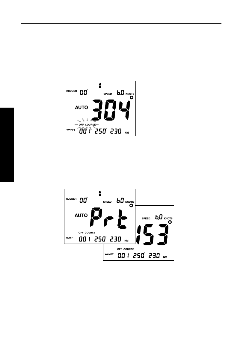
Off Course alarm
D987-1
The Off Course alarm sounds in Auto, Navigat ion (Track) and
Wind V ane modes when the current compass and the locked pilot
heading differ by more than the setting in calibration for a period of
2 Using the RayPilot 650
Waypoint Change alarm
20 seconds.
D988-1A
The W aypoint Change alarm sounds in Navigation (T rack) mode
when the target waypoint from the navigation aid changes.
The display alternates between the direction the boat will turn and the
bearing to the next waypoint in the route.
Page 26

Chapter 2: Using the RayPilot 650 21
Low Battery alarm
D989-1
The Low battery alarm sounds in all modes when the battery
voltage falls below 11.2 V (on 12 V installations) or 21 V (on 24 V
installations).
No Drive alarm
The No Drive alarm sounds in all modes if the drive unit is electrically
disconnected.
No Data alarm
2 Using the RayPilot 650
D990-1D991-1
The No Data alarm sounds in Navigation (T rack) mode when data has
not been received from a navigation aid.
Page 27

22 RayPilot 650 Control Unit - Owner’s Handbook
Data Invalid alarm
D992-1
The Data Invalid alarm sounds in Navigation (T rack) mode when
incorrect data has been received from a navigation aid.
Manual Override (AutoRelease) alarm
2 Using the RayPilot 650
D993-1D991-1
The Manual Override (AutoRelease) alarm sounds in all modes on
sterndrive installations when the helm is physically moved to regain
manual steering.
Large XTE (Cross Track Error) alarm
The Large XTE alarm sounds in Navigation (T rack) mode when
cross track error is greater than 0.3 nm.
Page 28

Chapter 2: Using the RayPilot 650 23
2.9 Joystick operation
The optional joystick (part number: M81 161) provides simple
power-assisted manual steer ing when the RayPilot 650 is used with
a T ype 100 or T ype 300 course computer .
Note: T his feature is not available on Type 150/150G or
Type 400/400G course computers
CAUTION:
Before use, familiarize yourself with joystick operation.
On power boats, always gain experience at low speeds before
using the joystick at higher speeds.
Basic operation
The autopilot system must be switched on at the main circuit breaker
before the joystick can be operated.
T o engage joystick control, press the control button (located in the
center of the lever) once. The RayPilot 650 will then display a
POWER STEER legend along with the current heading.
2 Using the RayPilot 650
The joystick can operate in either Proportional or Bang-Bang mode.
Y ou can select the required type is set up in Calibration mode.
Proportional mode
Proportional mode applies rudder in propor tion to joystick
movement. The further the joystick is held over the greater the
applied rudder (see illustrations on next page).
D996-1
Page 29

24 RayPilot 650 Control Unit - Owner’s Handbook
Proportional mode - applying port rudder
Small Helm Angle
Large Helm Angle
2 Using the RayPilot 650
Proportional mode - applying starboard rudder
Small Helm Angle
Large Helm Angle
D997-1
D998-1
Page 30

Chapter 2: Using the RayPilot 650 25
Bang-Bang mode
Bang-Bang (drive left – drive right) mod e applies continuous rudder
drive in the direction of joystick movement. T o improve control, the
speed of rudder movement changes with the angle of the lever: for
maximum speed push the lever hardover. If the lever is returned to the
center position the rudder will remain in its current position.
The spring action should not be removed for Bang-Bang operation.
Bang-Bang mode - applying port rudder
D999-1
Bang-Bang mode - applying starboard rudder
2 Using the RayPilot 650
D1000-1
Page 31

26 RayPilot 650 Control Unit - Owner’s Handbook
2 Using the RayPilot 650
Page 32

Chapter 3: Maintenance & Fault Finding 27
Chapter 3: Maintenance & Fault Finding
This chapter provides information about maintaini ng your RayPilot
and obtaining product support.
3.1 Maintenance
CAUTION:
The RayPilot control unit does NOT contain any user serviceable
parts. It should be repaired only by authorized Raymarine
service representatives.
Maintaining satisfactory operation of your Ray Pilot and system
components will depend on how well you care for the equipment.
The basic maintenance tips that follow can save you time and mo ney,
as well as prevent unnecessary and premature failures.
• Always keep the equipment as clean as possible.
• Use a soft clean cloth for cleaning instrumentation. Do not use
abrasive cleansers, chemical cleaners or solvents. Use glass
cleaners or a suitable general purpose detergent.
• Periodically examine the system hardware.
• Examine all cables for possible chafing or abrasions; clean and
repair as necessary.
• Make sure connections to the boat’s power supply and RF ground
system are clean and tight – a light film of a high insulation
silicone grease (eg, Dow Corning DC-4) on connector pins can
protect the plug contacts from corrosion.
3 Maintenance & Fault Finding
EMC advice
• When powered up, all electrical equipment produces
electromagnetic fields. These can cause adjacent pieces of
electrical equipment to interact with one another, with a
consequent adverse effect on operation.
• T o minimize these effects and enable you to get the best possible
performance from your Raymarine equipment, guidelines are
given in the installation instructions, to enable you to ensure
minimum interaction between different items of equipment,
i.e. ensure optimum Electromagnetic Compatibility (EMC).
Page 33

28 RayPilot 650 Control Unit - Owner’s Handbook
• Always report any EMC-related problems to your n earest
Raymarine dealer. We use such information to improve our
quality standards.
• In some installations, it may not be possible to preven t the
equipment from being affected by ext ernal influences. In general
this will not damage the equipment but it can lead to spurious
resetting action, or momentarily may result in faulty operation.
3.2 Servicing
WARNING:
The RayPilot 650 control unit has an electro-fluorescent panel to
provide disp lay backlighti ng. The circui try used to driv e this
panel generates approximately 300 V. Y ou must NOT operate the
unit is with its cover removed.
Servicing should only be carried out by qualified s ervice agents or
authorized service centers.
3.3 Product support
All Raymarine products are designed to provide many years of
trouble-free operation. W e also put them through comprehensive
testing and quality assurance procedures befo re shipping.
Raymarine products are supported by a worldwide network of
distributors and Authorized Service Representa tives.
Before you consider returning the autopilot, make sure that the power
supply cable is sound and that all connections are tight and free fr om
corrosion. If you cannot trace or rectify the fault, contact either your
3 Maintenance & Fault Finding
national distributor, serv ice representative, or the Raymarine
T echnical Services Call Center. Refer to the back cover or the
W orldwide Distributor List for contact details.
Always quote the product serial number, which is printed on the back
of the control unit.
Page 34

Part 2: Installing the RayPilot 650
Part 2: Installing the RayPilot 650
Page 35

Part 2: Installing the RayPilot 650
Page 36

Chapter 4: Installing the RayPilot 650 31
Chapter 4: Installing the RayPilot 650
4.1 Planning the installation
Before you start installing your RayPilot 65 0, read through the
following information to help you determine where to locate the
RayPilot and route its cables.
Cabling guidelines
• consider how you will run cables to and from each component
• avoid running cables through bilges wh ere possible
• avoid running cables close to fluorescent lights , engines, radio
transmitting equipment etc.
EMC installation guidelines
All Raymarine equipment and accessories are designed to the best
industry standards for use in the recreational marine environment.
Their design and manufacture conforms to the appropriate
Electromagnetic Compatibility (EMC) standards, but correct
installation is required to ensure that performance is not compromised.
Although every effort has been taken to ensure that they will perform
under all conditions, it is important to underst and what factors could
affect the operation of the product.
The guidelines given here describe the conditions for op timum EMC
performance, but it is recognized that it may not be possible to meet
all of these conditions in all situations.
T o ensure the best possible conditions for EMC performance wit hin
the constraints imposed by any location, always ensure the maximum
separation possible between different items of electrical equipment.
For optimum EMC perfo rmance, we recommend that:
• Raymarine equipment and cables connected to it are:
• At least 3 ft (1 m) from any equipment transmitting o r cables
carrying radio signals e.g. VHF radios, cables and antennas.
In the case of SSB radios, increase the distance to 7 ft (2 m).
• More than 7 ft (2 m) from the path of a radar beam. A radar
beam can normally be assumed to spread 20 degrees above
and below the radiating element.
4 Installing the RayPilot 650
Page 37

32 RayPilot 650 Control Unit - Owner’s Handbook
• The equipment is supplied from a separate battery from that used
for engine start. Voltage drops below 10 V, and starter motor
transients, can cause the equipment to reset. This will not damage
the equipment, but may cause the loss of some information and
may change the operating mode.
• Raymarine specified cables are used. Cutting and rejoining these
cables can compromise EMC performance and must be avoided
unless doing so is detailed in the installation manu al.
• If a suppression ferrite is attached to a cable, this ferrite shoul d not
be removed. If the ferrite needs to be removed d uring installation
it must be reassembled in the same position.
EMC suppression ferrites
W e supply the fluxgate compass and p ower cables with suppression
ferrites fitted. Always use these ferrites supplied by Raymarine.
4 Installing the RayPilot 650
D3548-2
Connections to other equipment
If your Raymarine equipment is to be connected to other equipment
using a cable not supplied by Raymarine, a suppression ferrite MUST
always be attached to the cable near to the Raymarine unit.
Page 38

Chapter 4: Installing the RayPilot 650 33
4.2 Mounting the control unit
233 mm (9.2 in) 74 mm (2.9 in)
193 mm (7.6 in)
33 mm
(1.3 in)
110 mm (4.3 in)
123 mm (4.8 in)
The RayPilot control unit is fully weather protected and i s designed
for above or below deck installation. Connection to the cours e
computer is made via the SeaT alk bus.
RayPilot control units can be mounted on a chart tabletop, suspended
overhead or attached to a bulkhead using the bracket supplied.
Location
Mount the RayPilot control unit close to the steering station where it
will be:
• normally viewed straight on for best display legibil ity
• well protected from physical damage
• at least 230 mm (9 in) from a compass
• at least 500 mm (20 in) from radio receiving equipment
• accessible from behind to install and run cables
47.5 mm (1.87 in)
D866-1
4 Installing the RayPilot 650
Page 39
34 RayPilot 650 Control Unit - Owner’s Handbook
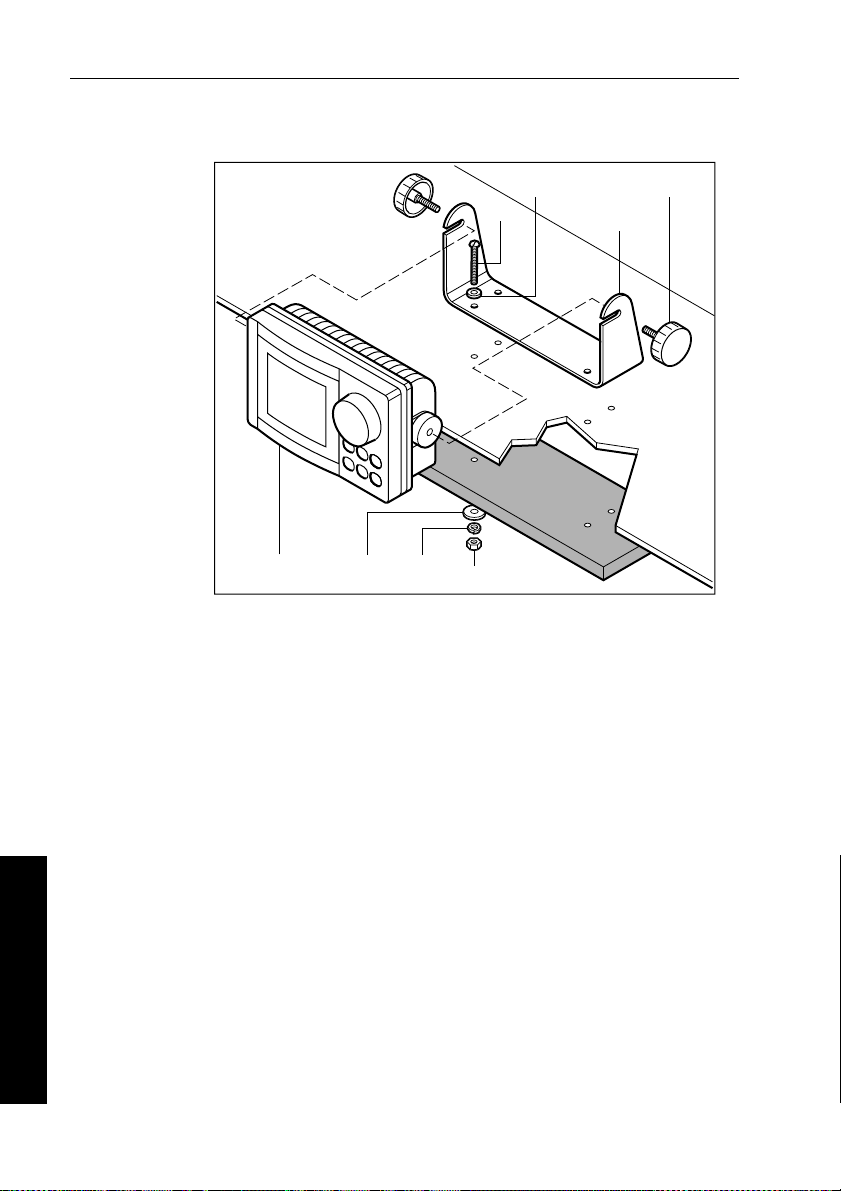
Bracket mounting
Control
unit
Seating
washer
Lock
washer
Washer
Screw
Nut
Knob
Mounting
bracket
D883-1
1. Remove the mounting bracket from the RayPilot control unit by
loosening the knob on each side.
2. Attach the bracket to the selected location with the screws,
washers, seating washers, lock washers and nut.
3. Slide the RayPilot control unit into the bracket and secure in
position by tightening the knobs.
4 Installing the RayPilot 650
Page 40
Chapter 4: Installing the RayPilot 650 35
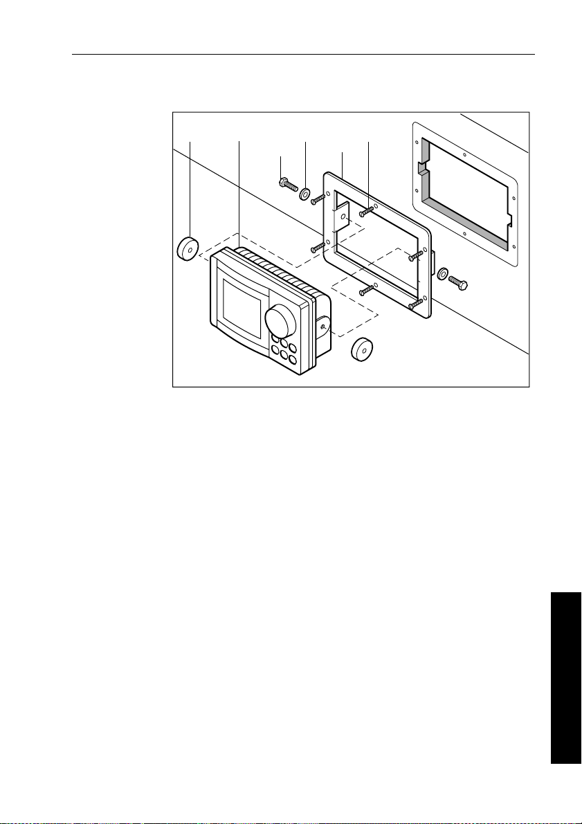
Console mounting
Rubber
spacer
1. Select a clear location at least 228 mm x 127 mm (9 in x 5 in) by
2. Attach the supplied template to the console and drill a pilot hole
3. Use a suit able saw to cut a hole to match the template.
4. Fit the bracket and secure using the six screws.
5. Assemble the RayPilot control unit to the bracket and secure
Control
unit
Bolt
(x2)
Washer
(x2)
127 mm (5 in) deep.
inside the rectangular hole.
using the bolts and washers.
Bracket
Screw
(x6)
D885-1
4 Installing the RayPilot 650
Page 41
36 RayPilot 650 Control Unit - Owner’s Handbook
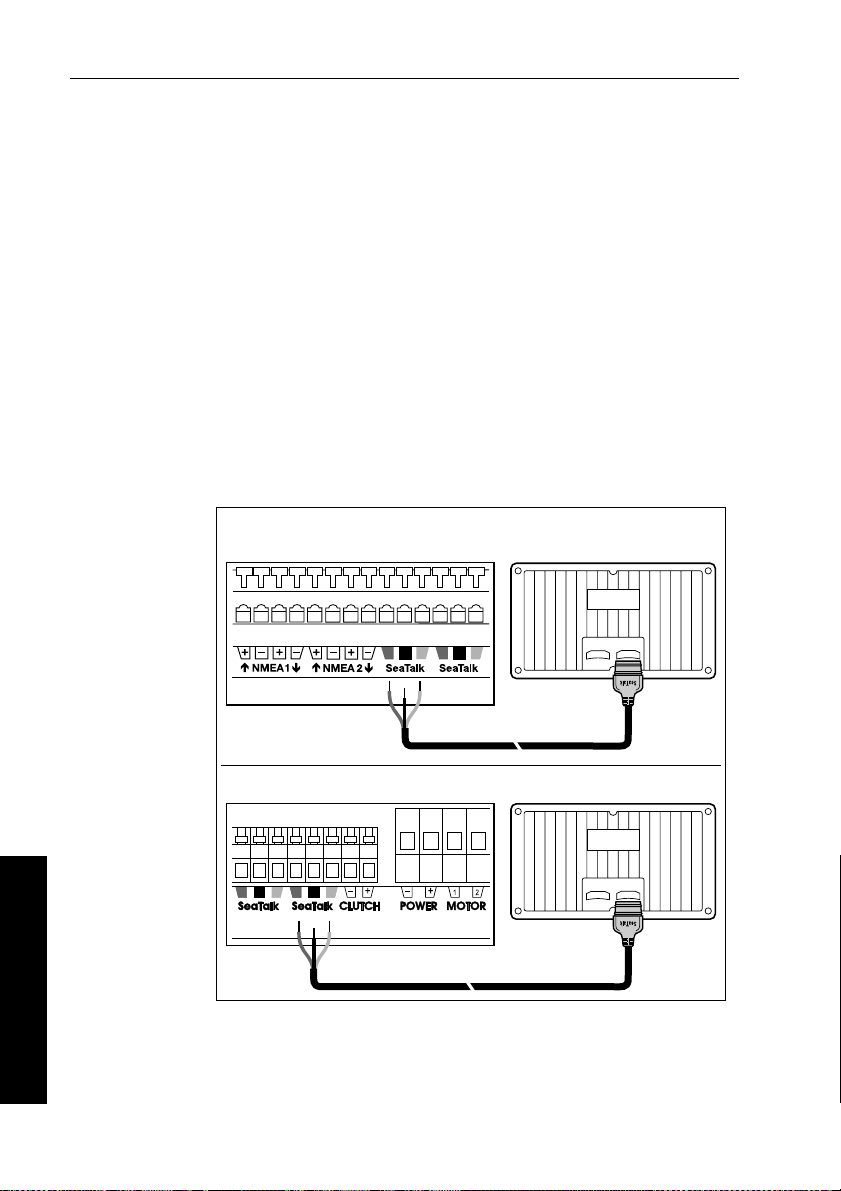
Cabling
The RayPilot control unit is provided with a 9 m (30 ft) SeaT alk cable
fitted with a flat moulded 3-pin socket on each end. The SeaTalk
cable provides power to the control unit and allows it to share data.
1. Plug one end of the cable into one of the two SeaT alk sockets on
the back of the RayPilot control unit.
2. Run the SeaTalk cable back to the course computer , bearing in
mind the EMC and cabling guidelines at the start of this chapter.
Note: If the control unit is not the main autopilot control unit, run the
SeaTalk cable to the main control unit and connect to the free SeaTalk
socket on the rear of the unit.
3. Cut the remaining plug from the SeaTalk cable and connect to the
wires to the SeaTalk terminals on the course computer as shown
in the following illustration.
Connecting to course computer as main control unit
Type 150/400 course computer terminals
4 Installing the RayPilot 650
Red
Screen
Type 100/300 course computer terminals
Red
Screen
Yellow
Yellow
D886-2
Note: If your boat is already fitted with ST50 instruments, connect the
RayPilot to the SeaTalk system using an interface cable wit h a round
plug. The course computer can sup ply power for the complete system.
Page 42

Chapter 4: Installing the RayPilot 650 37
4.3 Joystick installation (optional)
Note: T he joystick is an option for Type 100/300 course com puters.
Mounting
The mounting surface must be smooth and flat to insure t hat there is
adequate waterproofing.
1. Use the template provided to mark the centers for the two fixing
holes and outline of the body aperture.
2. Drill the fixing holes and cut-out the aperture for the body.
3. Remove the mounting template.
4. Peel off the protective paper from the rear of the weather gasket
and fix to the mounting surface.
5. Pass the cable through the body aperture and secure the joystick
with the thumb nuts provided.
Cabling
The joystick is supplied with 26ft (8m) of cabl e which should be
connected to the T ype 100/300 course computer as shown.
Red
Screen
Green
Blue
D984-1
Note: Only one joystick can be connected to the course computer.
R1004-1
4 Installing the RayPilot 650
Page 43

38 RayPilot 650 Control Unit - Owner’s Handbook
4 Installing the RayPilot 650
Page 44

Chapter 5: Commissioning the Autopilot 39
Chapter 5: Commissioning the Autopilot
WARNING:
All new autopilot system installations MUST be calibrated.
If you have connected the RayPilot 650 to a newly installed
course computer autopilot system, you must commission the system
This involves a series of dockside checks and then the seatrial
calibration:
Note: Before completing the procedures in this section, complete the
‘Post installation checks’ described in the drive installation guide.
5.1 Dockside checks
With the boat safely tied up, complete the following dockside checks:
1. Switch on.
2. Check the SeaTalk and NMEA connections.
3. Check the autopilot operating sense.
4. Set the basic autopilot parameters.
WARNING:
For safe con trol of your bo at, you MUST co mplete the dock side
checks before starting the initial seatrial.
5 Commissioning the Autopilot
Step 1 - Switch on
1. When you have installed the RayPilot control unit and the rest of
the autopilot system, switch on the main power breaker.
2. If the control unit and system are active, the control unit will beep
and then display the
3. Check that the
.
STANDBY screen.
STANDBY screen displays a live compass heading.
D858-1
Page 45

40 RayPilot 650 Control Unit - Owner’s Handbook
Step 2 - Check the SeaTalk and NMEA connections
SeaTalk connections
If you have connected the RayPilot to other SeaT alk instruments or
control units, check the links as follows:
1. Select display lighting level 3 (
instruments or control units.
2. The RayPilot should immediately switch on its d isplay lighting:
5 Commissioning the Autopilot
• if the lighting does not switch on, there is a fault in the SeaTalk
cabling between the RayPilot and the other units
NMEA navigator connections
If you have connected the autopilot system to an NMEA navigator ,
check the links by setting an active waypoint on the navigator . After a
brief delay , the RayPilot should show the waypoint information at the
bottom of its screen.
Wind instrument connections
If you have connected the autopilot to an NMEA or SeaT alk wind
instrument, check the links by pressing
• the RayPilot should display the W ind V ane mode screen, with the
locked wind angle and locked heading:
• if nothing happens when you press
RayPilot is not receiving wind data: check the wind instrument
and connections
LAMP 3) on one of the SeaT alk
AUTO and STBY together:
AUTO and STBY together , the
Step 3 - Check the autopilot operating sense
Check the rudder position sensor
1. Turn the wheel manually to starboard.
2. Check that the rudder bar on the display moves to starboard.
If the rudder bar display moves to port:
• turn off the power
• reverse the red and green wires connected to the
inputs on the course computer
• switch on the power and re-check
RUDDER
Page 46

Chapter 5: Commissioning the Autopilot 41
Check the autopilot steering sense
1. Manually center the wheel, then press the AUTO key so the
autopilot is in Auto mode. Check that the display show s
Be ready to pr ess
standby if the rudder moves hardover.
2. Turn the course change knob clockwise. Check that the rudder
moves to starboard a few degrees and then stops.
• if the rudder drives hardover , immediately press
prevent further rudder movement
If the rudder moves to port or the rudder drives hardover:
• press
STBY
• turn off the power
• reverse the motor wires connected to the course computer
• switch on the power and re-check
Note: If the rudder overshoots and has to drive back or starts to hunt
back and forth, you will need to increase the rudder damping level as
described in Step 5 (see page 45).
AUTO.
STBY to
D853-1
5 Commissioning the Autopilot
Mechanical system tests
Mechanical test (linear, rotary and hydraulic drives)
WARNING:
When the steering system is being moved manually, or under
drive from the autopilot, do not to uch any part of the system. The
forces exerted are considerable and could cause injury.
1. Push
2. Turn the course change knob to drive the rudder hardover onto the
3. Make sure the drive unit mounting shows no sign of movement.
AUTO.
end stops (Note: This may require increasing the rudder limit in
the calibration mode).
Page 47

42 RayPilot 650 Control Unit - Owner’s Handbook
4. For hydraulic systems, make sure there is no seepage of hydraulic
fluid and that the steering ram moves smoothly .
CAUTION:
If the installation is a non Raymarine Constant Running Pump,
firstly check that the system includes a pressure relief valve.
Failure to do this could cause damage to the steering system.
5. Repeat driving the rudder hardover to the opposite end stop.
5 Commissioning the Autopilot
Current limit and cut-out
When the rudder is driven onto the end stops the power to t he drive
will be cut out after a few seconds - this is normal. Drive will only be
restored if the rudder moves away from the end stop or if drive is
required in the opposite direction.
Mechanical test (sterndrives)
It is recommended that the Auto Release facility is used when a
Raymarine mechanical sterndrive unit is installed. This is
automatically selected when the vessel type in calibration is set to 4.
1. Manually drive the steering hard-over to starboard.
2. With the boat’s engines running, engage power steer and drive the
steering to the opposite lock (Port) using the course chang e knob.
3. The autopilot should drive the steering onto the end s tops, sound
an alarm while displaying the
Standby mode.
4. Re-engage power steer and repeat driving the steering hard to
starboard using the course change knob.
5. The autopilot should again drive onto the end stop, alarm/display
RELEASE and return to standby .
Note: If the unit sounds the alarm and displays
reaching the opposite lock, carefully check the boat’s steering system
for any stiffness or mechanical jamming.
RELEASE message and then revert to
RELEASE before
If the condition persists, set the Auto Release function to “off” (0) in
calibration and contact the Technical Services Department at
Raymarine for further advice.
Note: T he Auto Release function should always be set to “off” (0) in
calibration if using any driv e unit other than a sterndrive unit.
Page 48

Chapter 5: Commissioning the Autopilot 43
Step 4 - Adjust basic autopilot settings
The next step in the dockside set-up is to enter Calibration mode so
you can adjust some basic autopilot settings.
Enter Calibration mode
1. Start with the autopilot in St andby mode.
2. Enter Calibration mode as follows:
• press and hold
shows
• press STBY and AUTO together to enter Calibration mode
• the first screen you should see
Set the vessel type
1. The first screen you should see when y ou enter Calibration mode
is the V essel T ype screen
Note: If necessary, use the
screens until you reach the Vessel Type screen.
2. Use the
▲ (NAV) or ▼ (LIGHTS) key or course change knob to
select a vessel type suitable for your boat:
Options
1 Displacement powerboat
2 Semi-displacement powerboat
3 Planing powerboat
4 Planing powerboat with I/O drive (stern drive)
5 Work boat (150/150G and 400/400G only)
6 Sail boat (150/150G and 400/400G only)
STBY for 16 seconds until the display
CAL
(vES tYP).
AUTO key to page through the Calibration
5 Commissioning the Autopilot
Note: When you s elect the vessel type, the autopilot will select
appropriate defaults for various other calibration settings.
Page 49

44 RayPilot 650 Control Unit - Owner’s Handbook
Set the drive type
1. With the autopilot still in Dealer Calibration, use the AUTO key to
page through the calibration screens until you reach the Drive
T ype screen (
2. Use the
drv oPt).
▲ (NAV) or ▼ (LIGHTS) key or course change knob to
make sure the appropriate drive type is selected for your boat:
Options
3 Linear drive, rotary drive or I/O (stern) drive
5 Commissioning the Autopilot
4 Hydraulic pump or hydraulic linear drive
5 Constant running hydraulic pump solenoids
Align the rudder position sensor
1. With the autopilot still in Calibration mode, press the AUTO key
to page through the calibration screens until you reach the
Align Rudder screen (
rUd Add).
2. Use the wheel to manually center the rudder.
3. Use the
▲ (NAV) and ▼ (LIGHTS) keys or course change knob
to adjust the displayed rudder bar so its of fset is zero:
• you can only use this screen to adjust offsets within ±7°: if the
offset is beyond these limits, you will need to ph ysically
adjust the sensor’s alignment (as described in the Autopilot
System Installa tion Guide)
Note: Al ternatively, you can zero the rudder bar with the boat
underway during the initial seatri al, by manually steering a straight
course then accessing the Align Rudder screen to adjust the offset.
Set the rudder limits
1. With the autopilot still in Calibration mode, press the AUTO key
to page through the Calibration screens until you reach the
Rudder Limit screen (
rUd StP).
2. Turn the wheel to move the rudder:
• to the port end stop and note the angle
• to the starboard end stop and note the angle
3. Use the
▲ (NAV) or ▼ (LIGHTS) key or course change knob to
set the rudder limit to 5° less than the lowest angle you have
noted.
Page 50

Chapter 5: Commissioning the Autopilot 45
Adjust the rudder damping
Note: Y ou only need to adjust the rudder damping value if the
autopilot ‘hunts’ when trying to position the rudder. Increasing the
rudder damping value reduces hunting.
T o adjust the rudder damping:
1. Use the
you reach the Rudder Damping screen (
2. Use the
adjust the rudder damping:
• increase the damping one level at a time until the autopilot
AUTO key to page through the Calibration screens until
rUd dPG).
▲ (NAV) or ▼ (LIGHTS) key or course change knob to
stops hunting, and always use the lowest acceptable value
Save the new settings
When you have adjusted these basic settings in Dealer Calibration:
• press and hold
• the screen will then show the
STBY for two seconds to store the changes
STANDBY screen
5 Commissioning the Autopilot
Page 51

46 RayPilot 650 Control Unit - Owner’s Handbook
5.2 Initial seatrial
After competing the dockside calibration, you must complete t he
setup by taking the boat on a short seatrial to:
1. Calibrate the compass:
• complete the automatic deviation correction
• align the compass heading
2. Adjust the autopilot settings to suit your boat.
5 Commissioning the Autopilot
Seatrial safety
Note: You can return to hand steering at any time during the
seatrial by pressing
Y ou should only perform the initial seatrial:
• when you have successfully completed the dockside calibration
• in conditions of light wind and calm wat er, so you can assess
autopilot performance without the influence of strong wi nds or
large waves
• in waters that are clear of any obstructions, so the boat has plenty
of clear space to maneuver
Note: Before you start your seatrial, make s ure you have switched on
any ancillary equipment – such as a GPS (provi ding course over
ground (COG), speed over groun d (SOG) and latitude (LAT) data) or
a speed log (providing speed through the water). T his information
will help the autopilot achieve its best performance.
stby.
CAUTION: EMC conformance
Always check the installation before going to sea to make sur e
that it is not affected by radio transmissions, engine starting etc.
Calibrating the compass
Note: T his section does not apply if you have connected an NMEA
compass to your autopilot system. Refer to t he handbook supplied
with the NMEA compass for information a bout calibration.
Depending on your boat type, deviating magnetic fields can cause
significant compass errors. The correction procedure reduces these
errors to a few degrees, so you MUST perform this procedure as the
Page 52
Chapter 5: Commissioning the Autopilot 47
first item in your initial seatrial. The autopilot will then automatically
correct the fluxgate compass.
CAUTION:
If you fail to complete the deviation correction, your autopilot’s
performance will be impaired on some compass headings.
The deviation correction procedure (swinging the compass) involves
turning your boat in slow circles so the autopilot can determine the
deviation and calculate any correction required. You must carry out
this procedure in calm conditions and preferably on flat water .
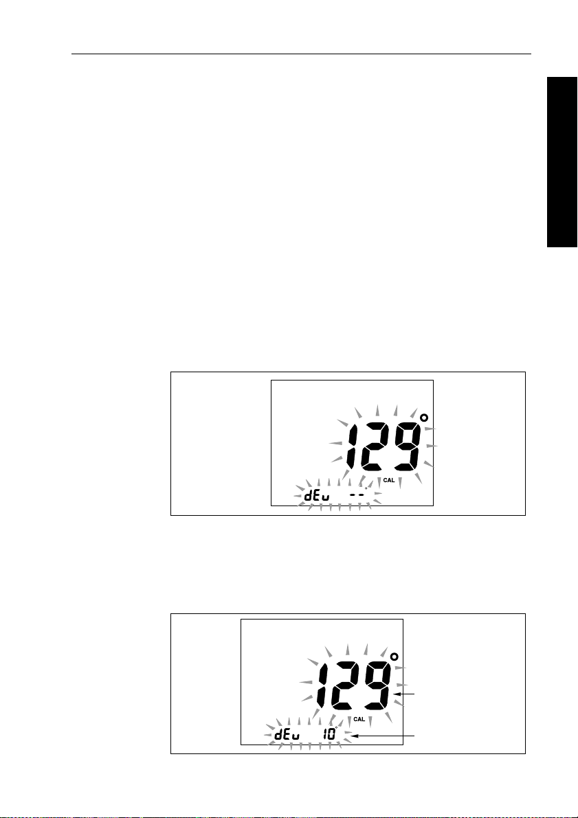
Automatic compass deviation correction
1. With the pilot in S tandby mode, press and hold STBY for
4 seconds.
2. Y ou will then see the current autopilot heading and a
message.
dEv ---
5 Commissioning the Autopilot
D920-1a
3. Start turning the boat in slow circles (with the boat’s speed below
2 knots). Y ou will ne ed to complete up to 2 circles, taking at least
3 minutes to complete each 360°.
4. Continue slowly turning the display shows the amount of
deviation the autopilot has corrected.
Current compass heading
Deviation present
D920-2a
Page 53

48 RayPilot 650 Control Unit - Owner’s Handbook
Note: If the deviation figure exceeds 15° or the displ ay shows no
deviation value, the compass is being affected by ferrous objects on
your boat. You should move the compass to a better location. Higher
deviation figures are acceptable on steel boats.
Aligning the compass heading
1. Once the deviation is displayed, manually steer the boat on a
steady course at a speed which enables you to hold that course.
5 Commissioning the Autopilot
2. Use the course change knob to adjust the displayed heading until
it matches the boat’s steering compass or a known transit bearing.
3. Press and hold
and save the new compass settings.
Note: T o exit without saving changes, press
Adjusting the heading alignment
If you experience difficulties with compass alignment, you can check
the compass alignment after completing the deviation correction
procedure (swinging the compass). After completing the initial
compass calibration, you can make further adjustments to the
alignment without swinging the compass again.
Although the compass calibration removes most of the alignment
error, small errors (o f the order of a few degrees) will probably
remain. These will vary depending on the heading.
Ideally, yo u should check the heading reading against a number of
known headings, plot a deviation curve, and determine the heading
alignment value that will give the lowest average alignment error.
Y ou can then enter this value on the Heading Alignment screen, as
described above.
STBY for 2 seconds to exit Compass C alibration
STBY momentarily.
If the average heading error is more than 5°, you should perform the
compass deviation correction procedure again, circling more slowly
and in more favorable conditions.
Further adjustments to heading alignment
If the heading alignment requires further adjustment after the seatrial:
1. Enter Compass Calibration by pressing
2. Use the course change knob to adjust the displayed heading until
it matches the boat’s steering compass or a known transit bearing.
3. Press
STBY for 2 second to save changes and return t o Standby .
STBY for 4 seconds.
Page 54

Chapter 5: Commissioning the Autopilot 49
Adjusting autopilot settings
The next stage of the seatrial is to set key autopilot parameters that
affect the autopilot’s steerin g charac terist ics.
Y ou need to manually adjust the rudder gain, counterrudder and
AutoTrim setting s, based on your observations of the boat’s
performance under autopilot control.
Adjust these settings when motoring your boat at cruising speed.
On sail boats, repeat if necessary under sail to optimize the pilot.
Checking autopilot operation
Before manually adjusting any of these settings, we recommend that
you familiarize yourself with basic autopilot operation:
1. Steer onto a compass heading and hold the course steady .
If necessary , control the boat manually for a while to check how
the boat steers.
2. Press
3. Use the course change knob to check how the autopilot alters the
4. Press
AUTO to lock onto t he current heading. The autopilot
should hold a constant heading in calm sea conditions.
course to port and starboard.
Sterndrive systems only: W ith the RayPilot in Auto mode and
clear of obstruction, turn the steering wheel to observe the
manual override (AutoRelease). Repeat two or three times until
you are confident with its operation.
STBY to return to hand steering.
5 Commissioning the Autopilot
Adjusting the rudder gain
Boats can vary widely in their response to helm, and by adjusting the
rudder gain you can change the autopilot’s steering characteristics.
Rudder gain is a measure of how much helm the autopilot applies to
correct course errors – higher settings mean more rudder is appl ied.
Complete the following test to determine whether the rudder gain is
set correctly:
1. Set Response to level 2:
• press the
RESP key fo r 2 seconds, then use the ▲ (NAV),
▼ (LIGHTS) key or course change knob to adjust the setting,
then wait for five second to return to St andby mode
Page 55

50 RayPilot 650 Control Unit - Owner’s Handbook
2. Sail your boat at cruising speed in clear water:
• you will find it easiest to recognize the steering response in
calm sea conditions where wave action does not mask basic
steering performance
3. Press
AUTO to enter Auto mode, then alter course by 40°:
• if the rudder gain is adjusted correctly, the 40° course change
should result in a crisp turn foll owed by an overshoot of no
more than 5°
• if the rudder gain setting is too high, the 40° course change
5 Commissioning the Autopilot
will result in a distinct overshoot of more than 5° and there
may be a distinct ‘S’ in the course (
A)
Correct this oversteer by reducing the rudder gain setting.
• if the rudder gain is too low , the boat’s performance will be
sluggish – it will take a long time to make the 40° turn and
there will be no overshoot (B)
Correct this understeer by increasing the rudder gain setting.
New
heading
Rudder setting
too low
Rudder setting
too high
B
New
heading
A
New
heading
Correct rudder
setting
T o adjust the default rudder gain:
1. Access the Rudder Gain screen in Calibration mode.
2. Use the
▲ (NAV) and ▼ (LIGHTS) keys or course change knob to
adjust the rudder gain as necessary .
3. Press and hold
4. Press
AUTO to check the autopilot performance in Auto mode.
STBY for 2 seconds to save the changes.
D3262-2
Page 56

Chapter 5: Commissioning the Autopilot 51
Adjusting rudder gain - high speed planing craft
WARNING:
It is particularly important to set rudder gain correctly on high
speed craft. Incorrect adjustment will lead to poor steering
performance and this can be dangerous at high speed.
Adjust rudder gain as follows:
• set the default rudder gain for optimum steering performance at
the boat’s normal cruising speed
• press the
then make temporary adjustments to rudder gain either side of the
calibrated setting to provide optimum autopilot steering
Due to the significant differences in dynamic stability bet ween
planing and non-planing conditions, most hi gh speed boats require
Rudder Gain adjustment when going from planing to displacement
speeds or vice versa. The required adjustment can be achieved
automatically or manually:
Automatic adjustment:
When the autopilot has speed input from a SeaT alk or NMEA speed
instrument, it will automatically adjust rudder gain with boat speed.
After setting the gain at planing speed no further manual ad justment
should be required.
RESP key to access the Rudder Gain screen: you can
5 Commissioning the Autopilot
WARNING:
When speed information is fed to the autopilot via the NMEA
input always check the displayed speed is close to the actual boat
speed before locking the autopil ot onto a heading. Delays in data
transmission could result in the autopilot applying too much
rudder after a large change in boat speed.
Manual adjustment :
If no speed input is available, adjust rudder gain manually via the
RESP key:
1. Speed decr eases from planing to displacement:
• increase rudder gain by 1 or 2 level
2. Speed increases from displ acement to planing:
• decrease rudder gain by 1 or 2 levels
Page 57

52 RayPilot 650 Control Unit - Owner’s Handbook
WARNING:
Manual gain adjustment mu st be made after reducing fr om
planing to displacement speed and before increasing from
displacement to planing speed.
Adjusting the counter rudder
If you intend to use Response level 3 on a T ype 150/4 00
(non-GyroPlus) or T ype 100/300 autopilot system, you will need to
5 Commissioning the Autopilot
adjust the counter rudder . Counter rudder is the amount of rudder the
autopilot applies to try to prevent the boat from yawing of f course.
Higher counter rudder settings result in more rudder being app lied.
T o check the counter rudder setting
1. Set Response to level 3.
2. Sail your boat at cruising speed in clear water
3. Press
AUTO to switch the autopilot to Auto mode, then make a
90° course change:
• when gain and counter rudder are both set correctly , the boat
performs a smooth continuous turn with min imal overshoot
• if the counter rudder is too low , the boat will still overs hoot
• if counter rudder is too high, the boat will ‘fight’ the turn and
make a series of short, sharp turns: this resu lts in a very
‘mechanical’ feel as the boat changes course
T o adjust the counter rudder:
1. Access the Counter Rudder screen in Calibration mode.
2. Use the
to adjust the counter rudder .
3. Press and hold
4. Press
The pilot is now cali brated an d ready f or use.
▲ (NAV) and ▼ (LIGHTS) keys or course change knob
STBY for 2 seconds to save the changes.
AUTO to check the autopilot performance in Auto mode.
Further adjustments
Over time you may need to repeat these adjustments over a range of
sea conditions and headings to achieve good overall performance.
Y ou may also need to adjust the AutoTrim setting. AutoTrim
determines how quickly the autopilot applies ‘standing helm’ to
correct for trim changes (caused, for example, by changes in the
wind load on the sails or superstructure, o r an imbalance of engines).
Page 58

Chapter 5: Commissioning the Autopilot 53
Gain experience with your autopilot before attempting to adjust t he
AutoTrim setting. On sail bo ats you can only evaluate the effect of
AutoTrim while under sail.
Increasing the AutoTrim level reduces the time the autopilot takes to
get back onto the correct course, but makes the boat less stable:
• if the autopilot gives unstable course keeping and the bo at
‘snakes’ around the desired course, decrease the AutoTrim level
• if the autopilot hangs off cours e for excessive periods of time,
increase the AutoT rim lev el
If you need to adjust AutoTrim, go up o ne level at a time and use the
lowest acceptable value. The possible settings range from
trim correction) to
1. Access the AutoTrim
2. Use the
to adjust the AutoTrim level.
3. Press and hold
4. Press
AUTO to check the autopilot performance in Auto mode.
4 (fastest trim correction). T o adjust the AutoTrim:
screen in Calibration mode.
▲ (NAV) and ▼ (LIGHTS) keys or course change knob
STBY for 2 seconds to save the changes.
OFF (no
5 Commissioning the Autopilot
Page 59

54 RayPilot 650 Control Unit - Owner’s Handbook
5 Commissioning the Autopilot
Page 60

Chapter 6: Adjusting Autopilot Settings 55
Chapter 6: Adjusting Autopilot Settings
This chapter explains all of the calibration settings you can adjust on
the autopilot system. You will have adjusted many of these settings
when commissioning the system (see Chapter 5), and they should not
require further adjustment.
The order of the calibration screens and the options you can select
depend on the type of course computer connected to your RayPilot:
• for information about Calibration mode with T ype 150/ 150G
and Ty pe 400/400G course computers, refer to page 56
• for information about Calibration mode with T ype 100/ 300
course computers, refer to page 66
Note: C omplete the procedures described in Chapter 5 before
adjusting any calibration settings.
6 Adjusting Autopilot Settings
Page 61

56 RayPilot 650 Control Unit - Owner’s Handbook
6.1 Type 150/150G and 400/400G course computers
Accessing Calibration mode
Y ou can only access Calibration mo de from Standby mode:
1. With the autopilot in S tandby mode, press and hold
16 seconds until the display shows a small
2. Press
3. Press
4. Press
5. When you reach an item you wish to adjust, use the
AUTO and STBY together: you will then see a large CAL
message.
AUTO to enter Calibration mode.
AUTO to scroll through the various calibration screens.
CAL legend.
▼ (LIGHTS) keys or course change knob to change the value.
6. When you have made all the required changes, press and hold
STBY for 2 seconds to exit Cali bration mode and save changes.
STBY for
▲ (NAV) and
Note: To exit Calibr ation mode without saving changes, press
momentarily.
STBY
Calibration screens
6 Adjusting Autopilot Settings
When you use the RayPilot 650 with a T ype 15 0/150G or
T ype 400/400G course computer , the calibration screens appear in
the following order:
Calibration lock (CAL LoC)
This screen controls whether it is possible to access the compass
deviation and alignment screens.
Options
0 Calibration lock off – compass deviation can be
accessed (default)
1 Calibration lock on – compass deviation cannot be
accessed
Page 62

Chapter 6: Adjusting Autopilot Settings 57
Vessel type (vES tYP)
V essel type shou ld be set when commissioning the autopilot.
Options
1 Displacement powerboat
2 Semi-displacement powerboat
3 Planing powerboat
4 Planing powerboat with I/O drive (stern drive)
5 Work boat (150/150G and 400/400G only)
6 Sail boat (150/150G and 400/400G only)
Note: When you s elect the vessel type, the autopilot will set
appropriate defaults for several other calibration settings. Refer to
the table on page 64 for default values.
Drive type (drv oPt)
The drive type setting controls how the autopilot drives the steering
system. The drive type should be set when commissioning the
autopilot.
6 Adjusting Autopilot Settings
Options
3 Linear drive, rotary drive or I/O (stern) drive
4 Hydraulic pump or hydraulic linear drive
5 Constant running hydraulic pump solenoids
Align rudder (rUd Add)
Use the screen to center the rudder bar display after installing the
autopilot system.
Screen text Range
rUd Add -7° to +7° in 1° steps
Page 63

58 RayPilot 650 Control Unit - Owner’s Handbook
Rudder limit (rUd StP)
Use the rudder limit screen to set the limits of autopilot rudder control
just inside the mechanical end stops. This will avoid pu tting the
steering system under unnecessary load. Y o u should adjust this
setting when commissioning the autopilot.
Screen text Range
rUd StP 10° to 40° in 1° steps
Rudder gain (rUd LEv)
This screen determines the default rudder gain setting. Rudder gain is
a measur e of how mu ch helm th e autopil ot will apply to correct
course errors. The higher the setting the more rudder will be applied.
The default rudder gain is set during the initial seatrial. Y ou can make
temporary changes to this rudder gain value during normal operation.
Screen text Range
rUd LEv 1 to 9
6 Adjusting Autopilot Settings
Counter rudder (rtE LEv)
Counter rudder is the amount of rudder the autopilot appli es to try to
prevent the boat from yawing off course. Higher counter ru dder
settings result in more rudder being applied. The default rudder gain
is set during the initial seatrial.
Screen text Range
rtE LEv 1 to 9
Rudder damping (rUd dPG)
Adjust the rudder damping value if the autopilot ‘h unt s’ when trying
to position the rudder . Increasing the rudder damping value reduces
hunting.
Screen text Range
rUd dPG 1 to 9
Page 64

Chapter 6: Adjusting Autopilot Settings 59
AutoTrim (tr LEv)
The AutoTrim setting determines the rate at which the autopilot
applies ‘standing helm’ to correct for trim changes caused by varying
wind loads on the sails or superstructure.
The defau lt AutoT rim is se t when comm issioning t he autopilo t.
If you need to change the setting, increase th e AutoTrim one level at a
time and use the lowest acceptable value:
• decrease the AutoTrim level if the autopilot gives unstable course
keeping or excessive drive activity with a change in the heel angle
• increase the AutoTrim level if the autopilot reacts slowly to a
heading change due to a change in the heel angle
• if the AutoTrim level is too high, the boat will be less stable and
snake around the desired course
Note: T ype 150G/400G autopilots have a ‘FastTrim’ feature within
AutoTrim. Select
Setting Effect
OFF No trim correction
1 Slow trim correction
2 Medium trim correction
3 Rapid trim correction
4 Very rapid trim correction
OFF to turn off FastTrim as well as AutoTrim.
6 Adjusting Autopilot Settings
Response level (rES)
This is the default autopilot response level. The response level
controls the relationship between course keeping accuracy and the
amount of helm/drive activity . Y ou can make temporary changes to
response during normal operation.
Page 65

60 RayPilot 650 Control Unit - Owner’s Handbook
Type 150G/400G autopilot systems
T ype 150G/400G autopilot systems have 9 possibl e response levels.
Options
1 to 9 • level 1 gives the least pilot activity to conserve power, but
may compromise short-term course-keeping accuracy
• levels 4 to 6 should give good course keeping with crisp,
well controlled turns under normal operating conditions
• level 9 gives the tightest course keeping and greatest
rudder activity, but may lead to a rough passage in open
waters as the autopilot may ‘fight’ the sea
Type 150/400 autopilot systems
T ype 150/400 (non-GyroPlus) and T ype 100 /300 autopilot systems
have 3 possible response levels:
Setting
1
6 Adjusting Autopilot Settings
2
3
AutoSeastate on (Automatic deadband)
• autopilot to gradually ignores repetitive boat movements
and only react to true variations in course
• provides the best compromise between power
consumption and course keeping accuracy
AutoSeastate off (minimum deadband)
• provides tighter course keeping
• increased power consumption and drive unit activity
AutoSeastate off + counter rudder yaw damping
• provides tightest possible course keeping by introducing
counter rudder yaw damping
Turn rate limit (trn rtE)
Note: No t available if vessel type = 6 (Sail boat).
This limits your boat’s rate of turn under autopilot control.
Screen text Range
trn rtE 1° to 30° per second in 1° steps
Page 66
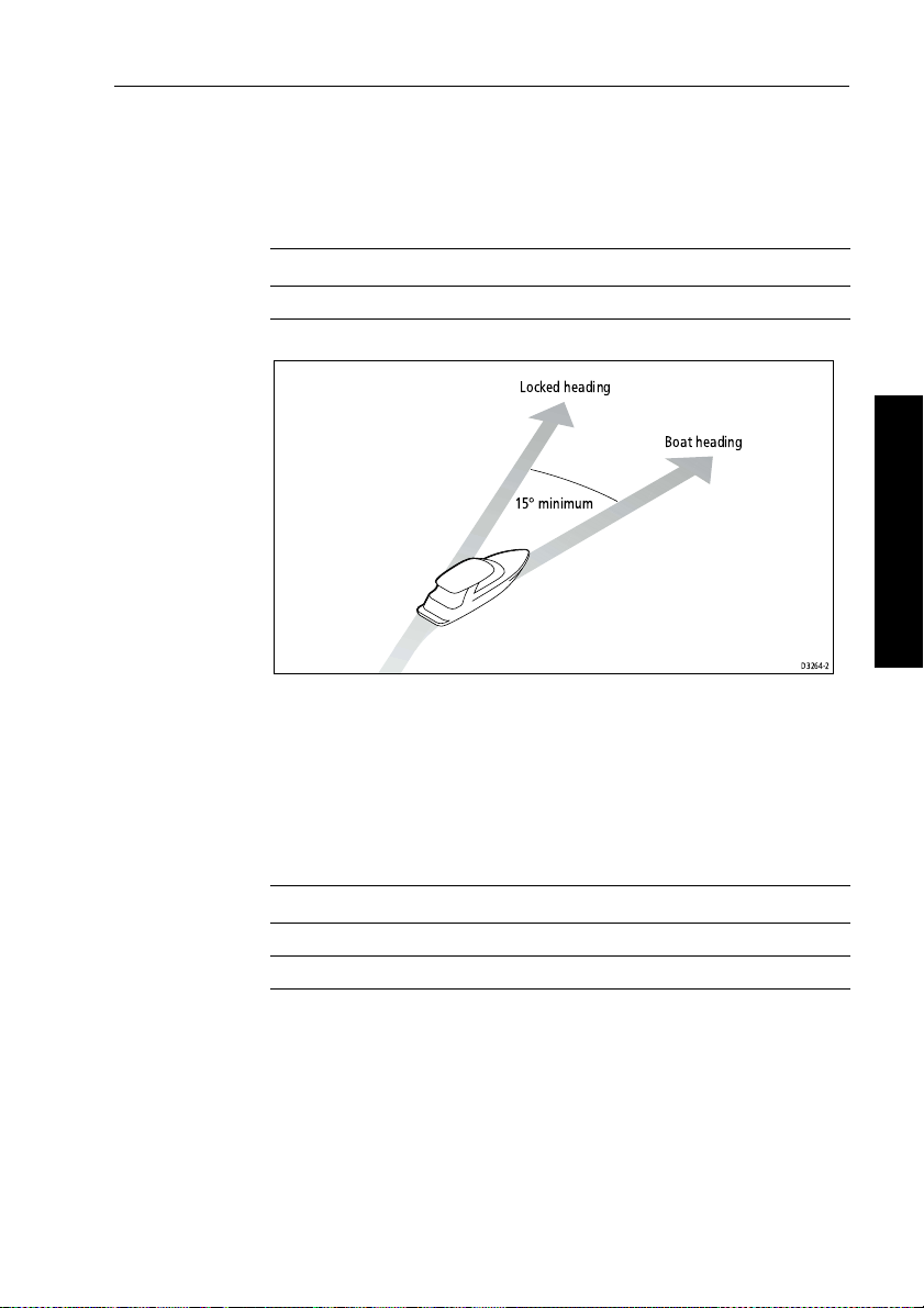
Chapter 6: Adjusting Autopilot Settings 61
Off course warning angle (oFF CrS)
This screen determines the angle used by the Off Course warning.
The Off Course warning operates if the pilot strays of f course by more
than the specified angle for more than 20 seconds.
Screen text Range
oFF CrS 15° to 40° in 1° steps
Locked heading
Boat heading
15°minimum
D3264-2
AutoRelease (I/O drives only) (AUt rLS)
Note: Onl y available if vessel type = 4 (Stern drive).
If the vessel type is set to
AutoRelease screen
emergency manual over-ride in situation s when you need to avoid an
obstacle at the last moment.
Screen text Range
0 AutoRelease off
1 AutoRelease on (default for stern drives)
4 (I/O or stern drive), you will see the
set to 1 (on) as a default. AutoRelease provides
6 Adjusting Autopilot Settings
Page 67

62 RayPilot 650 Control Unit - Owner’s Handbook
WindTrim (wind response) (unE tC)
Note: Onl y available if vessel type = 6 (sail boa t) on Type 150/150G
or Type 400/400G.
WindT rim (wind response) controls how quickly t he autopilot
responds to changes in the wind direction. Higher wind t rim settings
will result in a pilot that is more responsive to wind chan ges.
Screen text Options
unE tC Range = 1 to 9
Lower values (1 to 3) = autopilot responds to longer term
wind changes (less pilot activity)
Typical values = 4 to 6
Higher values (7 to 9) = autopilot responds to shorter term
wind changes (more pilot activity)
Cruise speed (CSE SPd)
Set the cruise speed to the boat’s typical cruising speed. If both the
boat’s speed through the water and speed over ground are unavai lable
via SeaTalk or NMEA, the autopilot will use this default cruise speed
6 Adjusting Autopilot Settings
when computing course changes.
Screen text Range
CSE SPd 4 to 60 knots
AutoAdapt (AUt AdP)
The AutoAdapt feature allows the autopilot to compensate for
heading errors at higher latitudes, which are caused by the increasing
dip of the earth’s magnetic field. The increased dip has the effect of
amplifying rudder response on northerly h eadings in the northern
hemisphere, and on southerly headings in the southern hemis phere.
Options
0FF AutoAdapt off
1 AudoAdapt compensation on – Northern hemisphere
2 AutoAdapt compensation on – Southern hemisphere
Note: If you set AutoAdapt to 1 or 2, you then need to enter y our
current latitude in the next screen (Latitude), so that the autopilot can
provide accurate course keeping by automatically a djusting the
Page 68

Chapter 6: Adjusting Autopilot Settings 63
rudder gain depending on the heading. If you have a GPS connected,
the autop ilot will ta ke latitude informatio n from the G PS.
North
without
North
with
compensation
compensation
D3263-2P
Latitude (LAt)
The RayPilot only displays thi s screen if you have set AutoAdapt to
1 or 2. Use the ▲ (NAV) and ▼ (LIGHTS) keys or course change
knob to set the value to your boat’s current latitude, to the nearest
degree.
Note: If valid latitude data is available via SeaTalk or NMEA, t he
RayPilot will use this data instead of the calibration value.
6 Adjusting Autopilot Settings
Screen text Range
LAt 0° to 80° in 1° steps
Magnetic variation (vAr)
If required, set this value to the level of magnetic variation present at
your boat’s current position – indicated as east or west. The autopilot
sends this variation setting to other instrument s on the SeaT alk
system, and it can be updated by other SeaT alk instruments.
Screen text Options
OFF Default setting = OFF
vAr EAST/ vAr WEST 30°EAST(-30°) to 30° WEST (+30°) in 1° steps
Page 69

64 RayPilot 650 Control Unit - Owner’s Handbook
Calibration defaults: Types 150/150G & 400/400G
Calibration
setting
Vessel type
Factory default
Displacement
Semi Displacement
Planing
Stern drive (I/O)
Work boat
Calibration lock0000000
Vessel type0123456
Drive type3444353
Rudder alignment0000000
Rudder limit 30 30 30 20 20 30 30
Rudder gain4544452
Counter rudder4355522
Rudder damping2222232
AutoTrim2233321
Response: with G
6 Adjusting Autopilot Settings
non-G52
5
2
5
2
5
2
5
2
5
2
Turn rate limit555555--Off course angle20202020202020
AutoRelease OFF --- --- --- ON --- --Wind Trim 5 --- --- --- --- --- 5
Cruise speed88882088
AutoAdapt nth nth nth nth nth nth nth
Latitude 0000000
Variation 0000000
Sail boat
5
2
Page 70

Chapter 6: Adjusting Autopilot Settings 65
Calibration options: Types 150/150G & 400/400G
Calibration
setting
Vessel type
Factory default
Displacement
Semi Displacement
Planing
Stern drive (I/O)
Work boat
Sail boat
Calibration lock 0 = OFF, 1 = ON
Vessel type 1 = DISPLACE, 2 = SEMI DISPLACE, 3 = PLANING, 4 = STERN DRV,
5 = WORK BOAT, 6 = SAIL BOAT
Drive type 3, 4, 5
Rudder alignment -7 to +7
Rudder limit 10 to 40
Rudder gain 1 to 9
Counter rudder 1 to 9
Rudder damping 1 to 9
AutoTrim 0 to 4
Response
1 to 9 (Type 150G/400G)
1 to 3 (Type 150/400)
Turn rate limit 1 to 30
Off course angle 15 to 40
AutoRelease OFF, ON
Wind Trim 1 to 9
Cruise speed 4 to 60
AutoAdapt OFF, nth, Sth
Latitude 0 to 80
Variation -30 to +30
You r se tti ngs
6 Adjusting Autopilot Settings
Page 71

66 RayPilot 650 Control Unit - Owner’s Handbook
6.2 Type 100/300 course computers
Accessing Calibration mode
Y ou can only access Calibration mo de from Standby mode:
1. With the autopilot in S tandby mode, press and hold
16 seconds until the display shows a small
2. Press
3. Press
4. When you reach an item you wish to adjust, use the
AUTO and STBY together to enter Calibration mode.
AUTO to scroll through the various calibration screens.
CAL legend.
▼ (LIGHTS) keys or course change knob to change the value.
5. When you have made all the required changes, press and hold
STBY for 2 seconds to exit Cali bration mode and save changes.
Note: To exit Calibr ation mode without saving changes, press
momentarily.
Calibration screens
When you use the RayPilot 650 with a T ype 10 0/300 course
6 Adjusting Autopilot Settings
computer, the calibration screens appear in the following order:
Vessel type (vES tYP)
V essel type shoul d be set when commissioning the autopilot.
STBY for
▲ (NAV) and
STBY
Options
1Displacement
2 Semi-displacement
3 Planing
4 Boat with I/O drive (stern drive)
Note: When you select the vessel type, the autopilot will set
appropriate defaults for several other calibration settings.
Page 72

Chapter 6: Adjusting Autopilot Settings 67
Calibration lock (CAL LoC)
This screen controls whether it is possible to access the compass
deviation and alignment screens.
Options
0 Lock off: Compass Calibration can be accessed
1 Lock on: Compass Calibration cannot be accessed
Rudder gain (rUd LEv)
This screen determines the default rudder gain setting. Rudder gain is
a measure of how much helm the autopilot will apply to correct
course errors. The higher the setting, the more rudder will be applied.
Y ou should adjust this setting when commissioning the autopilot.
Y ou can make temporary changes to this ru dder gain value during
normal operation.
Screen text Range
rUd LEv 1 to 9
Counter rudder (rtE LEv)
Counter rudder is the amount of rudder the autopil ot applies to try to
prevent the boat from yawing off course. Higher counter rudder
settings result in more rudder being applied. You should set the
default counter rudder when commissioning the autopilot.
6 Adjusting Autopilot Settings
Screen text Range
rtE LEv 1 to 9
Align rudder (rUd Add)
Use this screen to center the rudder bar display after installing the
autopilot system.
Screen text Range
rUd Add -7° to +7° in 1° steps
Rudder limit (rUd StP)
Use the rudder limit screen to set the limits of autopilot rudder control
just inside the mechanical end stops. This will avoid putting the
Page 73

68 RayPilot 650 Control Unit - Owner’s Handbook
steering system under unnecessary load. Y ou should adjust this when
commissioning the autopilot.
Screen text Range
rUd Add 15° to 30° in 1° steps
Turn rate limit (trn rtE)
This limits your boat’s rate of turn under autopilot control.
Screen text Range
trn rtE 5° to 20° per second in 1° steps
Cruise speed (CSE SPd)
Set the cruise speed to the boat’s typical cruising speed. If both the
boat’s speed through the water and speed over ground are unavai lable
via SeaTalk or NMEA, the autopilot will use this default cruise speed
when computing course changes.
Screen text Range
6 Adjusting Autopilot Settings
CSE SPd 4 to 60 knots
Off course warning angle (oFF CrS)
This screen determines the angle used by the Off Course warning.
The Off Course warning operates if the pilot strays off course by more
than the specified angle for more than 20 seconds.
Screen text Range
oFF CrS 15° to 40° in 1° steps
AutoTrim (tr LEv)
The AutoTrim setting determines the rate at which the autopilot
applies ‘standing helm’ to correct for trim changes caused by varying
wind loads on the sails or super structure.Y ou should set t he default
AutoTrim after commissioning the autopilot.
Setting Effect
OFF No trim correction
1 Slow trim correction
Page 74

Chapter 6: Adjusting Autopilot Settings 69
Setting Effect
2 Medium trim correction
3 Rapid trim correction (default)
4 Very rapid trim correction
Power steer (JoY)
If you have a joystick connected to your T ype 100/300 autopi lot
system, use this screen to select the required joystick mode of
operation (see table).
Options
OFF Power steer off
1 1 = Proportional power steer
Proportional power steer applies rudder in proportion to
joystick movement – the further the joystick is held over,
the greater the applied rudder.
2 2 = Bang-bang power steer
Bang-bang power steer applies continuous rudder in the
direction of the lever movement – to improve control, the
speed of rudder movement changes with the angle of the
lever. For maximum speed, push the lever ha rdover. If you
return the lever to the center position, the rudder will
remain in its current position.
6 Adjusting Autopilot Settings
Drive type (drv oPt)
The drive type setting controls how the autopilot drives the steering
system. Y ou should se t the drive type when commissioning the
autopilot.
Options
1 and 2 Not used
3 Linear drive, rotary drive or I/O (stern) drive
4 Hydraulic pump or hydraulic linear drive
5 Constant running hydraulic pump solenoids
Page 75

70 RayPilot 650 Control Unit - Owner’s Handbook
Rudder damping (rUd dPG)
Set this option during the initial dockside checks if the autopilot
‘hunts’ when trying to position t he rudder.
Screen text Range
rUd dPG 1 to 9
Magnetic variation (vAr)
If required, set this value to the level of magnetic variation present at
your boat’s current position – indicated as east or west. The autopilot
sends this variation setting to other instruments on the SeaTalk
system, and it can be updated by other SeaT alk instruments.
Screen text Options
VARIATION Default setting = 0°
vAr EAST/ vAr WEST 30°EAST(-30°) to 30° WEST (+30°) in 1° steps
AutoAdapt (AUt AdP)
6 Adjusting Autopilot Settings
The AutoAdapt feature allows the autopilot to compensate for
heading errors at higher latitudes, which are caused by the increasing
dip of the earth’s magnetic field.
The increased dip has the effect of amplifying rudder resp onse on
northerly headings in the northern hemispher e, and on southerly
headings in the southern hemisphere.
Note: If you set AutoAdapt to
1 or 2, you th en need to enter your
current latitude in the next screen (Latitude), so that the autopilot can
provide accurate course keeping by automatically a djusting the
rudder gain depending on the heading.
Options
OFF AutoAdapt off
1 AudoAdapt compensation on – Northern hemisphere
2 AutoAdapt compensation on – Southern hemisphere
Latitude (LAt)
The RayPilot 650 only displays this screen if you have set AutoAdapt
to
1 or 2. Use the ▲ (NAV) and ▼ (LIGHTS) keys or course change
Page 76

Chapter 6: Adjusting Autopilot Settings 71
knob to set the value to your boat’s current latitude, to the nearest
degree.
Note: If valid latitude data is available via SeaTalk or NMEA, t he
autopilot will use this data instead of the calibration value.
Screen text Range
LATITUDE 0° to 80° in 1° steps
WindTrim (wind response) (unE tC)
Note: Onl y available if vessel type = 1 (displacement) on Type
100/300.
WindT rim (wind response) controls how qu ickly the autopilot
responds to changes in the wind direction.
Screen text Options
WIND TRIM 1 = Normal setting
2 = Faster response for wind shifts
AutoRelease (I/O drives only) (AUt rLS)
Note: Onl y available if vessel type = 4 (Stern drive).
If the vessel type is set to
AutoRelease screen
provides emergency manual over-ride in situations when you need to
avoid an obstacle at the last moment.
4 (I/O or stern drive), you will see the
(AUt rLS) set to ON as a default. AutoRelease
6 Adjusting Autopilot Settings
Screen text Range
AUt rLS ON = AutoRelease on
OFF = AutoRelease off
Response level (rES)
This is the default response setting. The response level contr ols the
relationship between the autopilot’s course keeping accuracy and the
amount of helm/drive activity . Y ou can make temporary changes to
response during normal operation.
Page 77

72 RayPilot 650 Control Unit - Owner’s Handbook
Screen text Options
1
AutoSeastate on (Automatic deadband) = default
• autopilot to gradually ignores repetitive boat movements
and only react to true variations in course
• provides the best compromise between power
consumption and course keeping accuracy
2
AutoSeastate off (minimum deadband)
• provides tighter course keeping
• increased power consumption and drive unit activity
3
AutoSeastate off + counter rudder yaw damping
• provides tightest possible course keeping by introducing
counter rudder yaw damping
6 Adjusting Autopilot Settings
Page 78

Chapter 6: Adjusting Autopilot Settings 73
Dealer Calibration: default settings with Type 100/300
Calibration setting Vessel type
1 = Displacement
2 = Semi Displacement
3 = Planing
4 = Stern drive (I/O)
Vessel type 1234
Calibration lock 0000
Rudder gain 5543
Counter rudder 7775
Rudder alignment 0000
Rudder limit 30303020
Turn rate limit 20 15 15 8
Cruise speed 6 8 15 15
Off course angle 20202020
AutoTrim 2333
Power steer OFF OFF OFF OFF
Drive type 3443
Rudder damping 2222
Variation OFF OFF OFF OFF
AutoAdapt NORTH NORTH NORTH NORTH
Latitude 0000
Wind Trim
(displacement only)
AutoRelease
(stern drives only)
1 --- --- ---
--- --- --- ON
Response 1111
Note: Information applies to Type 100/300 Course Computers with Version 15 software.
You r se tti ngs
6 Adjusting Autopilot Settings
Page 79

74 RayPilot 650 Control Unit - Owner’s Handbook
6 Adjusting Autopilot Settings
Page 80

Limited Warranty Certificate
Raymarine warrants each new Light Mar ine/Dealer Distributor Product to be of good materials and
workmanship, and will repair or exchange any parts proven to be defective in material and
workmanship under no rmal use for a period of 2 years/24 mon ths from date of sale to end user , except
as provided below.
Defects will be corrected by Raymarine or an authorized Raymarine dealer. Raymarine will, except
as provided below , accept labor cost for a period of 2 years /24 months from the date of sale to end user .
During this period, except for cer tain products, travel costs (auto milea ge and tolls) up to 100 round
trip highway miles (160 kilometres) and travel time of 2 hours, will be assumed by Raymarine only
on products where proof of installation or commission by authorized serv ice agents, can be shown.
Warranty Limitations
Raymarine W arranty policy does not apply to equ ipment which has been subjected to ac cident, abuse
or misuse, shipping damage, alteration s, corrosion, incorr ect and/or non-auth orized service, or
equipment on which the serial number has been altered, m utilated or removed.
Except where Raymarine or its authorized dealer has performed the installation, it assumes no
responsibility for damage incurred during installation.
This W arranty does not cover routin e system checkouts or alignment/calibration, unless required by
replacement of part(s) in the area being aligned.
A suitable proof of pu rchase, showing d ate, place, and serial number must be made available to
Raymarine or authorized service agent at the time of request for W arranty service.
Consumable items, (such as: Char t paper, lamps, fus es, batteries, styli, stylus/drive belts, radar mixer
crystals/diodes, snap-in impeller carriers, impellers, impeller bearings, and impeller shaft) are
specifically excluded from this Warranty .
Magnetrons, Cathode Ray Tubes (CR T), TFT Liquid Crystal Displays (LCD) and cold cathode
fluorescent lamps (CCFL), hailer horns and transducers are warranted for 1 year/12 months from date
of sale. These items must be returned to a Raymarine facility.
All costs associated with transducer replacement, other than the cost of the transducer itself, are
specifically excluded from this Warranty .
Overtime premium labor portion of services outside of normal working h ours is not covered by this
W arranty.
Travel cost allowance on certa in products with a suggested retail p rice below $2500 .00 is not
authorized. When/or if repairs are ne cessary , these products must be f orwarded to a Raymarine
facility or an authorized dealer at owner’s expense will be returned via surface carrier at no cost to the
owner.
Travel costs other than auto mileage, tolls and two (2) hours travel time, are specifically excluded on
all products. T ravel costs which are exc luded from the coverage of this W arranty in clude but are no t
limited to: taxi, launch fees, aircraft rental, subsistence, customs, shipp ing and communication
charges etc. T ravel cost s, mileage and time, in excess to that allo wed must have prior appr oval in
writing.
TO THE EXTENT CONSISTENT WITH ST ATE AND FEDERAL LAW:
(1) THIS W ARRANTY IS STRICTLY LIMITED TO THE TERMS INDICA TED HEREIN, AND
NO OTHER WARRANTIES OR REMEDIES S HALL BE BIND ING ON RA YM ARINE
INCLUDING W ITHOUT LIMI T A TI ON ANY WARRANTIES OF MER CHANT ABL E OR
FITNESS FOR A P ARTICULAR PURPOSE.
(2) Raymarine shall not be liable for any incidental, consequential or special (including punitive or
multiple) damages.
All Raymarine products sold or provided her eunder are merely aids to navigation. It is the
responsibility of the user to exercise discretion and proper navigational skill independent of any
Raymarine equipment.
Document number: 84064-8
April 2001
Page 81

Factory Service Centers
United States of America UK, Europe, Middle East, Far East
Raymarine Inc
22 Cotton Road, Unit D
Nashua, NH 03063-4 219, USA
Telephone: +1 603 881 5200
Fax: +1 603 864 4756
www.raymarine.com
Sales & Order Services
Telephone: +1 800 539 5539 Ext. 2333 or
Technical Support
Telephone: +1 800 539 5539 Ext. 2444 or
Email: techsupport@raymarine.com
Product Repair Center
Telephone: +1 800 539 5539 Ext. 2118
+1 603 881 5200 Ext. 2333
+1 603 881 5200 Ext. 2444
Raymarin e Ltd
Anchorage Pa rk, Portsmouth
PO3 5TD, England
Telephone: +44 (0)23 9269 3611
Fax: +44 (0)23 9269 4642
www.raymarine.com
Customer Support
Telephone: +44 (0)23 9271 4713
Fax: +44 (0)23 9266 1228
Email: techsupport@ raymarine.com
Stick barcode label here
Purchased f rom Purchase date
Dealer address
Installed by Installation date
Commissioned by
Commissioning date
Owner’s name
Mailing address
This portion should be comple ted and retained by the owner.
 Loading...