

Raymarine RAYNAV 780 LORAN C User Manual

Distributed by
Any reference to Raytheon or
RTN in this manual should be
interpreted as Raymarine.
The names Raytheon and RTN
are owned by the
Raytheon Company.
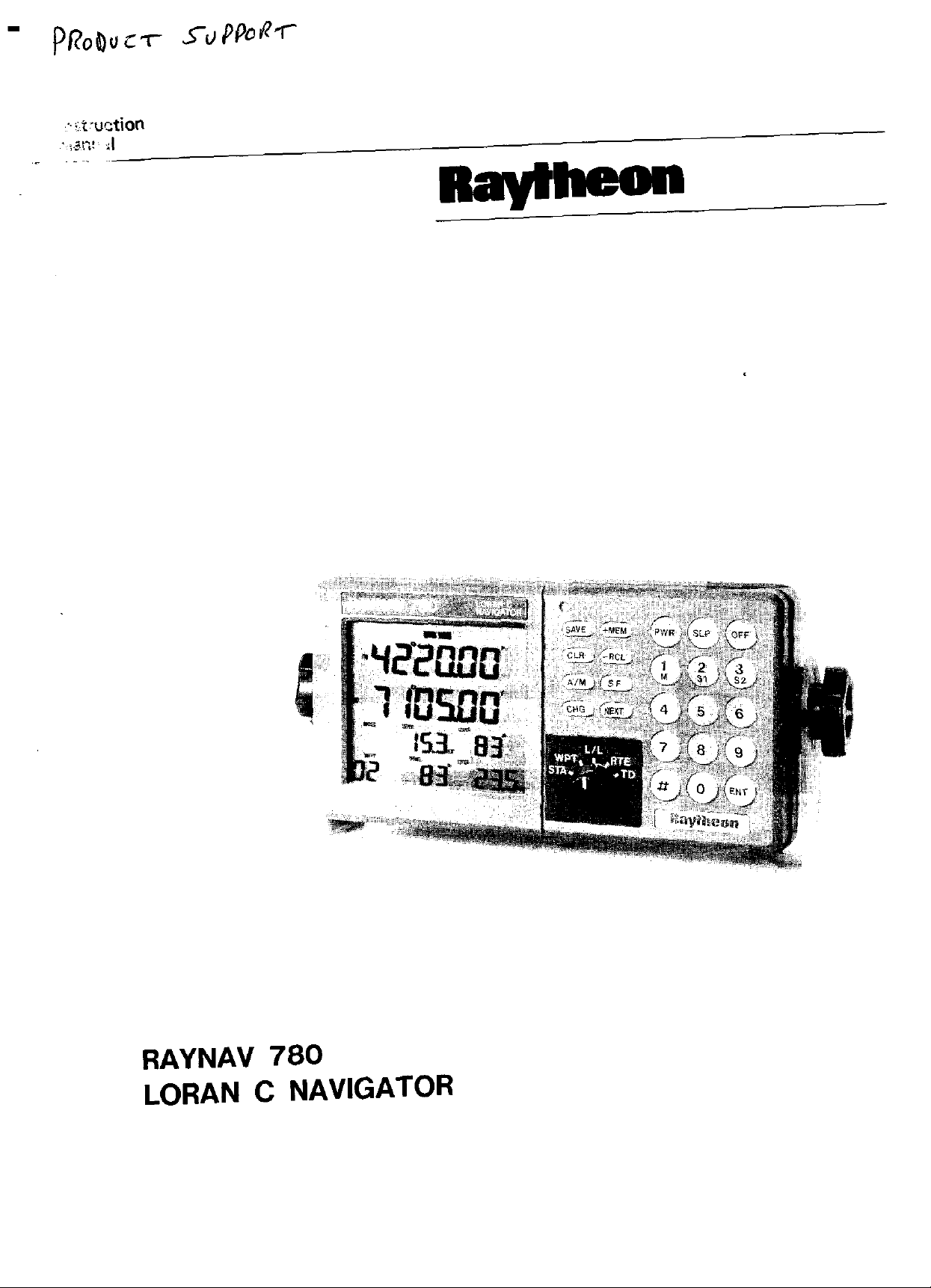
RAYNAV 780
LORAN C NAVIGATOR

“IMPORTANT NOTICE”
This device is only an aid to navigation. Its accuracy can be affected by many
factors including equipment failure or defects, environmental conditions, and
’ improper handling or use. It is the user’s responsibility to exercise common pru-
dence and navigational judgment. This device should not be relied on as a substitute.for such prudence and judgment.
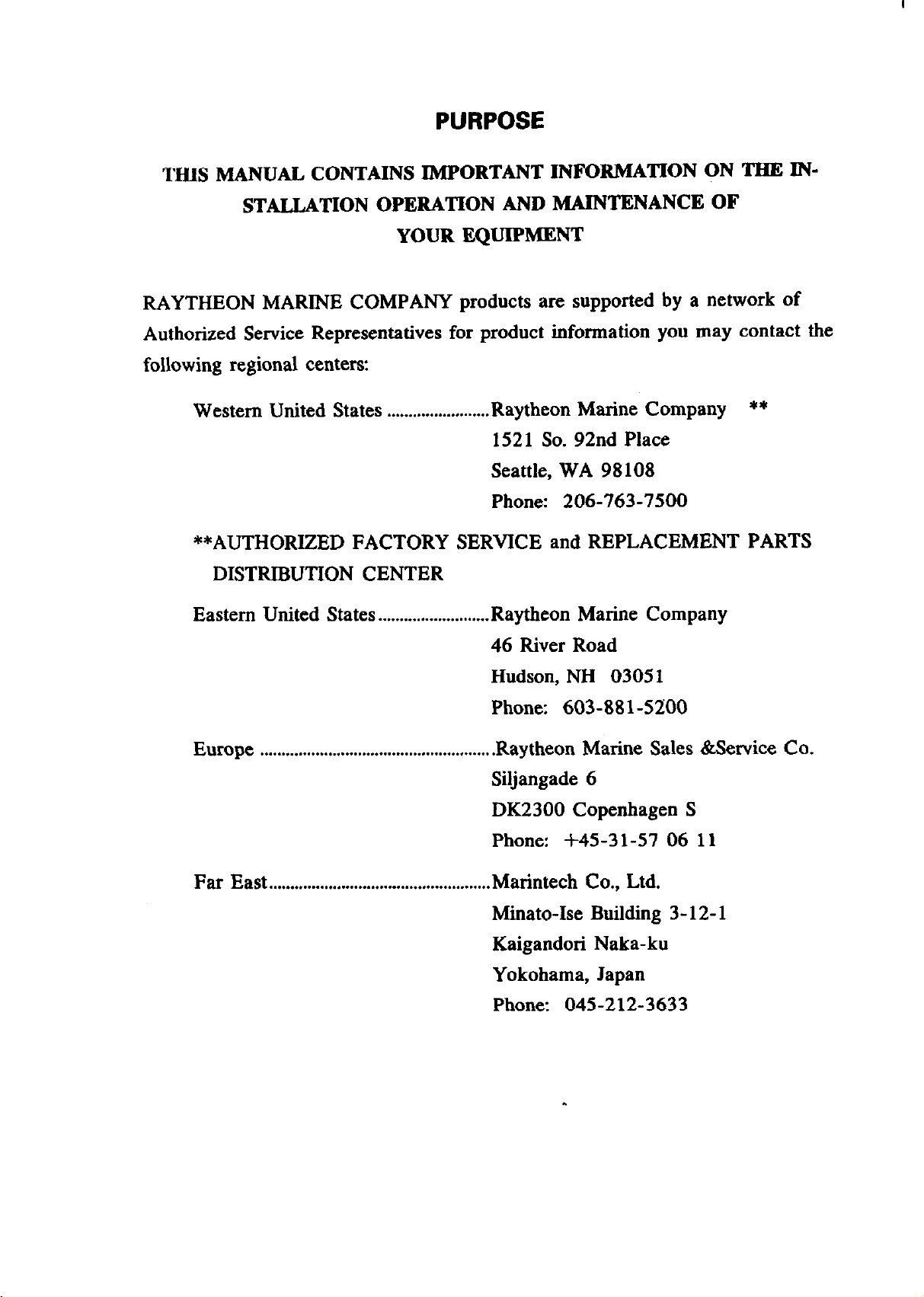
PURPOSE
THIS MANUAL CONTAINS IMPORTANT INFORMATION ON THR IN-
STALLATION OPERATION AND MAINTENANCE OF
YOUR EQUIPMENT
RAYTHEON MARINE COMPANY products are supported by a network of
Authorized Service Representatives for product information you may contact the
following regional centers:
Western United States . . . . . . . . . . . . . . . . . . . . . . . . Raytheon
152 1 So. 92nd Place
Seattle, WA 98108
Phone: 206-763-7500
**AUTHORIZED FACTORY SERVICE and REPLACEMENT PARTS
DISTRIBUTION CENTER
Eastern United States
Europe . . . . . . . . . . . . . . . . . . . . . . . . . . . . . . . . . . . . . . . . . . . . . . . . . . . . . .
. . . . . . . . . . . . . . . . . . . . . . . . . . Raytheon
46 River Road
Hudson, NH 03051
Phone: 603-881-5200
.Raytheon Marine Sales &Service Co.
Siljangade 6
DK2300 Copenhagen S
Phone: +45-31-57 06 11
Marine Company **
Marine Company
Far East . . . . . . . . . . . . . . . . . . . . . . . . . . . . . . . . . . . . . . . . . . . . . . . . . . . . Marintech
Minato-Ise Building 3- 12- 1
Kaigandori Naka-ku
Yokohama, Japan
Phone: 045-212-3633
Co., Ltd.

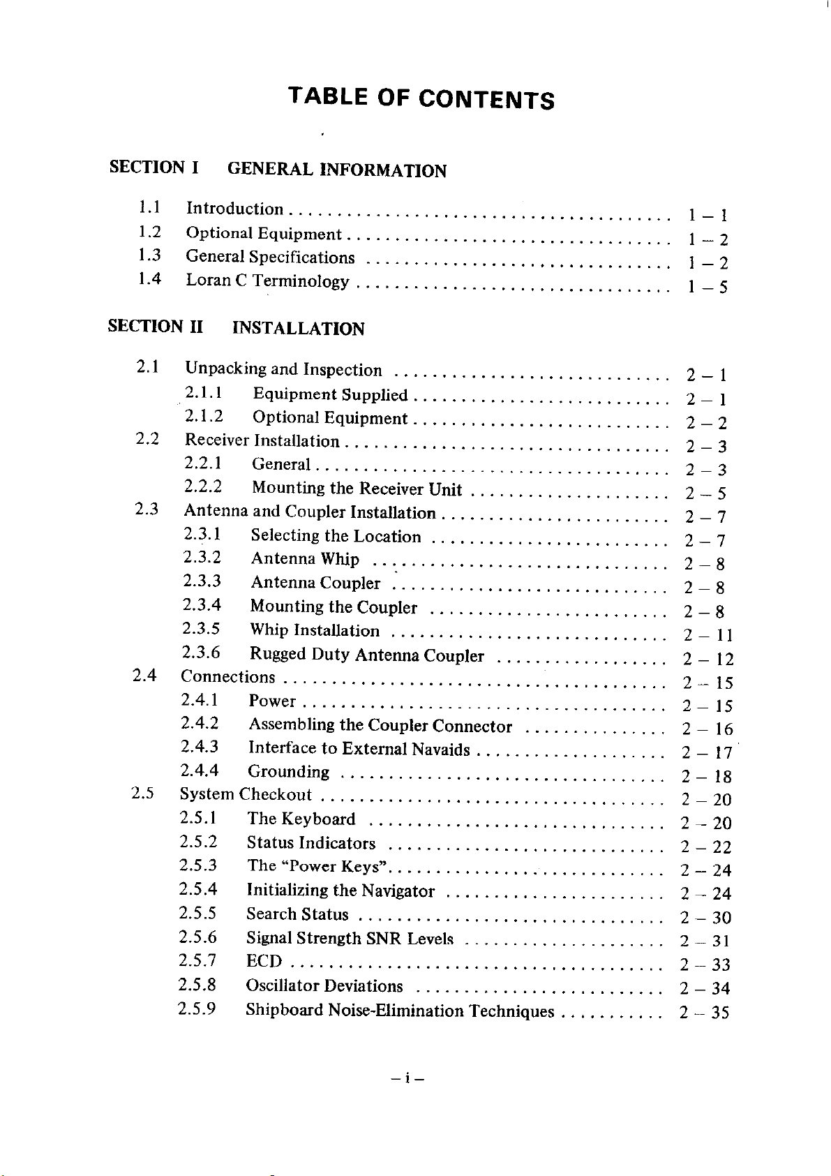
TABLE OF CONTENTS
SECTION I
1.1
1.2
1.3
1.4
Introduction
Optional Equipment.
General Specifications
LoranC Terminology
SECTION II
2.1
Unpacking and Inspection
2.1.1
“2.1.2
2.2
Receiver Installation.
2.2.1
2.2.2
2.3
Antenna and Coupler Installation
2.3.1
2.3.2
2.3.3
2.3.4
2.3.5
2.3.6
2.4
Connections
2.4.1
2.4.2
2.4.3
2.4.4
2.5
System Checkout
2.5.1
2.5.2
2.5.3 The “Power Keys”.
2.5.4 Initializing the Navigator
2.5.5 Search Status
2.5.6 Signal Strength SNR Levels
2.5.7 ECD
2.5.8
2.5.9
GENERAL INFORMATION
........................................
.................................
................................
.................................
INSTALLATION
.............................
Equipment Supplied.
Optional Equipment.
................................. 2 - 3
.......................... 2 - 1
.......................... 2 - 2
General .....................................
Mounting the Receiver Unit
Selecting the Location
Antenna Whip
Antenna Coupler :.
............................... 2 - 8
...........................
Mounting the Coupler
Whip Installation
.............................
.....................
........................ 2 - 7
......................... 2 - 7
......................... 2 - 8
Rugged Duty Antenna Coupler
........................................
Power ......................................
Assembling the Coupler Connector
Interface to External Navaids
Grounding
TheKeyboard
Status Indicators
..................................
....................................
...............................
.............................
............................
................................
....................
.......................
.....................
.......................................
Oscillator Deviations
..........................
Shipboard Noise-Elimination Techniques
..................
...............
...........
1 - 1
1 - 2
1 - 2
1 - 5
2 - 1
2-3
2 - 5
2 - 8
2 - 11
2 - 12
2 - 15
2-1.5
2 - 16
2 - 17
2-18
2 - 20
2 -20
2 - 22
2 - 24
2 - 24
2 - 30
2 - 3 1
2-33
2 - 34
2 - 35
_i-
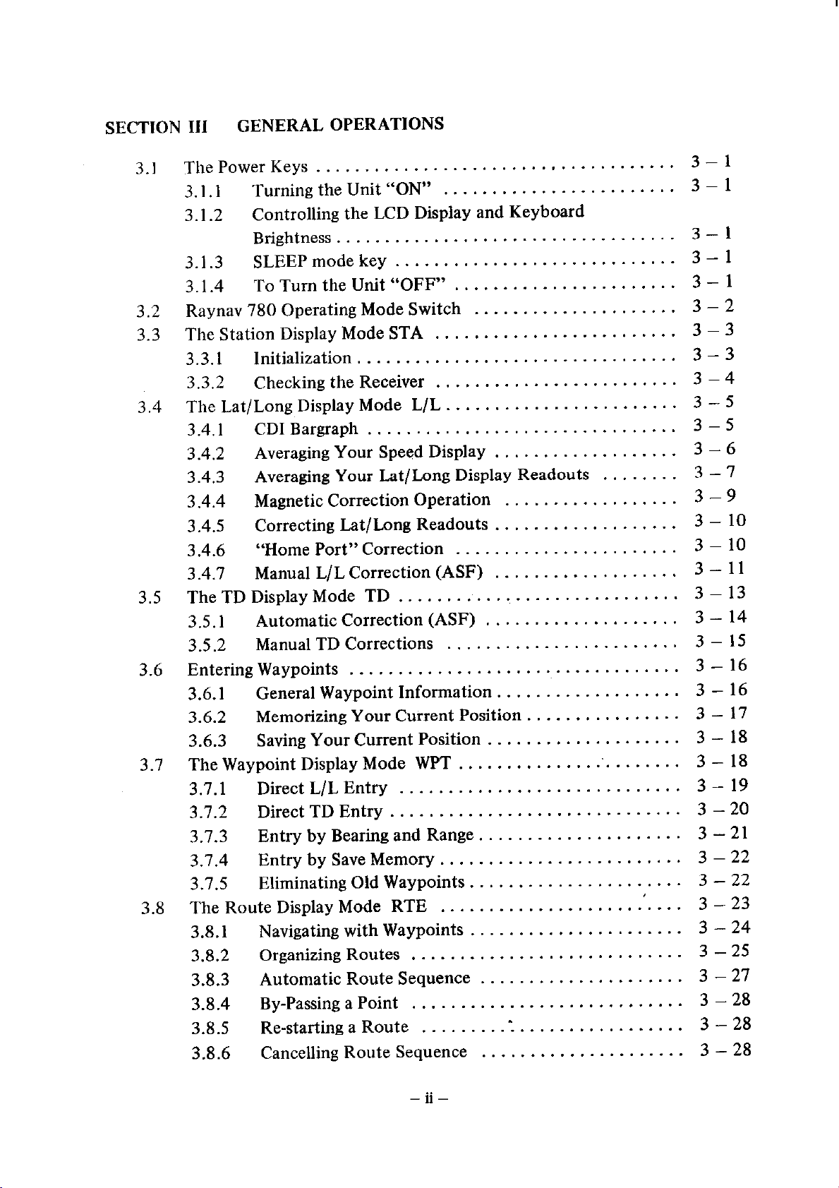
SECTION III
GENERAL OPERATIONS
3.1
3.2
3.3
3.4
3.5
3.6
3.1
3.8
The Power Keys
3.1.1
3.1.2
Turning the Unit “ON”
Controlling the LCD Display and Keyboard
Brightness.
3.1.3
3.1.4
SLEEP mode key
ToTumtheUnit“OFF”.
.....................................
..................................
.............................
Raynav 780 Operating Mode Switch
The Station Display Mode STA
3.3.1
3.3.2
Initialization.
Checking the Receiver
................................
.........................
.........................
The Lat/Long Display Mode L/L.
3.4.1
3.4.2
3.4.3
3.4.4
3.4.5
3.4.6
3.4.7
CD1 Bargraph
Averaging Your Speed Display
Averaging Your Lat/Long Display Readouts
Magnetic Correction Operation
Correcting Lat/Long Readouts
“Home Port” Correction
Manual L/L Correction (ASF)
TheTDDisplayMode TD
3.5.1
3.5.2
Automatic Correction (ASF)
Manual TD Corrections
Entering Waypoints
3.6.1
3.6.2
3.6.3
General Waypoint Information
Memorizing Your Current Position
Saving Your Current Position
................................
..............................
..................................
The Waypoint Display Mode WPT
3.7.1
3.7.2
3.7.3
3.1.4
3.7.5
Direct L/L Entry
Direct TD Entry
EntrybyBearingandRange.. ...................
Entry by Save Memory.
Eliminating Old Waypoints.
The Route Display Mode RTE
3.8.1
3.8.2
3.8.3
3.8.4
3.8.5
3.8.6
Navigating with Waypoints
Organizing Routes
Automatic Route Sequence
By-Passing a Point
Re-starting a Route
Cancelling Route Sequence
............................. 3 - 19
.............................. 3 - 20
.......................... 3 - 23
............................ 3 - 25
............................
........
3 - 1
........................
3 - 1
3 - 1
3 - 1
......................
.....................
3-l
3 - 2
3 - 3
3 - 3
3 - 4
.......................
3 - 5
3 - 5
...................
........ 3 - 7
..................
................... 3 - 10
....................... 3 - 10
...................
3 - 6
3 - 9
3 - 11
3 - 13
.................... 3 - 14
........................
3 - 15
3 - 16
...................
................
....................
........................
3 - 16
3 - 17
3 - 18
3 - 18
3-21
........................ 3 - 22
.....................
......................
..................... 3 - 27
3 - 22
3 - 24
3 - 28
................. 3 - 28
.I
..................... 3 - 28
3.9 Setting the Alarms
3.9.1
3.9.2
3.9.3
3.9.4
The Arrival Alarm
TheAnchorWatchAlarm..
The dffCourse Alarm
TheBoundaryAlarm
3.10 The Time Functions
3.10.1 UTC..
3.10.2 LOCAL
3.10.3 ETA..
................................... 3 - 29
............................
.........................
.......... .
.................................. 3 - 34
.....................................
....................................
.....................................
3.10.4 Special Time Functions (STF)
3.10.5 Countdown
................................. 3 - 36
3.11 The Special Function Display Mode SF
3.11.1 SelectingDataOutput
......................... 3 -38
3.11.2 Selecting NM/KTS, SM/MPH, or KM/KPH
3.11.3 RegisteredGRI’s
3.11.4 MasterReset..
3.11.5 SoftwareLevel
3.12 Specialized Operations
3.12.1 TheNotchFilters..
3.12.2 SelectMode
3.13 Extended Range Operation
3.14 Cross Chain Operation (Option)
3.14.1 ToUseCrossChain
.............................
...............................
............................... 3 -40
................................ 3 - 4 1
...........................
................................. 3 -43
............................ 3 - 43
.........................
........................... 3 -45
3 - 29
.....................
3 -31
3 - 32
...............
3 -33
3-35
3-35
3-35
...................
................... 3 - 37
..........
3 - 36
3 - 39
3-39
3-40
3-41
3 - 45
SECTION IV
4.1
4.2
General ............................................
Replacing the Fuse
MAINTENANCE
4.3 Replacing the Lamps
4.4 Replacing the Battery.
4.5 TCXO Calibration
SECTION V
REPLACEMENT PARTS . . . . . . . . . . . . . . . . . . . . . . . . .
APPENDIX
A BASIC LORAN THEORY . . . . . . . . . . . . . . . . . . . . . . . . .
B LORAN C CHAIN COVERAGE DIAGRAMS . . . . . . . . . B - 1
. WAYPOINT LOG PAGES
. WARRANTY REGISTRATION CARD
...................................
................................. 4 - 1
................................
...................................
- 11, -
4 - 1
4 - 1
4 - 2
4 - 2
5 - 1
A - 1

SECTION I
GENERAL lNFORMATlON
1 .l INTRODUCTION
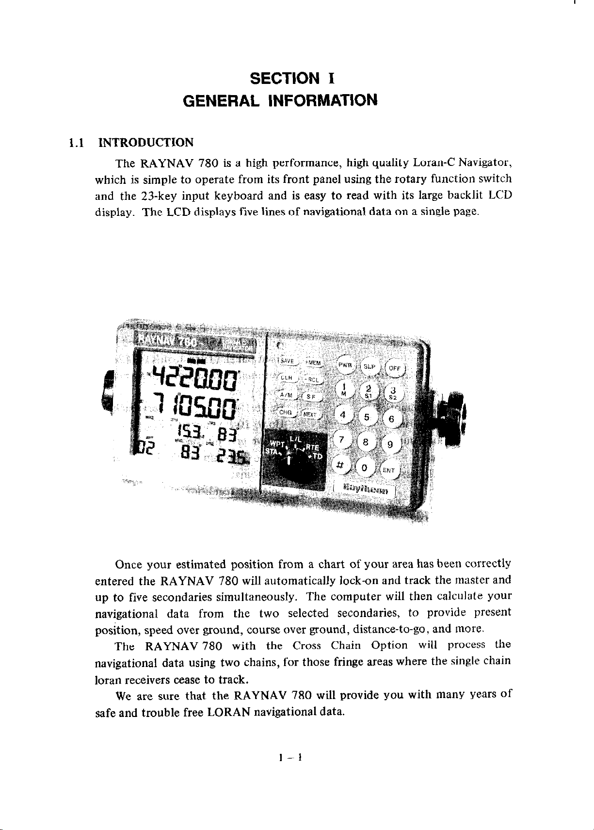
The RAYNAV 780 is a high performance, high quality Loran-C Navigator,
which is simple to operate from its front panel using the rotary function switch
and the 23-key input keyboard and is easy to read with its large backlit LCD
display.
The LCD displays five lines of navigational data on a single page.
Once your estimated position from a chart of your area has been corre,ctly
entered the RAYNAV 780 will automatically lock-on and track the master and
up to five secondaries simultaneously. The computer will then calculate your
navigational data from the two selected secondaries, to provide present
position, speed over ground, course over ground, distance-to-go, and more.
The RAYNAV 780 with the Cross Chain Option will process the
navigational data using two chains, for those fringe areas where the single chain
loran receivers cease to track.
We are sure that the RAYNAV 780 will provide you with many years of
safe and trouble free LORAN navigational data.
1.2 OPTIONAL EQUIPMENT
Console Mounting Kit
Rugged Duty Antenna Coupler
M56759
AW-757 (M95953)
Other options are listed in the installation section of this manual
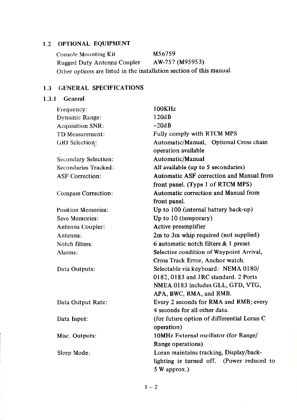
1.3 GENERAL SPECIFICATIONS
1.3.1 General
Frequency:
Dynamic Range:
Acquisition SNR:
TD Measurement:
GRI Selection:
1 OOKHz
120dB
-2OdB
Fully comply with RTCM MPS
Automatic/Manual, Optional Cross chain
operation available
Secondary Selection:
Secondaries Tracked:
ASF Correction:
Automatic/Manual
All available (up to 5 secondaries)
Automatic ASF correction and Manual from
front panel. (Type 1 of RTCM MPS)
Compass Correction:
Automatic correction and Manual from
Position Memories:
Save Memories:
Antenna Coupler:
Antenna:
Notch filters:
Alarms:
Data Outputs:
Data Output Rate:
Data Input:
Misc. Outputs:
Sleep Mode:
front panel.
Up to 100 (internal battery back-up)
Up to 10 (temporary)
Active preamplifier
2m to 3m whip required (not supplied)
6 automatic notch filters & 1 preset
Selective condition of Waypoint Arrival,
Cross Track Error, Anchor watch.
Selectable via keyboard: NEMA 01 SO/
0182,0183 and JRC standard. 2 Ports
NMEA 0183 includes GLL, GTD, VTG,
APA, BWC, RMA, and RMB.
Every 2 seconds for RMA and RMB; every
4 seconds for all other data.
(for future option of differential Loran C
operation)
1 OMHz External oscillator (for Range/
Range operations)
Loran maintains tracking, Display/backlighting is turned off. (Power reduced to
5 W approx.)
l-2
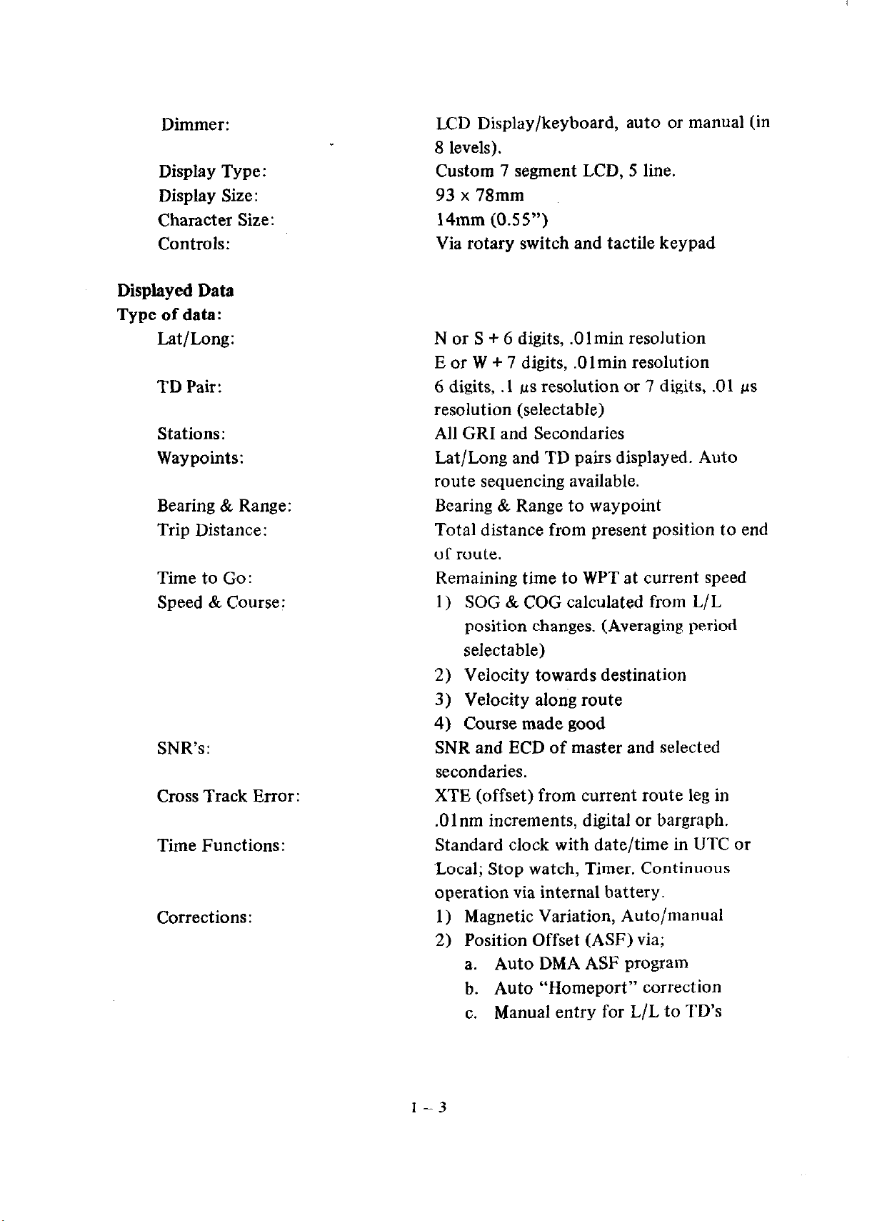
Dimmer:
LCD Display/keyboard, auto or manual (in
8 levels).
Display Type:
Display Size:
Character Size:
Controls:
Displayed Data
Type of data:
Lat/Long:
TD Pair:
Stations:
Waypoints:
Bearing & Range:
Trip Distance:
Time to Go:
Speed & Course :
Custom 7 segment LCD, 5 line.
93 x 78mm
14mm (0.55”)
Via rotary switch and tactile keypad
N or S + 6 digits, .O 1 min resolution
E or W + 7 digits, .Olmin resolution
6 digits, .l ns resolution or 7 digits, .Ol ps
resolution (selectable)
All GRI and Secondaries
Lat/Long and TD pairs displayed. Auto
route sequencing available.
Bearing & Range to waypoint
Total distance from present position to end
of route.
Remaining time to WPT at current speed
1) SOG & COG calculated from L/L
position changes. (Averaging period
selectable)
SNR’s:
Cross Track Error:
Time Functions:
Corrections:
2) Velocity towards destination
3) Velocity along route
4) Course made good
SNR and ECD of master and selected
secondaries.
XTE (offset) from current route leg in
.Olnm increments, digital or bargraph.
Standard clock with date/time in UTC or
‘Local; Stop watch, Timer. Continuous
operation via internal battery.
1) Magnetic Variation, Auto/manual
2) Position Offset (ASF) via;
a. Auto DMA ASF program
b. Auto “Homeport” correction
c. Manual entry for L/L to TD’s
1-3
Warning Indicators:
Low SNR, Blink, Cycle selection, no L/L
solution. On-screen and audible alert for
Arrival, XTE, or Anchor watch alarms.
Co-ordinate Conversion:
Interference:
Power:
Memory Protection:
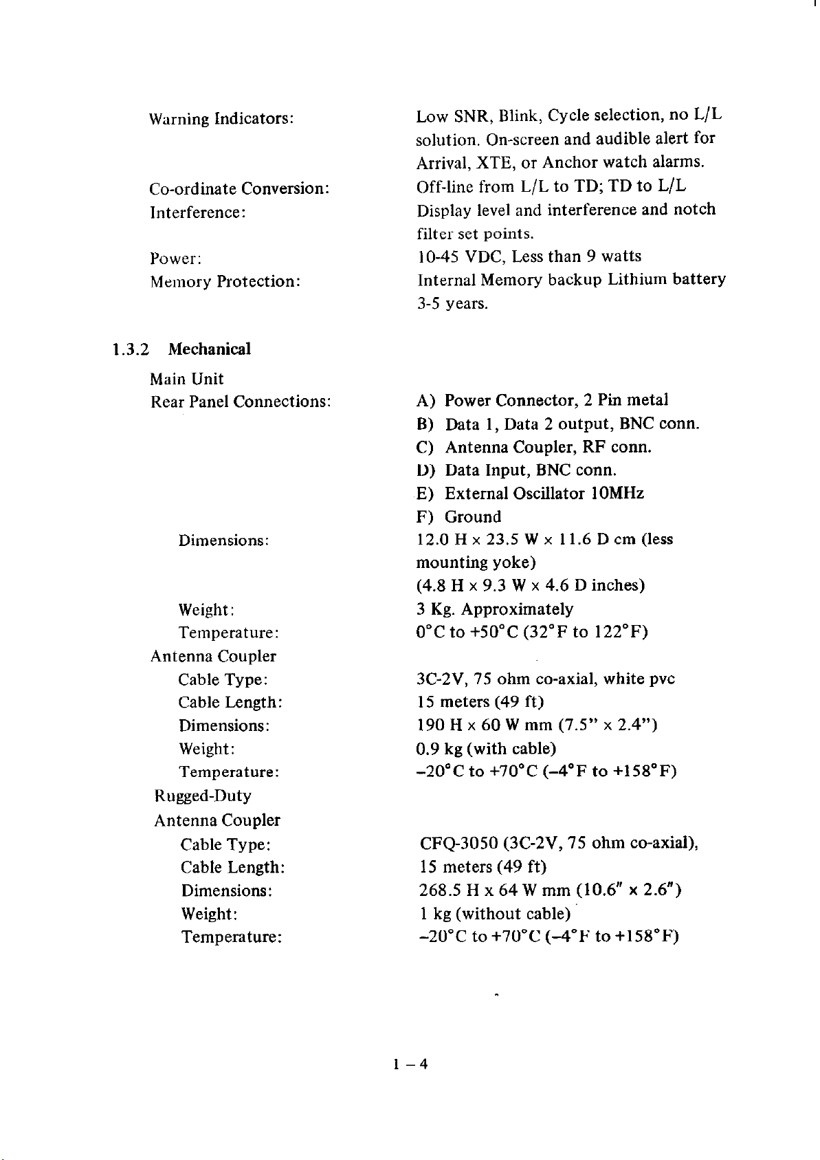
1.3.2 Mechanical
Main Unit
Rear Panel Connections:
Dimensions:
Off-line from L/L to TD; TD to L/L
Display level and interference and notch
filter set points.
lo-45 VDC, Less than 9 watts
Internal Memory backup Lithium battery
3-5 years.
Power Connector, 2 Pin metal
A)
Data 1, Data 2 output, BNC corm.
B)
Antenna Coupler, RF corm.
C)
Data Input, BNC corm.
D)
External Oscillator 1OMHz
E)
Ground
F)
12.0 H x 23.5 W x 11.6 D cm (less
mounting yoke)
(4.8 H x 9.3 W x 4.6 D inches)
Weight:
Temperature:
Antenna Coupler
Cable Type:
Cable Length:
Dimensions:
Weight :
Temperature:
Rugged-Duty
Antenna Coupler
Cable Type:
Cable Length:
Dimensions:
Weight :
Temperature:
3 Kg. Approximately
0°C to +5O”C (32°F to 122°F)
3C-2V, 75 ohm co-axial, white pvc
15 meters (49 ft)
190 H x 60 W mm (7.5” x 2.4”)
0.9 kg (with cable)
-20°C to +7O”C (-4°F to +158”F)
CFQ-3050 (3C-2V, 75 ohm co-axial),
15 meters (49 ft)
268.5 H x 64 W mm (10.6” x 2.6”)
1 kg (without cable)
-20°C to +7O”C (-4°F to +158”F)
l-4
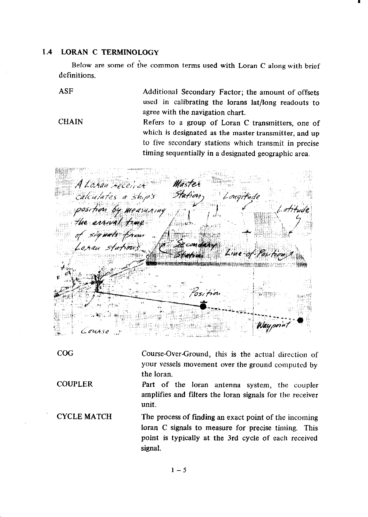
1.4 LORAN C TERMINOLOGY
Below are some of ihe common terms used with Loran C along with brief
definitions.
ASF
CHAIN
Additional Secondary Factor; the amount of offsets
used in calibrating the lorans lat/long readouts to
agree with the navigation chart.
Refers to a group of Loran C transmitters, one of
which is designated as the master transmitter, and up
to five secondary stations which transmit in precise
timing sequentially in a designated geographic area.
COG
COUPLER
CYCLE MATCH
Course-OverCround, this is the actual direction of
your vessels movement over the ground computed by
the loran.
Part of the loran antenna system, the coupler
amplifies and filters the loran signals for the receiver
unit.
The process of finding an exact point of the incoming
loran C signals to measure for precise timing. This
point is typically at the 3rd cycle of each received
signal.
l-5
ECD
GRI
LATITUDE
Envelope-to Cycle Difference, this is a technical
measurement of the shape of the incoming signals to
determine the probability of a correct cycle match.
Group-Repetition-Interval, this refers to the assigned
precise timing interval in which the loran chain must
perform its sequential transmissions. Measured in
microseconds, the GRI timing is used to identify the
loran chains worldwide. (99,600ns = 9960 GRI)
Angular measure in degrees North (0 - 90”) and
South (0 - 90”) from the Equator. On a chart these
lines are drawn from right to left.
LONGITUDE
LOP
MASTER
MICROSECOND
SECONDARY
SNR
SOG
Angular measure in degrees (0 - 180”) East and West
of the prime meridian (0”) at Greenwich, England.
On a chart these lines are drawn from top to bottom.
Line-Of Position, refers to a line made up of points
where the time measured between the receipt of the
master signal and a secondary station is always the
same. Loran LOP’s are frequently printed on the
marine charts and are otherwise known as Time
Difference Lines or TD’s.
In a loran chain, the Master station initiates the trans-
mitting sequence.
In loran C, the basic unit of time measurement of the
loran signals.
Any station in a loran chain other than the Master.
Signal-to-Noise Ratio, the measurement of the
received signal’s strength related to the background
noise comming into the loran receiver.
Speed-Over-Ground, this is the calculated rate of
movement of the vessel over the ground.
TD
VARIATION
WAYPOINT
XTE
Time Difference, refers to the elapsed time in microseconds between the arrival of the master and a
secondary signal in a loran receiver.
In loran, refers to the difference in degrees between
“True North” and “Magnetic North.”
Geographical destination defined in the loran
memories as a Latitude/Longitude position.
Cross-Track-Error, this is the calculated deviation
from a track line drawn from the origination point to
the destination waypoint retained in the loran’s
memory.
SECTION II
-INSTALLATION
Although your Raynav 780 is designed to the highest levels of quality and
performance, it can best attain those standards when a proper installation of the
equipment has been achieved.
This section provides the user with practical guidelines to assist in the planning
and installation of the Raynav 780 aboard your vessel.
2.1 UNPACKING AND INSPECTION
Do use care when unpacking the unit from shipping carton to prevent
damage to the contents. It is also good practice to save the carton and the
interior packing material until the unit has been statisfactorily installed on the
vessel. The original packing material should be used in the unlikely event
that it is necessary to return the unit to the factory.
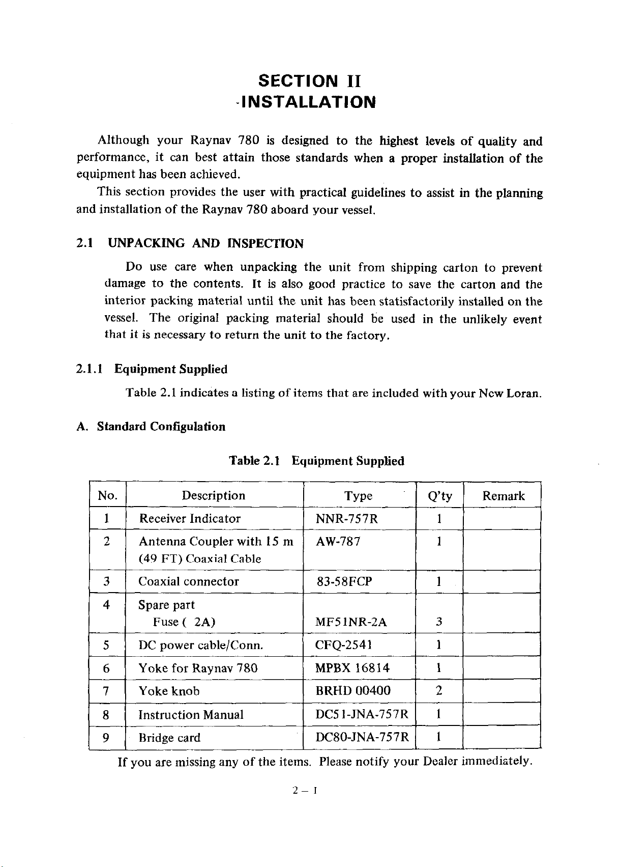
2.1.1 Equipment Supplied
Table 2.1 indicates a listing of items that are included with your New Loran.
A. Standard Conilgulation
No. Description
1 Receiver Indicator
2 Antenna Coupler with
(49 FT) Coaxial Cable
3 Coaxial connector
4 Spare part
Fuse ( 2A)
5 DC cable/Corm.
6 Yoke for Raynav 780
power
Table 2.1 Equipment Supplied
Type Q’ty
NNR-757R
1.5 m AW-787
83-58FCP
MF5 lNR-2A
CFQ-2541
MPBX 16814 1
Remark
1
1
1
3
1
1
I7 I
8
9
Yoke knob
Instruction Manual
Bridge card
If you are missing any of the items. Please notify your Dealer immediately.
( BRHD 00400
DC5 I-JNA-757R 1
DC80-JNA-757R 1
I 2 I
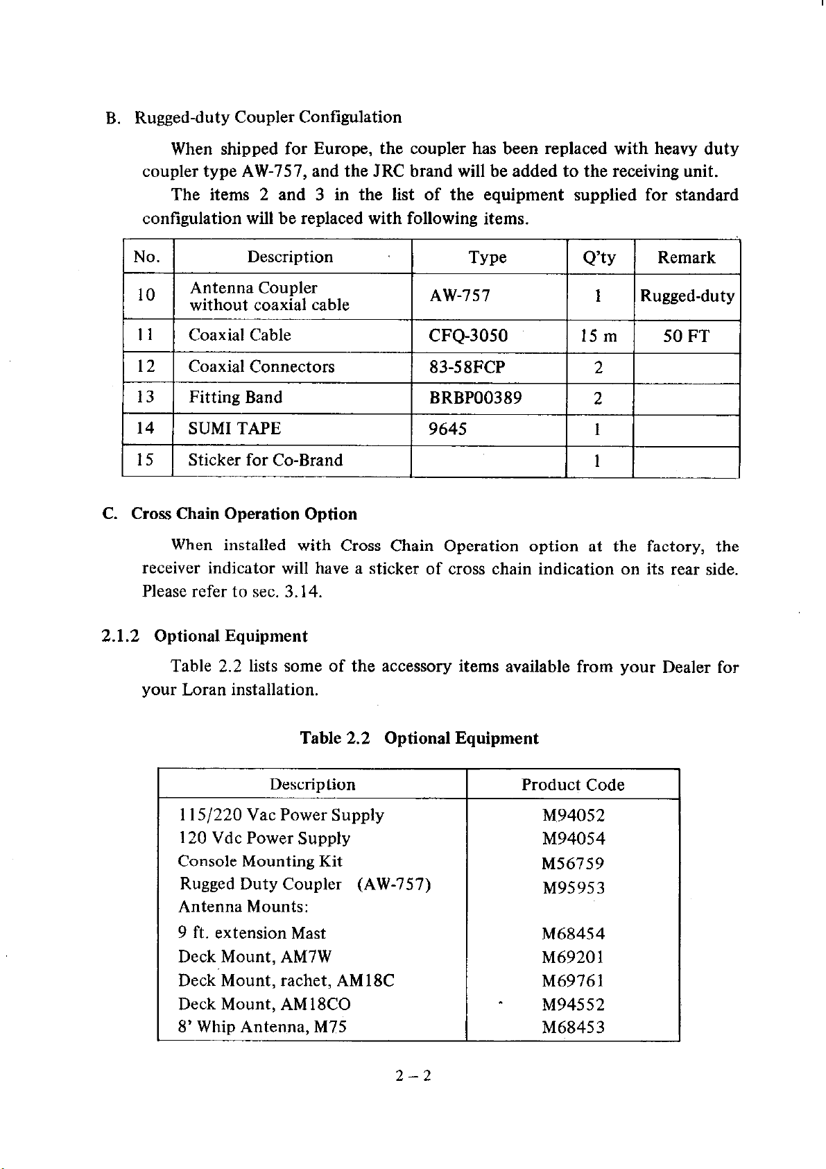
B. Rugged-duty Coupler Contigulation
When shipped for Europe, the coupler has been replaced with heavy duty
coupler type AW-757, and the JRC brand will be added to the receiving unit.
The items 2 and 3 in the list of the equipment supplied for standard
contigulation will be replaced with following items.
No.
Antenna Coupler
without coaxial cable
Coaxial Cable
12
13
14
15
C. Cross Chain Operation Option
receiver indicator will have a sticker of cross chain indication on its rear side.
Please refer to sec. 3.14.
2.1.2 Optional Equipment
Coaxial Connectors
Fitting Band
SUM1 TAPE
Sticker for Co-Brand
When installed with Cross Chain Operation option at the factory, the
Description
Type I Q’ty I
AW-757
CFQ-3050
83-58FCP
BRBP00389
9645
1 Rugged-duty
15m
2
2
1
1
Remark
50 FT
Table 2.2 lists some of the accessory items available from your Dealer for
your Loran installation.
Table 2.2 Optional Equipment
Description Product Code
1151220 Vat Power Supply
120 Vdc Power Supply
Console Mounting Kit
Rugged Duty Coupler (AW-757)
Antenna Mounts:
9 ft. extension Mast
Deck Mount, AM7W
Deck Mount, rachet, AMl8C
Deck Mount, AMl8CO
8’ Whip Antenna, M75
I
M94052
M94054
M56759
M95953
M68454
M6920 1
M69761
M94552
M68453
2-2
2.2 RECEIVER INSTALLATION
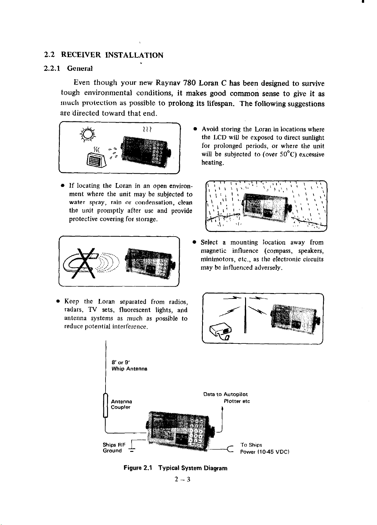
2.2.1 General
Even though your new Raynav 780 Loran C has been designed to survive
tough environmental conditions, it makes good common sense to give it as
much protection as possible to prolong its lifespan. The following suggestions
are ilirected toward that end.
r P%
L
l If locating the Loran in an open environ-
ment where the unit may be subjected to
water spray, rain or condensation, clean
the unit promptly after use and provide
protective covering for storage.
211
1
J
1
l Keep the Loran separated from radios.
radars, TV sets, fluorescent
antenna systems as much as
reduce potential interference.
lights, and
possible to
l Avoid storing the Loran in locations where
the LCD will be exposed to direct sunlight
for prolonged periods, or where the unit
will be subjected to (over 50°C) excessive
heating.
.
Select a mounting location away from
magnetic influence (compass, speakers,
minimotors, etc., as the electronic circuits
may be influenced adversely.
8’ or 9’
WhiQ Antenna
AllfSlllla
Coupler
n
Figure 2.1 Typical System Diagram
Data to Autopilot
Plotter etc
t
2-3
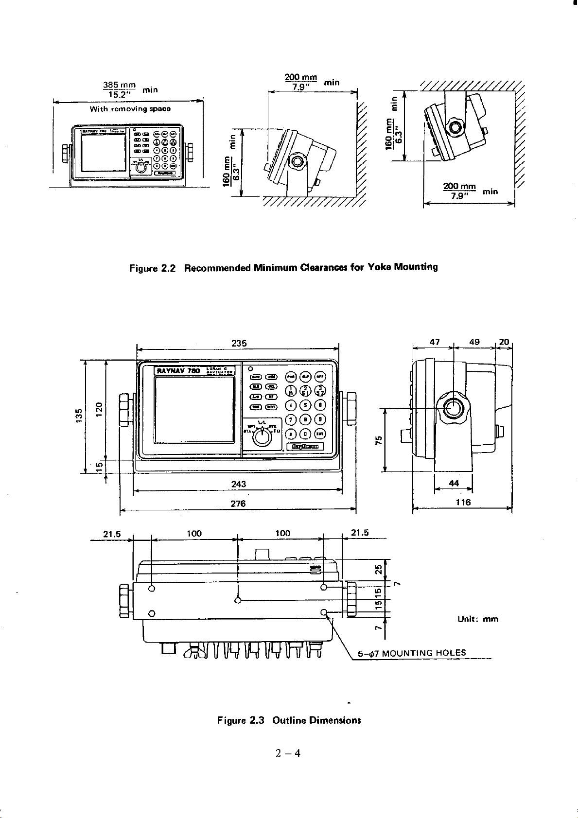
2OOmm
385 mi”
15.2”
Figure 2.2 Recommended Minimum Clearances for Yoke Mounting
235
243
276
=I
Figure 2.3 Outline Dimensions
2-4
Unit: mm
5-,$7 MOUNTING HOLES
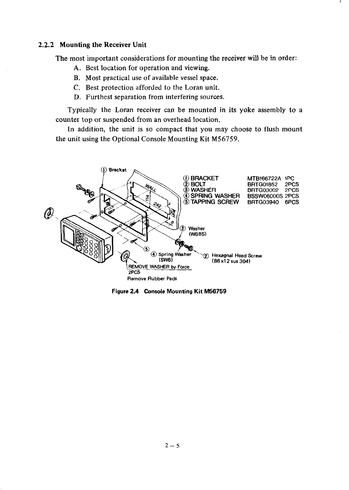
2.2.2 Mounting the Receiver Unit
The most important considerations for mounting the receiver will be in order:
A. Best location for operation and viewing.
B. Most practical use of available vessel space.
C. Best protection afforded to the Loran unit.
D. Furthest separation from interfering sources.
Typically the Loran receiver can be mounted in its yoke assembly to a
counter top or suspended from an overhead location.
In addition, the unit is so compact that you may choose to flush mount
the unit using the Optional Console Mounting Kit M56759.
MTB166722A 1PC
BRTG01652 2PCS
BRTG03002 2PCS
@SPRING WASHER BSSWOGOOOS ZPCS
@TAPPING SCREW BRTG03940 6PCS
q!E WASHER by Force
ZPCS
Remove Flubber Pads
Figure 2.4
Console Mounting Kit M56759
2-5
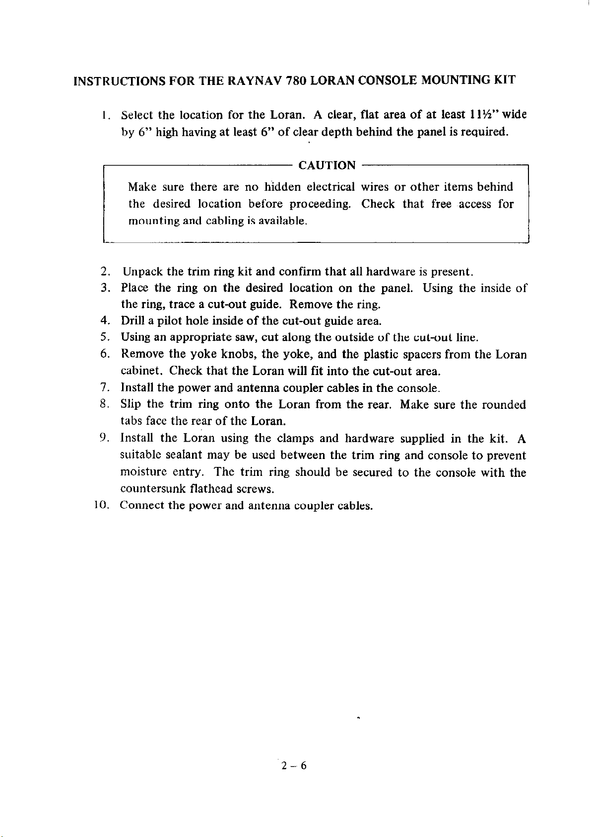
INSTRUCTIONS FOR THE RAYNAV 780 LORAN CONSOLE MOUNTING KIT
I. Select the location for the Loran. A clear, flat area of at least 11%” wide
by 6” high having at least 6” of clear depth behind the panel is required.
y CAUTION
Make sure there are no hidden electrical
the desired location before proceeding.
mounting and cabling is available.
Unpack the trim ring kit and confirm that all hardware is present.
2,
Place the ring on the desired location on the panel. Using the inside of
3.
the ring, trace a cut-out guide. Remove the ring.
4.
Drill a pilot hole inside of the cut-out guide area.
5.
Using an appropriate saw, cut along the outside of the cut-out line.
6.
Remove the yoke knobs, the yoke, and the plastic spacers from the Loran
cabinet. Check that the Loran will fit into the cut-out area.
I.
Install the power and antenna coupler cables in the console.
8.
Slip the trim ring onto the Loran from the rear. Make sure the rounded
tabs face the rear of the Loran.
9.
Install the Loran using the clamps and hardware supplied in the kit. A
suitable sealant may be used between the trim ring and console to prevent
moisture entry. The trim ring should be secured to the console with the
countersunk flathead screws.
10.
Connect the power and antenna coupler cables.
2-6
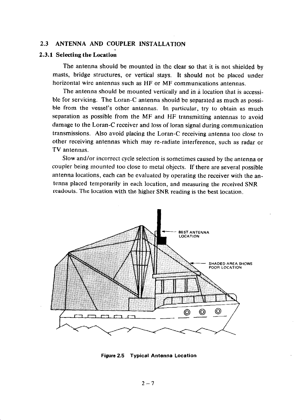
2.3 ANTENNA AND COUPLER INSTALLATION
2.3.1 Selecting the Location
The antenna should be mounted in the clear so that it is not shielded by
masts, bridge structures, or vertical stays. It should not be placed under
horizontal wire antennas such as HF or MF communications antennas.
The antenna should be mounted vertically and in a location that is accessi-
ble for servicing. The Loran-C antenna should be separated as much as possible from the vessel’s other antennas. In particular, try to obtain as much
separation as possible from the MF and HF transmitting antennas to avoid
damage to the Loran-C receiver and loss of loran signal during communication
transmissions. Also avoid placing the Loran-C receiving antenna too close to
other receiving antennas which may re-radiate interference, such as radar or
TV antennas.
Slow and/or incorrect cycle selection is sometimes caused by the antenna or
coupler being mounted too close to metal objects. If there are several possible
antenna locations, each can be evaluated by operating the receiver with the an-
tenna placed temporarily in each location, and measuring the received SNR
readouts. The location with the higher SNR reading is the best location.
Figure 2.5 Typical Antenna Location
2-7
2.3.2 Antenna Whip
This unit is designed for use with an ordinary 8 or 9 ft. fiberglass whip.
The whip screws directly into the antenna coupler. We do not recommend the
use of combination VHF/Loran antennas with this product. The use of combination antennas with the RAYNAV 780 can result in poor or unreliable
Loran performance.
2.3.3 Antenna Coupler
The standard antenna coupler is shipped with 49 feet of cable already
connected at the coupler end. A Solderless RF Coaxial connector is supplied
for the other end, to be attached after the cable is routed through the vessel
and up to the back of the RAYNAV 780. The cable can be cut to an appropriate length or extended as necessary with additional coax (up to 200Ft).
2.3.4 Mounting the Coupler
The coupler may be mounted on a hollow core extension mast or directly
to a swivel mount with l”-14 standard marine threads.
Assemble the whip antenna, coupler, extension mast and mounting hardware. The mast may be mounted to the vessel using any standard marine
mounting fixtures. The cable from the coupler is run through the extension
mast and out near the bottom of the mast above the ferrule.
2-a
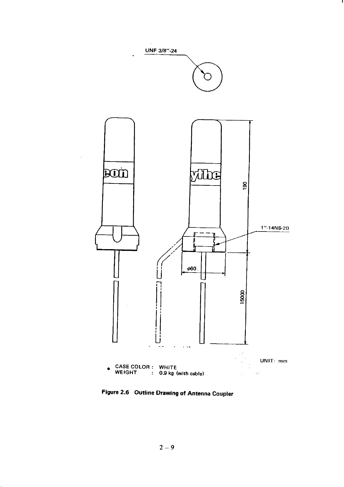
UNF 3/W-24
\
. CASECOLOR: WHITE
WEIGHT
Figure 2.6
Outline Drawing of Antenna Coupler
: 0.9 kg (with cable)
1”-14NS.ZB
UNIT: m,,,
2-9
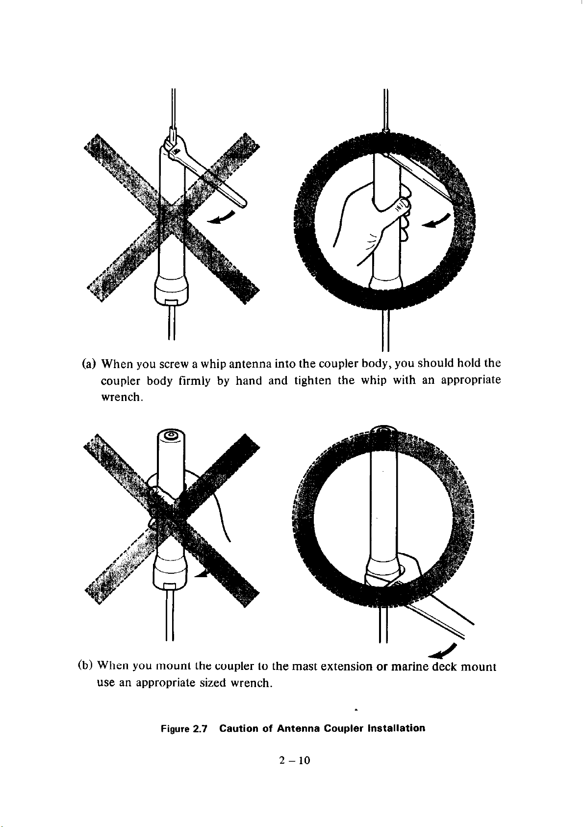
(a) When you screw a whip antenna into the coupler body, you should hold the
coupler body firmly by hand and tighten the whip with an appropriate
wrench.
(b) When you mount the coupler to the mast extension or marine deck mount
use an appropriate sized wrench.
Figure 2.7 Caution of Antenna Coupler InStallatiOn
2 - 10
SHORT WIRE 24 in. MA
ANTENNA WHIP
8FTw9FT
BOLT
- WAWER
- LUG
- WAWER
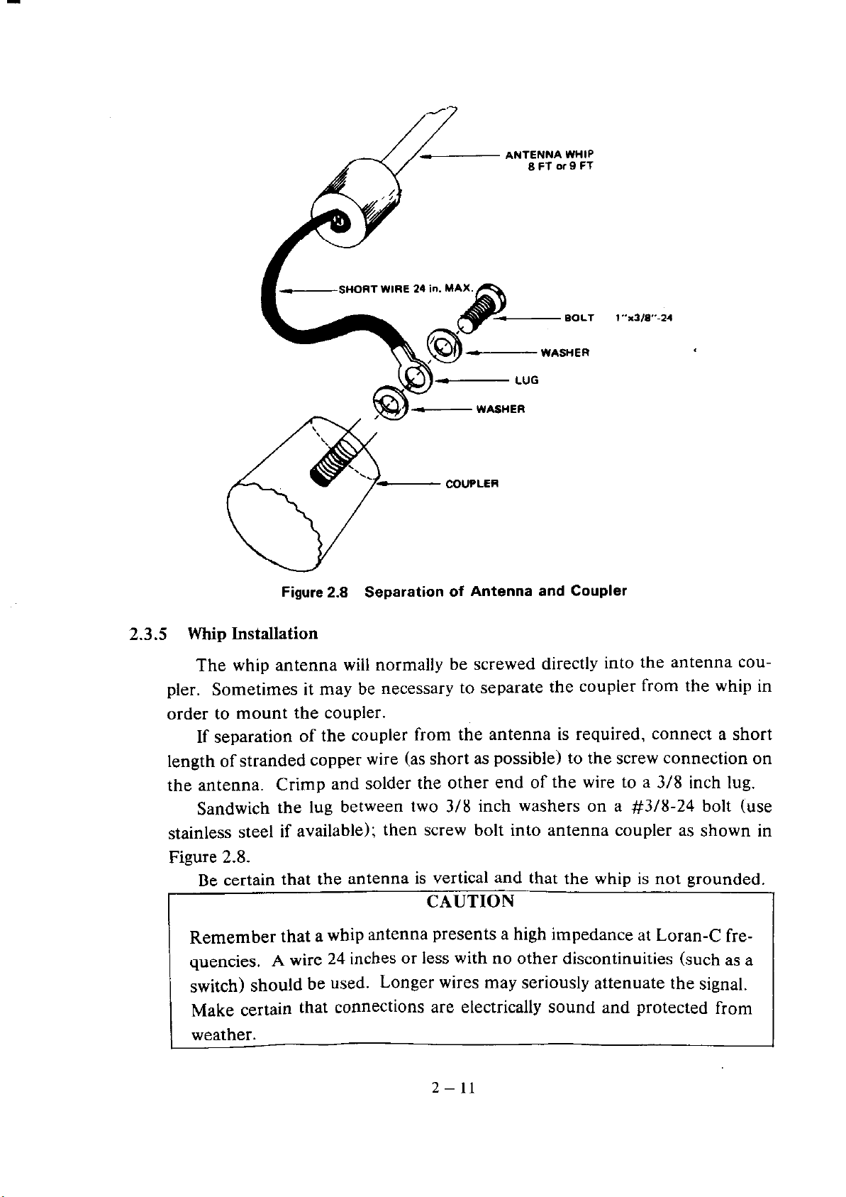
Figure 2.8 Separation of Antenna and Coupler
l”rwr.24
2.3.5 Whip Installation
The whip antenna will normally be screwed directly into the antenna COW
pler. Sometimes it may be necessary to separate the coupler from the whip in
order to mount the coupler.
If separation of the coupler from the antenna is required, connect a short
length of stranded copper wire (as short as possible) to the screw connection on
the antenna. Crimp and solder the other end of the wire to a 3/8 inch lug.
Sandwich the lug between two 3/8 inch washers on a #3/8-24 bolt (use
stainless steel if available); then screw bolt into antenna coupler as shown in
Figure 2.8.
Be certain that
the antenna is vertical and that the whip is not grounded.
CAUTION
Remember that a whip antenna presents a high impedance at Loran-C fre-
quencies. A wire 24 inches or less with no other discontinuities (such as a
switch) should be used. Longer wires may seriously attenuate the signal.
Make certain that connections are electrically sound and protected from
weather.
2- 11
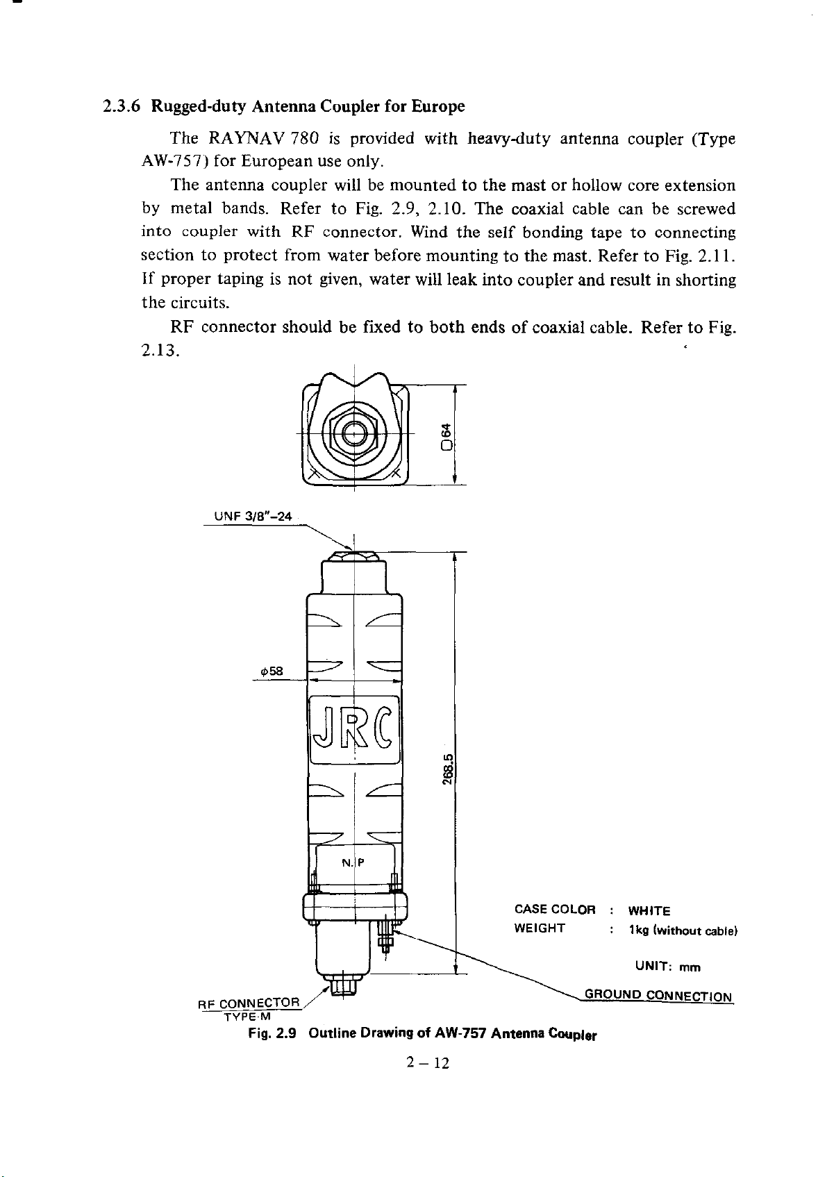
2.3.6 Rugged-duty Antenna Coupler for Europe
The RAYNAV 780 is provided with heavy-duty antenna coupler (Type
AW-157) for European use only.
The antenna coupler will be mounted to the mast or hollow core extension
by metal bands. Refer to Fig. 2.9, 2.10. The coaxial cable can be screwed
into coupler with RF connector. Wind the self bonding tape to connecting
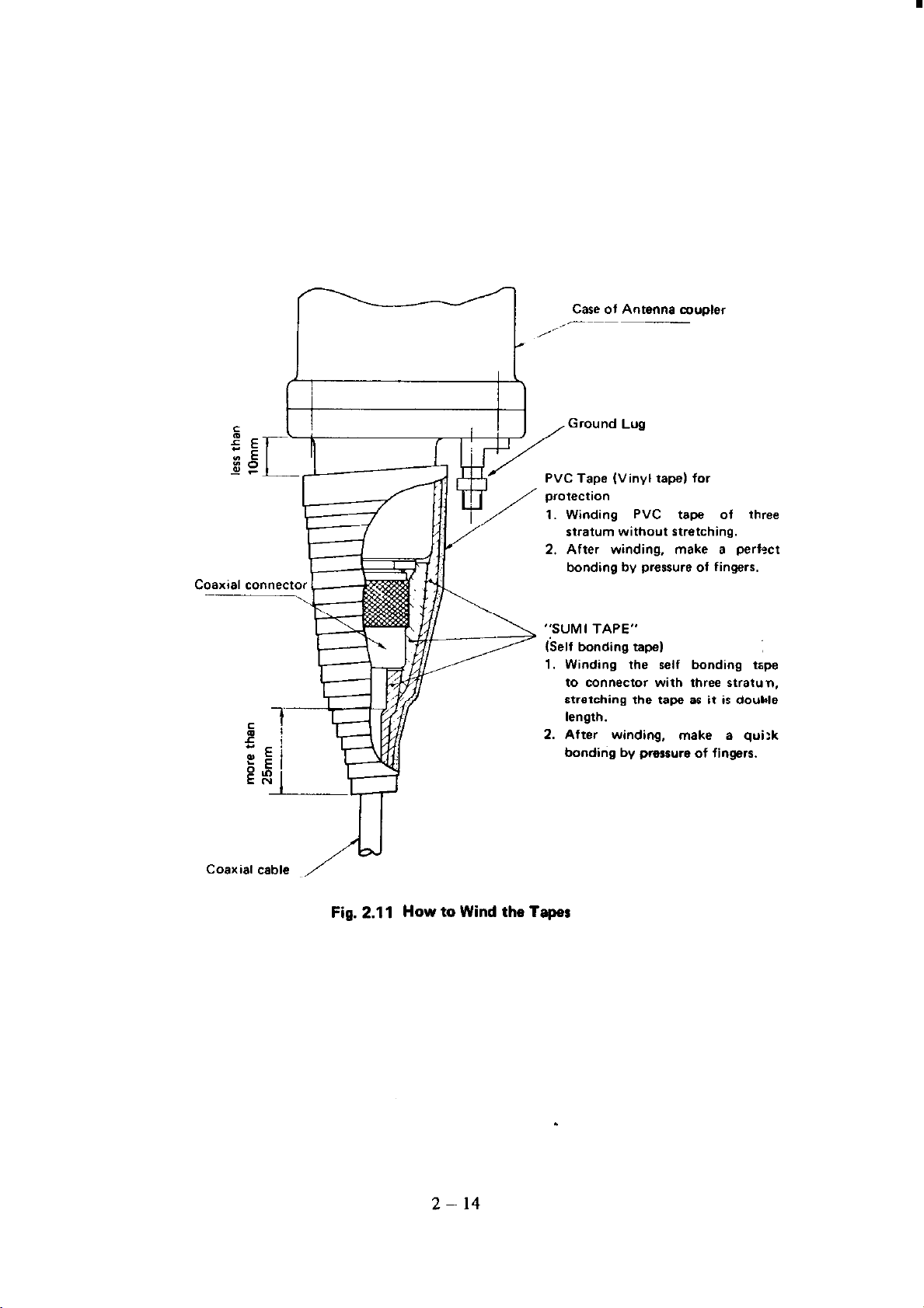
section to protect from water before mounting to the mast. Refer to Fig. 2.11.
If proper taping is not given, water will leak into coupler and result in shorting
the circuits.
RF connector should be fixed to both ends of coaxial cable. Refer to Fig.
2.13.
UNF 3/8”-24
-+=i---
CASECOLOR : WHITE
WEIGHT
: 1 kg (without cable1
RF CONNECTOR
TYPE-M
Fig. 2.9 Outline Drawing of AW-757 Antenna Coupler
UNIT: mm
GROUND CONNECTION
2- 12
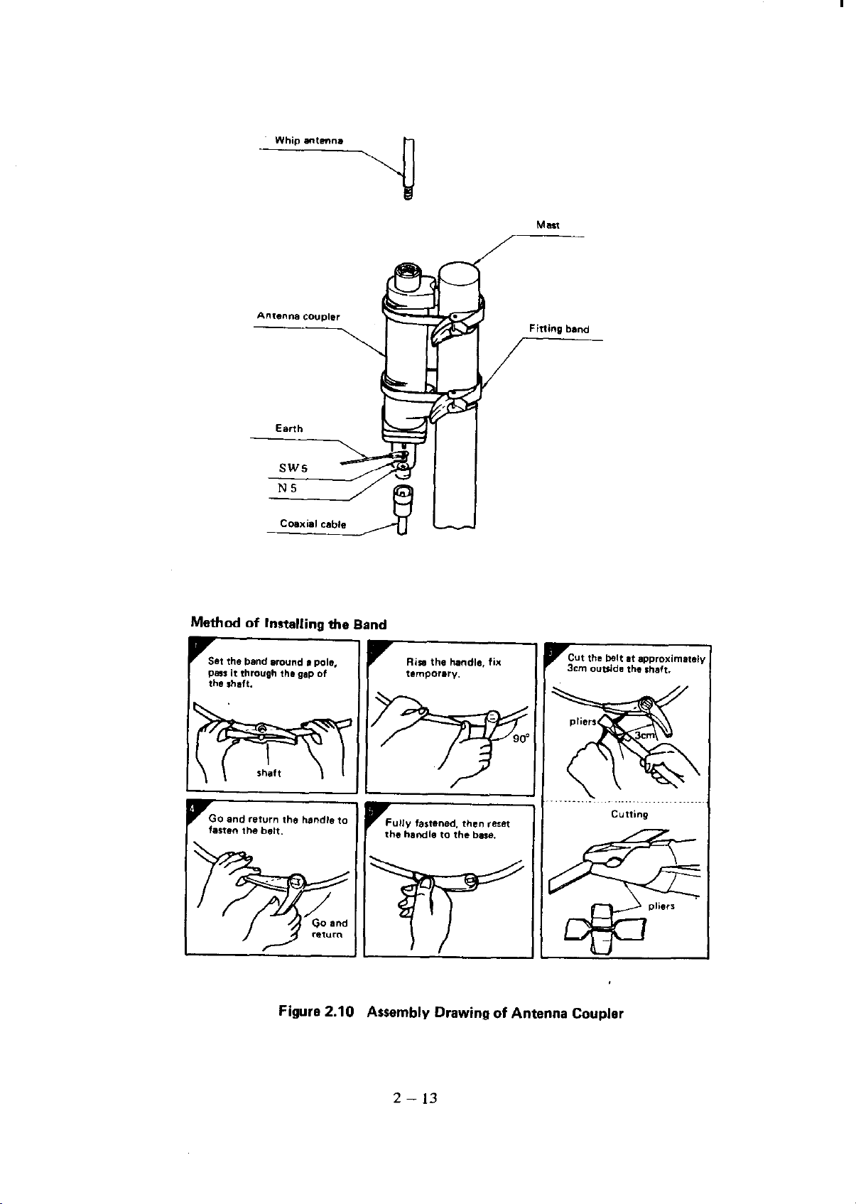
Method of Installing the Band
Figure 2.10 Assembly Drawing of Antenna Coupler
2 - 13
/Ikl Coaxial cable
Fig. 2.11 How to Wind the Taper
ape (Vinyl tape1 for
1. Winding PVC tape of three
stratum without stretching.
2. After winding, make a perfxt
bonding by pressure of fingers.
“SUMI TAPE”
Winding the self bonding tape
to connector with three stratun.
stretching the tape as it is double
length.
After winding, make a qui:k
bonding by pressure of fingers.
2- 14
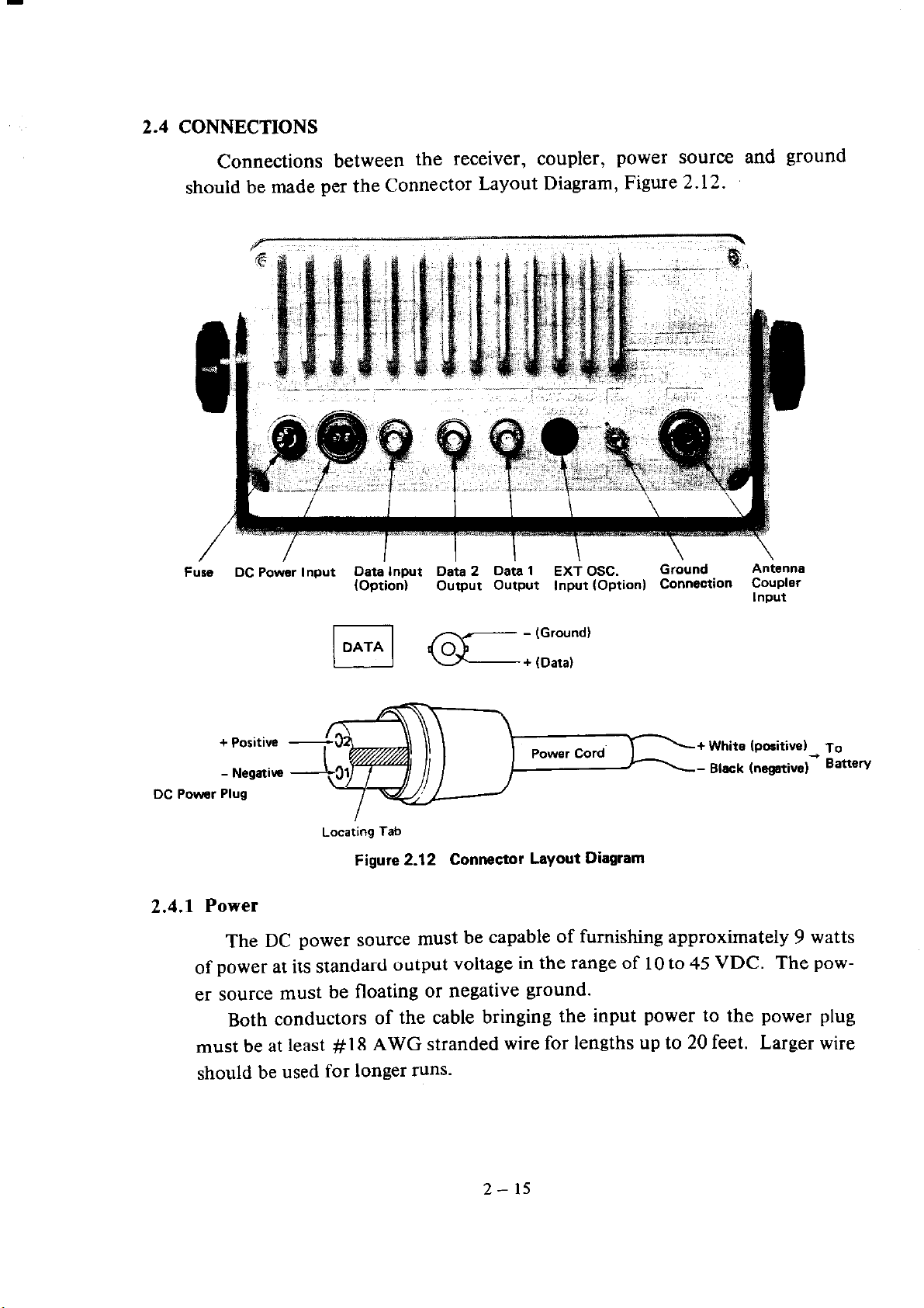
2.4 CONNECTIONS
Connections between the receiver, coupler, power source and ground
should be made per the Connector Layout Diagram, Figure 2.12.
I
FUW
DC Power Plug
DC Power Input Data Input Data 2 Data 1
(Option) Output Output Input (Option) Connection Coupler
EX+ OSC.
Locating Tab
Figure 2.12 Connector Layout Diagram
Grdund
+ White (positi
- Black Inegative)* Banew
A&ma
Input
2.4.1 Power
The DC power source must be capable of furnishing approximately 9 watts
of power at its standard output voltage in the range of 10 to 45 VDC. The power source must be floating or negative ground.
Both conductors of the cable bringing the input power to the power plug
To
must be at least #18 AWG stranded wire for lengths up to 20 feet. Larger wire
should be used for longer runs.
2- 15
 Loading...