

Page 1

RAYDATA Installation and Operation Handbook
RayData
Installation and Operation Handbook
IMPORTANT NOTICE
This device is only an aid to navigation. Its accuracy can be
affected by many factors, including equipment failure or defects,
environmental conditions and improper handling or use.
It is the user’s responsibility to exercise common prudence and
navigational judgement, and this device should not be relied upon
as a substitute for such prudence and judgement.
Page 2

Installation and Operation Han
dbook
RAYMARINE products are supported by a network of Authorized
Service Representatives. For information on Raymarine products and
services, contact either of the following:
UNITED STATES
Raymarine Incorporated
22 Cotton Road
Unit H
Nashua
New Hampshire 03063-4219
Telephone: +1 603 881 5200
Fax: +1 603 864 4756
EUROPE
Raymarine Limited
Anchorage Park
Portsmouth
Hampshire PO3 5TD
England
Telephone: +44 (0) 2392 693611
Fax: +44 (0) 2392 694624
Copyright © Raymarine 2001
To the best of our knowledge, the technical and graphical information
contained in this handbook was correct when it went to press. However,
the Raymarine policy of continuous improvement and updating may
change product specifications without prior notice. Therefore,
unavoidable differences may occur, between the product and the
handbook, from time to time, for which liability cannot be accepted by
Raymarine.
SeaTalk and RayData are trademarks of Raymarine.
Page 3

61
Page 4

Preface i
Preface
Congratulations on the purchase of your RayData™ multi-function
instrument from Raymarine.
This handbook contains very important information on the installation
and operation of your new equipment. In order to get the best results in
operation and performance, please read this handbook thoroughly.
How this Handbook is Organised
This handbook is divided into the following chapters:
Chapter 1: Introduces the RayData, its features and its use, either
stand-alone or as part of a larger system.
Chapter 2: Provides instructions for installing the RayData.
Chapter 3: Explains how to start using the RayData, including
instructions for turning it on, interpreting and changing the data displays,
changing the lighting, and sending/receiving a man overboard warning.
Chapter 4: Provides instructions for setting up the RayData defaults,
such as the numerical units used, to suit your prefences. It also explains
how to calibrate your speed transducer to obtain an accurate speed
display.
Chapter 5: Explains how to set up alarm threshold values, and how to
deal with alarm conditions.
Chapter 6: Provides detailed reference information on each of the
display pages, including depth, temperature, speed, log and navigation
displays.
Chapter 7: Provides information to help you to resolve any problems
you may encounter when using your RayData.
Appendix A: Provides details of the functions of all the RayData key
presses.
Appendix B: Lists the data sources that may be used by the RayData,
and their priorities.
Appendix C: Lists the system specifications.
A glossary, index and the warranty registration card are included at the
end of the handbook, and a mounting template is attached just inside
the rear cover.
Page 5

ii RAYDATA Installation and Operation Handbook
Recommended Use
When you first receive your RayData, you should read Chapters 1 and 2,
and install the equipment. Then read Chapter 3, and familiarise yourself
with the basic operation of the RayData. You may wish to refer to the
RayData Quick Reference Card and to Chapter 6 for more details about
some displays.
When you are happy using the RayData, read Chapters 4 and 5, decide
how you wish to set up your defaults and alarms, and follow the
instructions in those chapters to make your changes. Chapter 4 also
explains how to calibrate the speed so that you obtain an accurate
reading for your vessel.
If you experience any difficulties with your RayData, refer to Chapter 7.
Conventions
Throughout this handbook, the keys are shown in bold capitals: for
example, SPEED.
W arranty
Terms in bold type are included in the glossary.
To verify your RayData ownership, please take a few minutes to fill out
the warranty registration card found at the end of this handbook. It is
very important that you complete the owner information and return the
card to the factory in order to receive full warranty benefits.
Page 6

Contents iii
Contents
Chapter 1: Introduction ......................................................1
1.1 Overview........................................................................... 1
1.2 Standard Displays and Facilities ......................................... 2
Data Displayed.................................................................. 2
Facilities............................................................................ 2
1.3 Additional Displays and Facilities ........................................ 2
Data Displayed.................................................................. 3
Facilities............................................................................ 3
Data Sent.......................................................................... 4
Chapter 2: Installation ........................................................5
2.1 Introduction ....................................................................... 5
2.2 EMC Installation and Service Guidelines............................. 6
IMPORTANT NOTE .......................................................... 6
Installation......................................................................... 6
Check Before Going to Sea................................................ 7
Servicing and Safety.......................................................... 7
2.3 Packing List....................................................................... 7
2.4 Installing the Depth and Speed Transducers ....................... 8
Transducer Type ............................................................... 8
Installing the Speed Transducer (Through Hull)................... 9
Siting of Depth Transducer (Standard Through Hull).......... 10
2.5 Transducer Cabling ......................................................... 10
2.6 Mounting the RayData ..................................................... 11
Panel Mounting ............................................................... 11
Trunnion Mounting .......................................................... 12
2.7 RayData Connections...................................................... 13
Stand-Alone System........................................................ 13
Larger System................................................................. 14
Page 7

iv RAYDATA Installation and Operation Handbook
Chapter 3: Getting Started ...............................................17
3.1 Introduction ..................................................................... 17
3.2 Using the Keys ................................................................ 18
3.3 Turning the RayData On and Off ...................................... 18
3.4 The Display ..................................................................... 19
Data Value ...................................................................... 19
Text Description .............................................................. 19
Trend Arrow .................................................................... 20
Additional Information ...................................................... 20
3.5 Changing the Information Displayed ................................. 20
3.6 Changing the Lighting...................................................... 22
3.7 Using the Locked Heading Facility .................................... 23
3.8 Man Overboard (MOB) .................................................... 24
Sending an MOB Warning ............................................... 24
Cancelling an MOB Warning ............................................ 25
3.9 Key Functions ................................................................. 25
Chapter 4: Setup and Calibration ....................................27
4.1 Introduction ..................................................................... 27
4.2 Using the Setup Pages .................................................... 28
4.3 Setup Options ................................................................. 28
Depth Offset.................................................................... 30
Sounder Control .............................................................. 31
Response Level .............................................................. 31
Mode .............................................................................. 31
4.4 Speed Calibration............................................................ 31
Automatic Calibration....................................................... 32
Manual Calibration........................................................... 33
Page 8

Contents v
Chapter 5: Alarms .............................................................35
5.1 Introduction ..................................................................... 35
5.2 Setting Alarms ................................................................. 36
Turning Alarms On and Off............................................... 37
Adjusting the Shallow Alarm Limit ..................................... 37
Adjusting the Deep Alarm Limit......................................... 39
Adjusting the Anchor and Temperature Alarm Limits ......... 40
5.3 Handling Alarms .............................................................. 41
Alarm Notification ............................................................ 41
Dealing with an Alarm ...................................................... 42
Chapter 6: The Display Pages .........................................43
6.1 Introduction ..................................................................... 43
6.2 The Depth Chapter .......................................................... 44
Main Depth ..................................................................... 44
Minimum Depth .......................................................... 46
Shallow Alarm............................................................. 46
Deep Alarm ................................................................ 47
Anchor Alarm.............................................................. 47
Sea Temperature ............................................................ 48
Temperature Alarm..................................................... 48
3-Line Page (Speed, Depth and Temperature).................. 49
6.3 The Speed Chapter ......................................................... 50
Speed Through Water ..................................................... 50
Maximum Speed ........................................................ 51
Average Speed .......................................................... 52
Speed Over Ground (SOG) ......................................... 52
Log/Trip .......................................................................... 53
3-Line Page .................................................................... 53
6.4 The Nav Chapter ............................................................. 54
Page 9

vi RAYDATA Installation and Operation Handbook
Position........................................................................... 55
Time & Date................................................................ 55
Waypoint/Bearing/Distance ............................................. 56
BRG/DTW/COG/SOG ................................................ 56
TTG/ETA/VMG........................................................... 57
Heading .......................................................................... 58
Boat Heading and Rudder Angle ................................. 58
Locked Heading .............................................................. 59
Locking and Unlocking the Heading ............................. 59
Changing the Locked Heading .................................... 60
Locked Heading Over-ride .......................................... 60
Chapter 7: Problem Solving.............................................61
7.1 Introduction ..................................................................... 61
7.2 Fault Finding ................................................................... 62
7.3 Absent Data .................................................................... 62
7.4 Self Test Mode ................................................................ 63
7.5 Factory Reset.................................................................. 63
7.6 Maintenance ................................................................... 64
7.7 Servicing ......................................................................... 64
Appendix A: Key Functions .............................................67
Appendix B: Data Sources...............................................69
B.1 Possible Configurations................................................... 70
B.2 SeaTalk and NMEA Data Display..................................... 71
Appendix C: Specification ...............................................73
Glossary .............................................................................75
G.1 Terms ............................................................................ 75
G.2 Abbreviations ................................................................. 75
Index ...................................................................................77
Page 10

Chapter 1: Introduction 1
Chapter 1: Introduction
1.1 Overview
The RayData is a multi-function digital display, providing a clear display
of important navigational information either above or below deck.
The RayData can be used in two ways:
• As a stand-alone unit, with depth and speed sensors, to display
depth, speed, temperature and log information.
• As part of a larger system, sharing data with other instruments
®
connected via a SeaTalk
data from other equipment. Such a system may include more than
one RayData.
Most of the standard data values can be displayed in a single-line
readout, with easy to read 1” (25mm) high digital characters. In addition,
a three-line display showing depth, speed and temperature can be
selected. Other displays show two to four items of related data on the
screen at one time.
interface, and/or receiving NMEA 0183
Operation of the RayData revolves around a “Chapter and Pages”
concept. There are four chapters, each with multiple pages and subpages containing related information. The chapters are Depth, Speed,
Nav and Setup; each of the first three of these is accessed using its own
dedicated key. Screen prompts guide you through the various pages,
making the RayData an easy instrument to use.
Many defaults for the data displays can be set as required, so that, for
example, information is presented in the preferred units.
The RayData keys are always lit, taking the guesswork out of night-time
use. The display can be backlit in low light conditions, and the lighting
intensity and the contrast can be adjusted.
The unit is lightweight and waterproof.
Page 11

2 RAYDATA Installation and Operation Handbook
1.2 Standard Displays and Facilities
When used as a stand-alone unit, with its direct-connection depth and
speed and temperature transducers, the RayData provides a range of
useful data and facilities.
Data Displayed
The RayData stand-alone system can display the following items of
data:
• Depth, providing a clear indication of the water depth and how it is
changing, for detection of shallows and sea floor topography
• Minimum depth encountered, allowing you to check the clearance
achieved on your route
• Speed through the water, giving your current speed together with a
graphical indication of whether your speed is increasing or decreasing
• Maximum speed achieved, for comparative purposes
• Average speed, for trip timing and comparative purposes
• Log and trip counters, to indicate distance travelled on the current
trip and the total travelled to date
• Sea surface temperature, allowing you to detect suitable fishing
sites and determine whether the water is comfortable for swimming
The speed, depth and temperature can all be displayed at once in a
three-line display page, allowing you to monitor their status at a glance.
Facilities
The minimum depth, maximum speed, average speed and trip counter
can all be reset independently when required.
Alarm limits can be set for various depth and temperature functions,
and alarm conditions are reported on the screen together with an
audible alarm.
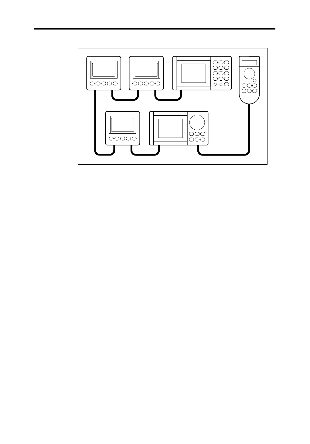
1.3 Additional Displays and F acilities
Because the RayData is compatible with the Raymarine SeaTalk
standard, and with the NMEA 0183 standard, it can be installed as part
of a larger system and display data sent by other instruments, such as a
navigation instrument or autopilot. A general diagram of such a system
is shown on the following page.
Page 12
Chapter 1: Introduction 3
2
2
Data Displayed
The RayData can display the following additional items of data, if the
appropriate information is available over a SeaTalk or NMEA interface:
• Heading
• Locked heading
• Position, as Lat/Long or TD
2
D3032-1
• Speed over ground (SOG)
• Course over ground (COG)
• Waypoint number
• Bearing to waypoint (BTW) and distance to waypoint (DTW)
• Time and date
• Cross track error (XTE) distance
• Time to go (TTG), estimated time of arrival (ETA) and velocity made
good (VMG) to the next waypoint
• Boat heading and rudder angle
Facilities
If the primary position data is lost, the RayData performs dead
reckoning calculations from the speed and heading data (if available),
and provides a DR position.
When heading information is available, the heading can be locked with a
simple keypress. The Locked Heading display then shows the locked
heading (Course to Steer) and the actual heading, plus a graphic offcourse indication.
Page 13

4 RAYDATA Installation and Operation Handbook
The RayData will display a subset of the SeaTalk alarms sent by other
instruments on the system, including Watch alarms. It can also send,
display and cancel a Man Overboard (MOB) warning.
Data Sent
The RayData’s primary function is to display data received from its own
transducers. However, if it is connected to other instruments via SeaTalk
interfaces, the following information is sent or repeated to these other
instruments:
• Depth, speed and sea temperature derived from direct-connected
transducers.
• MOB warning and MOB warning cancel.
• Data recognised from the NMEA input (such as magnetic variation), if
it is not already available on the system. This data is converted into
SeaTalk format.
Page 14

Chapter 2: Installation 5
Chapter 2: Installation
2.1 Introduction
This chapter explains how to install your RayData. If you are installing it
as a stand-alone unit, you will need to install the speed and depth
transducers and cables, and mount the RayData. If you are connecting
your RayData to a larger system, you should refer to the installation
instructions for the other units and for connection to the SeaTalk bus.
Note: Before attempting any installation, you should read the
Electromagnetic Compatibility (EMC) installation and service guidelines
provided in Section 2.2.
This chapter covers the following topics:
• Packing list
• Installing the depth and speed transducers
• Transducer cabling
• Mounting the RayData
• RayData connections
Page 15

6 RAYDATA Installation and Operation Handbook
2.2 EMC Installation and Service Guidelines
IMPORTANT NO TE
All Raymarine equipment and accessories are designed to the best
industry standards for use in the leisure marine environment.
Their design and manufacture conforms to the appropriate
Electromagnetic Compatibility (EMC) standards, but good installation is
required to ensure that performance is not compromised. Although
every effort has been taken to ensure that they will perform under all
conditions, it is important to understand what factors could affect the
operation of the product.
Installation
To avoid the risk of operating problems, all Raymarine equipment and
cables connected to it should be:
• At least 3 feet (1m) from any equipment transmitting or cables
carrying radio signals e.g. VHF radios, cables and antennas. In the
case of SSB radios, the distance should be increased to 7ft (2m).
• More than 7ft (2m) from the path of a radar beam. A radar beam can
normally be assumed to spread 20 degrees above and below the
radiating element.
• The equipment should be supplied from a different battery than the
one used for engine start. Voltage drops below 10v in the power
supply to our products can cause the equipment to reset. This will not
damage the equipment, but will cause the loss of some information
and can change the operating mode.
•Genuine Raymarine cables should be used at all times. Cutting and
rejoining these cables can compromise EMC performance and so
should be avoided unless doing so is detailed in this handbook.
• If a suppression ferrite is attached to a cable, this ferrite should not be
removed. If the ferrite has to be removed during installation it must be
reassembled in the same position.
Page 16

Chapter 2: Installation 7
Check Before Going to Sea
• Always check the installation before going to sea to make sure that it
is not affected by radio transmissions, engine starting etc..
• In some installations, it may not be possible to prevent the equipment
from being affected by external influences. In general this will not
damage the equipment but can lead to it resetting, or momentarily
may result in faulty operation.
Servicing and Safety
•Raymarine equipment should be serviced only by authorised Raymarine
service engineers. They will ensure that service procedures and
replacement parts used will not affect performance. There are no
user serviceable parts in any Raymarine product.
• Some products generate high voltages, and so never handle the
cables/connectors when power is being supplied to the equipment.
•Always report any EMC related problem to your nearest Raymarine
dealer. We will use any such information to improve our quality
standards.
2.3 Packing List
Your RayData display should be supplied with the following:
• Power lead
• SeaTalk daisy-loom plug to plug cable
• NMEA cable assembly, consisting of one 39in (1 metre) cable plus
two female lug connectors
• Sun cover
• Thumb studs (4)
• Thumb screws (4)
• This handbook
• RayData Quick Reference Card
Some packing options also include depth and speed transducers, as
described in the following section.
In addition, an optional trunnion mount kit is available.
Page 17

8 RAYDATA Installation and Operation Handbook
2.4 Installing the Depth and Speed Transducers
If you are installing your RayData as a stand-alone unit, you need to
install the depth transducer and the speed transducer (incorporating the
temperature transducer) that will be connected to the RayData.
The depth and speed transducers are normally supplied with detailed
installation and maintenance instructions. You must read these
instructions, together with the information in this chapter, before
attempting to install the transducers.
Transducer Type
The RayData is supplied in various configurations. Depending on your
choice, one of the following transducer sets is included:
• Plastic through hull depth and speed transducers, suitable for use with
Glass Reinforced Plastic (GRP), Steel and Aluminium hulls (with
system M78711).
Caution: Plastic through hull transducers must not be used on
vessels with wooden hulls.
• Bronze through hull depth and speed transducers, suitable for use
with fibreglass and wooden hull installations (with system M78709).
• Combined depth and speed bronze triducer (with system M78710).
The following transducers are also available as options:
• Retractable bronze depth transducer (part number M78717)
• Retractable plastic depth transducer (part number M78718)
• Plastic transom mount triducer (part number M78917)
• Bronze long-stem through hull triducer (part number M78918)
• In hull puck (part number M78919)
Page 18
Chapter 2: Installation 9
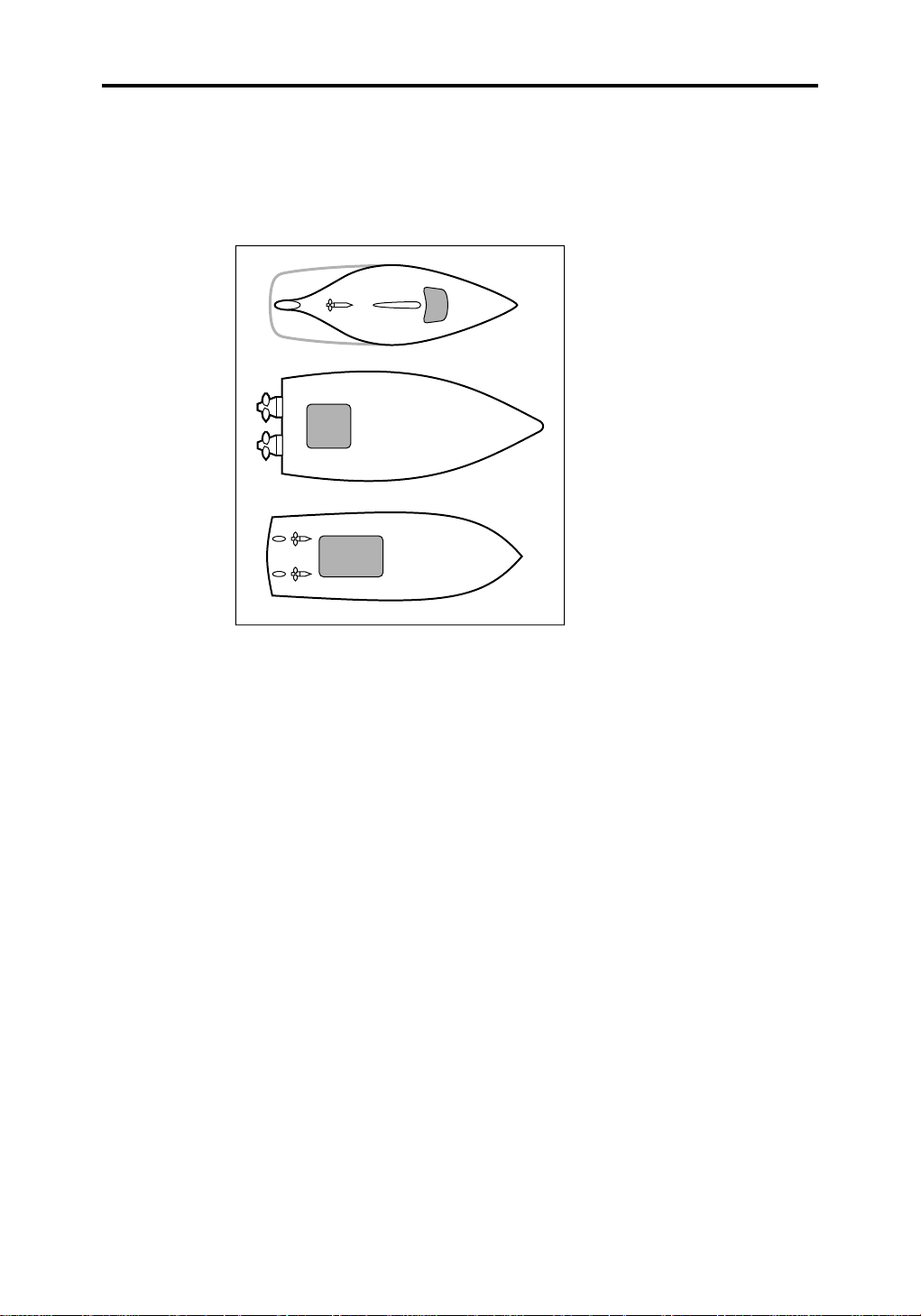
Installing the Speed T ransducer (Through Hull)
For accurate speed readings, locate the speed transducer in the
shaded ‘clear flow’ areas as shown.
D587
The transducer should also be:
• Ahead of propellers (10% W.L. length minimum)
• At least 6in (150mm) from the keel (with sailing yachts siting should
be forward of the keel)
• Near the centreline of the vessel
• Clear of other through hull fittings or projections
• Have sufficient clearance inside the hull to allow the nut to be fitted
• Have 4in (100mm) clearance above the through hull fitting for
withdrawal
Note: The speed transducer cable can, if required, be shortened.
However, new 1/8in lug connectors must be crimped to the shortened
cable.
Page 19
10 RAYDATA Installation and Operation Handbook
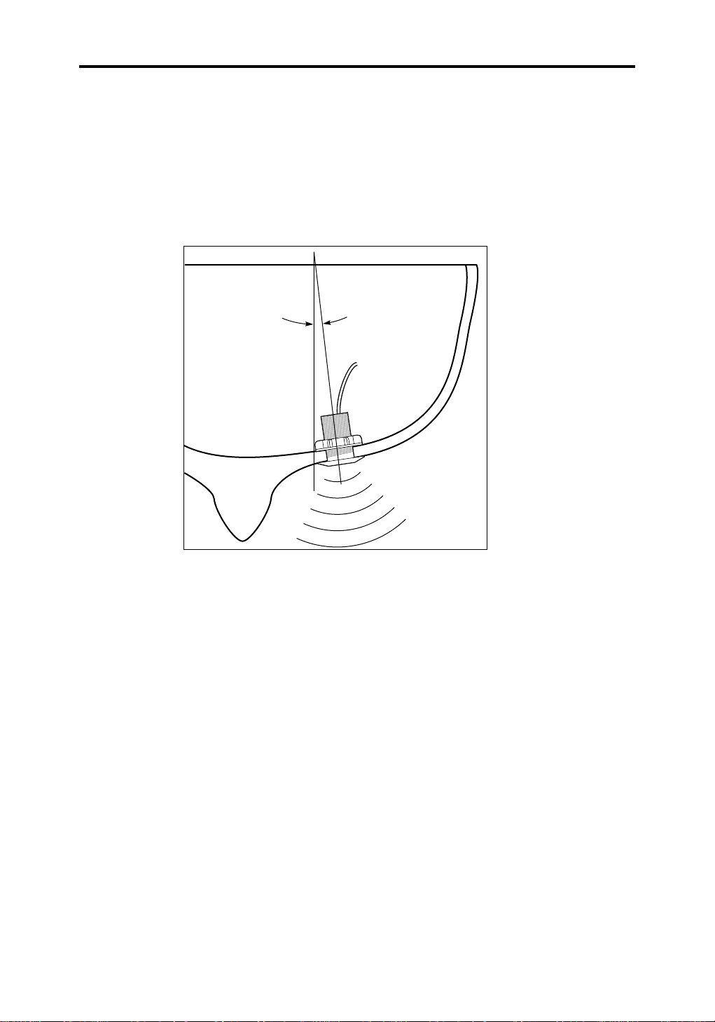
Siting of Depth T ransducer (Standard Through Hull)
The same mounting rules apply to the depth transducer as those listed
on the previous page for the speed transducer.
The depth transducer must be vertical to within 10°, forward, aft and
athwart ships.
10° Max
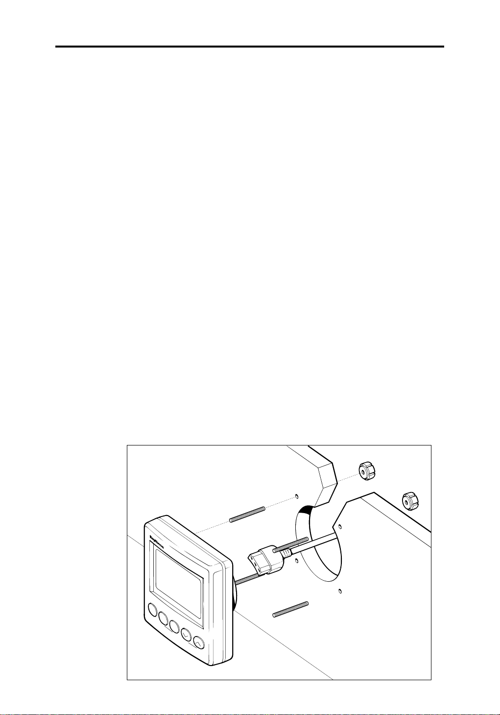
2.5 Transducer Cabling
The depth and speed transducers are supplied with 32.5ft (10m) of
cable. These cables are fitted with female lug connectors that plug
directly into the back of the RayData (see below).
Allow some slack in the cables, so that the equipment can be serviced if
necessary.
Run the transducer cable back to the instrument. Avoid fluorescent
lights, engines and radio transmitting equipment. The cables should
also be kept clear of the bilges and be secured at regular intervals.
Note: Do not change the length of the depth transducer cable: this
will affect the performance of the transducer. For further
information, please contact Raymarine or an authorized Raymarine
agent.
D630
Page 20
Chapter 2: Installation 11
2.6 Mounting the RayData
The RayData is waterproof and provided with a sun cover. It is
designed for above or below deck installation. You should mount it
where it is:
• Easily read by the helmsman
• Protected against physical damage
• At least 9in (230mm) from a compass
• At least 3ft (1m) from radio receiving equipment
• Accessible from behind for ease of installation and cable running
Although the RayData is designed to meet the CFR46 waterproofing
standard, it is advisable to mount it, whenever possible, so that it is not
exposed to the direct effects of salt spray or the hot sun.
The RayData can be mounted in two ways:
• On a panel (tabletop or console)
• Attached to a bulkhead or suspended overhead, using the optional
trunnion mounting kit
Panel Mounting
To mount the RayData on a tabletop or console:
1. Select a clear location at least 4.75in (120mm) square, that
conforms to the recommendations listed above.
NAV
POWER
DEPTH
SPEED
RAYDATA
MOB
LOCK
D3065-1
Page 21
12 RAYDATA Installation and Operation Handbook
Caution: Make sure there are no hidden electrical wires or other
items behind the desired location before proceeding.
2. Remove the mounting template (located just inside the rear cover of
this handbook), and attach it to the panel. Drill a pilot hole inside the
circular hole.
3. Using a suitable hole saw, cut a 3in (76mm) diameter hole to match
the pattern.
4. Drill four 3/16in (5mm) holes for the thumb studs.
5. Deburr the machined holes, and fix the RayData to the panel using
the four thumb studs and four thumb screws.
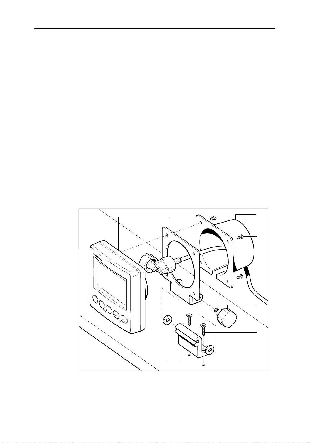
T runnion Mounting
To mount the RayData using the optional trunnion mounting kit:
1. Attach the trunnion surface mounting bracket (1) to the selected
mounting surface, using the two self-tapping countersunk
screws (2).
POWER
43
NAV
DEPTH
SPEED
RAYDATA
MOB
LOCK
17
5
6
8
2
D3036-1
1 Surface mounting bracket 2 Self-tapping countersunk screws 3 Unit bracket 4 RayData
5 Rear cover 6 Pan-headed screws 7 Rubber washers 8 Knobs
2. Place the unit bracket (3) over the boss of the RayData (4).
Page 22
Chapter 2: Installation 13
3. Make all the required connections to the back of the RayData, as
described in the following section, “RayData Connections”.
4. Place the rear cover (5) over the cables, and use the four pan-
headed screws (6) to fasten this cover and the unit bracket (3) to the
back of the RayData (4).
5. Attach the unit bracket (3) to the surface mounting bracket (1), with
the rubber washers (7) positioned between the two brackets, and
secure it in position using the knobs (8) provided.
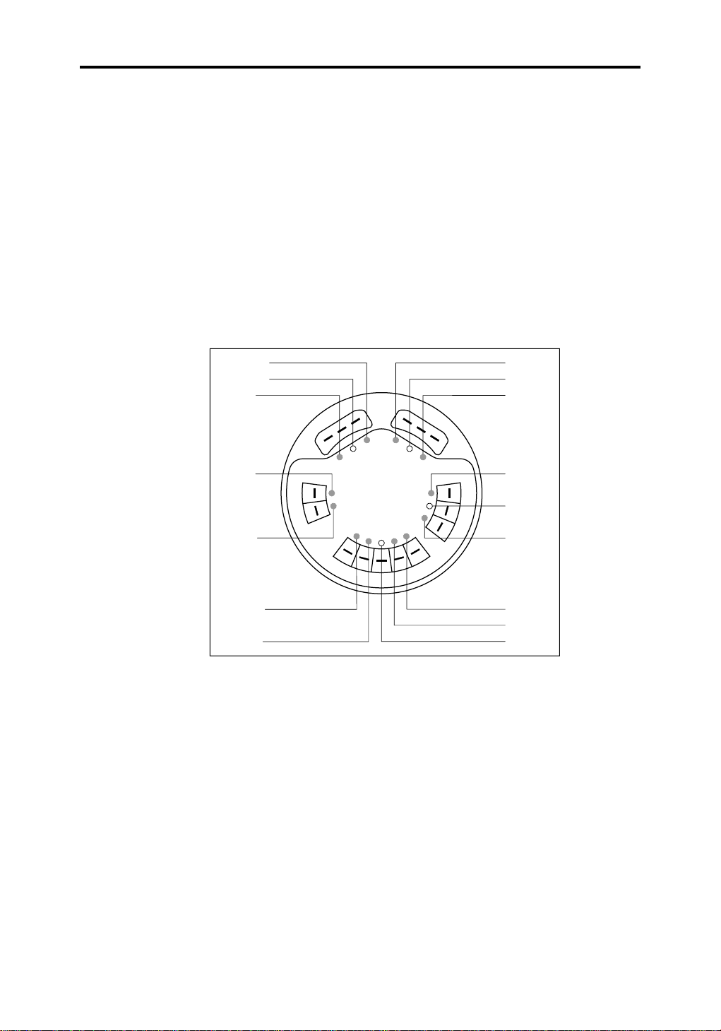
2.7 RayData Connections
Yellow
Screen
Red
Red
Blue
Brown
White
ss
SeaTalk
N
M
E
A
I
N
S
P
E
E
D
s
P
M
E
T
/
s
D
Red
Screen
Yellow
Blue
H
Screen
T
P
E
Black
Red
Green
Screen
D3056-1
The rear panel of the RayData has the following connectors:
1. Depth: 3 lug connectors
2. Speed & temperature: 5 lug connectors
3. NMEA input: 2 lug connectors
4. SeaTalk input and output: 2 sets of 3 lug connectors for power, data
and ground
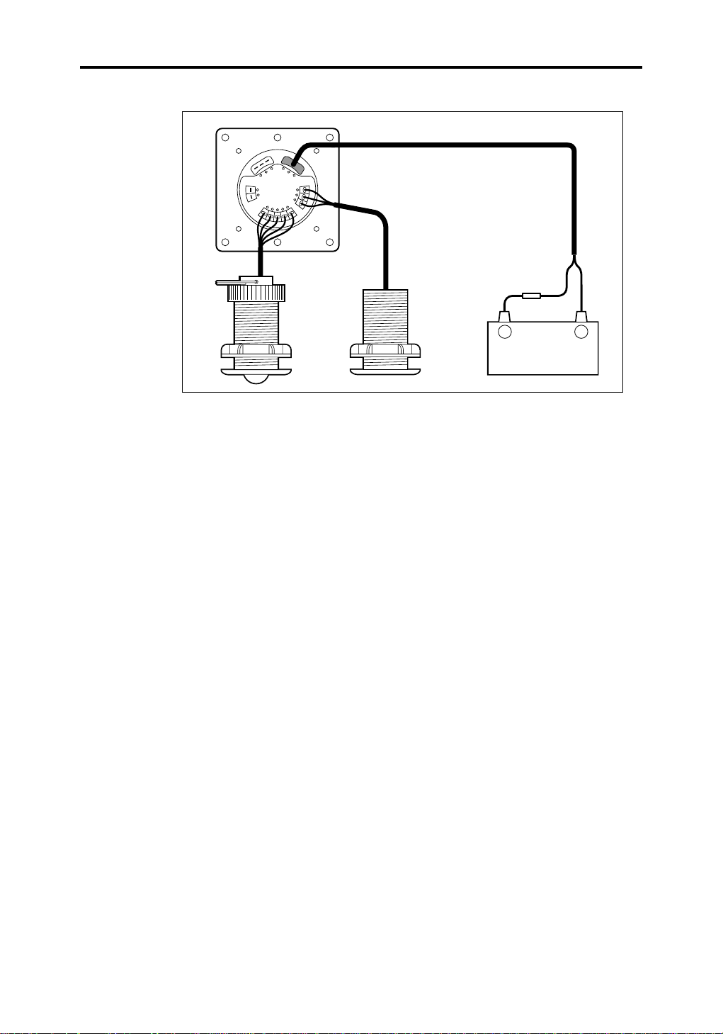
Stand-Alone System
If you are using the RayData as a stand-alone system, you will only need
to use the depth and speed connectors, together with the SeaTalk input
for power input, as shown in the following diagram.
Page 23
14 RAYDATA Installation and Operation Handbook
ss
SeaTalk
N
M
E
A
I
N
s
H
T
P
E
s
S
P
D
P
E
M
E
E
T
D
/
Fuse 5A
+
12VDC
Caution: The RayData must be connected to a 12V supply only.
Connect the power supply using the standard power cable supplied, as
follows:
1. Connect the molded power plug to one of the SeaTalk connections
on the rear of the RayData. Run the free end back to the vessel’s
12V DC distribution panel or battery.
2. Cut the cable to length and connect the red wire to 12V and the
screen to 0V. Protect the circuit with a 5A fuse/circuit breaker.
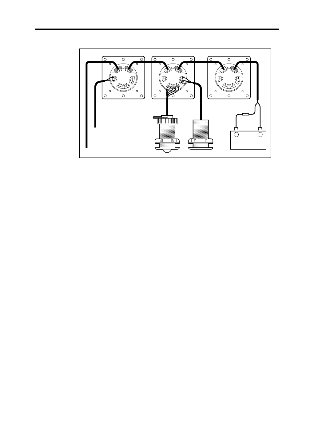
Larger System
If you are using the RayData as part of a larger system, you will need to
use the SeaTalk and/or NMEA connectors. You can still use the directlyconnected depth and speed transducers in this case.
The RayData can be connected to an existing SeaTalk system, using a
standard SeaTalk extension or interface cable connected to the SeaTalk
connectors on the rear of the RayData. The power supply and data are
passed from instrument to instrument via the daisy loom cable, as
shown in the following diagram.
+
D3037-1
Page 24
Chapter 2: Installation 15
N
M
E
A
I
N
NMEA in
SeaTalk in/out
and power
ss
SeaTalk
s
S
P
E
E
D
T
/
s
P
M
E
H
T
P
E
D
ss
SeaTalk
N
M
E
s
A
I
N
H
T
P
E
s
D
S
P
P
E
M
E
E
D
T
/
ss
SeaTalk
N
M
E
s
A
I
N
H
T
P
E
s
D
S
P
P
E
M
E
E
D
T
/
+
+
D3033-1
Page 25

16 RAYDATA Installation and Operation Handbook
Page 26

Chapter 3: Getting Started 17
Chapter 3: Getting Started
3.1 Introduction
This chapter introduces the RayData, explains how to turn it on and off,
describes the display and the functions of the keys, and explains how to
perform some basic operations.
It covers the following topics:
• Using the keys
• Turning the RayData on and off
• The display
• Changing the information displayed
• Changing the lighting
• Using the Locked Heading facility
• Man overboard (MOB)
Details of the functions of all the key presses are given in Appendix A.
Page 27
18 RAYDATA Installation and Operation Handbook
3.2 Using the Keys
The RayData is controlled using the five keys: NAV (POWER), DEPTH
(LIGHTS), SPEED,
ÚÚ
Ú
ÚÚ
and
ÙÙ
Ù
. The keys can be used singly or in
ÙÙ
combinations, so that operating your RayData is quick and simple.
There are two ways in which each key can be used:
• Press: Press the key momentarily and then release it.
• Press and hold: Press the key and hold it down for the length of time
stated (for example, three seconds), and then release.
As you press a key, a single beep confirms the key action. If the key
press is not valid for the current screen or mode, three beeps sound to
indicate that no response is available.
3.3 T urning the RayData On and Off
When you turn on the power to the RayData, the keys light up and the
LCD display shows the software version for three seconds. The screen
then automatically changes to show the data that was displayed when
the RayData was last used. If this is the first time the unit has been
turned on, the display shows the depth, as shown in the illustration
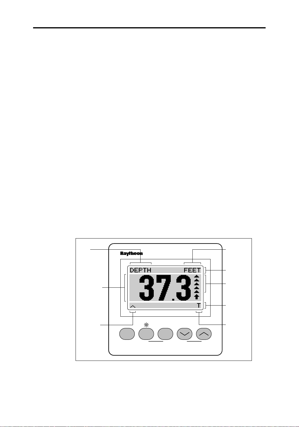
below.
Data
type
Data value
Sub-page
availability
indicator
RA YDAT A
NAV DEPTH SPEED
MOBPOWER LOCK
Units
Text
description
Trend
arrow
Additional
information
Depth
offset type
D3034-1
The data displays initially default to imperial units (knots, nautical miles
and feet), but you can change these as described in Chapter 4.
Page 28

Chapter 3: Getting Started 19
In low light levels, you can turn on and adjust the display backlighting
and contrast, as described later in this chapter (see Section 3.6).
To turn the RayData off, press and hold the NAV (POWER) key for
three seconds. The RayData display is cleared and the key lights go off.
The RayData is now in power-saving mode.
To turn the RayData on again, press and release the NAV (POWER)
key.
3.4 The Display
The display can show one to four items of data and their associated
information at one time. Such a set is called a page. The pages are
grouped into three main chapters, each of which is accessed using one
of the three main keys (DEPTH, SPEED or NAV). In addition, there is a
Setup chapter that allows you to set the defaults for your system (see
Chapter 4).
The main types of information shown on a display page are described
below, with reference to the illustration on the previous page.
Data Value
The single-line displays, such as the example depth display, each show
the data value in digits 1” (25mm) high, so that it is easy to read from a
distance. Other displays, such as the three-line page shown in page 21,
show more lines of data with smaller characters.
If no data is available for a displayed function, dashes are displayed
instead of the value.
T ext Description
A text description of the current function (such as DEPTH) is shown,
followed by the units of measurement. For example, for the Depth
function the units can be feet (FEET), metres (MTRS), or fathoms
(FATH). You can change the default units and other information, as
described in Chapter 4.
The position of the description depends on the type of display: for a
singe-line display, the text is in the top line; for a multi-line display, the
description is to the left of the data value, and the units to the right of the
value.
Page 29

20 RAYDATA Installation and Operation Handbook
T rend Arro w
To the right of the single-line data value, a trend arrow is provided on
the main depth and speed displays.
The direction of the arrow indicates whether the value is rising or falling.
For the Depth function, an up-arrow indicates that the bottom is coming
up: that is, the depth is decreasing.
The length of the trend arrow indicates the speed with which the value is
changing. The arrow consists of up to six segments. The more
segments are displayed, the greater the difference between the current
value and that shown in the previous update of the display.
Additional Information
Additional information may be shown along the bottom line of the page,
such as:
ÙÙ
• Whether you can display a different sub-page by pressing the
key: this is indicated by a Ù symbol in the lower left corner of the
screen
Ù
ÙÙ
• Which key(s) to press to perform an operation such as changing or
resetting a value (see Chapters 4 and 5)
• An alarm warning message (see Chapter 5)
• Information relating to the data, such as the depth offset
• A bargraph providing a graphical indication of, for example, steering
deviation or rudder angle
Note that the steering bargraphs are not linear: the first segment is
displayed with only a small deviation, the second when the deviation is
more than doubled and, when five segments are already displayed, a
very large increase in deviation is required before the sixth is displayed.
3.5 Changing the Information Displayed
You can display any of the information available to the RayData using
the five keys.
For example, when the main depth page is displayed, you can use the
DEPTH key to cycle through three main pages as follows:
1. With the main depth display on the screen, as shown on page 18,
press DEPTH to display the sea temperature.
Page 30

Chapter 3: Getting Started 21
D3039-1
2. Press DEPTH again to display a three-line page, showing the
depth, speed and temperature.
D3049-1
3. Press DEPTH a third time to return to the main depth display.
These are the three main pages in the Depth Chapter. Further
sub-pages are available using other keys.
ÙÙ
For example, with the main depth display on the screen, press the
key. The minimum depth that has been encountered is displayed, as
shown in the following example.
D3041-1
The Ù symbol in the bottom left corner of the screen indicates that
further screens are available: press
sub-pages, or
DEPTH to return to the main page.
ÚÚ
Ú
to move backwards. Alternatively, you can press
ÚÚ
ÙÙ
Ù
to move forwards through the
ÙÙ
Ù
ÙÙ
Page 31

22 RAYDATA Installation and Operation Handbook
Similarly, you can use the SPEED key to display the speed and log
pages in the Speed Chapter, and the NAV key to access any
navigational data that is received via SeaTalk or NMEA connections,
and displayed in the Nav Chapter pages.
The RayData Quick Reference Card, included with your RayData,
summarises the display pages available and the sequences in which
they are displayed. In addition, each page is described in detail in
Chapter 6.
3.6 Changing the Lighting
The level of lighting and contrast for the screen is controlled using the
DEPTH key, as indicated by the lamp symbol over the key on the
RayData front panel. The keys are always lit, so you will always be able
to read the key labels.
To change the screen lighting and contrast:
1. Press and hold the DEPTH key for one second. The lighting control
page appears. This is a temporary display, and reverts to the
previous page if you do not press a key for five seconds.
D3042-2
If the lighting was off before this page was displayed, the lighting is
automatically switched on at the highest level. If the lighting was
already on, the current lighting level is retained.
2. Press the DEPTH key to cycle through the lighting level options, HI,
LOW and OFF, until the required level is shown.
ÙÙ
ÚÚ
Ù
or
Ú
3. Press the
(in the range 1 to 16), until the required contrast level is shown.
After five seconds, or if you press SPEED, the display returns to the
page that was displayed before you selected the lighting control page,
with the new lighting and contrast levels. The contrast level is retained
until you reset it; the lighting level is retained until you reset it or turn the
RayData off.
ÙÙ
key to increase or decrease the contrast level
ÚÚ
Page 32

Chapter 3: Getting Started 23
3.7 Using the Locked Heading Facility
If your RayData is connected to other instruments which supply
heading information, you can use the RayData Locked Heading facility
to specify the heading on which you wish to steer.
Note: If you are using a SeaTalk connected autopilot, its locked
heading will over-ride the RayData’s locked heading, and will be
displayed on the RayData Locked Heading screen with a PILOT
HEADING indicator. The RayData facility does not control the
autopilot’s heading.
To select the current heading as the locked heading, simply press
ÚÚ
Ú
ÚÚ
key combination is used for a different purpose). The Locked Heading
page is displayed, as shown below.
and
ÙÙ
Ù
together from any page (except those that indicate that this
ÙÙ
D3064-1
This page shows both the locked heading and the current heading. The
steering bargraph allows you to see at a glance in which direction and
how far you are straying from the locked heading, and take corrective
action.
ÙÙ
ÚÚ
Ù
or
If you wish to change the locked heading, you can use the
keys to increase or decrease its value.
ÚÚ
To unlock the heading, press
Press DEPTH to return to the previous Depth Chapter page, or press
the SPEED or NAV key to display a different main page.
For further information, refer to the “Locked Heading” section at the end
of Chapter 6.
Ú
ÚÚ
and
ÙÙ
Ù
together again.
ÙÙ
ÙÙ
Ú
ÚÚ
Page 33

24 RAYDATA Installation and Operation Handbook
3.8 Man Overboard (MOB)
If your RayData is connected via SeaTalk to other instruments with the
facility to handle “man overboard” (MOB) calculations, you can send
and cancel MOB warnings. Note that no waypoint data will be sent by
the RayData.
Sending an MOB W arning
To send an MOB warning, press the DEPTH and SPEED keys
together, as indicated by the MOB label on the RayData front panel. An
audible alarm sounds (unless this has been disabled using the Setup
option, as described in Chapter 4).
If there is no MOB Master instrument on your SeaTalk system, the
RayData screen will display the message “MOB NOT AVAILABLE”.
If an MOB Master on the SeaTalk system responds, the audible alarm
stops and an MOB page such as the following is displayed:
D3071-1
This shows the location and distance of the MOB point you need to
steer towards, together with a steering bargraph. It is a special version
of the Waypoint/Bearing/Distance page (see page 56).
The MOB page is also displayed if a SeaTalk MOB message is
received from other instruments.
Note: Certain models of Raymarine chart plotters will respond to an
MOB warning from the RayData, and track to the MOB location, but will
not return the data for the RayData to display. In this case, you can turn
off the audible alarm by pressing any key. The message “MOB NOT
AVAILABLE” will be displayed until you cancel the MOB.
Page 34

Chapter 3: Getting Started 25
Cancelling an MOB W arning
To cancel an MOB warning, press and hold the DEPTH and SPEED
keys for one second. The MOB information is cleared and the display
reverts to the Waypoint/Bearing/Distance page.
The MOB warning will also be cancelled if an appropriate message is
received from another instrument via the SeaTalk connection.
3.9 Key Functions
The five keys have the following main functions:
• NAV (POWER) is used to:
- Turn the RayData on and off
- Access the Nav Chapter of display pages, if the RayData is
receiving navigation data via the SeaTalk and/or NMEA
connection
• DEPTH (LIGHTS) is used to:
- Access the Depth Chapter of display pages, which include depth
and temperature displays and alarm controls
- Control the lighting and contrast level for the screen, and the
lighting level for the keys
• SPEED is used to:
- Access the Speed Chapter of display pages, which include speed
and log displays
- In combination with DEPTH, send/cancel an MOB warning
ÚÚ
Ú
•
ÚÚ
-
-
-
The key functions, including the combination key-press functions, are
detailed in the table in Appendix A.
ÙÙ
and
Ù
are used as follows:
ÙÙ
ÙÙ
Ù
to move forwards through the available sub-pages, increase a
ÙÙ
value, or move forwards through setup options
ÚÚ
Ú
to move backwards through the available sub-pages, decrease
ÚÚ
a value, or scroll backwards through setup options
ÚÚ
Ú
ÚÚ
heading, reset a value or make a selection
and
ÙÙ
Ù
together to perform operations such as lock/unlock the
ÙÙ
Page 35

26 RAYDATA Installation and Operation Handbook
Page 36

Chapter 4: Setup and Calibration 27
Chapter 4: Setup and Calibration
4.1 Introduction
This chapter explains how to set up the defaults for your RayData.
These control the way in which information is displayed on the
RayData, such as the numerical units used and the time format. It also
explains how to calibrate the speed value for your vessel.
The RayData is pre-programmed with factory default settings. If you
change any of these, the new defaults will remain set, even if the power
is disconnected, unless you perform a factory reset as described in
Chapter 7.
You should set up and calibrate your RayData as soon as possible after
installation. Changing the defaults at a later date may have unexpected
results: for example, if you change the distance units from nautical miles
to kilometres after travelling 50nm, the log recording the total distance
travelled will then read 50km.
You should keep a record of the default settings you have changed.
This chapter covers the following topics:
• Using the Setup pages
• Setup options
• Speed calibration
Note: As it leaves the factory, the RayData is set to Master for depth,
speed and temperature data: that is, it is set up to receive data from
directly connected speed and depth transducers (or, if there are no
directly-connected transducers, from NMEA). If the RayData is being
used as a Repeater for SeaTalk depth, speed and temperature data,
you must specify this in the setup procedure, otherwise this data will not
be displayed.
Note: When repeating speed and depth information from NMEA, the
calibration values, alarms and depth offset have no effect.
Page 37

28 RAYDATA Installation and Operation Handbook
4.2 Using the Setup Pages
To access the Setup pages, press NAV and
page is displayed:
This is the first of the Setup pages, and shows the Depth Units menu,
with the current default value highlighted. The initial default setting for
depth units is FEET.
To change the RayData defaults:
ÙÙ
ÚÚ
Ù
or
Ú
1. Use the
available menus, without affecting the current settings. Some menus
consist of lists of options, from which you can select the appropriate
one. Others consist of a value that you can increase of decrease.
The options are listed in Section 4.3.
ÙÙ
key to scroll forwards or backwards through the
ÚÚ
ÙÙ
Ù
together. The following
ÙÙ
D3040-1
2. When the required menu is displayed, press
select the menu. The menu title is highlighted.
3. Use the
decrease or increase the value displayed.
4. When you have highlighted the required option, or set the value
correctly, press
as the new default, and moves on to the next menu.
5. Repeat steps 1 to 4 until you have set all the required defaults.
6. Return to the last-used non-Setup page by pressing NAV and
together. All the new entries are then validated.
4.3 Setup Options
The following table lists the Setup menus and their options, shows the
factory default setting, and provides a space for you to make a note of
your new default setting. Use the
menus in the order shown, or
ÚÚ
Ú
ÚÚ
ÚÚ
Ú
and
ÚÚ
ÙÙ
or
Ù
key to scroll down or up the menu options, or to
ÙÙ
ÚÚ
Ú
ÚÚ
and
ÙÙ
Ù
together. This enters the option or value
ÙÙ
ÙÙ
Ù
key to scroll forwards through the
ÙÙ
ÚÚ
Ú
to scroll backwards.
ÚÚ
ÙÙ
Ù
together to
ÙÙ
ÙÙ
Ù
ÙÙ
Page 38

Chapter 4: Setup and Calibration 29
Menu Options Factory New
Default Default
Depth Units FEET FEET
METRES
FATHOMS
Depth Offset Value 0
Sounder Control ON ON
OFF
Audible Alarm ON ON
OFF
Speed Units KMH KNOTS
MPH
KNOTS
Temperature Units DEG C DEG F
DEG F
Distance Units KM NM
SM
NM
Position LAT LON LAT LON
TD (only with NMEA input )
Variation Variation value: 0
plus [W] or minus [E] up to
30°, in whole degrees
True/Magnetic Mode TRUE MAGNETIC
MAGNETIC
Depth Response Level 1 - 15 4
Speed Response Level 1 - 15 4
Temperature Response Level 1 - 15 4
Heading Response Level 1 - 15 4
Time Format 12 HOUR 24 HOUR
24 HOUR
Time Offset Offset value: 0
Plus or minus up to 12 hours,
in whole hours
Page 39

30 RAYDATA Installation and Operation Handbook
Menu Options Factory New
Default Default
Simulator ON OFF OFF
OFF
Speed Mode REPEATER MASTER
MASTER
Depth Mode REPEATER MASTER
MASTER
Most of the menus and options are self-explanatory. The following
subsections provide further information about the remainder.
Depth Offset
Without a depth offset, the depth value displayed on the RayData will
be the distance from the transducer to the bottom. You can adjust the
offset value to give the depth from either of the following:
• Keel: Reduce the depth offset value to set it to the distance between
the transducer and the keel, as a negative value
• Waterline: Increase the depth offset value to set it to the distance
between the waterline and the transducer, as a positive value
The Depth page displays an indication of the type of offset (Keel,
Waterline or Transducer) based on whether you set a negative or
positive value here, or leave the value set to zero.
Note: If you have just changed the depth units in the previous setup
page, the units for the depth offset calibration will not be updated until
you have left the Setup Chapter and then reselected it.
When you adjust the depth offset, the maximum value (positive or
negative) and the resolution you can enter depends on the depth units,
as follows:
Units Maximum Resolution
Feet 10.0 0.1
Metres 3.0 0.1
Fathoms 2.0 0.1
Page 40

Chapter 4: Setup and Calibration 31
Sounder Control
The Sounder Control menu allows you to turn the internal depth
sounder transmitter off, without switching off the RayData. You may
wish to do this if it would otherwise interfere with other equipment, such
as a fish-finder. Use the Setup menu to turn the sounder on again when
required.
If you set the RayData Depth Mode to Repeater (see below), the
sounder is turned off automatically.
Response Level
The Response Level settings control the update rate of the display, for
depth, speed, temperature or heading inputs. Select a value in the
range 1 - 15 seconds. Use a larger response level value to see rapid
changes in the data value, or a smaller response level value to smooth
out changes in the data value.
Mode
The Speed Mode and Depth Mode must be set to indicate the way in
which your system is set up, as follows:
• Leave the mode set to Master if the transducer is connected to the
RayData directly, or if you wish to repeat depth and/or speed and
temperature information from NMEA.
• Set the mode to Repeater if the RayData is primarily a remote
display.
You can only have one Master setting for each mode on your system.
Refer to Appendix B, “Data Sources”, for further information.
4.4 Speed Calibration
You need to calibrate the speed transducer to ensure that the value
displayed on the RayData is accurate.
When making a calibration, the transducer’s apparent speed reading is
compared with the known speed, determined by travelling a known
distance and recording the time taken. The factor required to correct the
transducer’s speed reading is stored by the RayData or entered
manually as a calibration factor. The factor is applied to the speed
transducer data to obtain the correct value on the display.
Page 41

32 RAYDATA Installation and Operation Handbook
There are two methods of updating the speed calibration:
• Automatic calibration. You travel a known distance, and the
RayData calculates and stores the required calibration factor.
• Manual calibration. If you know the calibration factor required for
your vessel, or if you wish to calculate it yourself, you can set the
RayData’s speed calibration value.
In both cases, you need to use the Speed Calibration option from the
Setup pages, as described on the following pages for each method.
Automatic Calibration
To calibrate the speed automatically, run between two points a known
distance apart while the RayData monitors the speed data. You can
perform up to four calibration runs, and the RayData averages the
information to obtain the calibration factor that will be used to correct the
speed data displayed.
Select an easily identifiable measured distance from the chart (between
0.5 and 1.0nm), and carry out the calibration when the tide flow is least.
You should complete a minimum of two runs, one in each direction, to
cancel the tidal effect.
To perform the speed calibration:
1. If one of the Setup pages is not currently displayed, press NAV and
ÙÙ
Ù
together to display the first Setup page.
ÙÙ
2. Press SPEED. The Auto Speed Cal page is displayed.
D3043-2
The display shows that the current calibration run number is 1, and
provides a default of 1.00nm for the length of the calibration run.
ÙÙ
Ù
3. Use the
the calibration run length, until it matches the length of the
calibration distance you plan to use for this run. You cannot change
the distance units here.
key to increase or the
ÙÙ
ÚÚ
Ú
key to decrease the value of
ÚÚ
Page 42

Chapter 4: Setup and Calibration 33
4. When your vessel reaches the start point for the first calibration run,
press SPEED to start the run. The display indicates that the run is in
progress.
5. When you reach the end point of the run, press SPEED again to
stop the measurement.
The display returns to the Auto Speed Cal page.
6. If you wish to continue calibration with the next run, press DEPTH to
increase the run number by one. If you were not happy with the run,
you can leave the run number the same and repeat the current run
now, or continue now and repeat the run later.
7. Repeat steps 4 to 6 until you have completed all the runs. If all four
runs have been completed, when you press DEPTH the run number
returns to 1: if any of the runs were incorrect, you can use the
DEPTH key to select the required run number and then repeat the
run if required.
8. Press NAV to exit. The Exit Speed Setup page is displayed.
9. Press SPEED to store the new calibration factor. Alternatively, press
NAV to cancel all changes.
The last-used Setup page is displayed. Press NAV and
to return to normal operation.
Manual Calibration
If you already know the correct calibration factor, or have calculated it
yourself by timing a known distance run, you should adjust the
RayData’s calibration value as follows:
1. If one of the Setup pages is not currently displayed, press NAV and
ÙÙ
Ù
together to display the first Setup page.
ÙÙ
2. Press SPEED. The Auto Speed Cal page is displayed (see above).
3. Press NAV to exit. The Exit Speed Setup page is displayed.
4. Press DEPTH to display the Manual Speed Cal page.
ÙÙ
Ù
together
ÙÙ
D3044-1
Page 43

34 RAYDATA Installation and Operation Handbook
The display shows a calibration value of 1.00 (no calibration factor).
ÙÙ
Ù
5. Use the
required.
6. Press
NAV to cancel all changes.
The last-used Setup page is displayed. Press NAV and
to return to normal operation.
key to increase or the
ÙÙ
ÚÚ
Ú
ÚÚ
and
ÙÙ
Ù
together to set the new value. Alternatively, press
ÙÙ
ÚÚ
Ú
key to decrease the value as
ÚÚ
ÙÙ
Ù
together
ÙÙ
Page 44

Chapter 5: Alarms 35
Chapter 5: Alarms
5.1 Introduction
This chapter explains how to set alarm limits and turn alarms on and off,
and how to handle alarms when they activate.
The alarm values that you set are limits. If the value received from a
sensor falls outside the range set by the upper and lower alarm values,
the result is an active alarm condition which is reported with a visual
message and, depending on your setup selection, an audible signal.
You can turn an alarm off so that it will not activate. In this case, the
alarm limit value is retained, and redisplayed when you turn the alarm
on again.
The RayData provides the following types of alarm:
• Shallow depth alarm, which is activated when the water is shallower
than the specified depth . Set this alarm to a value greater than the
depth at which you will ground, to allow yourself time to respond to
the alarm; allow a greater margin if you are in areas where the bottom
can shelve steeply.
• Deep depth alarm, which is activated when the water exceeds the
specified depth. This is useful when locating fishing grounds, or when
moving offshore away from coastal waters.
• Anchor alarm, which is activated when the depth becomes more
than or less than the values you have specified. In addition to its
usefulness in monitoring the depth of the anchored position, the
anchor alarm can also be used to help you maintain position on a
suitable depth-limited fishing ground, without having to reset the
normal shallow and deep alarm limits.
• Temperature alarm, which is activated when the surface sea
temperature becomes more than or less than the values you have
specified. This alarm is useful for locating warm currents or streams
for fishing, or to let you know when the water temperature is suitable
for swimming.
Note: When repeating depth and temperature information from NMEA,
the alarm settings have no effect.
Page 45

36 RAYDATA Installation and Operation Handbook
5.2 Setting Alarms
Alarms can be set for the following data:
• Depth: Shallow and Deep, reported as two separate alarms
• Anchor: Lower and Upper limits
• Temperature: Lower and Upper limits
When you first install your RayData, the alarms are set as follows:
Alarm Limit Value On/Off
Depth Shallow 10 feet ON
Depth Deep 100 feet OFF
Anchor Lower 30 feet OFF
Upper 60 feet OFF
Temperature Lower 32 °F OFF
Upper 90 °F OFF
All the display pages that deal with setting alarms are part of the Depth
Chapter, and are accessed as shown in the diagram below.
DEPTH
MAIN
DEPTH
DEPTH
SEA
TEMP
DEPTH
SPEED
DEPTH
TEMP
Press DEPTH key to return to main page
MINIMUM
DEPTH
++++
Reset minimum
TEMP
ALARM
+
TEMP
ALARM
ADJUST
SHALLOW
ALARM
SHALLOW
ALARM
ADJUST
DEPTH
DEEP
ALARM
DEEP
ALARM
ADJUST
ANCHOR
ALARM
ANCHOR
ALARM
ADJUST
PAGES
The units for the alarm limits are the same as those set for the depth
and temperature using the Setup pages (see Chapter 4).
Note: On SeaTalk systems, these alarms are global. Any unit on the
system, including the RayData, can set or change the alarm values,
and switch the alarms on or off. The new settings are shown on all the
other units.
D3066-1
Page 46

Chapter 5: Alarms 37
T urning Alarms On and Off
You can turn any RayData alarm off so that it will not activate. For
example, may wish to disable the anchor alarm while you are cruising.
This is not the same as acknowledging an alarm when it becomes
active, which is described in Section 5.3.
The alarm status is shown on the appropriate alarm page: if the alarm is
on, the current alarm limit value(s) is displayed; if it is off, the text
“ALARM OFF” is displayed.
ÚÚ
To disable the alarm, press and hold
seconds. The value(s) is replaced by the text “ALARM OFF”.
To turn the alarm back on, press and hold
seconds again. The current alarm limit value(s) is displayed.
Note that you can adjust the alarm limits, as described below,
irrespective of whether the alarm is on or off.
Ú
ÚÚ
and
ÚÚ
Ú
ÚÚ
ÙÙ
Ù
together for six
ÙÙ
D3072-1
ÙÙ
and
Ù
ÙÙ
Adjusting the Shallow Alarm Limit
The minimum and maximum alarm depths you can select, and the
resolution of the alarms, depend on the units selected as follows:
together for six
Units Minimum Maximum Resolution
Depth Depth
Feet 3 30 Tenths of feet
Fathoms 0.5 5 Tenths of fathoms
Metres 1 9 Tenths of metres
The shallow alarm limit must be less than the deep alarm limit.
Page 47

38 RAYDATA Installation and Operation Handbook
To adjust the shallow depth alarm value:
1. Press DEPTH to access the last-used Depth Chapter main page. If
this is not the Main Depth page, press DEPTH again to cycle
through the Depth Chapter pages until the Main Depth page is
displayed (see Section 3.5).
ÙÙ
Ù
2. Press the
3. Press the
key to display the Minimum Depth sub-page.
ÙÙ
ÙÙ
Ù
key again to display the Shallow Alarm sub-page.
ÙÙ
D3047-1
This shows the current alarm threshold value, or ALARM OFF if the
alarm is turned off. To toggle the alarm between on and off, press
and hold
4. Press
displayed.
5. Press
operate as follows:
Press and release the key to change the right-most digit by one.
For example, if the display value is 11.1, when you press the
the value will increase to 11.2. If the display value is 111, the value
will increase to 112.
ÚÚ
Ú
ÚÚ
ÚÚ
Ú
and
ÚÚ
ÙÙ
Ù
to increase the value, or
ÙÙ
ÙÙ
and
Ù
together for six seconds.
ÙÙ
ÙÙ
Ù
together. The Shallow Alarm Adjust page is
ÙÙ
D3050-1
ÚÚ
Ú
to decrease it. The keys
ÚÚ
ÙÙ
Ù
ÙÙ
key
Press and hold the key to change the value more rapidly. The
value stops changing after you release the key.
Page 48

Chapter 5: Alarms 39
6. When you have set the value to the required number, press
ÚÚ
Ú
ÚÚ
value set.
and
ÙÙ
Ù
together to exit to the Shallow Alarm page, with the new
ÙÙ
ÚÚ
7. If the alarm is off, press and hold
to turn it on. The current alarm value is displayed.
If you do not wish to adjust the deep alarm limits, press DEPTH to return
to the Main Depth page.
Ú
ÚÚ
and
ÙÙ
Ù
together for six seconds
ÙÙ
Adjusting the Deep Alarm Limit
The minimum and maximum alarm depths you can select, and the
resolution of the alarms, depend on the units selected as follows:
Units Minimum Maximum Resolution
Depth Depth
Feet 10 400 Whole feet
Fathoms 2 50 Whole fathoms
Metres 3 120 Whole metres
The deep alarm limit must also be greater than the shallow alarm limit.
To adjust the deep depth alarm value:
1. Unless you are continuing after setting the shallow alarm, follow
steps 1 to 3 in the Shallow Alarm procedure (page 38).
ÙÙ
Ù
2. Press the
current alarm limit, or ALARM OFF if the alarm is turned off. To
toggle the alarm between on and off, press and hold
together for six seconds.
3. Press
displayed.
4. Adjust the value to the required setting, as described in step 5 in the
Shallow Alarm procedure (page 38).
5. Press
Alarm page.
6. If the alarm is off, press and hold
to turn it on. The current alarm value is displayed.
Press DEPTH to return to the Main Depth page, or
the Anchor Alarm page.
key to display the Deep Alarm sub-page, showing the
ÙÙ
ÚÚ
Ú
ÚÚ
ÚÚ
Ú
ÚÚ
and
and
ÙÙ
Ù
together. The Deep Alarm Adjust page is
ÙÙ
ÙÙ
Ù
together to set the value and return to the Deep
ÙÙ
ÚÚ
Ú
ÚÚ
and
ÙÙ
Ù
together for six seconds
ÙÙ
Ù Ù
Ù
to move on to
Ù Ù
ÚÚ
Ú
ÚÚ
and
ÙÙ
Ù
ÙÙ
Page 49

40 RAYDATA Installation and Operation Handbook
Adjusting the Anchor and Temperature Alarm Limits
The anchor and temperature alarm thresholds are both set in the same
way. The anchor alarm is used in the example displays.
For the anchor alarm, the minimum and maximum alarm depths you
can select, and the resolution of the alarms, are the same as for the
shallow and deep alarms.
For the temperature alarm, the range is 5 to 104°F (-10 to +40°C), with a
resolution of 0.1°.
To adjust the anchor or temperature alarm values:
1. Display the appropriate alarm page:
ÙÙ
Ù
- For the anchor alarm, press
described above, or
- For the temperature alarm, use the DEPTH key as many times
as required to display the Temperature page, and then
ÙÙ
Ù
ÙÙ
.
press
Ú Ú
Ú
from the Main Depth page.
Ú Ú
from the Deep Alarm page
ÙÙ
D3048-1
The page shows the current alarm limits, or ALARM OFF if the
alarm is turned off. To toggle the alarm between on and off, press
and hold
2. Press
ÚÚ
Ú
ÚÚ
ÚÚ
Ú
ÚÚ
and
ÙÙ
and
Ù
together for six seconds.
ÙÙ
ÙÙ
Ù
together. The lower adjust page is displayed.
ÙÙ
D3070-1
Page 50

Chapter 5: Alarms 41
3. Press
4. When you have set the value to the required number, press
5. When you have set the value to the required number, press
6. If the alarm is off, press and hold
The new values are now set. Press DEPTH or
Depth page.
ÙÙ
Ù
to increase the value, or
ÙÙ
step 5 in the Shallow Alarm procedure (page 38).
ÚÚ
Ú
ÚÚ
step 3 to adjust the value.
ÚÚ
Ú
ÚÚ
to turn it on. The current alarm limits are displayed.
and
and
ÙÙ
Ù
together to display the upper adjust page, and repeat
ÙÙ
ÙÙ
Ù
together to return to the Alarm page.
ÙÙ
5.3 Handling Alarms
The RayData will respond to the alarms set internally, as well as any
external Watch alarms received from other instruments via the SeaTalk
connection.
Alarm Notification
ÚÚ
Ú
to decrease it, as described in
ÚÚ
ÚÚ
Ú
ÚÚ
and
ÙÙ
Ù
together for six seconds
ÙÙ
Ù Ù
Ù
to return to the Main
Ù Ù
When a data value goes outside the limits set for the depth, anchor or
temperature alarms, a text message is displayed on the RayData
screen and, if requested, an audible alarm sounds. You can select
whether or not an audible alarm sounds using the Setup pages (see
Chapter 4).
The text message appears in reversed video (white on a black
rectangle), and shows the name of the alarm that is currently active, as
shown in the example below.
D3045-1
Note: The alarm message is shown on the current data display, even if
it does not relate to the data on that page.
Page 51

42 RAYDATA Installation and Operation Handbook
If more that one alarm is active, the alarms will be handled in order of
priority, as follows:
1. Watch alarm
2. Shallow alarm
3. Anchor alarm
4. Deep alarm
5. Temperature alarm
Dealing with an Alarm
To silence an audible alarm, press any key. This turns the audible alarm
off for 30 seconds. If, after this period, the alarm condition still exists, the
audible alarm will sound again.
The alarm text message remains on the display, and the SeaTalk alarm
remains active, until the data value returns within the safe limits set.
You may wish to adjust the alarm limits, depending on the current
temperature or depth conditions, or to disable an alarm completely.
These procedures are described in Section 5.2. You can also disable
the audible alarm by selecting the appropriate option in the Setup
pages (see Chapter 4).
If your system includes a SeaTalk autopilot with a Watch alarm facility,
the RayData will respond to a Watch alarm but cannot set it or disable it.
You can acknowledge a Watch alarm by pressing any key, which turns
off the audible alarm for three minutes.
Page 52

Chapter 6: The Display Pages 43
Chapter 6: The Display Pages
6.1 Introduction
The RayData can display a wide range of information in the form of
pages, which are grouped into chapters. Each of the main chapters Depth, Speed and Nav - is accessed directly using a dedicated key.
When you press the NAV, SPEED or DEPTH key to access the
required chapter, the page displayed is the main page that was used
last from that chapter.
This chapter of the handbook provides reference information on the
following:
• The Depth Chapter, which includes depth, temperature and threeline pages
• The Speed Chapter, which includes speed, log and three-line pages
• The Nav Chapter, which includes navigation pages, if the RayData is
connected to other instruments that make this information available
For each chapter, the individual pages (and their sub-pages) are
described in detail, excluding the the alarm setup pages which are
described in Chapter 5. The pages in the Setup Chapter are described
in Chapter 4.
For instructions on operating the RayData, and general information on
the displays, refer to Chapter 3, “Getting Started”, and to the RayData
Quick Reference Card included with your RayData.
Note: Each page description includes information on the effect of key
presses that are specific to that page. The following key press
combinations have the same effect, irrespective of the page displayed
when they are pressed:
Keys Page Displayed
ÚÚ
ÙÙ
Ú
+
Ù
ÚÚ
ÙÙ
SPEED+DEPTH MOB page (see Section 3.8)
Locked Heading page, unless the current page
indicates that this key combination is used for a
different purpose (see Section 3.7)
ÙÙ
NAV+
Ù
ÙÙ
Refer to the Key Functions table in Appendix A for further information.
First Setup Chapter page (see Chapter 4)
Page 53

44 RAYDATA Installation and Operation Handbook
6.2 The Depth Chapter
The Depth Chapter consists of three main pages and 10 sub-pages, as
shown in the diagram below.
DEPTH
MAIN
DEPTH
DEPTH
SEA
TEMP
DEPTH
SPEED
DEPTH
TEMP
Press DEPTH key to return to main page
MINIMUM
DEPTH
++++
Reset minimum
TEMP
ALARM
+
TEMP
ALARM
ADJUST
SHALLOW
ALARM
SHALLOW
ALARM
ADJUST
DEPTH
This section describes the following pages:
• Main Depth
Minimum Depth
Shallow Alarm
Deep Alarm
DEEP
ALARM
DEEP
ALARM
ADJUST
ANCHOR
ALARM
ANCHOR
ALARM
ADJUST
PAGES
D3066-1
Anchor Alarm
• Sea Temperature
Temperature Alarm
• 3-Line Page (speed, depth and temperature)
The pages dealing with setting alarms are described in detail in
Chapter 5.
Main Depth
To display this page, press DEPTH from any page. If one of the Depth
Chapter pages is already displayed, or if this page was not the last-used
Depth Chapter page, press DEPTH again to cycle through the Depth
pages until this page is displayed.
Page 54

Chapter 6: The Display Pages 45
D3038-1
This display shows the depth in metres, feet or fathoms, depending on
the choice made in the Setup pages (see Chapter 4). The letter in the
lower right corner indicates the depth offset: that is, whether the depth is
measured from the keel (K), waterline (W) or transducer (T). The depth
offset is determined by the Setup selection, together with the response.
Note: If the depth data is being repeated from NMEA, the alarms and
depth offset specified for the RayData have no effect, and no depth
offset letter is displayed.
The trend arrow at the right edge of the display indicates the direction
and rate of change of the depth. An upwards arrow means that the
bottom is rising: that is, the depth is decreasing.
The length of the trend arrow indicates the speed with which the value is
changing. The arrow consists of up to six segments, including the arrow
head. The more segments are displayed, the greater the difference
between the current value and that shown in the previous update of the
display.
An alarm indicator (shallow or deep) is displayed at the bottom of any
screen if the depth value is outside the specified safe range, as
described in Chapter 5.
If the depth echo is lost, the display shows dashed lines for the missing
depth value, together with the last depth reading received, as shown in
the following example.
D3046-1
Page 55

46 RAYDATA Installation and Operation Handbook
Minimum Depth
To display this sub-page, press
This page shows the minimum depth that has been encountered since
the value was last reset. The units and depth offset are the same as
those for the Main Depth value.
To reset the minimum depth value, press
current depth will be displayed as the new minimum depth.
ÙÙ
Ù
from the Main Depth page.
ÙÙ
D3041-1
ÚÚ
Ú
ÚÚ
and
ÙÙ
Ù
together. The
ÙÙ
Shallow Alarm
To display this sub-page, press
or twice from the Main Depth page.
ÙÙ
Ù
once from the Minimum Depth page,
ÙÙ
D3047-1
This page shows the current setting of the depth limit value that will set
off a shallow alarm or, if the alarm has been turned off, the text “ALARM
OFF”. The units and depth offset are the same as those for the Main
Depth value.
ÚÚ
Press and hold
alarm either from off to on or from on to off.
For detailed information on using and setting alarms, refer to Chapter 5.
Ú
ÚÚ
and
ÙÙ
Ù
together for three seconds to toggle the
ÙÙ
Page 56

Chapter 6: The Display Pages 47
Deep Alarm
To display this sub-page, press
or three times from the Main Depth page.
This page, and its associated Deep Alarm Adjust page, are identical to
the Shallow Alarm pages, except that they are used to display and
update the deep alarm limit rather than the shallow alarm limit.
ÙÙ
Ù
once from the Shallow Alarm page,
ÙÙ
Anchor Alarm
To display this sub-page, press
ÚÚ
Ú
from the Main Depth page.
ÚÚ
This page shows the current settings for the upper and lower values
that will set off an anchor alarm or, if the alarm has been turned off, the
text “ALARM OFF”. The units are the same as those for the Main Depth
value.
ÙÙ
Ù
once from the Deep Alarm page, or
ÙÙ
D3048-1
ÚÚ
Press and hold
alarm either from off to on or from on to off.
For detailed information on using and setting alarms, refer to Chapter 5.
Ú
ÚÚ
and
ÙÙ
Ù
together for three seconds to toggle the
ÙÙ
Page 57

48 RAYDATA Installation and Operation Handbook
Sea Temperature
To display this page, press DEPTH from the Main Depth page.
D3039-1
This page shows the current sea surface temperature in °F or °C,
depending on the choice made in the Setup pages (see Chapter 4).
The temperature response is also determined by the Setup selection.
An alarm indicator is displayed at the bottom of any screen if the
temperature value is outside the specified safe range.
Temperature Alarm
To display this sub-page, press
This page shows the current settings for the upper and lower values
that will set off a temperature alarm or, if the alarm has been turned off,
the text “ALARM OFF”. The units are the same as those for the main
temperature value.
ÚÚ
Press and hold
alarm either from off to on or from on to off.
This page and its associated adjust pages are identical to those for the
anchor alarm described on the previous page, except that they deal
with the temperature. Refer to Chapter 5 for detailed information about
using and setting alarms.
Ú
ÚÚ
and
ÙÙ
Ù
ÙÙ
ÙÙ
Ù
from the Temperature page.
ÙÙ
together for three seconds to toggle the
Page 58

Chapter 6: The Display Pages 49
3-Line Page (Speed, Depth and T emperature)
To display this page, press DEPTH from the Temperature page, or use
the SPEED to key access the Speed Chapter and scroll through the
pages until this one is displayed (see Section 6.3).
D3049-1
This display combines the current depth, speed and sea temperature
data on a single screen for convenience. The units for the data are
those specified in the Setup pages.
Press DEPTH to return to the Main Depth page.
Page 59

50 RAYDATA Installation and Operation Handbook
6.3 The Speed Chapter
The Speed Chapter consists of three main pages and three sub-pages,
as shown in the diagram below.
SPEED
+
SPEED
SPEED
OVER
GROUND
SPEED
SPEED
THROUGH
WATER
SPEED
LOG &
TRIP
SPEED
SPEED
DEPTH
TEMP
Press SPEED key to return to main page
MAXIMUM
SPEED
+
Reset maximum
+
Reset trip
AVERAGE
Reset average
This section describes the pages in the following order:
• Speed Through Water
Maximum Speed
Average Speed
Speed Over Ground (SOG)
D3067-1
• Log/Trip
• 3-Line Page (speed, depth and temperature)
Note that the Speed Over Ground (SOG) data is only displayed if this
information is available over a SeaTalk or NMEA connection.
Speed Through Water
To display this page, press SPEED from any page. If one of the Speed
Chapter pages is already displayed, or if this page was not the last-used
Speed Chapter page, press SPEED again to cycle through the Speed
pages until this page is displayed.
Page 60

Chapter 6: The Display Pages 51
D3051-1
This display shows the speed in miles per hour (MPH), kilometers per
hour (KPH) or knots (KTS), depending on the choice made in the Setup
pages (see Chapter 4). The speed response is also determined by the
Setup selection.
The trend arrow at the right edge of the display indicates the direction
and rate of change of the speed. The length of the trend arrow indicates
the speed with which the value is changing. The arrow consists of up to
six segments, including the arrow head. The more segments are
displayed, the greater the difference between the current value and that
shown in the previous update of the display.
The STW indicator in the bottom left corner of the screen serves as a
reminder that this page shows the speed through the water, not the
speed over the ground (SOG). If you have access to Speed Over
ÚÚ
Ground data via the NMEA input or the SeaTalk bus, you can press
to display the SOG sub-page (see below); this data will still be available
if you lose speed data from the paddlewheel.
Ú
ÚÚ
Maximum Speed
To display this sub-page, press
page.
This page shows the maximum speed through the water that has been
achieved since the value was last reset. The units are the same as
those for the Speed Through Water value.
ÙÙ
Ù
from the Speed Through Water
ÙÙ
D3052-1
Page 61

52 RAYDATA Installation and Operation Handbook
To reset the maximum speed value, press
current speed will be displayed as the new maximum speed.
ÚÚ
Ú
ÚÚ
and
ÙÙ
Ù
together. The
ÙÙ
Avera ge Speed
To display this sub-page, press
page, or twice from the Speed Through Water page.
This page shows the average speed through the water that has been
achieved since the value was last reset. The units are the same as
those for the Speed Through Water value.
To reset the average speed value, press
current speed will be displayed as the new average speed.
ÙÙ
Ù
once from the Maximum Speed
ÙÙ
D3053-1
ÚÚ
Ú
ÚÚ
and
ÙÙ
Ù
together. The
ÙÙ
Speed Over Ground (SOG)
To display this sub-page, press
ÚÚ
or
Ú
from the Speed Through Water page.
ÚÚ
This page shows the current speed over the ground, if this information
is available over a SeaTalk or NMEA connection. The units are the
same as those for the Speed Through Water value.
The SOG data is also presented together with the BRG, DTW and
COG in one of the Nav Chapter pages (see page 56).
From the SOG page you can return to the Speed Through Water page
ÙÙ
by pressing SPEED or
Ù
ÙÙ
ÙÙ
Ù
once from the Average Speed page,
ÙÙ
D3054-2
.
Page 62

Chapter 6: The Display Pages 53
Log/T rip
To display this page, press SPEED from the Speed Through Water
page.
D3055-1
This page shows the log (total distance travelled), and the distance
travelled on the current trip. The distance is in KM, SM, or NM,
depending on the choice made in the Setup pages (see Chapter 4).
You can reset the trip counter, but not the log. To reset the trip counter,
ÚÚ
press and hold
the keys down, the trip value flashes until the counter is reset to zero. If
you release the keys after less than three seconds, while the trip value
is still flashing, the trip will not be reset and the display will return to
normal.
Ú
ÚÚ
and
ÙÙ
Ù
together for three seconds. While you hold
ÙÙ
The Log counter continues to increase during the lifetime of the
RayData, and cannot be reset except by a factory reset (see page 63).
The maximum distance that can be recorded is 99999.9 KM, SM
or NM.
Press SPEED to display the 3-Line Page.
3-Line Page
This Speed, Depth and Temperature page is also accessed using the
DEPTH key. Refer to page 49 for further information.
Page 63

54 RAYDATA Installation and Operation Handbook
6.4 The Nav Chapter
The Nav Chapter pages can only display data values if your RayData is
connected to instruments providing this information via a SeaTalk bus
or NMEA connection. Otherwise, dashes are shown.
Note: When you press the NAV key, do not hold it down for three
seconds or you will turn the RayData off.
The Nav Chapter consists of four main pages and four sub-pages, as
shown in the diagram below.
TTG/ETA
VMG
NAV
D3068-1
Press NAV key to return to main screen
NAV
+
TIME
BRG/DTW
COG/SOG
BOAT
HEADING/
RUDDER
ANGLE
POSITION
NAV
WAYPOINT
BEARING
DISTANCE
NAV
HEADING
NAV
LOCKED
HEADING
from other pages/chapters
This section describes the pages in the following order:
• Position
Time & Date
• Waypoint/Bearing/Distance
BRG/DTW/COG/SOG
TTG/ETA/VMG
• Heading
Boat Heading and Rudder Angle
• Locked Heading
Page 64

Chapter 6: The Display Pages 55
Position
To display this page, press NAV from any page. If one of the Nav
Chapter pages is already displayed, or if this page was not the last-used
Nav Chapter page, press NAV again to cycle through the Nav pages
until this page is displayed.
D3057-1
This display shows the current position in lat/lon or TDs, depending on
the choice made in the Setup pages (see Chapter 4). The source of the
information is also shown in the bottom right corner, as follows:
D dGPS
G GPS
L Loran
If the primary position data is lost, the RayData uses the speed and
heading data to calculate a dead-reckoned position. This is indicated by
the text DEAD RECKONING replacing the POSITION text.
From the Position page, you can press NAV to access the Waypoint/
ÙÙ
Ù
Bearing/Distance page, or
to display the Time & Date sub-page.
ÙÙ
Time & Date
To display this sub-page, press
ÙÙ
Ù
from the Position page.
ÙÙ
D3058-1
This page shows the time and, if available, the date.
Page 65

56 RAYDATA Installation and Operation Handbook
The time format (12-hour or 24-hour) and time zone offset can be
specified in the Setup pages (see Chapter 4). An am/pm indicator is
displayed in 12-hour format.
The date format is month/day/year, and cannot be changed.
If the date information is not available, the time data fills the display.
ÙÙ
Ù
Press NAV or
to return to the Position page.
ÙÙ
W aypoint/Bearing/Distance
To display this page, press NAV from the Position page.
D3059-1
This display shows the number, bearing and distance of the next
waypoint. The bearing is in degrees Magnetic or degrees True, and the
distance is in KM, SM, or NM, depending on the choices made in the
Setup pages (see Chapter 4).
If the vessel is tracking to a waypoint, the display also shows a cross
track error (XTE) bargraph.
ÙÙ
Ù
Press NAV to display the Heading page, or
BRG/DTW/COG/SOG sub-page.
to display the
ÙÙ
BRG/DTW/COG/SOG
To display this sub-page, press
page.
ÙÙ
Ù
from the Waypoint/Bearing/Distance
ÙÙ
D3060-1
Page 66

Chapter 6: The Display Pages 57
This page shows the Bearing to Waypoint (BTW), Distance to Waypoint
(DTW), Course Over Ground (COG) and Speed Over Ground (SOG).
The units depend on the choices made in the Setup pages (see
Chapter 4).
Note that the SOG data is also available as a single-line page display in
the Speed Chapter (see page 52).
ÙÙ
Ù
Press NAV to return to the Waypoint/Bearing/Distance page, or
display the TTG/ETA/VMG sub-page.
ÙÙ
to
TTG/ET A/VMG
To display this sub-page, press
page, or twice from the Waypoint/Bearing/Distance page.
This page shows the following additional information with respect to the
waypoint:
• Time To Go (TTG), in hours and minutes, up to 99 hours
• Estimated Time of Arrival (ETA), in either 12- or 24-hour format
• Velocity Made Good (VMG) to waypoint
The units/format depend on the choices made in the Setup pages (see
Chapter 4). An am/pm indicator is displayed in 12-hour time format.
ÙÙ
Ù
once from the BRG/DTW/COG/SOG
ÙÙ
D3061-2
Press NAV or
ÙÙ
Ù
to return to the Waypoint/Bearing/Distance page.
ÙÙ
Page 67

58 RAYDATA Installation and Operation Handbook
Heading
To display this page, press NAV from the Waypoint/Bearing/Distance
page.
D3062-1
This page shows the heading, in degrees Magnetic or degrees True,
depending on the choice made in the Setup pages (see Chapter 4).
The response of the heading value is also determined by the Setup
selection.
ÙÙ
Ù
Press NAV to display the Locked Heading page, or
Boat Heading sub-page.
to display the
ÙÙ
Boat Heading and Rudder Angle
To display this sub-page, press
This display provides the value of the vessel’s heading, together with a
bar indication of the rudder angle.
ÙÙ
Ù
Press NAV or
to return to the Heading page.
ÙÙ
ÙÙ
Ù
from the Heading page.
ÙÙ
D3063-1
Page 68

Chapter 6: The Display Pages 59
Locked Heading
You can access this page in two ways:
• Press NAV from the Heading page.
ÚÚ
• Press
This display shows the locked heading and the boat heading, in
degrees Magnetic or degrees True, depending on the choice made in
the Setup pages (see Chapter 4). It also shows a steering bargraph,
which provides a graphical indication of the difference between the two
headings.
If the RayData is being used as part of a larger system, with an autopilot
connected to the SeaTalk bus, and the autopilot is in lock mode, then the
display will show PILOT HEADING instead of LOCKED HEADING, and
the locked heading value received from the Autopilot is displayed. Note
that the RayData locked heading does not have any effect on the
autopilot.
Ú
ÚÚ
key combination is used for a different purpose, as indicated on the
display. This method also locks the heading, if it is not already locked.
If the heading is already locked, this access method does not affect
the value of the locked heading.
and
ÙÙ
Ù
together from any page, except those where this
ÙÙ
D3064-1
Locking and Unlocking the Heading
If you have accessed this page via the Heading page, the heading may
not be locked. In this case, the locked heading display shows three
dashes instead of a value, and the message at the bottom of the screen
instructs you to press
To unlock the heading, press
ÚÚ
Ú
ÚÚ
and
ÙÙ
Ù
together to lock the heading.
ÙÙ
ÚÚ
Ú
ÚÚ
and
ÙÙ
Ù
together again.
ÙÙ
Page 69

60 RAYDATA Installation and Operation Handbook
Changing the Locked Heading
If you wish to change the value of the locked heading, use the
increase the locked heading value or the
single key presses to change the value of the last digit by one, or press
and hold the key to change the value by larger amounts, in the same
way as for setting alarm values.
Note: You cannot change the locked heading from the RayData if it has
been locked by an autopilot, as indicated by PILOT HEADING at the
top of the display.
ÚÚ
Ú
key to decrease it. Use
ÚÚ
ÙÙ
Ù
ÙÙ
key to
Locked Heading Over-ride
If the RayData is being used as part of a larger system, with an Autopilot
connected to the SeaTalk bus, then the Autopilot selected course will
over-ride the RayData locked heading, replacing its value with the new
pilot locked heading. When the pilot comes out of locked heading
mode, the RayData heading will be unlocked, even if it was previously
locked.
Page 70

Chapter 7: Problem Solving 61
Chapter 7: Problem Solving
7.1 Introduction
This chapter provides information and suggestions, to help you to
resolve any problems you may experience when setting up and using
your RayData, and to deal with maintenance and servicing.
The chapter covers the following topics:
• Fault finding
• Absent data
• Self test mode
• Factory reset
• Maintenance
• Servicing
Page 71

62 RAYDATA Installation and Operation Handbook
7.2 Fault Finding
All Raymarine products are, prior to packing and shipping, subjected to
comprehensive test and quality assurance programs. However, if a
fault arises with your RayData, the following table will help you to identify
the probable cause and provide the most likely cure.
Fault Cause Action
Instrument display blank. No supply voltage. Check DC power supply to RayData.
Check cabling and security of
SeaTalk connectors.
Check fuse/breaker.
Return unit for repair.
No depth or speed/temp Mode set incorrectly. If repeating SeaTalk data, change
data on RayData. mode from Master to Repeater in
setup (see Chapter 4).
If repeating NMEA data, change
mode from Repeater to Master.
No speed or temperature Speed transducer Check cabling and security of
information. cabling problem. speed transducer connector.
No speed through water Paddlewheel fouled. Clean paddlewheel.
information. Use Speed Over Ground display (if
available) in interim.
No depth information. Depth transducer Check cabling and security of
cabling problem. depth transducer connector.
No NMEA data. NMEA cabling Check cabling and security of
problem. NMEA connector.
No exchange of SeaTalk cabling Check security of SeaTalk
information between problem. connectors.
SeaTalk instruments. Disconnect instruments one by one
to isolate faulty unit.
Failure of a group of SeaTalk cabling or Check security of SeaTalk
instruments in SeaTalk connector problem. connectors and non-functioning units.
chain.
Operation in Very Shallow Water
The Raydata is designed to operate down to a minimum depth of 2.8
feet below the transducer. Below this value, multiple echoes can
sometimes be received, resulting in deeper depth readings than the
actual depth.
7.3 Absent Data
If a required data value is not received via the SeaTalk bus or NMEA
connection for 30 seconds, then the displays that require the data
Page 72

Chapter 7: Problem Solving 63
(either directly or by calculation) will show three dashes instead of the
digits, until the data is received again. If the data is normally available
from both SeaTalk and NMEA connections, and only the SeaTalk data
is absent, then the NMEA data will be used after 30 seconds.
If position data is lost, but speed and direction are still available, then
after 30 seconds the RayData will calculate the position by dead
reckoning, and indicate that this is the new data source.
7.4 Self T est Mode
Self Test Mode provides a simple means of testing the lighting, LCD
display, keypad and transducer interface.
To enter Self Test Mode:
ÙÙ
Ù
1. Press NAV and
2. Press NAV and
The RayData then displays the following:
together to display the first Setup page.
ÙÙ
ÚÚ
Ú
together.
ÚÚ
1. The software version number and serial number for five seconds.
2. The detection status (Found or Not Found) of the Depth, Speed and
Temperature transducers.
3. A test pattern sequence.
While the test pattern is displayed, the display and key lighting cycles
repeatedly through all levels: off, low and high for the display, and low
and high for the keys. Three short beeps are generated if you press any
key during self-test.
To exit self-test, press NAV and
displayed again. Press NAV and
7.5 Factory Reset
The system defaults can be changed using the Setup pages, as
described in Chapter 4. If you have problems with the setup changes
you have made, you can revert to the original default settings by
performing a factory reset.
In addition to resetting the Setup values, the factory reset returns all the
alarm settings to the defaults listed in Chapter 5, resets the log, and
resets the lighting and contrast levels to their normal levels.
ÚÚ
Ú
together. The first Setup page is
ÚÚ
ÙÙ
Ù
again to return to normal operation.
ÙÙ
ÙÙ
ÚÚ
Ù
,
Ú
To reset the system, press the
screen is blanked, and “RESETTING IN 5” is displayed. This shows the
seconds before the system resets, and the number counts down.
and NAV keys together. The
ÙÙ
ÚÚ
Page 73

64 RAYDATA Installation and Operation Handbook
If you release the keys before the count-down reaches zero, the display
will return to the previous page and your settings will be retained.
If you continue to hold the keys down for the full five seconds, so that
the count-down reaches zero, then the factory reset will be performed.
The version number is displayed, followed by the depth display, using
the factory defaults.
7.6 Maintenance
Certain atmospheric conditions may cause condensation to form on the
RayData display window. This will not harm the instrument and can be
cleared by increasing the illumination setting to HI.
Maintaining satisfactory operation of your RayData will depend on how
well you care for the equipment. The following basic maintenance tips
can save you time and money, as well as prevent unnecessary and
premature failures:
• Always keep the unit as clean as possible.
• Use a soft, clean cloth for cleaning. Do not use abrasive cleansers,
chemical cleaners or solvents – use glass cleaners or a suitable
general purpose detergent.
• Examine the cables for chafing or abrasions; clean and repair as
necessary.
7.7 Servicing
The most common faults encountered are due to poor connections and
poor power supplies. You should check all connections and power
supplies thoroughly, checking that the power supply cable is sound and
that all connections are tight and free from corrosion, before scheduling
a service visit or returning the unit.
When running cables, consider the following:
• Avoid running cables through bilges, and secure any coiled lengths
at regular intervals.
• Avoid running cables close to fluorescent lights, engines, radio
transmitting equipment etc.
• Check cabling for chafing or damage to outer casing, replace where
necessary and re-secure.
Page 74

Chapter 7: Problem Solving 65
Should any difficulties arise, please consult Raymarine’s Product
Support department in the U.K. or U.S.A., or your own National
Distributor, who will be able to provide expert assistance. If a problem
arises that cannot be resolved, you should remove the RayData from its
mounting, unplug the cabling, and return the unit to your dealer.
Always quote the serial number when returning a unit for
servicing. This is shown on the product label on the rear of the
RayData.
Page 75

66 RAYDATA Installation and Operation Handbook
Page 76

Appendix A: Key Functions 67
Appendix A: K ey Functions
The function of each of the five RayData keys depends on:
• The circumstances in which it is pressed: that is, the information that
is currently displayed on the screen
• The way in which it is pressed: that is, whether you press the key
momentarily or press and hold it
• Whether it is pressed in combination with other keys
The following table reviews the functions of all the RayData key
presses, including combination key presses, depending on how they
are pressed and in what circumstances.
Key Press/ Condition / display Function
Hold
NAV P System is off Turns RayData on
H System is on Turns RayData off after 3 seconds
P System is on and navigational Nav Chapter main page (last used) displayed
data available via SeaTalk or
NMEA; non-Nav Chapter page
P System is on and navigational Moves on to next main page in the Nav
data available via SeaTalk or Chapter
NMEA; Nav Chapter page
P Speed calibration Exits and saves calibration value
ÙÙ
NAV+
Ù
ÙÙ
ÚÚ
NAV+
Ú
ÚÚ
DEPTH P Non-Depth Chapter page Depth Chapter main page (last used)
P Normal display First Setup page displayed
P Setup page Exits Setup and validates changes
P Setup page Enters self test mode
P Self test mode Returns to Setup page
displayed
P Depth Chapter page Moves on to next main page in the Depth
Chapter
H Normal display Lighting Control page displayed
P Lighting Control page Moves on to next Lighting Control option
Continued overleaf
P Speed Calibration mode Changes calibration run number
Page 77

68 RAYDATA Installation and Operation Handbook
Key Press/ Condition / display Function
Hold
DEPTH+SPEED P Navigational data is available Displays MOB page and sends MOB
message
H MOB Cancels MOB
SPEED P Non-Speed Chapter page Speed Chapter main page (last used)
displayed
P Speed Chapter page Moves on to next main page in the Speed
Chapter
P First Setup page Speed Calibration page displayed
P Speed Calibration mode Starts/stops calibration run
SPEED+DEPTH P Navigational data is available Displays MOB page and sends MOB
message
ÙÙ
Ù
ÙÙ
P Page availability indicated Next sub-page displayed
on display
P Value adjustment indicated Increases right-most digit of value by 1
on display
H Alarm value and Locked Increases value quickly until key released
Heading adjustment indicated
P Setup page Moves backwards through list of menus or
up through list of options
ÚÚ
ÙÙ
Ú
+
Ù
ÚÚ
ÙÙ
ÚÚ
Ú
ÚÚ
P Usage indicated on display - Reset value
- Display alarm adjustment page
- Exit alarm adjustment page
P Normal display, no usage Locked Heading page displayed, and
indicated heading locked if not locked already
P Locked Heading page Lock/unlock heading (toggle)
P Setup pages Select Setup menu or option
Same as
through sub-pages, decreases values
and moves forwards/down lists of menus and
options
ÙÙ
Ù
, except that it moves backwards
ÙÙ
Page 78

Appendix B: Data Sources 69
Appendix B: Data Sour ces
If you are using your RayData as a stand-alone system, all the data
displayed is derived from the direct-connected depth and speed
transducers.
If you are using your RayData as part of a larger system, the data
displayed may be received from other sources via SeaTalk or NMEA
connections.
This appendix provides information on the prioritised sources of data for
your RayData when it is part of a larger system.
Page 79

70 RAYDATA Installation and Operation Handbook
B.1 Possible Configurations
You can use your RayData as a stand-alone system, with its own directconnected transducers. Alternatively, you can use it as part of a larger
system.
The following diagram illustrates a RayData unit as a master, with
direct-connected depth and speed transducers.
ss
SeaTalk
N
M
E
A
I
N
s
H
T
P
E
s
S
P
D
P
E
M
E
E
D
T
/
Fuse 5A
+
+
12VDC
D3037-1
The following diagram illustrates a RayData unit as a master, together
with two further RayData units as repeaters for SeaTalk and NMEA
navigation data.
N
M
E
A
I
N
NMEA in
SeaTalk in/out
and power
ss
SeaTalk
s
S
P
E
E
D
T
/
s
P
M
E
H
T
P
E
D
ss
SeaTalk
N
M
E
s
A
I
N
H
T
P
E
s
D
S
P
P
E
M
E
E
D
T
/
ss
SeaTalk
N
M
E
s
A
I
N
H
T
P
E
s
D
S
P
P
E
M
E
E
D
T
/
+
+
D3033-1
Note: NMEA data received by one RayData is transmitted onto
SeaTalk for display by other units.
Page 80

Appendix B: Data Sources 71
B.2 SeaT alk and NMEA Data Display
The following table provides information on the sources of data
displayed by the RayData.
Note that SeaTalk data takes priority over NMEA data.
Data Own SeaTalk NMEA Notes
Transducers Input Source
Depth ✔✔ DBT 1
Speed Through Water ✔✔ VHW 2
Log, Trip ✔✔ —2
Temperature ✔✔ MTW 2
Heading — ✔ HDM HDG HDT VHW
Position
LAT/LON —
TDs — — RMA GTD 3
✔ GGA RMC RMA GLL (VER 2.0)
Course Over Ground, —
Speed Over Ground
Date/Time — ✔ ZDA RMC
Waypoint ID — ✔ RMB BWC
XTE — ✔ RMB APB APA
Bearing To Waypoint — ✔ RMB BWC
Distance To Waypoint — ✔ RMB BWC
Rudder Angle — ✔ —
No fix — — GGA
Variation — ✔ RMC RMA HDG
✔ RMC RMA VTG
Notes:
1. A RayData unit set up as a Master for depth data will take data from
its direct-connected transducer or (if there is no direct-connected
transducer) NMEA, and ignore the indicated SeaTalk data.
2. A RayData unit set up as a Master for speed and temperature data
will take data from its direct-connected transducer or (if there is no
direct-connected transducer) NMEA, and ignore the indicated
SeaTalk data.
3. TDs Position is only available via an NMEA connection.
Page 81

72 RAYDATA Installation and Operation Handbook
Page 82

Appendix C: Specification 73
Appendix C: Specification
This appendix provides the physical and electrical specification for the
RayData.
Size 4.5” x 4.3” x 1.8” (11.2 x 11.0 x 4.5 cm)
Weight 12.3 oz (0.35 Kg)
Waterproofing To CFR46; suitable for external mounting
Mounting Panel with trunnion options
Power External 10 -16 volts DC required
Controls 5 keys: NAV, DEPTH, SPEED, Ú and Ù.
Display types STN, 101 x 64 resolution
Display size 3.35” x 2.06” (8.25 x 5.3 cm)
Interfaces SeaTalk , receive and transmit
NMEA 0183, receive
Page 83

74 RAYDATA Installation and Operation Handbook
Page 84

Glossary 75
Glossary
This glossary explains the terms and abbreviations that may be
unfamiliar to the reader.
G.1 Terms
Bearing The direction of an object from the observer. Can be
stated as an angle relative to either true or magnetic
North.
Chapter A group of related pages and sub-pages.
Course The direction in which the vessel is to be steered or is
being steered. The direction of travel through the
water.
Master A unit with transducers connected.
Page A standard set of data values and their associated
text descriptions and graphic indicators, that are
displayed on the screen at one time.
Repeater An instrument that displays data it has received,
SeaTalkThe Raymarine standard for data communications.
Sub-page A secondary page within a chapter, that is accessed
Variation The difference in degrees between “True North” and
Waypoint Any location that has been stored in memory with
G.2 Abbreviations
BTW Bearing To Waypoint.
COG Course Over Ground. The actual direction of your vessel’s
DTW Distance To Waypoint.
ETA Estimated Time of Arrival.
MOB Man OverBoard.
without modification.
using the DOWN or UP key, rather than one of the
main keys (NAV, DEPTH or SPEED).
“Magnetic North”.
Lat/Long or TD as the coordinates.
calculated movement over the ground.
NMEA National Marine Electronics Association (interconnection
standard).
Page 85

76 RAYDATA Installation and Operation Handbook
SOG Speed Over Ground.
TD Time Difference. The difference in time of arrival
(measured in microseconds) of the two Loran signals, one
from the master transmitting station and the other from the
secondary.
TTG Time To Go.
VMG Velocity Made Good. The component towards your
destination based on your vessel’s current speed.
WPT Waypoint.
XTE Cross Track Error.
Page 86

Index 77
Display components 19
Index
Display Pages 43–60
Distance 56
Down key 25
DTW 56
Symbols
3-Line Page 49
Ú
and Ù keys 25
E
ETA 57
A
Alarms 35–42
Handling 41
Setting 36
Tu rning on and off 37
Anchor Alarm 47
Adjusting 40
Average Speed 52
B
Bearing 56
Boat Heading 58
BRG/DTW/COG/SOG 56
C
Calibration 3 1
COG (Course Over Ground) 56
Configuration 1, 70
Connections 13
Contrast 22
D
Data displayed
Part of larger system 3
Stand-alone unit 2
Data loss 62
Data sent 4
Data sources 69
Dead Reckoning 55
Deep Alarm 47
Adjusting 39
Depth
Main 44
Minimum 46
DEPTH (LIGHTS) key 25
Depth Chapter 44–49
Depth offset 30
Disabling alarms 37
F
Fault finding 62
H
Handling alarms 41
Heading 58
Locked 59
I
Illumination 22
Installation 5–15
K
Keys
Functions 67
Illumination 22
Using 1 8
L
Lighting and contrast 22
Locked Heading 59
using 23
Log 53
M
Main Depth 44
Maintenance 64
Man Overboard (MOB) 24
Master mode 31, 70
Maximum Speed 51
Minimum Depth 46
MOB (Man Overboard) 24
Mounting the RayData 11
Page 87

78 RAYDATA Installation and Operation Handbook
N
Nav Chapter 54
NAV key 25
NMEA data 71
P
Packing list 7
Pilot Heading 59
Position 55
Problem solving 61–65
R
Repeater mode 31, 70
Reset 63
Response level 31
Rudder angle 58
S
Sea Temperature 48
SeaTalk data 71
Self Test 63
Servicing 64
Setting alarms 36–41
Setup 27–34
Options 28
Using 28
Shallow Alarm 46
Adjusting 37
SOG (Speed Over Ground) 52, 56
Sounder control 31
Speed
Calibration 31
Over Ground (SOG) 52, 56
Through water 50
Speed Chapter 50–53
SPEED key 25
U
Up key 25
V
VMG 57
W
Waypoint/Bearing/Distance 56
T
Temperature 48
Temperature Alar m 48
Adjusting 40
Time & Date 55
Transducer types 8
Trend indicator 20
Trip 53
TTG/ETA/VMG 57
Tu rning the RayData on and off 18
81090-2
 Loading...