

Page 1

Distributed by
Any reference to Raytheon or
RTN in this manual should be
interpreted as Raymarine.
The names Raytheon and RTN
are owned by the
Raytheon Company.
Page 2
1. OPERATION
1.1 INTRODUCTION
Your RAY53 has the capability to transmit and receive on all available US,International and
Canada Marine VHF radiotelephone channels. There are channels that are FCC approved
but may only be used by authorized st atio ns for specif ic p urpos es, depend in g on the ty pe of
vessel (commercial or noncommercial.) Refer to Table 1-1 . These table list all of the marine
VHF channels available in your RAY53 for Canada,International and U.S. radiotelephone
use. Full familiarization with this table is essential when selecting your channels. The
International frequencies were agreed upon by the attending countries at the 1968
International Telecommunication Union meetin g in Genev a and ar e in activ e use around the
world. The US channels are t hose channels authorized for use in the U.S.A. by the FCC.
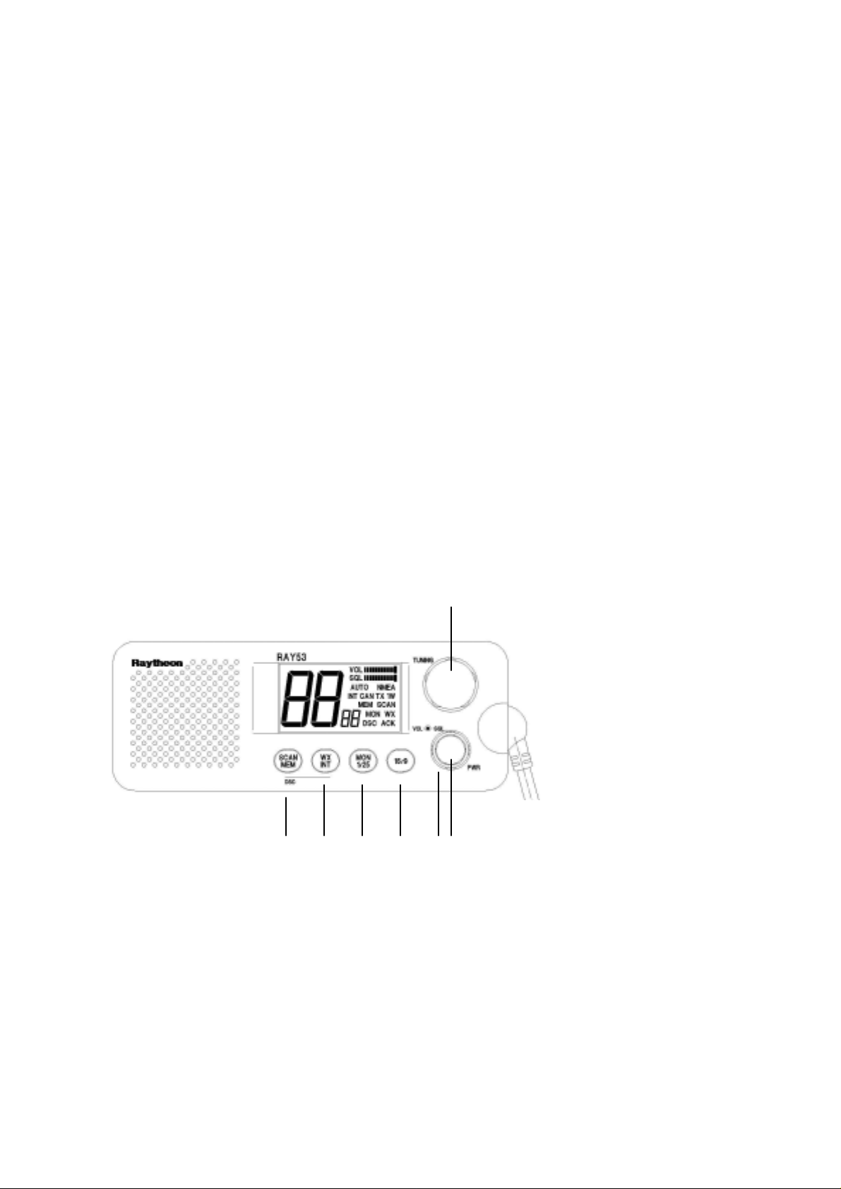
1.2 CONTROLS AND LCD DISPLAY
1)
4) 5) 6) 7) 2) 3)
Page 3
1.2.1 Controls
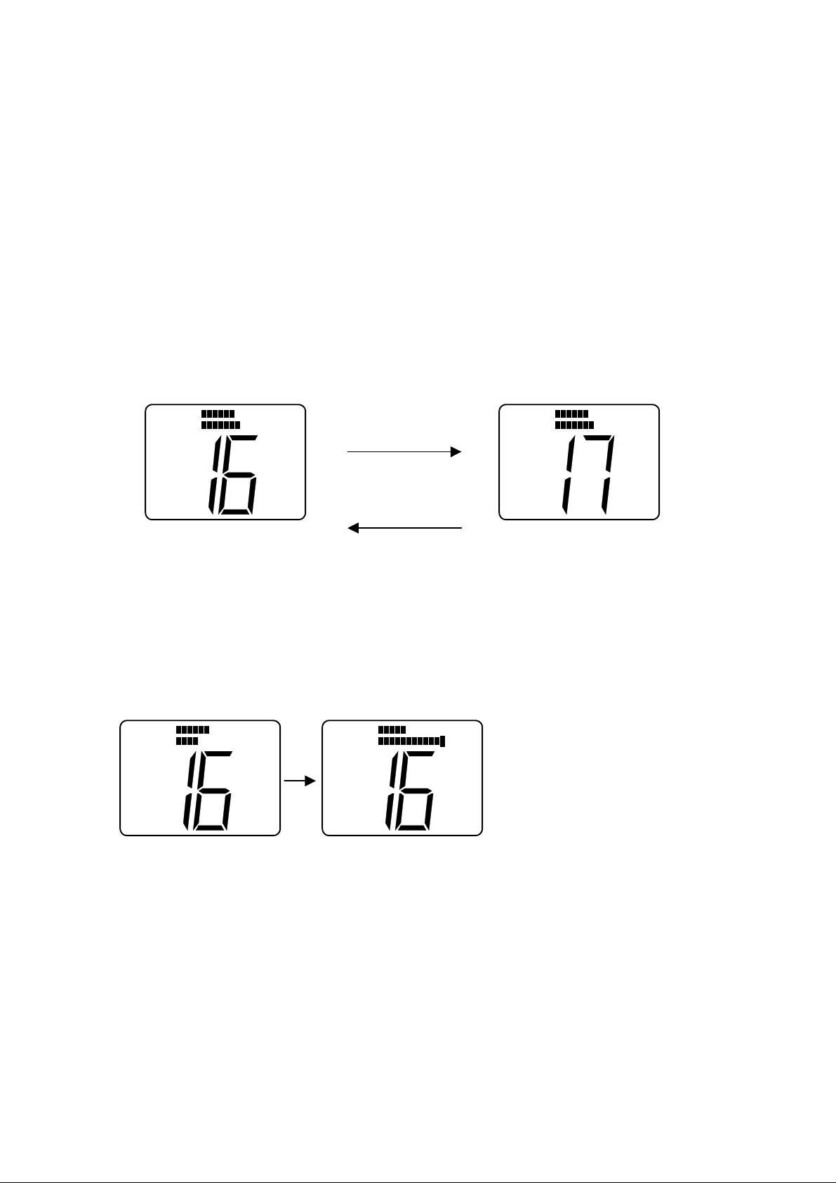
1) Channel Selecti on (Knob)
-. Turning to the right can increase the channel number and it can be
decreased by turning to the left.
-. When the Channel Selection Knob is rotated to the right at “88C H”, t he channel
number becomes “01CH”.
-. When the Channel Selection Knob is rotated to the left at “01CH”, the channel
number becomes “88CH”.
(UP)
SQL
NMEAVOL
SQL
NMEAVOL
Rotate clockwise
(DOWN)
Rotate counter clockwise
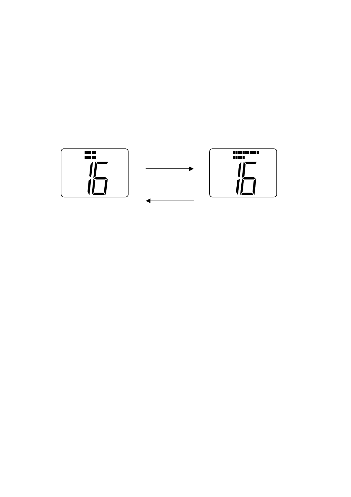
2) Squelch Knob
-. When Squelch knob is rota t ed, t he squelch level is adju st ed. If the knob is rotated
completely clockwise,all bars w ill illuminate.
SQL
NMEAVOL
SQL
NMEAVOL
Rotate
Clockwise
Page 4
3) V olume Knob
-. The volume knob controls the audio volume and is also switched to turn power on
and off. When the knob is rot at ed clockwise from the “OFF” pos ition,the power
becomes “Turned On”. Being rotated clockwise, t he audio volume will be
increased. Being rotated count erclockwise,the audio v ol ume will be decreased.
(Volume UP)
SQL
NMEAVOL
SQL
Rotate clockwise
(Volume DOWN)
Rotate counter clockwise
-. When the power is turned on, the receiv ing mode is in use after the follow ing
initial settin g .
Initial setting at power on.
Frequency mode--------: the frequency mode at power OFF
Channel --------: 16 CH (Working CH)
Priority CH --------: Priority CH at power OFF
Weather CH --------: Weather CH at power OFF
Transmitter Power---- : 25 Watt
NMEAVOL
-. When the power is turned on with pushing on SCAN/MEM key,all the memory
can be clear.
4) SCAN/MEM key
-. When SCAN/MEM key is pressed a nd released, Alarm 1 is heard and Scan
starts/stop. (To cancel the scan mode, press and release while rad io is scanning.
To start the scan mode, press and release while radio is not scann in g. )
-. If one or more channels are stored in memory, the radio will begin Memory Scan.
If no channels are stored in memory,the radio will begin All Scan.
Page 5

-. To begin All Scan while memory are being stored in, A ll Scan can be begun by
pressing once more during flash in g on t he LCD.
-. When SCAN/MEM key is continuin g t o be pressed for more than three
seconds, Alarm 1 is heard and Memory of the current channel can be
stored/canceled.(When the current channel is stored,the current cha nnel will be
canceled. When no other channe l is st ored, the current channel will be stored.
5) WX/INT key
-. When WX/INT key is pressed a nd released, Alarm 1 is heard and Working CH
/Weather CH are toggled each ot her.
-. When WX/INT key is continued to be pressed for more than 2 seconds, Alarm 1 is
heard and frequency selection mode(US,Internation al or Canadian) can be
changed. There are 3 types of frequencies selection modes,US,International and
Canadian. The frequencies selection mode is changed like USA--
Æ
CAN--ÆINT.
-. While the monitor operation is in use,Dual monitor and Triple monitor can be
changed.
6) MON/ 1/25 Key
-.When MON/ 1/25 is pressed and re leased, Alarm 1 is heard and Monitor operat i on
start.(Dual Monitor)
-. When MON/ 1/25 continues to be pressed for more than 2 seconds, Alar m 1 is
heard and Transmitter power can be changed. When transmitter power is 25W, it
can be 1 W. When transmitter power is 1 W, it can be 25 W.
7) 16/9 Key
-. When 16/9 key is pressed and released, Alarm 1 is heard and Channel can be
changed as follows.
The current channel is Working CH-------------- The current channel is Weather CH-------------- The current channel is Priority CH ---------------
Æ
Becomes Priority CH
Æ
Becomes Priority CH
Æ
Becomes Working CH
-. When 16/9 key continues to be pressed for more than 2 seconds, Alerm 1 is heard and
priority CH can be togg led. When the privat e channnel is 16CH,it can be changed to
9CH and when the priv at e channel is 9CH,it can be changed to 16CH.
Page 6

8) PTT Key(Microphone)
-.
When pressed,puts the radio into the transmit mode
If the current channel is Weather CH or the channel prohibitted from TX, Alerm 2 is
heard and PTT key cannot be used. If the PTT key is pressed continuously for over
five minutes,transmission is forcibly inhi bited and Alarm 2 is heard until the PTT key
is released.
9) UP key(Microp hone)
-.
The UP key is used to move the chann el numbers up(+1).
If the UP key is continuously pressed for over 0.5 seconds,the channel n umbers can be
continuously up every 100msec.
10)DOWN key(Microphone)
-. The DOWN key is used to mov e t he channel numbers down(+1)
If the DOWN key is continous ly pressed for over 0.5 seconds,the channel numbers
can be continueously down ev ery 100msec.
11) 16/9 key(Microphone)
-. When 16/9 key is pressed and released, Alarm 1 is heard and Channel can be
changed as follows.
The current channel is Working CH-------------- The current channel is Weather CH-------------- The current channel is Priority CH ---------------
Æ
Becomes Priority CH
Æ
Becomes Priority CH
Æ
Becomes Working CH
-. When 16/9 key continues to be press ed for more than 2 seconds in Priority CH mode,
Alerm 1 is heard and priority C H can be toggled. When the priv ate channnel is 16CH,it
can be changed to 9CH an d w hen the private channel is 9CH,it can be changed to
16CH.
12) DISTRESS key
-. DISTRESS key is use d t o send a DSC Distress Call when pressed and held for 4
seconds.
Page 7
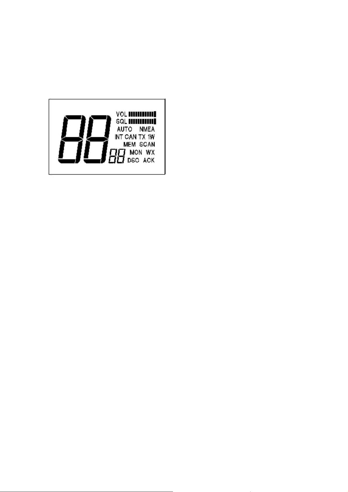
1.2.2 LCD Display
The items of LCD display on the Front panel are descr ibed as follows
1) DSC display:
2) WX display
Will be displayed when DSC mode is entered.
: Will be displayed when Weather CH is entered.
Will be displayed when Tri monitor mode is entered.
3) INT display
use. “INT” is not displayed when US or Canadian channels are
: Will be displayed when International ch annels are programmed for
programmed for use.
4) CAN display
: Will be displayed when Canad ian channels are programmed for use.
“CAN” is not displayed when US or Internat ional channels are
programmed for use.
5) MEM display
: Will be displayed when displayed CH is memory-registered.
Will blink at Scan Stand-by and be display ed at Memory Scan.
6) SCAN display
: Will be displayed at Sca n mode
Will blink at Scan at Scan mode and be displayed with “ME M” at
Memory Scan.
7) ACK display
: Will be displayed at DSC mode when the response to individual calls
are received after DSC call is transmitted.
8) MON display
: Will be displayed at Monitor mode
(Dual monitor or Triple monitor)
9) TX display
: Will be displayed when transmitter pow er is det ected at transmitter
mode.
Page 8

10) 1 W display
: Will be displayed when the transmitter circuits are providing 1 Watt
of power to the antenna. When the transmitter is su pplying 25 Wat t
to the antenna, “1 W” will be extinguished.
11)VOL, Bar
Graph display
: The Vol. bar graph shows the level of volume of the audio output
to the speaker.
The volume means to be larger when the dot of the bar graph
become increased to the right.
12) SQL,AUTO
Bar graph
display
: The Squelch bar graph shows the de pt h of squelch.
“AUTO” will be displayed when Auto-Squelch is activate.
The number of dot of SQL Bar graph will be increased when SQL
knob is turned to the right to make Squelch deeper.
(When SQL knob is furthermore turned to right from the
maximum squelch, the squelch becomes AUTO Squelch and
“AUTO” will be displayed.
13) NMEA display:
will be displayed at all of the modes while valid NMEA data is
being received.
When NMEA data is invalid or is not received,”NMEA” is
extinguished.
Applicable data: GLL,GGA,RMA,RMC,APA,APB
14) Channel display :
(Large)
display(Large) shows its situation.
15) Channel display
(Small)
Will display channel nu mb er in use.
When Own Ship’s MMSI ID is entered,etc,Channel
: Will display Priority CH number in use.
When Own Ship’s MMSI ID is entered,etc, Channel
display(Small) sh ows its situation.
Page 9

1.3 OPERATING PROCEDURES
1.3.1 Turning the Power O n
1) Rotate the VOLUME knob clockwise to turn t he radio on.
1.3.2 Setting the Volume
1) Rotate the VOLUME knob for the disired volume level.
1.3.3. Setting the Power Output
1) Simply press the “MON 1/25” key for two seconds to toggle bet w een 1 Watt output
and 25 Watt output. When “1 WATT” is d isp layed,the output power is 1 Watt.
If “1 WATT” is extinguished, 25w at t s is being output. The choice of p ower output is
dependent upon the distan ce of transmission and tran smitting conditions. I n cert ain
US harbors and on certain channe ls, the FCC requires the power to be limi t ed to
1 Watt. On these “required “ channels,the radio automatically selects 1 Watt power
output when the channel is selected.
1.3.4 Selecting the Channel
1) To select the appropriate channel, rotate CHANNEL SELECTION Knob clockwise /
counterclockwise or also press U P/ DOWN key of the microphone.
2) The channels which are not set on the frequency mod e are skipped .
3) When UP/DOWN key is continuously pressed for over 0.5 seconds,the channel is
continuously changed(+1 or – 1) every 100msec during pressing UP/DOWN key.
1.3.5 To select the frequency mode
1) The frequency mode(group) can be selected from US mode, International mo de and
Canadian Mode.
The frequency mode can be shown on the LC D as follows.
USA frequency mode--------------------------- CANADIAN frequency mode------------------
Æ
“INT” and “CAN” are eliminated
Æ
“CAN” is displayed and “INT” is
eliminated.
INTERNATIONAL frequency mode----------
Æ
“INT” is displayed and “CAN” is
eliminated.
Page 10

When WX/INT key is pressed and held for ov er 2 seconds, one frequency mode
can be changed to the other frequency mo de and Alerm 1 is heard.:
For example:
When USA mode is in use,it can be changed to CANADIAN mode by doing above
operation.
When Canadian mode, it can bew ch anged to International mode. When
International mode,it can be changed to USA mode. The last changed frequency
mode can be memorized.
When the power is turned on,the last memorized frequency mode can be
used.(Channel number is16C H at t hat time.)
1.3.6 To Transmit
1) Press the Push-To-Talk switch(PTT switc h) and speak into the microphone using a
clear normal voice.
2) If the current channel is Weather CH or the Tx prohibit ed channel, PTT switch c annot
be used and Audible beep sound 2 is heard.
3) RAY53 is designed to meet the new FCC Rules Part 80.203, which states,i f the PTT
switch is pressed continuously for over five minutes, t r ansmission is forcibly in hibited.
If this occurs,audible b eep sound 2 will be heard until the PTT switch is released.
1.3.7 To select a Weather Chan nel
1) Simply press the WX/INT,then use Channel Selection Knob or UP/DOWN key to
select the desired Weather Channel from 0 to 9. When this mode is selected,the
transmitter is always inhibited.
2) When the Weather CH is finished by pressing WX/INT key,the last used Weather CH
number is memorized
3) When the power is re-turned on,t he memorized Weather CH number can be
activate on the Weath er CH mode.
1.3.8 Priority Channel
1)When 16/9 is pressed and released, Alarm 1 is heard and Pri orit y Channel is in use then
Channel Display(Sma ll) shows “P” on the LCD.(“P” display means “Priority CH”.)
Page 11

2) When 16/9 key is pressed and rele ased again during “P” is diplayed, A lerm 1 is heard
and the channel will be returned to the privious Working CH. When the channel is
changed by UP/DOWN key during Priority CH is displayed, “P” display will be
eliminated and Workimg C H wil l be in use.
3) When 16/9 is continueously pressed for over 2 seconds, Alerm 1 is heard and Priority
channel can be changed either 16CH or 9CH.( When Priority CH is 16CH, it can b e
changed to 9CH and when Pr iority CH is 9CH,it can be changed to 16CH.)
1.3.8 Channel Memory
1) The RAY53 has the capability of memorizing all US,Internationa l and Canadian
Channels. The channels memorized will be scanned in the Me mory Scan mode.
2) Channel Memory: When SCAN/MEM key is pressed a nd held for over 3 seconds,the
audible beep sound 1 is heard and the selected current channel can
be put into memory.
When the displayed channel on the LCD is memor iz ed, “MEM” is
displayed on the LCD.
Memory Clear : To press and hold for 3 seconds w hen the memory channel is
stored, the audible beep sound 1 is heard and the channel c an be
cleared
When the displayed channel is not memorized,”MEM” is not
displayed on the LCD.
1.3.9 Scan Modes
The RAY53 is equipped with two types of scan options, All-scan and Memory Scan. How these
options are accessed is dependent upon whether there are any channels stored in memory.
1) All-Scan mode
If no channels are stored in me mory,when the SCAN/MEM key is pressed and
released, the audible beep sound 1 is heard and ”SCAN” will begin to flash on the LCD for
three seconds. If no other keys are pressed in these three seconds,the radio will begin
scanning all channels(exce pt weather chann els) as long as no signal is receiv ed. If a signal is
received,the scan will stop on the receiving channel. If the signal is lost for five seconds, the
Page 12

radio will resume scanning. While the radio is s cannin g ALL-Scan, ”SCAN” is disp layed on the
LCD.
To cancel the scan mode,press the SCAN/M EM key while the radio is scanning.
2) Memory Scan mode
If one or more channels are stored in me mory,when the SCAN/MEM key is pressed and
released, the audible beep sound 1 is heard and “SCAN” and “MEM” will begin to flash
simultaneously on the LCD for 3 seconds. If no other key is pressed in these three seconds,
the radio will begin scanning all channels currently in memory.(Begin Memory scanning) As
with All-Scan, If a signal is received,t he scan will stop on the receiving ch annel until the s ignal
is lost for five seconds, the radio w i ll resume scanning.
While the radio is scanning M emory Scan, “SCAN” and “MEM” are displayed on the LCD.
To cancel memory scan,press the SCAN/MEM key w hil e t he radio is scanning.
When SCAN/MEM key is pressed again during “MEM” flashing within these three
seconds, the audible beep soun d 1 is heard and “SCAN” will flash on t he LCD and the
radio will begin ALL Scan mode. “MEM” will disaprear from the LCD leaving only “SCAN”
flashing.
1.3.10 Monitor operations
1) The RAY53 is equiped with 2 types of monitor operations, Dua l Watch opeartion and
Tri Watch operation.
Working CH and Priorit y CH can be monitored altern at ely in Dual Watch operat ion.
Working CH, Priority CH and Weather CH can be monitore d by turns in Tri Watch
operation.
2)Dual Watch and Tri Watch can be changed each other by usin g WX/INT key.
When WX/INT key is pressed and released in the monitor mode, Alerm 1 is heard
and Dual Watch and Tri Watc h can be changed each other alter nat ely.
Page 13

WX
SQL
NMEAVOL
SQL
M O N
NMEAVOL
VOL
SQL
M O N
MON
WX
WX
Dual Monitor Tri Monitor
Dual Watch operation
-. “MON” is displayed on the LCD.
-. Working CH number is displayed at Channel Display ( Large) on the LCD.
-. Priority CH(16CH or 9CH ) number is displayed at Cha nnel Display(Small) on the
LCD.
. If the signal of Working CH i s detected, the Channel D isplay(Small) will be
extinguished and the monitor will stop tem por arily. Then the Re ceiver will be done for
NMEA
7 seconds.( Even if there is no carrier for these 7 seconds, the monitor will stop for 7
seconds.) After 7 seconds is passed,the rad io wi ll mo nitor Priority CH.
-. If the carrier of Private CH is detect ed , the Priority CH number is disp layed at the
Channel Display(Large) and the Channel Display (Small) will be extinguished and the
monitor will stop te mporarily.
Tri Watch operation
-. “MON” is displayed on the LCD.
-. Working CH number is displayed at Channel Display ( Large) on the LCD.
-. Priority CH(16CH or 9CH ) number is displayed at Cha nnel Display(Small) on the
LCD.
-. “WX” is displayed on the LCD
-. If the carrier of Working CH is detected, the Channel Displ ay(Small) will be
Page 14
extinguished and the monitor will stop temporarily. Then the R eceiver will be done
for 7 seconds.( Even if there is n o carrier for thse 7 seconds, the monitor will stop for 7
seconds.) After 7 seconds is pas sed, t he radio will monitor Priority CH.
-. If the carrier of Private CH is detect ed, the Priority CH number is disp layed at the
Channel Display(Large) and the Channel Display (Small) will be extinguished and the
monitor will stop te mporarily.
7 seconds has been passed after the carrier is eliminated, t he radio will monitor
Weather CH.
-. If the carrier or the alert of Weather CH is detected, t he monitor operation will stop
and Weather CH will become in use with “WX” flashing every 0.5 sec and Alerm 3 is
heard for 5 seconds.
The Variation by carrier detecti on during Monitor operation
Carrier Detection at Working CH
NMEAVOL
SQL
M O N
M O N
SQL
NMEAVOL
SQL
M O N
NMEAVOL
Carrier is detected 7 seconds is passed
at Working CH after the carrier is OFF
Carrier Detection at Priority CH
NMEAVOL
SQL
M O N
M O N
SQL
NMEAVOL
SQL
M O N
Carrier is detected 7 seconds is passed
at Priority CH after the carrier is OFF
NMEAVOL
Page 15

Carrier Detection at Weather CH (Alert is received)
VOL
SQL
M O N
NMEA
VOL
SQL
M O N
NMEA
M O N
VOL
SQL
NMEA
WX
WX
WX
Carrier is detected Alert is not detected
at Weather CH
VOL
SQL
WX
Alert is detected
"WX" flash
Exit Monitor mode
NMEA
1.3.11 The key opeartion durin g the monitor operation.
-. When PTT key is pressed,the monitor will stop and the transmission will be done at
the stopped channel. While detecting the carrier of Weather CH or detecting Weather
Alert, the transmission will be done at Workimg CH.
Page 16

VOL
SQL
M O N
WX
Press PTT key
NMEA
SQL
NMEAVOL
TX
at Priority CH
Priority CH is transmitted
SQL
TX
NMEAVOL
Press PTT key at Working CH
Press PTT key at Weather CH
Working CH is transmitted
-. When SCAN/MEM key , MON/ 1/ 25 key or UP/DOWN key is pressed, A lerm 1 is heard
and the monitor will stop and the n Workimg CH will be in use.
Stop monitor mode
Switch to
SQL
M O N
NMEAVOL
SQL
NMEAVOL
Working CH
Page 17

-. When 16/9 key is pressed, Alerm 1 is he ard and Scan oper at ion w ill stop an d then Prior ity CH
will be in use.
Stop monitor mode
Switch to
M O N
SQL
NMEAVOL
SQL
NMEAVOL
Priority CH
-. Even if the Channel Se lection knob is operated,there is no change.
1.3.12 The operation for Weather Alert detection(Alert Tone : 1050 Hz)
Alert detection checks the output power from Alert detection IC as following timing.
100msec 10msec 25msec
0 2 4 6 8 10 11 12 13 14 15 16 17 18
-. When the alert is ready to be detected(w hen t he carrier is detected), the detection
will start to be checked aft er 100msec.
-. The detection is checked 11 times per every 10msec and then the detection is
checked 8 times per every 25msec. If the a lert is det ected at all the checking poi nts,
it means that Weather Alert can be detected.
The detection are checked with ti ming changed during total 300msec.
-. If none of detection is detected bet w een 0 and 18 with the above timing, re-start at
first 100msec.
-. If the alerts are not detected at some o f the above timing between 0 and 18,the
following scanning will be done.
When alert tone is detected at Tri Watch monitor, “WX” display flashes every
sec and Alarm 3 is heard for 5 seconds.
Page 18

Alert tone is detected
"WX" flash and
VOL
SQL
M O N
NMEA
VOL
SQL
NMEA
Alarm 3 is heard
WX
WX
2. When alert tone is detected at Weather CH, “WX” display flashes every 0.5sec.
(Alarm 3 is not heard)
Alert tone is detected
VOL
SQL
NMEA
VOL
SQL
NMEA
"WX" is flashing
WX
WX
The operation by any keys after a lert det ect i on.
-. When either PTT key,SCAN/MEM key or MON/1/25 key is pressed, Alarm 2 is
heard to prohibit keys from using.
-. When WX/INT key, 16/9 key or UP/DOWN key is pressed, “WX” disp lay will be
eliminated and the key operation will be in use.
-. Even if the Channel Selection knob is operated,t here are no changes.
1.3.13 DSC (Digital Selective Calling)
The DSC mode enables you to contact or be contacted by another vessel digitally,without voice
communications. DSC can be us ed t o replac e the nor ma l routine o f ve rbally contactin g anoth er
vessel on CH16,then proceeding to a working channel for further communications. Your radio
must be set to CH70 to transmit or receive DSC ca lls. The three DSC call modes are d escribed in
the following section.
Page 19

1) Own Ship’s ID Entry(Own Ship’s MMSI Entry)
To operate the RAY53 in the DSC mode,Own Ship’s ID must be registered in advance. The
registration procedure is as follow s.
1. * If the former ID has been entered, Own Sh ip’s ID cannot be entered and Alarm 2 is
heard. There should be no MMSI number in t he unit when shipped.
It is necessary for re-enter Own ship’s ID to delete the former ID by Own Ship’s ID
Clear.
*If there is no former ID, Alarm 1 is heard and Own S hip’s ID can be entered.
2. To enter DSC setting mode, press and hold the SCAN/MEM and WX/INT keys
simultaneously for 2 seconds.
Æ
----
----
“DSC” is displayed, which mea n s t he unit is in DSC mode.
Æ
“MEM” is displayed, which means Own Ship’s MMSI can be entered in DSC
mode.
3. MMSI number can be put by the foll ow i ng operation
-. “0” is displayed at Channel Display(Large) on the LCD and “1” is displayed at
Channel Display(Sm al l) on t he LCD.
Channel Display(Large) is representative the MMSI number it self and Channel
Display(Small) is representative of the pos it ion in the 9 digit.
-. When the Channel Selection knob is rotated, Channel Display(Large) shows the
MMSI number is increased/decreased as “0” base.( 0 t o 9 can be selected)
-. MMSI number is selected by knob being rotated. When DSC key is pres sed,
the audible beep sound 1 is heard and the selected number c an be memorized.(“2” is
displayed at Channel Display(Smal l) on the LCD which means t hat 2
nd
(second) digit is
ready to be input. And the rest of the digits are entered in the same manner.
-. Once all of the digits have been entered, the unit will redisplay ID numbers every
1 second.
-. If the number was entered incorrectly, the customer perform the entry again by
pressing and releasing DS C key. At that time “0” is displayed at Channel
Display(Large) and “1” is displayed at Channel Display(Sma l l).
Page 20

-. If the number is entered correctly, the entered number becomes Own Ship’s
MMSI by pressing DSC key for 2 seconds and the audible beep sound 1 is heard,then
the DSC mode is exited and returned to Working CH.
4. Entry of number is done by Channel Selection knob. The number cannot be input by
UP/DOWN key on the Microphone.
The stored data can be memorized only by DSC key
The stored data cannot be memorized by the other key operation s and cannot be done
when the power is turned off on the way.
5. The way to CLEAR Own ship’s ID No.
To turn the unit on with pressing and holding SCAN/ MEM + 16/9 key simultane ously.
The audible beep sound 1 is heard and “CL” is displayed at Ch annel Display(Large).
2) Individual Ship’ Call”
1. “Individual Ship’s C al l” specifies other Ship’s Number and the channel number.
Unless Own Ship’s MMSI I D i s ent ered, Individual Ship’ s C all cannot be used.
2. When SCAN/MEM key and WX/INT key are simultaneously pressed and
released, Individua l Ship’s Call wi ll be in use.
Æ
---
“DSC” is displayed on the L C D which means the unit is in D SC mode.
Æ
---
Channel 70 is displayed at C hannel Display(Large)
(Programming for PLL data of 70CH.)
Æ
---
“In” is displayed at Channe l D isplay(Small) which means the unit is in
Individual Ship’s Call mo de.
3. When SCAN/MEM key (“DSC” key) is pressed and released, the audible beep sound 1 is
heard and the other ship’s Nu mber can be set.
-. “0” is displayed at Channel Disp lay(Large) on the LCD and “1” is displ ayed at
Channel Display(Small) on the LCD.
Page 21

Channel Display(Large) is representative of the MMSI number itself and Channel
Display(Small) is representative of the position in the 9 digit.
-. When the Channel Selection knob is rotated, Channel Display(Large) shows the
MMSI number is increased/decreased as “0” base.( 0 to 9 can b e selected)
-. MMSI number is selected by knob being rotated. When SCAN/M EM key(DSC key) is
pressed, the audible beep so und 1 is heard and the selected nu mb er can be
memorized.(“2” is displayed at Channel Display on the LCD, which means that 2
nd
(second) digit, is ready to be input . And the rest of the digits are entered in the same
manner .
-. Once all of the digits have been entered, t he unit will redisplay ID numbers
every 1 second.
-. If the number was entered incorrectly, the customer can perform the entry again by
pressing and releasing SCAN/M EM key(DSC key). At that time “0” is displayed at
Channel Display(Large) and “1” is d isplayed at Channel Display(Small).
4. Entry of number is done by Channel Selection knob. U P/DOWN key on the
Microphone does not enter the number.
5. If the number is entered correctly, the entered number becomes “Other Ship’s
Number” by pressing SCAN/M EM key(DSC key) for 2 seconds and the audible beep
sound 1 is heard.
The stored data can be memorized only by SCAN/MEM key( DSC key).
The stored data cannot be memor iz ed by the other key operations and can not be done
when the power is turned of f on the w ay.
6. After entry of “Other Ship’s number”, O t her Ship’s Channel Number is ready t o be
entered.
Æ
---
”--- ---“ is displayed at Channel Display ( Large) w hi ch means Channel number
is ready to be entered.
Æ
---
“W” is displayed at Channel Dis play(Small) which means t he working channel
is to be selected.
Page 22

6’ If the operator would like to resist or O t her ship’s MMSI No.only without att empt of
transmission, the last used(before reg istration of MMSI) CH will be disp layed by
pressing 16/9 key at this stage.
7. -. Working Channel can be selected by rotating Ch annel Selection knob.
-. When SCAN/MEM key(“DSC” key) is pressed and released, the audible beep sou nd
is heard and the selected number can be memorized as Working Channel number.
8. If the operator would like to resistor Other ship’s MMSI No.only without attempt of
transmission, the last used(before registration of MMSI) CH will be displayed by pressing
16/9 key at
9. After entry of “Channel number”, “Individual Ship’s Call” is ready to transmit.
Æ
----
----
“TX” is flashing on the display(I nst ruct ion t o be ready to transmit)
Æ
Channel 70 is displayed at Channel Display(Large)
(Programming for PLL data of 70CH.)
Æ
----
“In” is displayed at Channel Display(Small) (Instruction for Ind ividual Ship’s
Call)
-. While “TX” is flashing, I ndividual Ship’s Call can transmit at 70CH by pressing
PTT key.
-. After transmission, when an acknow ledgement from the target ship is
received, the audible beep sound is heard and “ACK” is displayed on the LCD.
-. When 2 seconds is passed afte r r eceipt of acknowledge, the unit will switch to
selected Channel number and “D S C” mode will be exited.
When DSC mode is exited,”DSC” an d “A CK” will be eliminated.
Channel Display(Large) disp lays the selected Channel number.
Channel Display(Small) is eliminat ed.
-. If an acknowledge from the target ship is not received, “Individual Ship’s Call” at
70CH is still remaining in use.
(“Individual Ship’s Call” can transmit again by pressing PTT key)
Page 23

10. The way to CLEAR Other ship’s MMSI No.
There are two ways to clear Other Sh ip’s MMSI No.
1) To turn the unit on with pressing and holding SCAN/ MEM key simultaneously.
Alarm 1 is heard and “CL” is display ed at Channel Display( Large).
Or
2) To turn the radio on with pressing and holding SCAN/M E M key and 16/9 key
Simultaneously. Alarm 1 is heard and “CL” is displayed at Channel Display(Large).
(Own Ship’s ID No. is also CLEAR by doing this operation.)
3) Other ship’s MMSI previously entered.
When the other ship MMSI number has been entered,the operator does not have to
register the other ship’s MMSI number by doing the following procedure.
1.
Press SCAN/MEM key and WX/INT key simultaneo usly
2.
Then “MEM”, “DSC”, “70” (Large channel display), “In”(Small channel display) are displayed
on LCD.
-“MEM” means that the other ship’s MMSI number has been registered.
-.”DSC” means that the unit is in DSC mode.
-.”In” means that the unit is in DSC mode.
3.
Press and release DSC key.
4.
“MEM”,”DSC” “0”(Large channel display ) and “1”( S mall ch annel d isplay ) are di splay ed on the
LCD.
5.
Press and release MON key if y ou w ould like to check the MMSI number.
6.
The MMSI number of each digit is di splayed every 1 sec from 1st digit t o 9t h digit.
MMSI number itself is displayed on the Large Channe l Display.
The number of digit is displayed on the Small Cha nnel Display.
7.
After all MMSI number(total 9 d igits) are displayed, to press DSC key for 2 seco nd,
the LCD displays “DSC”, “ --- ---“,(Large Channel Display) and “w”(Small Channel
Display) which me ans t he unit is ready and wait i ng for input of Calling C H .
Page 24

5’
Press and release WX/INT key if you do not have to check the MMSI number ag ain ,
6’
the LCD displays “DSC”, “ --- ---“,(Large Channel Display) and “w”(Small Channel
Display) which means the u nit is ready and waiting for input of Calling CH .
8.
(If you would like to enter the different Other Ship’s MMSI numb er manually),
1. To rotate channel selection knob from the stage of the above 4(“MEM”,”DSC”,”0” and
“1”) ,then the different other ship’s MMSI number can be set. The LCD displays “DSC” ,
“3”(Large Channel display ) and “1” (Sma ll Ch ann el di splay ) w hich means t hat the nu mber o f
st
1
digit is 3.
2. To press and rel ease DSC key for confirmati on,Alerm 1 is heard and the MMSI nu mber of 2
digit will be ready to be input. “MEM”, “DSC”,”0”(Large Channel Display) and “2”(Small
Channel display) are displayed on the LCD. To rotate Channel Selection Knob,the MMSI
number of 2
nd
digit is selected.
3. The rest of the digits are entered in the same manner.
4. Once all of the digits have been entered,the unit re-display MMSI Number every 1 sec from
st
1
digit to 9th digit. When the operator confirmed MMSI number, “DSC”
“--- ---“ and “w” are displayed on the LCD by pressing and holding DSC key for 2
nd
seconds.
If the operator would like to double check the MMSI number again or to change the MMSI
number , t he LC D displays “MEM”,”DSC”,”0” and “1” by pressing a nd rel easing DSC key.
4) Receiving Indiv i dual Ship’s Call Response
1. The receivable Channel is only 70CH. It can be done even in working CH, Monitor
mode and Scan mode.
2. When the unit receive t he signal, the unit will become automatically “DS C” mode.
If the received signal is for the unit itself,the unit wi ll respond the signal.
If the received signal is not for the unit itself, the unit will not respond and Monitor
Mode or Scan mode will continue to be in use.
3. The operation when the rec eived signal is for the unit it self.
When the unit receives “Individual Ship’s Cal l” at 70C H, Alarm tone will sound.
Æ
----
“DSC” is displayed which means the unit is in DSC mode.
Page 25

----Æ Channel Display(Large) di splays 70CH.
Æ
----
“In” is flashing at Channel Display(Small) which means the unit is ready to
receive Individual Ship’s Call.
Æ
----
“TX” is flashing, which means the unit is ready to receive Individual Ship’s Call.
4. To transmit the response by pressi ng PTT key.
After transmission,t he unit will switch to instruct ed Channel number and DSC
mode will be exited.
Æ
----
----
----
When DSC mode is exited, “DS C” i s eliminated.
Æ
Channel Display(Large) di splay the selected Channe l number.
Æ
Channel Display(Smal l) is e li m i nated.
5. The transmitter/receiver can be done at the selected channel number.
5) “All Ship’s Call”
1. “All Ship’s Call” does not specify the other ship.
“All Ship’s Call is general call to any ship to initiate contact on channel 1 6 .
Unless “Own Ship’s ID” is entered, ”All Ship’s Call” cannot be done.
2. When SCAN/MEM key and WX/INT key are simultan eously pressed and
released, “All Ship’s Call” will be in use.
Æ
----
----
“DSC” is displayed on the LC D w hich means the unit is in DS C mode.
Æ
Channel 70 is displayed at C h annel Display(Large)
(Programming for PLL data of 70CH.)
Æ
----
“In” is displayed at Channel Display(Small) which mea ns t he unit is in
Individual Ship’s Call mode.
3. “All Ship’s Call” c an be selected by rotating Channel Selection Kn ob.
Channel Display(Small) displays “AS”.
Whether “Individu al Ship’s Call” or “ All Ship’s Call” can be selected by Channel
Selection Knob.
Page 26

When “Individual Ship ’s Call” is select ed, Channel Dis play(Small) displays “In”.
When “All Ship’s Cal l” is selected, Chan nel Display(Sma ll) displays “AS” .
5. After selection of All Ship’s Call”,when SCAN/M EM key(“DSC” key) is pr essed,
the audible beep sound 1 is heard and the unit is ready to tr ansmit “All Ship’s Call”
Æ
----
----
----
“TX” is flashing on the LCD which means that T r ansmission is ready.
Æ
Channel 70 is displayed at Channel Display(Large).
Æ
“AS” is displayed at Channel Display(Small) wh i c h means that the unit is in
All ship’s Call mode.
6. While “TX” is flashing, All Ship’s Call can transmit at 70CH by pressing
and releasing PTT key. Transmitter output power is li mited to 1W.
7. After transmission,t he unit will switch to 16CH of Working CH and DSC mode will
be exited.
When DSC mode is exited, ”DSC” wil l be e li m inated.
Channel Display(Large) disp lays 16CH of Working CH..
Channel Display(Small) is eliminat ed.
(“Individual Ship’s Call” can transmit again by pressing PTT key)
5) Receiving All Shi p’ s Cal l
The receivable Channel is only 70CH. It can be done even in working CH, Monit or
mode and Scan mode.
When the unit receive the si gnal, the unit will become aut omatically “DSC” mode
1. When the unit receives “All Ship’s Call” at 70CH, Al arm tone will sound.
Æ
----
----
“DSC” is displayed which means the unit is in DSC mode.
Æ
Channel Display(Large) displays 70CH.
Page 27

----Æ “As” is flashing at Channel Display(Small) which means t he unit i s ready to
receive All Ship’s Call.
2. After the unit received “All Ship’s Call”, when SCAN/MEM key(“DSC” key) is
pressed, the audible beep sound 1 is heard and the unit will switch to the 16CH of
Working CH and then “DSC” mod e w il l be e xit ed.
Æ
----
----
----
When “DSC” mode is exited, “DSC” is eliminated from the LCD.
Æ
Channel display(Larg e) displays 16CH of Working CH.
Æ
Channel Display(Smal l) is e li m i nated.
6) “ Distress Call”
The “Distress Call” is to be initiated by pressing and holding the “DISTRE SS” key
on the rear of the microphone for 4 seconds.The Distress call has highest priority of
all the operations.
Unless Own Ship’s MMSI I D is entered, Distress Call is not av ailable.
1. When Distress key is continuously pressed, “Distress Call” can start to operate.
Æ
----
----
“DSC” is displayed w hich means the un it is in DSC mode.
Æ
Channel Display(Large) dis pl a ys Counts down time(4,3,2, 1).
Counts down will be shown every 1 second on Channel Display(Large)
Æ
----
“d” is displayed at Channel Disp lay(Small)
2. “Distress” key has to be pressed co nt inuously for over 4 seconds.
While Distress key is being pressed, Channel Display(Large) is showing Count
down times like 4
Æ3Æ2Æ
1.
If “Distress” key is released on the way before 4 seconds, “Distress C all”
operation will be cancelle d.
3. After Count down is finish ed, ”D ist r ess Call” can start to be trans mitted.
Æ
----
----
Channel Display(Large) di splays 70CH.
Æ
“d ” is displayed at Channel D isplay(Small) which means the unit is in
Distress Call mode.
Page 28

----Æ Distress signal can be autom at ically transmitted.( “TX” is displayed on the
LCD during transmitting.)
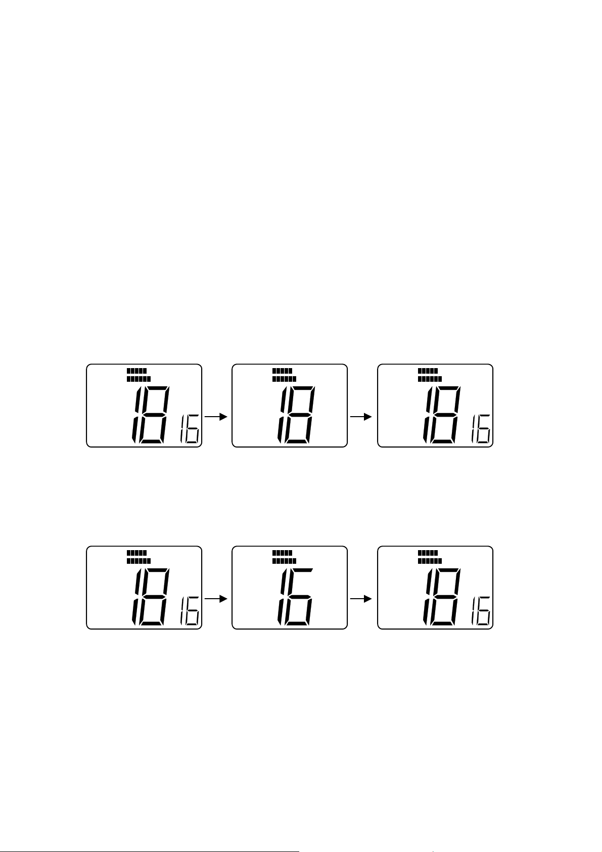
4. After transmitting Distress sig nal, the unit will wait for an acknowledgement from
the other ship.
----
----
Æ
Channel Display(Large) displays 70CH.
Æ
Channel Display(Smal l) displays “16” which means the channel after
receipt of an acknowledgement will be 16CH.
----
Æ
“TX” will be eliminated.
5. If the unit does not receive any acknowledgement from the ot her ships for Distress
Call even after Distress Call w as t r ansmitted, Distress signal can be
transmitted automatically randomly every 3.5 – 4 sec until rec eiving
acknowledgement from the oth ers.
When the acknowledgement is received,the automatic tr ansmission will not be
necessary.
6. Once an acknowledgement i s received from the other ship, Alerm tone will sound
and “Distress Call” mode w i ll be exited and the unit a ut omatically select 16CH.
Æ
----
”ACK” is displayed by receiv ing acknowledgement. (“AC K” w ill be eliminated
after 16CH is selected.)
Æ
----
”DSC” is eliminated.
Æ
----
----
Channel Display(Large) di splays 16CH of Worki ng C H.
Æ
Channel Display(Smal l) is e li m i nated.
7) Receiving “Distress Call”
The receivable Channel is only 70CH. It can be done ev en in working CH, Monitor
mode and Scan mode.
When the unit receive t he signal, the unit will become automatically “DSC” mode
(1)When the unit receives “Dist r ess Call” at 70CH.
Æ
----
“DSC” is displayed which means the unit is in DSC mode.
Æ
----
Channel Display(Large) displays 70CH.
Page 29

----Æ “d ” is flashing at Channel Display(Small) which means the un it is ready to
receive Distress Call.
After the unit received “Distress Call”, when “DSC” key is pressed and released,
Alarm 1 is heard and the unit w il l sw it ch t o the 16CH of Worki ng C H and then
“DSC” mode will be exited.
Æ
---
When “DSC” mode is exited, “DSC” is e lim inated from the LCD.
Æ
---
Channel Display(Sma ll) is eliminated3. DSC Watch mode can be a ctivate by doing following
operat.
8) DSC WATCH Mode/ON OFF operation
1. DSC WATCH operat ion is defined that the radio is searching for CH70(DSC C hannel) in
Receiving Working Ch annel , Scan Operation mode, and Monitor Operation mode.
2. DSC Watch operation can be selected with ON/O FF by panel operation. DSC WATCH
should be OFF when the unit is ex-f act oried.
1) Press and hold SCAN/MEM key and WX/INT key simultan eously for 2 seconds.
2) “DSC” , “70” (Large CH display) and ‘In”(Small CH disp lay) are display ed on the LCD. The
unit is in the selection mode for Individual Ship’s Call.
3) Rotate Channel Selection Knob to the right .
4) “DSC” , “70”(Large CH display) and “As”(Smal l CH d isp lay) are displayed on the
LCD. The unit is in the selec tion mode for All Ship’s Call.
5) Rotate Channel Selection Knob to the right .
6) “DSC”, “70”(Large CH display) , and “0F”(S mal l C H d isp lay) are displayed on the
LCD. At this stage, DSC Watch mode can be s el ected. “0F” on the Small CH
display means that DSC Watch is OFF.
Further to rotate CH selection Knob to the right,the unit repeat to be displayed from
the above 2) . The display will be don e as 6)Æ 2) Æ 4) Æ 6).
Page 30

To rotate Channel Selection Knob to the left, the unit will be displayed back to the
Above 4). The display will be d one as 6) Æ 4) Æ 2) Æ 6).
7) By pressing SCAN/MEM key, DSC Watch mode can b e sel ect ed either ON or OFF.
8) To press SCAN/MEM key and WX/INT key simultanously, the unit return to the last
Used display before the abov e 1) display.
9) When Power is re-act ivate on, the unit will start in the mode last used.( O n or OFF).
Page 31

2.
SPECIFICATIONS
Transmitter
Channels All available US,International and Canada VH F Marine band
Frequency Stability +/- 10PPM(+/- 0.001%)
(-20° C
to+50° C)
Frequency Range 156.025 to 157.425MHz
Channel Spacing 25 kHz Increments
Power Output 25 Watts switchable to 1 Watt into 50 Ohms at 13.6 VDC
Modulation Frequency modulated 16F3
(+/-4.5kHz at 1000Hz)
Modulation Audio Response Shall not vary +1/-3 dB fro m tr ue 6 dB pre-emphasis from 300
to 2500Hz, reference 1000Hz. Audio frequencies 3-20 kHz
shall be attenuated(at 1 kHz by 60 log f/3 dB. Above 20kHz
by 50dB)
FM Hum & Noise level Less than –40dB below audio
Audio Distortion Less than 10% at 1kHz for 3kHz deviation
Spurious & Homonic Attenuated at least 43+10log Po(be low rat d radiated carrier
Emissions power) per FCC Rules Part 2 & 80
Antenna Impedance 50 Ohm
Transmitter Protection Shall survive open or short circuit of anttena system w ithout
damage(10 min.test)
Page 32

Receiver
Channels All available US,International,Canada VHF Marine Band
Frequency Range 156.025 to 163.275 MHz in 25 kHz increments
Frequency Stability +/- 10 PPM(+/- 0. 001%) from -20
°Cto+50°C
Usable Sens itivity 0.3µV for 12dB(SINA D)
Squelch Sensitivity 0.2µV or better
Threshold
1.0µ full squelch
Adjacent CH Rejection 70dB
Spurious Image Re ject ion 70dB
Intermodulation Rejection 70dB
Audio Output 2 Watt or more at 10% or less distortion into 8 Ohm
load(INTERNAL)
Hum & Noise in Aud io Less than –40dB
Operating Requirement
Input Voltage 13.6 VDC +/- 15%(11.6 to 15.6 V DC)
Current Required Less than 5.8 amp at 25 Watts
Transmit Less than 1.5 amp at 1 Watt
Operating Temperature -20 °C to +50°C
Page 33

Duty Cycle Continuous, 80% receive, 20% transmit
°
(max 10 min, @25
C
)
Humidity 100% at 50°C for 8 hours
Radio Dimen s ions
Height 55 mm(2.17 inches)
Width 145mm(5.7 inches)
Depth 160mm(6.3 inches)
Weight Approx. 868g
Page 34

3. TECHNICAL DESCRIPTION
10.1 General
The RAY53 can be considered as consisting of two major sections.
-. The control section(consi sting of the front panel controls , LCD display,and
CPU
-. The transmitter/Receiver/PLL section.
10.2 The Control Section
.
The heart of the control section is the CPU,which is IC201 loc a t ed on the
CNTL PCB. The CPU cont rols all of the following items:
-. Controls the Squelch circuit by detecting a busy signal from the 2
nd
circuit IC3 on the RF PCB.
-. Generates a beep tone when a key is activ at ed on t he keyboard.
-. Mutes the transmitter modulation circuit w hen receiving.
-. Controls the output power of the trans mitt er H igh/Low .
IF
-. Controls the dividing ratio N of the PLL circuit.
-. Switches On/Off the transmitter power.
-. Mutes AF audio.
-. Detects a weather alert signal(when in Mo nit or Mode)
-. Controls the LCD display.
3. 3 The transmitter/Receiver/PLL Se cti ons
In reading through the following circuit descriptions, it may be he lpful to
refer to Block Diagram of the TX/RX/PLL circuits.
10.3 1. PLL(Phase Lock Loop) Circuit
PLL circuit of this radio is PLL IC(IC2) and is composed of VCO circuit which is for
Transmitt er and for Receiver independently. PLL IC(IC2)
generates
the setting frequency
based on the control data of CP U(IC201).
The reference oscillating frequency of the PLL circuit is 21.25MHz and is consisting of
crystal resonator X1 and I C2. Th is os ci llatin g fre quen cy 21.25M Hz is div ided i nto 1/850 to
Page 35

make 25KHz-reference frequency.
Transmit frequency is generated on the Inductor and Capacitor circuit with connected to
IC2 pin 4,5.
The frequency control voltage, which is output from IC2 pin 7, will be input into Variable
Capacitance Diode(D6) on I nductor and Capacitor circuit.
The receiver local frequency is generated on the Inductor and Capacitance circuit with
connected to IC2 pin 20, 21.
The frequency control voltage, which is output from IC2 pin 18, will be input into Variable
Capacitance Diode(D 5) composed on
The oscillating frequency 21.25MHz which is output from IC2 pin 11 will be used for the
second local frequency of Receiver and it will be input into IF IC(IC2) pin 1.
10.4 Transmitting Circuit Operation
3.4.1 Microphone Amplifier Circuit:
Voice signal from the mocrophone goes through pre-emp hasis circuit consisting of
C147 ,R104 and is amplified in MIC AMP IC8(A).
Pre-emphasis can be output by Diod e (D 10). The level of the signal is li mit ed by D7
and adjusted in the VR4.
Limiter output is amplified by I C8(B), t hen it goes through the active 4-stage L PF
consisting of IC8(C) and IC8(D). 4-stage LPF output goes into Variable Capacitance
Diode(D7) and then it makes Frequency modulat ion.
3.4.2 Transmit Freq uency Power Amplifier Circuit
RF signal from the PLL IC(IC2) pin 1 g oes t hrough the 10dB attenuator cons ist ing of
R37,R38,R39 and will be amplified by Q11. Output from Q11 will amplify drive power
necessary for the Q4 and Q3. power module(IC5) w i ll be amplified and the RF signal
will be output to the antenna sw it ching circuit. 4-stage L PF consisting of L21 and
L1-L3 is used to improve the level of Transm ission Spurious Emiss ion. RF output
from the power module(IC5) can be changed by changing the voltage of IC5 pi n2.
Page 36

3.4.3 APC Circuit
Diode D4 is monitoring a part of the power module’s(IC5) output. The monitoring
signal will be output to IC5 via switching transistor Q8 and display the “TX ON” and
the LCD.
The output voltage from IC5 controls the RF power to keep th e R F out put at a
constant level.
3.4.4 DSC Signal Treatment
In DSC mode at CH70,a sequence signal from CPU is input to MODEM IC(IC11) and
converted to an analog signal. As a MO DEM TX signal,this signal switches the analog
switch(Q20) from microphone input position to DSC position. Then DSC signal is sent
out to the transmitter microphone amplif ier.
If NMEA information are input to P501 conne ct or t hrough GPS or other devices
connected to it,these information are taken into CPU through photo-coupler of Q22
and can be transmitted with DSC t o provide information such as posit ion a nd time.
3.5 RECEIVER CIRCUIT
3.5.1 Antenna Switching Circuit
A signal received at the antenna connect or J501 goes to high frequency amplifier circuit via
4-stage low pass filter consisting o f co ils L1-L3 and L21.
3.5.2 High Frequency Amplifier Cir c ui t
RF signal goes to the 1
st
mixer circuit through 2-stage B PF(consisting of co il L5,6) and will be
high frequency amplifie d by Q 1 and t hen 3-st age B PF(c onsist ing o f L8, L10, and T3) . The 1
image spurious freque ncy will be reject ed to the adequate leve l in the 5-stage BPF inside the
high frequency amplifier circuit.
3.5.3 1
st
Intermediate Frequency Ampli f ier Circuit.
A double balanced mixer(DBM) o f IC1 is used for 1
st
mixer of Receiver.
RF signal from RF Am plifier circuit input to IC1 pin 6. Receiv er local frequency input from PLL
IC(IC2) pin 20 to IC1 pin3 and then converts the frequency.
The converted 1
st
IF signal(the frequency of 1st IF is 21.7MHz) goes through 1-stage crystal
filter(F1) and is amplified in transi st or(Q 2)
st
Page 37

3.5.4 2nd Intermediate Frequency Circuit
st
The 1
IF signal is added to IC3 and converted to 2nd IF signal. The 2nd IF signal goes
through F2 and amplified in the IC3 and then through discriminator CD1 and the
demodulated AF signal is out put from IC3.
3.5.5 Low Frequency Circuit
The AF signal demodulated in the IC3 goes through the de-emphasis circuit consisting of
operational amplifier IC4(A) and R127 and C45. A 3 stage active HPF consisting of
IC4(B) ,C48,C49 C50,R23,R24 and R25 is used to reject AF signal below 300Hz. The AF
signal from the 3-stage HPF goes through AF Volume VR301 and is input to the speaker
amplifier circuit IC9.
3.5.6 Audio Muting Circuit
The Q18 to mute the audio is contro lled by input of squelch’s B USY signal and the
mute output of the CPU(IC201).
3.5.7 WX Alert Detection
The tone selector IC10 detects the 1 050Hz alert tine if it is contai ned i n the
re-modulated AF and WX alert tone w il l be o ut put from the speaker.
3.5.8 DSC Signal Treatment
If the re-modulated signal arriving is a DSC signal, it is input to MODEM IC(IC11) as an RX
MODEM signal, and conv erted to digit al signal. Undergo ing the t reatment in the CPU c ircuit,
this digital signal ch anges the operation state to DSC mode.
Page 38

4. ALIGNMENT for RAY53
4.1 PLL Adjustment(Receiver)
1.1 Connect the power supply(13.6V, 10) to the power line.
1.2 Set the radio on CH16(156.800MHz) and set it t o Receiver mode.
1.3 Connect the reed terminal of a digital voltmeter or high impedance tester to Test
point(TP2) on RF PCB and set it to DC voltage range.
1.4 Adjust variable coil (T1) in the RF PCB( in the VCO shie ld case) an d set t he DC v oltage
to 1.3V+/-0.1V.
4.2 PLL Adjustment(Transmitter)
Connect the power supply (13. 6V,10A) to the power line.
Connect RF Power Meter(40W 50 ohm, 150-200MHz) to antenna connector.
Set the radio on CH16(156.800MHz) and set it to T ransmitter mode.
Connect the reed terminal of a digital voltmeter or high impedance tester to Test point(TP3)
on RF PCB and set it to DC v oltage range.
Adjust variable coil (T2) in the RF PCB(in the VCO shield case) and set the DC voltage to
2.0V+/-0.1V.
4.3. Frequency Adjustment(Transmitter)
4.3.1 Connect the power supp ly (13.6V,10A) to the power line.
4.3.2 Connect RF Power Meter(4 0W 50 ohm, 150-200MHz) to ant enna connector.
Use Coupler in order to divide the transmitter output pow er and then connect to
frequency counter.
4.3.3 Set the radio on CH16(156.800MHz) and set it to T ransmitter mode.
4.3.4 Adjust Trimmer Capacitor(TC1) in the RF PCB(in the VCO shield case) and set the
Frequency Counter to 156800.000Hz+/-100Hz.
4.4 Modulation Adjustment(Transmitter)
4.4.1 Connect the power supp ly (13.6V,10A) to the power line.
4.4.2 Connect RF Power Meter(40 W 50 ohm, 150-200MHz) to antenna connect or. Use
Coupler in order to divide the transmitter output power and then connects to FM
Page 39

linear detector.
4.3.3 Connect the audio oscillator and PTT test Assy t o Connector (J203) No.1 pin in
CNTL PCB. Set the audio oscill at or t o –18dBm and set the frequency to 1KHz
And then set it to transmitter mode.
4.4.4 Adjust Variable Resistor(VR4) in the RF PCB to set the deviat ion displayed on FM
linear detector to 4.2kHz+/-0.1kHz .
4.4.5 Set the audio oscillator to –38dBm and set the frequency to 1kHz. Confirm that the
deviation on FM linear det ect or should be 3.0kHz+/-0.5kHz.
4.5 Output Power Adjustment(Transmitter)
4.5.1 Connect the power supply (13.6V 10A) to the power line.and connect Power
Meter(40W, 50 ohm, 150-200MHz) to antenna connector.
4.5.2 Set the radio on CH 16(156.800MHz) and to be transmitter mod e at Low power
mode.
4.5.3 Adjust the output power to 1.0W+/-0.1W by Variable Resistor (V R 2) on t he RF PCB.
4.5.4 Change the transmitter output selector Switch int o Hi Power mode.
4.5.5 Adjust the output power to 2.5W +/-1W by Variable Resistor(VR3) on the R F PCB.
4.6 RF Sensitivity Adjustment(Receiver)
4.6.1 Connect a RF signal generator to the antenna con nect or and a SINAD meter to
the External speaker line.
4.6.2 Select the Weather Channel .
4.6.3 Set RF generator as follows:
Frequency : 163.275 MHz.
Modulation: 1.0 kHz
Deviation : 3.0kHz
4.6.4 Adjust T3 on RF board and make the best of SINAD sensitivity
Page 40

5. ELECTRICAL CONNECTIONS
5.1 DC Power, External Spe aker Connections and NMEA I nput
The 6 feet long power cable assembly cons ist s of the DC power cable and the
external speaker cable. The DC power ca bl e is composed of RED(+) and
BLACK(-) wires, and the external speaker cable has YELLOW(+) and
GREEN THICK(-) wires and NMEA Input has BLUE(+) and PURPLE(-). The
RED(+) wire with an in-line fuse(10 amps.) and the BLACK(-) wire of the 6 pin
connector cable are used for connecting the RAY53 to the ship’s 13.6 VDC power
system.
In most cases this length should be adequate enough to reach the DC p o w er
source.
If additional wire length is required,the cable can be extended by adding more
cable as necessary. However,for power cable runs longer than 15 feet,larger
wire diameter size should be used to prevent voltage line loss.
Your RAY53 radio should be conn ect ed t o t he nearest primary source of
ship’s DC power. A typical source may be a circuit breaker on the power
panel or a fuse block near the unit. When connecting to either of these
sources, the circuit breaker or other in-line fuse should be rated at 10 amps.
It is recommended that lugs be used to connect the power cable to the DC
supply and the lug connections should be both crimped and soldered. This is
very important in order to insure adequate currect draw to the equipment.
intermittent operation may result if an insufficient connection is made to the
power source. the connection terminal sho uld be clean, with no sigh of
corrosion.
The RED(+) wire is connected to the positive terminal of the power source or
battery . The BLACK(-) wire is connected to the negative(ground) of the power
source or battery. Should the power connect i ons be inadvertently reversed,t he
Page 41

10 amp.in-line fuse located in the R ED(+) wire will open. Check the input
power leads for correct polarity with a VOM(volt / ohm met er), reconnect the
leads observing correct polarity,and replace the fuse. Use the same rate and
type fuse.
-The RAY 53 accepts NMEA 0183 data from a GPS or Loran navigator to prov ide
Lat/Lon position information th at is t r ansmit during DSC Distress Call mode. The
NMEA sentences that could provide pos itio nal data,by order of priority are:
GGA.RMC,RMA,and GLL.
5.2 Antenna Connections
The coaxial cable to your VHF antenna is intended to be connected to the antenna jack
on the rear panel using a PL259 VHF type connector. The antenna cable may be cut to
the required length at installation. If a longer cable length is required, RG-58 50 ohm
coaxial cable or equiva lent cable may be used for runs up to a maximu m of 50 feet. If t he
distance required is even greater,then we recommend using low loss RG-213 or
equivalent cable for the ent ire run in order to avoid excessiv e losses in power output.
If the antenna RF connector is li kely to be exposed to the marine environment, a
protective coating of grease(similar to Dow Corning DC-4) can be applied to the
connetor before connecting it to t he radio. A ny other extens ion s or adapt ers in the c ab le
run should also be protected by silicon grease and then wrapped with a waterproofing
tape.
5.3 Antenna Mouting Suggestions
The best radio in the world is useless without a good ant enna location. Mounting t he VHF
antenna properly is very important because it will direct ly affect the performance of your
VHF radio. A standard VHF antenna which is designed to use aboard boats should be
used.
-. Since VHF transmission are essentially Line-o f-Sight,mount the antenna at t he
highest possible location on the vessel and free of obstruction in order to
Page 42

obtain maximum range.
-. Use an antenna with highest possible gain characteristics.
-. If you must extend the length of the coaxial cable between the a nt enna and the
Radio, use a coaxial cable designed for the least amount of power loss over
the entire cable length.
-. Keep the coaxial cable betw een t he radio and antenna as short as possible.
5.4 Grounding
While special grounding is not genera lly requir ed for VHF radiote lepho ne inst allat ion s, it
is good marine practice to properly ground all electronic equipment to the ship’s ground
system. The RA Y53 can be conne cted to ground by attaching a w ire to one of the screws
on the unit’s rear panel and then to the nearest ship’s ground connection point. The
recommended wire to be used or such grou nding is #10 AWG.
RA Y53’s cabinet w as specially designed and die-cast from alu minum to insure max imum
noise rejection from external sources
Page 43

USA Frequency DATA
CH
TX Frequency RX
Frequency
1 156.050 156.050 73 156.675 156.675
2 74 156.725 156.725
3 156.150 156.150 75 156.775 1
4 76 156.825 1
5 156.250 156.250 77 156.875 156.875 3
6 156.300 156.300 78 156.925 156.925
7 156.350 156.350 79 156.975 156.975
8 156.400 156.400 80 157.025 157.025
9 156.450 156.450 81 157.075 157.075
10 156.500 156.500 82 157.125 157.125
11 156.550 156.550 83 157.175 157.175
12 156.600 156.600 84 157.225 161.825
13 156.650 156.650 2 85 157.275 161.875
14 156.700 156.700 86 157.325 161.925
15 156.750 1 87 157.375 161.975
16 156.800 156.800 88 157.425 157.425
17 156.850 156.850 3
18 156.900 156.900
19 156.950 156.950
20 157.000 157.000
21 157.050 157.050
22 157.100 157.100
23 157.150 157.150
24 157.200 161.800
25 157.250 161.850
26 157.300 161.900
27 157.350 161.950
28 157.400 162.000
60
61 156.075 156.075
62
63 156.175 156.175
64 156.225 156.225
65 156.275 156.275
66 156.325 156.325
67 156.375 156.375 2
68 156.425 156.425
69 156.475 156.475
70 156.525 156.525 4
71 156.575 156.575
PWR
CH
WX Frequency DATA
CH
0 163.275
1 162.550
2 162.400
3 162.475
4 162.425
5 162.450
6 162.500
7 162.525
8 161.650
9 161.775
TX Frequency RX
RX Frequency
PWR
Frequency
Page 44

72 156.625 156.625
INT Frequency DATA
CH
TX Frequency RX
Frequency
1 156.050 160.650 73 156.675 156.675
2 156.100 160.700 74 156.725 156.725
3 156.150 160.750 75 156.775 1
4 156.200 160.800 76 156.825 1
5 156.250 160.850 77 156.875 156.875 3
6 156.300 156.300 78 156.925 156.875
7 156.350 160.950 79 156.975 156.875
8 156.400 156.400 80 157.025 156.875
9 156.450 156.450 81 157.075 156.875
10 156.500 156.500 82 157.125 156.875
11 156.550 156.550 83 157.175 156.875
12 156.600 156.600 84 157.225 156.875
13 156.650 156.650 2 85 157.275 156.875
14 156.700 156.700 86 157.325 156.875
15 156.750 1 87 157.375 156.875
16 156.800 156.800 88 157.425 156.875
17 156.850 156.850 3
18 156.900 161.500
19 156.950 161.550
20 157.000 161.600
21 157.050 161.650
22 157.100 161.700
23 157.150 161.750
24 157.200 161.800
25 157.250 161.850
26 157.300 161.900
27 157.350 161.950
28 157.400 162.000
60 156.025 160.625
61 156.075 160.675
62 156.125 160.725
63 156.175 160.775
64 156.225 160.825
65 156.275 160.875
66 156.325 160.925
67 156.375 156.375 2
68 156.425 156.425
69 156.475 156.475
PWR
CH
TX Frequency RX
Frequency
PWR
Page 45

70 156.525 156.525 4
71 156.575 156.575
72 156.625 156.625
CAN Frequency DATA
CH
TX Frequency RX
Frequency
1 156.050 156.050 73 156.675 156.675
2 156.100 156.100 74 156.725 156.725
3 156.150 156.150 75 156.775
4 156.200 156.200 76 156.825
5 156.250 156.250 77 156.875 156.875
6 156.300 156.300 78 156.925 156.925
7 156.350 156.350 79 156.975 156.975
8 156.400 156.400 80 157.025 157.025
9 156.450 156.450 81 157.075 157.075
10 156.500 156.500 82 157.125 157.125
11 156.550 156.550 83 157.175 157.175
12 156.600 156.600 84 157.225 161.825
13 156.650 156.650
14 156.700 156.700 86 157.325 161.925
15 156.750
16 156.800 156.800 88 157.425 157.425
17 156.850 156.850
18 156.900 156.900
19 156.950 156.950
20 157.000 157.000
21 157.050 157.050
22 157.100 157.100
23 157.150 157.150
24 157.200 161.800
25 157.250 161.850
26 157.300 161.900
27 157.350 161.950
28 157.400 162.000
60 156.025 156.025
61 156.075 156.075
62 156.125 156.125
63 156.175 156.175
64 156.225 156.225
65 156.275 156.275
66 156.325 156.325
PWR
CH
85 157.275 161.875
2
87 157.375 161.975
1
TX Frequency RX
Frequency
3
PWR
1
1
3
Page 46

67 156.375 156.375
68 156.425 156.425
69 156.475 156.475
70 156.525 156.525
71 156.575 156.575
72 156.625 156.625
NOTE:
1. Tr ansmitter is automatically disable on channel 15,75 and 76 in all modes.
2. 1 Watt initially. User can override to 25Watts via front panel controls.
3. 1 Watt Only
4. Channel 70 is now us ed for Digital Selective Calling only.
2
4
 Loading...