

Page 1
Mounting and Getting Started
ENGLISH
Date: 01-2016
Document numbe r: 88033-3-EN
© 2016 Ra ymarine UK Limited
Ray50 / Ray52 /
Ray60 / Ray70
Page 2

ENGLISH
Date: 01-2016
Page 3
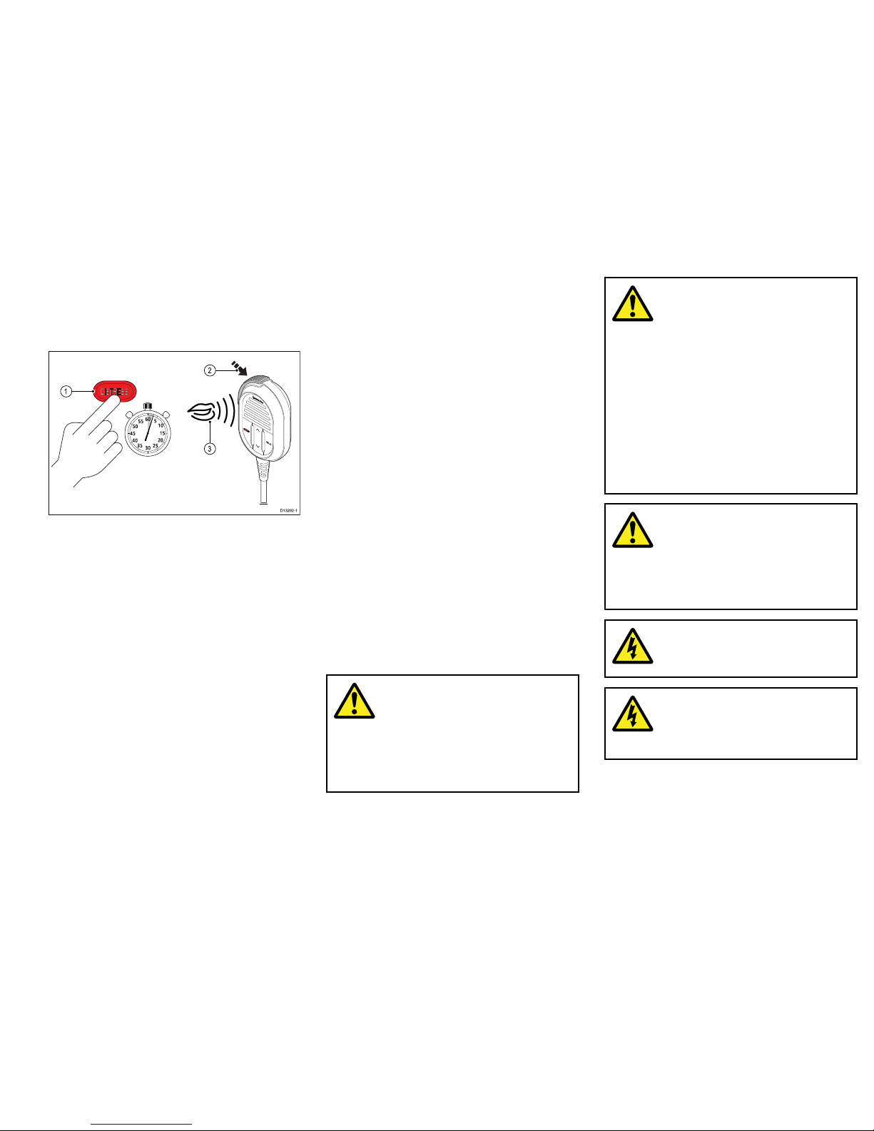
Makingadistresscall
Inanemergencyyoucanuseyourunittomakean
automaticDSCdistresscall.
Withthespringloadedcoveropen:
10
15
20
25
30
35
40
45
50
55
60
5
3
1
2
D13202-1
1.PressandholdtheDISTRESSbuttonfor3seconds.
OncetheDISTRESSbuttonispresseda3second
countdownwillbegin,whenthecountdownreaches
zerotheDSCdistresscallistransmitted.
Thedistresscallisrepeatedautomaticallyuntilitis
acknowledged.
2.PressandholdthePTTbutton,thenslowlyand
clearlyspeakthedetailsofthedistressinthe
followingformat:
MAYDA Y ,MAYDA Y ,MA YDA Y
Thisis<statenameofvessel3times>
MAYDA Y<statenameofvessel1time>
Mypositionis<statelatitudeandlongitude,ortrue
bearinganddistancefromaknownpoint.>
Iam<statenatureofdistresse.g.sinking,onre
etc.>
Ihave<statenumberofpersonsonboardandany
otherinformation—drifting,aresredetc.>
IREQUIREIMMEDIA TEASSIST ANCE
OVER
3.ReleasethePTTbutton.
MakingaMaydaycall
Inanemergencyyoucanuseyourunittomakea
Maydaycall.
1.Pressthe16PLUSbutton.
2.PressandholdthePTTbutton.
3.Slowlyandclearlyspeakthedetailsofthedistress:
MAYDA Y ,MAYDA Y ,MA YDA Y
Thisis<statenameofvessel3times>
MAYDA Y<statenameofvessel1time>
Mypositionis<statelatitudeandlongitude,ortrue
bearinganddistancefromaknownpoint.>
Iam<statenatureofdistresse.g.sinking,onre
etc.>
Ihave<statenumberofpersonsonboardandany
otherinformation—drifting,aresredetc.>
IREQUIREIMMEDIA TEASSIST ANCE
OVER
4.ReleasethePTTbutton.
5.Ifanacknowledgementisnotreceivedthenrepeat
steps2to4above.
Importantinformation
Warning:Readtheexpanded
handbook
Thisdocumentisasubsetofthefull
documentationforyourproduct.For
thecompletedocumentationandsafety
information,pleaserefertotheexpanded
handbook,availableontheRaymarine
website(www.raymarine.com).
Warning:Productinstallation
andoperation
•Thisproductmustbeinstalledand
operatedinaccordancewiththe
instructionsprovided.Failuretodoso
couldresultinpersonalinjury,damage
toyourvesseland/orpoorproduct
performance.
•Raymarinerecommendscertied
installationbyaRaymarineapproved
installer.Acertiedinstallationqualies
forenhancedproductwarrantybenets.
ContactyourRaymarinedealerfor
furtherdetails,andrefertotheseparate
warrantydocumentpackedwithyour
product.
Warning:Potentialignition
source
ThisproductisNOTapprovedforusein
hazardous/ammableatmospheres.Do
NOTinstallinahazardous/ammable
atmosphere(suchasinanengineroomor
nearfueltanks).
Warning:12Voltdconly
Thisproductmustonlybeconnectedtoa
12voltdcpowersource.
Warning:Positiveground
systems
Donotconnectthisunittoasystemwhich
haspositivegrounding.
3
Page 4
Warning:Switchoffpower
supply
Ensurethevessel’spowersupplyis
switchedOFFbeforestartingtoinstallthis
product.DoNOTconnectordisconnect
equipmentwiththepowerswitchedon,
unlessinstructedinthisdocument.
Warning:Chassisgrounding
DoNOTgroundthisproductusingthe
chassisgroundterminal.
Groundingthisproducttoavessel’sRF
groundmaycausegalvaniccorrosion.
Warning:Antennaisolation
Topreventgalvaniccorrosionyourantenna
mustbeisolatedfromanyvesselmetalwork
usingasuitableinsulatede.g.plastic,
mountingbracket.
Warning:Protectunused
cables
Unusedcablesandwiresshouldbe
protectedfromwateringressandfrom
makingcontactwithmetalthatmaybe
grounded.
•Ifsupplied,useprotectivebootstoensure
thatcablesthatarenotconnectedare
protected.
•NEVERleavebareendedwires
uncovered/unprotectedasthiscould
causeashortcircuitandcaninduce
galvaniccorrosion.
Warning:FCCWarning(Part
15.21)
Changesormodicationstothisequipment
notexpresslyapprovedinwritingby
RaymarineIncorporatedcouldviolate
compliancewithFCCrulesandvoidthe
user’sauthoritytooperatetheequipment.
Warning:Maximum
PermissibleExposure
Failuretoobservetheseguidelines
mayexposethosewithinthemaximum
permissibleexposure(MPE)radiusto
RFradiationabsorptionthatexceedsthe
FCCMPElimit.Itistheradiooperator’s
responsibilitytoensurethatnoonecomes
withinthisradius.
Foroptimalradioperformanceandminimal
humanexposuretoradiofrequency
electromagneticenergy,makesurethe
antennais:
•connectedtotheradiobeforetransmitting
•locatedwhereitwillbeawayfrompeople
•locatedatleast1.5meters(5feet)from
theradio’smainunit
Caution:Powersupply
protection
Wheninstallingthisproductensurethe
powersourceisadequatelyprotectedby
meansofasuitably-ratedfuseorautomatic
circuitbreaker.
Caution:Performregularradio
checks
Performregularradiocheckswhenusing
yourvessel,asrecommendedinradio
trainingandcerticationschemesand
radioequipmentrulesofuse.
Caution:Ensureproperradio
use
UndernocircumstancesshouldaDSC
distressalertbesentfromyourradiofor
testpurposes.Suchactionisaviolationof
rulesofuseforradioequipment,andcan
resultinheavynes.
Caution:Productcleaning
Whencleaningproducts:
•Ifyourproductincludesadisplayscreen,
doNOTwipethescreenwithadrycloth,
asthiscouldscratchthescreencoating.
•DoNOTuseabrasive,oracidor
ammoniabasedproducts.
•DoNOTuseajetwash.
Wateringress
Wateringressdisclaimer
Althoughthewaterproofratingcapacityofthis
productmeetsthestatedIPXstandard(refertothe
product’sT echnicalSpecication),waterintrusionand
subsequentequipmentfailuremayoccuriftheproduct
issubjectedtocommercialhigh-pressurewashing.
Raymarinewillnotwarrantproductssubjectedto
high-pressurewashing.
4
Ray52/Ray50/Ray60/Ray70
Page 5

Disclaimer
Raymarinedoesnotwarrantthatthisproductis
error-freeorthatitiscompatiblewithproducts
manufacturedbyanypersonorentityotherthan
Raymarine.
Raymarineisnotresponsiblefordamagesorinjuries
causedbyyouruseorinabilitytousetheproduct,bythe
interactionoftheproductwithproductsmanufactured
byothers,orbyerrorsininformationutilizedbythe
productsuppliedbythirdparties.
FCC
ComplianceStatement(Part15.19)
ThisdevicecomplieswithPart15oftheFCCRules.
Operationissubjecttothefollowingtwoconditions:
1.Thisdevicemaynotcauseharmfulinterference.
2.Thisdevicemustacceptanyinterferencereceived,
includinginterferencethatmaycauseundesired
operation.
FCCInterferenceStatement(Part15.105
(b))
Thisequipmenthasbeentestedandfoundtocomply
withthelimitsforaClassBdigitaldevice,pursuantto
Part15oftheFCCRules.
Theselimitsaredesignedtoprovidereasonable
protectionagainstharmfulinterferenceinaresidential
installation.Thisequipmentgenerates,uses,andcan
radiateradiofrequencyenergyand,ifnotinstalled
andusedinaccordancewiththeinstructions,may
causeharmfulinterferencetoradiocommunications.
However,thereisnoguaranteethatinterferencewill
notoccurinaparticularinstallation.Ifthisequipment
doescauseharmfulinterferencetoradioortelevision
reception,whichcanbedeterminedbyturningthe
equipmentoffandon,theuserisencouragedtotry
tocorrecttheinterferencebyoneofthefollowing
measures:
1.Reorientorrelocatethereceivingantenna.
2.Increasetheseparationbetweentheequipment
andreceiver.
3.Connecttheequipmentintoanoutletona
circuitdifferentfromthattowhichthereceiveris
connected.
4.Consultthedealeroranexperiencedradio/TV
technicianforhelp.
IndustryCanada
ThisdevicecomplieswithIndustryCanada
License-exemptRSSstandard(s).
Operationissubjecttothefollowingtwoconditions:
1.Thisdevicemaynotcauseinterference;and
2.Thisdevicemustacceptanyinterference,including
interferencethatmaycauseundesiredoperation
ofthedevice.
ThisClassBdigitalapparatuscomplieswithCanadian
ICES-003.
IndustrieCanada(Français)
Cetappareilestconformeauxnormesd'exemptionde
licenceRSSd'IndustryCanada.
Sonfonctionnementestsoumisauxdeuxconditions
suivantes:
1.cetappareilnedoitpascauserd'interférence,et
2.cetappareildoitacceptertouteinterférence,
notammentlesinterférencesquipeuventaffecter
sonfonctionnement.
CetappareilnumériquedelaclasseBestconformeà
lanormeNMB-003duCanada.
Licensing
Priortousingthisproductpleasecheckyournational
requirementsforbothoperatorsandequipment
licensing.
StationLicence
FCCstationlicenserequirement
AnFCCShipRadioStationLicenseandCallSignare
notrequiredformostrecreationalvesselstravellingin
USwaters.However,youmustobtainalicenseifyour
vesseltravelstoforeignports.
ShipsthatuseMF/HFsingleside-bandradio,satellite
communications,ortelegraphymustbelicensedbythe
FCC.YoucanobtainaStationLicensebylingFCC
Form605,whichisavailablefromtheFCCwebsite
listedabove.
IndustryCanada
IndustryCanadalicenserequirement
Youdonotneedalicensetooperatethisproductwithin
sovereignwatersofCanadaortheUS.Youwillneeda
licensetooperatethisradiooutsideofCanadaorthe
US.T oobtainIndustryCanadalicensinginformation,
contactthenearesteldorregionalofce,orwrite:
IndustryCanadaRadioRegulatoryBranch
Attention:DOSP
300SlaterStreet
Ottawa,Ontario
Canada,KIAOC8
Europeanlicensingrequirements
RegulationsinsomeareasrequirethatanOperator’s
licenseisobtainedbeforeoperatingaVHFradio.Itis
yourresponsibilitytodeterminewhetheralicenseis
requiredinyourareabeforeoperatingthisequipment.
Additionalinformation–Ray50/Ray52
Thefollowingadditionalinformationisrequiredfor
completingalicenseapplicationinCanadaandtheUS.
IndustryCanada
certicationnumber
4069B-RAY50D
FCCID
PJ5–RAY50
FCCT ypeaccepted
Parts2,15and80
Outputpower1watt(low)and25watt(high)
ModulationFM
Frequencyrange155.500MHzto163.275MHz
5
Page 6
Additionalinformation–Ray60
Thefollowingadditionalinformationisrequiredfor
completingalicenseapplicationinCanadaandtheUS.
IndustryCanada
certicationnumber
4069B-RAY60D
FCCID
PJ5–RAY60
FCCT ypeaccepted
Parts2,15and80
Outputpower1watt(low)and25watt(high)
ModulationFM
Frequencyrange155.500MHzto163.275MHz
Additionalinformation–Ray70
Thefollowingadditionalinformationisrequiredfor
completingalicenseapplicationinCanadaandtheUS.
IndustryCanada
certicationnumber
4069B-RAY70D
FCCID
PJ5–RAY70
FCCT ypeaccepted
Parts2,15and80
Outputpower1watt(low)and25watt(high)
ModulationFM
Frequencyrange155.500MHzto163.275MHz
MaritimeMobileServiceIdentity(MMSI)
Thisproductisaclass“D”DigitalSelectiveCalling
(DSC)device.
A9digitMMSInumberisrequiredtooperateDSC
equipment.Insomeareas,aradiooperatorlicenseis
requiredbeforeanMMSInumbercanbeissued.
Note:Y oucanrequestanMMSInumberfromthe
sameagencythatissuesradioorshipradiolicenses
inyourarea.Onceobtained,youcanprogramthe
MMSInumberintoyourproductbyfollowingthe
instructionsuppliedwiththeproduct.
Onceobtained,youcanprogramtheMMSInumberinto
yourproductusingtheinstructionsprovided.
Ifregulationsinyourareadonotpermityoutoprogram
theMMSInumberyourself,yourRaymarinedealercan
programthenumberforyou.
ObtaininganMMSInumberintheUnitedStates
YoucanrequestanMMSInumberfromtheFCCwhen
youapplyforaStationLicense.Ifyourvesseldoes
notrequirealicense,youmayobtainanMMSIby
contactingBoatUSwww.boatus.com.
ObtaininganMMSInumberinCanada
YoucanobtainanMMSInumberfromyournearest
IndustryCanadaOfce.
ObtaininganMMSInumberinEuropeandrestof
world
AmMMSInumbershouldberequestedfromthesame
agencythatissuesradiooperatorlicensesinyourarea.
AutomaticTransmitterIdentication
System(A TIS)
YourproductincludesA TISfunctionalityforuseonthe
inlandwaterwaysofcontractinggovernmentsofthe
“RegionalArrangementontheRadiocommunication
ServiceforInlandWaterways”—alsoknownas
“RAINWAT”.
ATISaddsdataattheendofradiotransmissionsthat
identiesyourstation.ATISoperationcanbeturnedon
oroffasneededviatheradio’smenu.
AnATISIDcanbeobtainedfromthesameagencythat
issuesradiooperatorlicensesinyourarea.
YourATISIDshouldbeprogramedintoyourproduct
usingtheinstructionsprovided.
Note:ContractingRAINWATcountriesinclude:
Austria,Belgium,Bulgaria,Croatia,theCzech
Republic,France,Germany ,Hungary ,Luxembourg,
Moldova,Montenegro,theNetherlands,Poland,
Romania,Serbia,theSlovakRepublicand
Switzerland.
Note:WhenA TISisenabled,certainprograming
stepshavebeenimplementedtoprotecttheintegrity
oftheRAINWA Tagreement,includingtheblocking
ofDSCfunctionswhenATISisenabled.
EMCinstallationguidelines
Raymarineequipmentandaccessoriesconformto
theappropriateElectromagneticCompatibility(EMC)
regulations,tominimizeelectromagneticinterference
betweenequipmentandminimizetheeffectsuch
interferencecouldhaveontheperformanceofyour
system
CorrectinstallationisrequiredtoensurethatEMC
performanceisnotcompromised.
Note:InareasofextremeEMCinterference,
someslightinterferencemaybenoticedonthe
product.Wherethisoccurstheproductandthe
sourceoftheinterferenceshouldbeseparatedby
agreaterdistance.
ForoptimumEMCperformancewerecommendthat
whereverpossible:
•Raymarineequipmentandcablesconnectedtoitare:
–Atleast1m(3ft)fromanyequipmenttransmitting
orcablescarryingradiosignalse.g.VHFradios,
cablesandantennas.InthecaseofSSBradios,
thedistanceshouldbeincreasedto7ft(2m).
–Morethan2m(7ft)fromthepathofaradarbeam.
Aradarbeamcannormallybeassumedtospread
20degreesaboveandbelowtheradiatingelement.
•Theproductissuppliedfromaseparatebatteryfrom
thatusedforenginestart.Thisisimportanttoprevent
erraticbehavioranddatalosswhichcanoccurifthe
enginestartdoesnothaveaseparatebattery.
•Raymarinespeciedcablesareused.
•Cablesarenotcutorextended,unlessdoingsois
detailedintheinstallationmanual.
6
Ray52/Ray50/Ray60/Ray70
Page 7
Note:Whereconstraintsontheinstallation
preventanyoftheaboverecommendations,
alwaysensurethemaximumpossibleseparation
betweendifferentitemsofelectricalequipment,to
providethebestconditionsforEMCperformance
throughouttheinstallation
AntennamountingandEMEexposure
Ensurethattheantennaisconnectedtotheradio
beforetransmission.
RaymarinedeclaresaMaximumPermissibleExposure
(MPE)radiusof1.5metres(4.9ft)(perOETBulletin
65)forthissystem,assuming25wattsoutputtoan
omnidirectionalantennaof3dBigainorless.
Forwatercraftwithsuitablestructures,theantenna
basemustbeatleast3.5metres(1 1.5ft)abovethe
maindecktomeettheMPEforpersonsupto2metres
(6.6ft)tall.Forwatercraftwithoutsuchstructures,the
antennamustbemountedsothatitsbaseisaminimum
of1.5metres(4.9ft)verticallyfromheadsofallpersons.
Theantennamustbeisolatedfromthevessel’s
metalworkusinganinsulated(e.g.plastic)mounting
bracket.
Connectionstootherequipment
Requirementforferritesonnon-Raymarinecables
IfyourRaymarineequipmentistobeconnectedtoother
equipmentusingacablenotsuppliedbyRaymarine,a
suppressionferriteMUSTalwaysbeattachedtothe
cableneartheRaymarineunit.
Declarationofconformity
RaymarineUKLtd.declaresthatthisproductis
compliantwiththeessentialrequirementsofR&TTE
directive1999/5/EC.
TheoriginalDeclarationofConformitycerticate
maybeviewedontherelevantproductpageat
www.raymarine.com.
Productdisposal
DisposeofthisproductinaccordancewiththeWEEE
Directive.
TheWasteElectricalandElectronicEquipment
(WEEE)Directiverequirestherecyclingofwaste
electricalandelectronicequipment.
Warrantyregistration
ToregisteryourRaymarineproductownership,please
visitwww.raymarine.comandregisteronline.
Itisimportantthatyouregisteryourproducttoreceive
fullwarrantybenets.Yourunitpackageincludesa
barcodelabelindicatingtheserialnumberoftheunit.
Youwillneedthisserialnumberwhenregisteringyour
productonline.Youshouldretainthelabelforfuture
reference.
IMOandSOLAS
Theequipmentdescribedwithinthisdocumentis
intendedforuseonleisuremarineboatsandworkboats
NOTcoveredbyInternationalMaritimeOrganization
(IMO)andSafetyofLifeatSea(SOLAS)Carriage
Regulations.
Technicalaccuracy
Tothebestofourknowledge,theinformationinthis
documentwascorrectatthetimeitwasproduced.
However,Raymarinecannotacceptliabilityforany
inaccuraciesoromissionsitmaycontain.Inaddition,
ourpolicyofcontinuousproductimprovementmay
changespecicationswithoutnotice.Asaresult,
Raymarinecannotacceptliabilityforanydifferences
betweentheproductandthisdocument.Please
checktheRaymarinewebsite(www.raymarine.com)to
ensureyouhavethemostup-to-dateversion(s)ofthe
documentationforyourproduct.
Applicableproducts
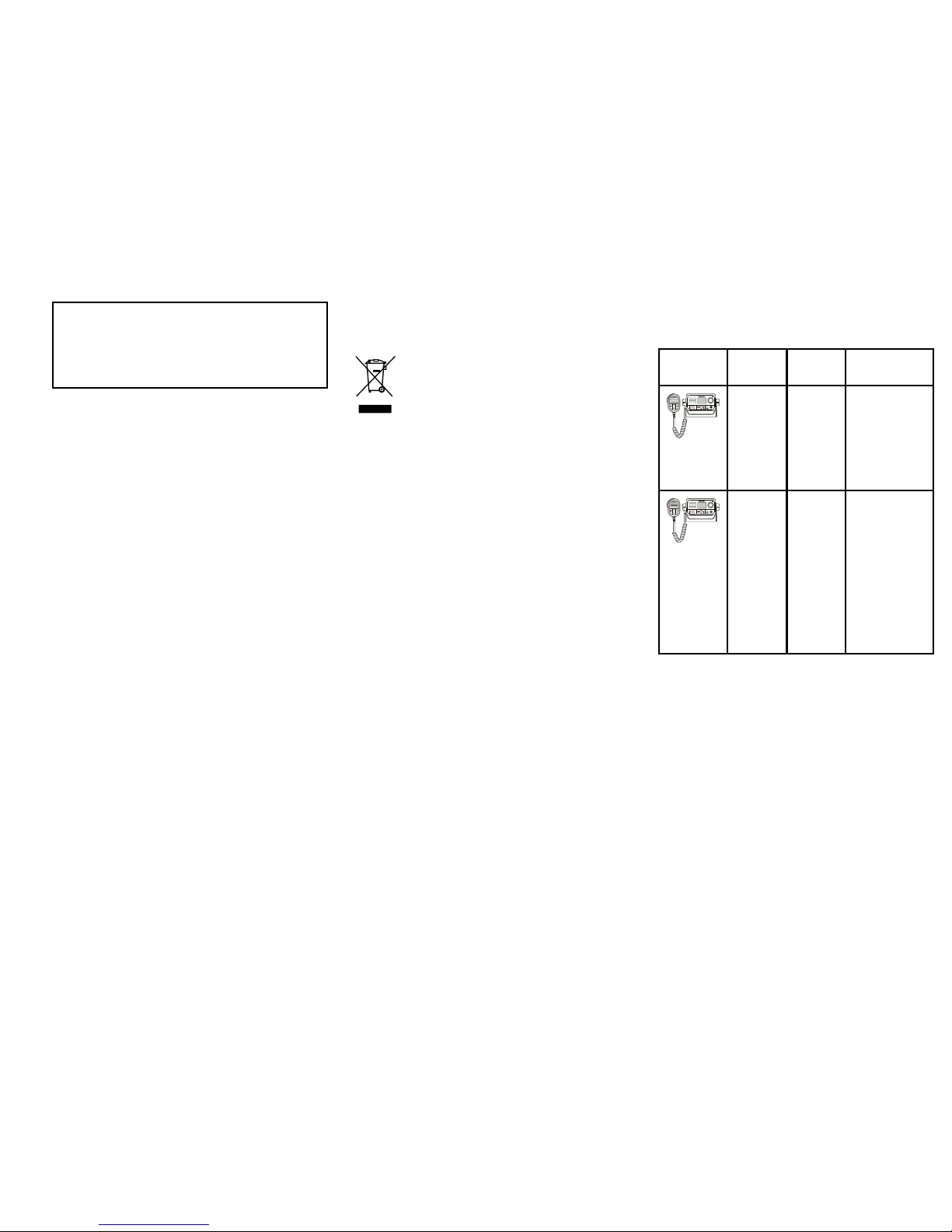
Thisdocumentisapplicabletothefollowingproducts:
Name
Part
numberFeatures
E70243Ray50
•SeaTalk
ng®
/
NMEA2000
•NMEA0183
•Passive
speaker
connection
E70345Ray52
•SeaTalk
ng®
/
NMEA2000
•NMEA0183
•Built-inGNSS
(GPSand
GLONASS)
receiver
•Passive
speaker
connection
7
Page 8
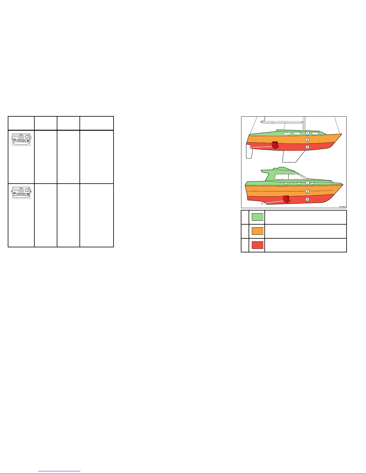
Name
Part
numberFeatures
E70245Ray60
•SeaTalk
ng®
/
NMEA2000
•NMEA0183
•Passive
speaker
connection
•Upto2
stations
E70251Ray70
SameasRay60
withadditional:
•Built-inAIS
receiver
•Built-inGNSS
(GPSand
GLONASS)
receiver
•Loudhailer
connection
Locationandmounting
Generallocationrequirements
Whenselectingalocationfortheunititisimportantto
consideranumberoffactors.
AntennamountingandEMEexposure
Ensurethattheantennaisconnectedtotheradio
beforetransmission.
RaymarinedeclaresaMaximumPermissibleExposure
(MPE)radiusof1.5metres(4.9ft)(perOETBulletin
65)forthissystem,assuming25wattsoutputtoan
omnidirectionalantennaof3dBigainorless.
Forwatercraftwithsuitablestructures,theantenna
basemustbeatleast3.5metres(1 1.5ft)abovethe
maindecktomeettheMPEforpersonsupto2metres
(6.6ft)tall.Forwatercraftwithoutsuchstructures,the
antennamustbemountedsothatitsbaseisaminimum
of1.5metres(4.9ft)verticallyfromheadsofallpersons.
Theantennamustbeisolatedfromthevessel’s
metalworkusinganinsulated(e.g.plastic)mounting
bracket.
Compasssafedistance
Topreventpotentialinterferencewiththevessel's
magneticcompasses,ensureanadequatedistanceis
maintainedfromtheproduct.
Whenchoosingasuitablelocationfortheproductyou
shouldaimtomaintainthemaximumpossibledistance
fromanycompasses.Typicallythisdistanceshouldbe
atleast1m(3ft)inalldirections.Howeverforsome
smallervesselsitmaynotbepossibletolocatethe
productthisfarawayfromacompass.Inthissituation,
whenchoosingtheinstallationlocationforyourproduct,
ensurethatthecompassisnotaffectedbytheproduct
whenitisinapoweredstate.
GPSlocationrequirements
Inadditiontogeneralguidelinesconcerningthe
locationofmarineelectronics,thereareanumber
ofenvironmentalfactorstoconsiderwheninstalling
equipmentwithaninternalGPSantenna.
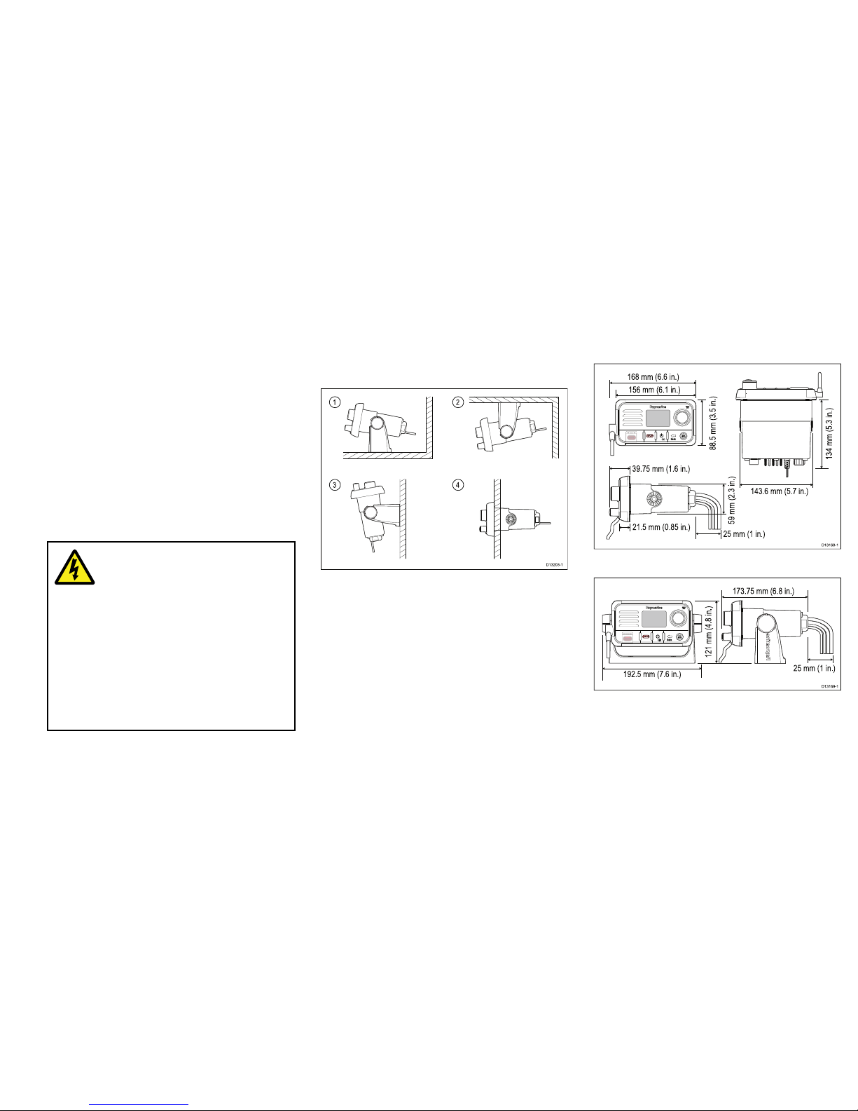
Mountinglocation
•AboveDecksmounting:
ProvidesoptimalGPSperformance.(Forequipment
withappropriatewaterproofrating.)
•BelowDecksmounting:
GPSperformancemaybelesseffectiveandmay
requireanexternalGPSantennamountedabove
decks.
D11537-2
1
2
3
1
2
3
1
.
ThislocationprovidesoptimalGPSperformance
(abovedecks).
2
.
Inthislocation,GPSperformancemaybeless
effective.
3
.
ThislocationisNOTrecommendedforGPS
antenna.
Vesselconstruction
Theconstructionofyourvesselcanhaveanimpact
onGPSperformance.Forexample,theproximityof
heavystructuresuchasastructuralbulkhead,orthe
interioroflargervesselsmayresultinareducedGPS
signal.BeforelocatingequipmentwithaninternalGPS
antennabelowdecks,seekprofessionalassistance
andconsideruseofanexternalGPSantennamounted
abovedecks.
Prevailingconditions
Theweatherandlocationofthevesselcanaffectthe
GPSperformance.Typicallycalmclearconditions
provideforamoreaccurateGPSx.Vesselsat
extremenortherlyorsoutherlylatitudesmayalso
receiveaweakerGPSsignal.GPSantennamounted
belowdeckswillbemoresusceptibletoperformance
issuesrelatedtotheprevailingconditions.
8
Ray52/Ray50/Ray60/Ray70
Page 9
Ventilationrequirements
Toprovideadequateairow:
•Ensurethatequipmentismountedinacompartment
ofsuitablesize.
•Ensurethatventilationholesarenotobstructed.
•Ensureadequateseparationofequipment.
Mountingsurfacerequirements
Ensureunitsareadequatelysupportedonasecure
surface.DoNOTmountunitsorcutholesinplaces
whichmaydamagethestructureofthevessel.
Cableroutingrequirements
Ensuretheunitismountedinalocationwhichallows
properroutingandconnectionofcables:
•Minimumcablebendradiusof100mm(3.94in)is
requiredunlessotherwisestated.
•Usecablesupportstopreventstressonconnectors.
Warning:Protectunused
cables
Unusedcablesandwiresshouldbe
protectedfromwateringressandfrom
makingcontactwithmetalthatmaybe
grounded.
•Ifsupplied,useprotectivebootstoensure
thatcablesthatarenotconnectedare
protected.
•NEVERleavebareendedwires
uncovered/unprotectedasthiscould
causeashortcircuitandcaninduce
galvaniccorrosion.
Electricalinterference
Selectalocationthatisfarenoughawayfrom
devicesthatmaycauseinterference,suchasmotors,
generatorsandradiotransmitters/receivers.
Powersupply
Selectalocationthatisascloseaspossibletothe
vessel’sDCpowersupply.Thiswillhelptokeepcable
runstoaminimum.
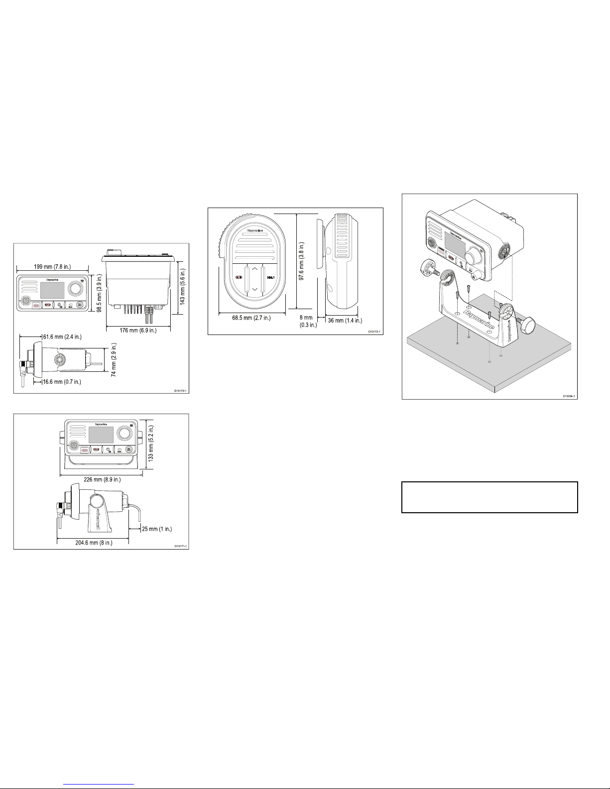
Mountingoptions
Theproductcanbemountedinthefollowing
congurations.
D13203-1
1 2
3 4
1.Tabletopmount
2.Overheadmount
3.Bulkheadmount
4.Panelmount
Productdimensions
Ray50/Ray52productdimensions
TheRay50/Ray52canbepanelmountedorbracket
mounted.
Ray50/Ray52dimensions(panelmount)
168 mm (6.6 in.)
156 mm (6.1 in.)
88.5 mm (3.5 in.)
134 mm (5.3 in.)
59 mm (2.3 in.)
143.6 mm (5.7 in.)
39.75 mm (1.6 in.)
21.5 mm (0.85 in.)
25 mm (1 in.)
D13168-1
Ray50/Ray52dimensions(bracketmount)
192.5 mm (7.6 in.)
121 mm (4.8 in.)
173.75 mm (6.8 in.)
25 mm (1 in.)
D13169-1
9
Page 10
Ray60andRay70productdimensions
TheRay60andRay70canbepanelorbracket
mounted.
Ray60andRay70dimensions(panelmount)
D13170-1
199 mm (7.8 in.)
61.6 mm (2.4 in.)
16.6 mm (0.7 in.)
176 mm (6.9 in.)
98.5 mm (3.9 in.)
143 mm (5.6 in.)
74 mm (2.9 in.)
Ray60andRay70dimensions(bracketmount)
D13171-1
133 mm (5.2 in.)
226 mm (8.9 in.)
204.6 mm (8 in.)
25 mm (1 in.)
Fistmicdimensions
68.5 mm (2.7 in.)
36 mm (1.4 in.)
8 mm
(0.3 in.)
97.6 mm (3.8 in.)
D13172-1
TheFistmic’stted,coiledleadcanbeextended
comfortablytoapproximately1meter(3.3ft.)
Bracketmounting
Followthestepsbelowtomounttheproductonit’s
bracket.
Beforemountingtheunitensurethatyouhave:
•Selectedasuitablelocation,ensuringthereisnothing
behindthemountingsurfacethatmaybedamaged
whendrilling.
•Identiedthecableconnectionsandroutethatthe
cableswilltake.
•Attachedthefrontbezel.
D13204-1
1.Markthelocationofthebracketmountingholeson
themountingsurface.
2.Drillholesforthemountingxingsusingadrillwith
asuitablesizeddrillbit.
3.Usethexingsprovidedtoattachthebracket
securelytothemountingsurface.
4.Attachtheunittothebracketandsecureinplace
usingthebracketmountingknobs.
Note:Drillbit,tapsizeandtighteningtorqueis
dependentonthethicknessandtypeofmaterialthe
unitistobemountedon.
10
Ray52/Ray50/Ray60/Ray70
Page 11
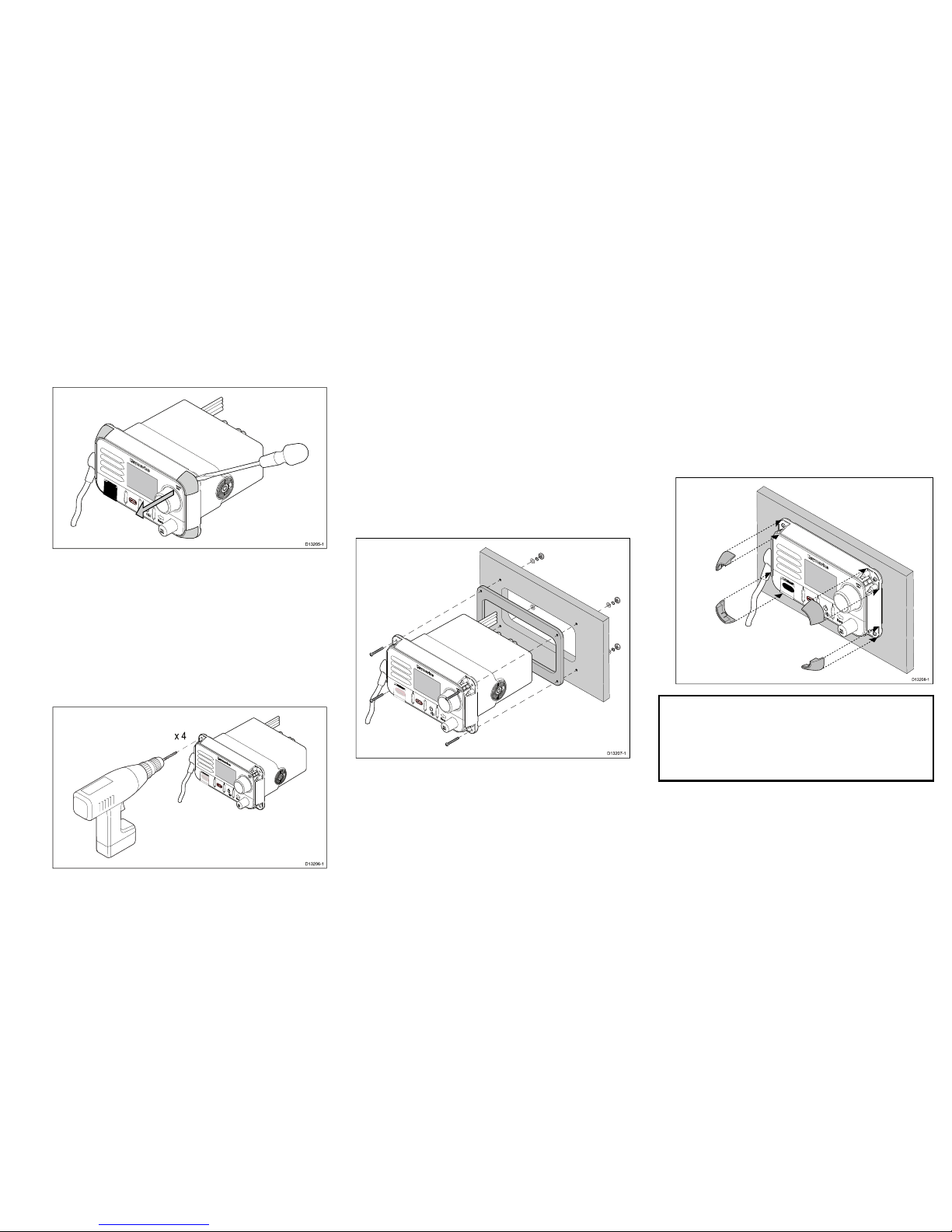
Ray50/Ray52Panelmounting
Removingthemountingholecovers—Ray50/
Ray52
BeforetheRay50/Ray52canbepanelmountedthe
mountingholecoversmustberemoved.
D13205-1
1.Usingaatbladescrewdriver,insertthetipofthe
screwdriverintheslotbetweenthebackofthe
coverandtheunit.
2.Carefullyleverthecoverforwardawayfromtheunit.
3.Repeatsteps2and3fortheremainingmounting
holecovers.
Drillingoutthemountingholes–Ray50/Ray52
Themountingholesmustbedrilledout.
Guidesforthemountingholescanbefoundonthe
cornersoftheunit,underthemountingholecovers.
x 4
D13206-1
1.Usingadrillanda4mm(5/32)drillbit,drilloutthe
4mountingholes.
Holesshouldbedrilledfromthefrontoftheunit,
takingcarenottodamagetheunitbyapplyingtoo
muchforcetothedrill.
Panelmounting–Ray50/Ray52
TopanelmounttheRay50/Ray52,followthesteps
below.
Beforemountingtheproduct,ensurethatyouhave:
•Selectedasuitablelocation,ensuringthereisnothing
behindthemountingsurfacethatmaybedamaged
whendrilling/cutting.
•Identiedthecableconnectionsandroutethatthe
cableswilltake.
•Removedthemountingholecovers.
•Drilledoutthemountingholesontheunit.
D13207-1
1.Checktheselectedlocationfortheunit.Aclear,
atareawithsuitableclearancebehindthepanel
isrequired.
2.Fixthesuppliedmountingtemplatetotheselected
location,usingmaskingorself-adhesivetape.
3.Usingasuitableholesaw(thesizeisindicatedon
thetemplate),makeaholeineachcornerofthe
cut-outarea.
4.Usingasuitablesaw,cutalongtheinsideedgeof
thecut-outline.
5.Ensurethattheunittsintotheremovedareaand
thenlearoundtheroughedgeuntilsmooth.
6.Drill4holesasindicatedonthetemplatetoaccept
thexings.
7.Removethebackingsfromthesuppliedgasket.
8.Placethegasketinpositiononthebackoftheunit
andpressrmlyontotheange.
9.Connectthepower ,andothercablestotheunit.
10.Slidetheunitintoplaceandsecureusingthexings
provided.
11.Attachthemountingholecovers.
D13208-1
Note:Thesuppliedgasketprovidesasealbetween
theunitandasuitablyatandstiffmountingsurface
orbinnacle.Thegasketshouldalwaysbeused.
Itmayalsobenecessarytouseamarine-grade
sealantifthemountingsurfaceorbinnacleisnot
entirelyatandstifforhasaroughsurfacenish.
Ray60/Ray70Panelmounting
Drillingoutthemountingholes–Ray60/Ray70
Beforepanelmountingtheproductthemountingholes
mustbedrilledout.
Guidesforthemountingholescanbefoundinthe
cornersoftheunit,underthefrontbezel.
11
Page 12
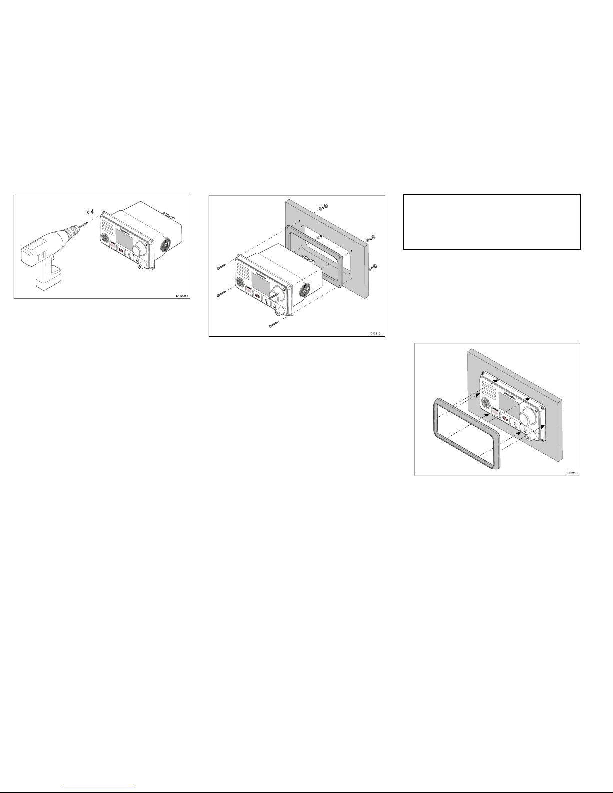
x 4
D13209-1
1.Usingadrillanda4mm(5/32)drillbit,drilloutthe
4mountingholes.
Holesshouldbedrilledfromthefrontoftheunit,
takingcarenottodamagetheunitbyapplyingtoo
muchforcetothedrill.
Panelmounting–Ray60/Ray70
TopanelmounttheRay60/Ray70followthesteps
below.
Beforemountingtheproduct,ensurethatyouhave:
•Selectedasuitablelocation,ensuringthereisnothing
behindthemountingsurfacethatmaybedamaged
whendrilling/cutting.
•Identiedthecableconnectionsandroutethatthe
cableswilltake.
•Drilledoutthemountingholesontheunit.
•Removedthefrontbezel.
D13210-1
1.Checktheselectedlocationfortheunit.Aclear,
atareawithsuitableclearancebehindthepanel
isrequired.
2.Fixthesuppliedmountingtemplatetotheselected
location,usingmaskingorself-adhesivetape.
3.Usingasuitableholesaw(thesizeisindicatedon
thetemplate),makeaholeineachcornerofthe
cut-outarea.
4.Usingasuitablesaw,cutalongtheinsideedgeof
thecut-outline.
5.Ensurethattheunittsintotheremovedareaand
thenlearoundtheroughedgeuntilsmooth.
6.Drill4holesasindicatedonthetemplatetoaccept
thexings.
7.Removethebackingsfromthesuppliedgasket.
8.Placethegasketinpositiononthebackoftheunit
andpressrmlyontotheange.
9.Connectthepower ,andothercablestotheunit.
10.Slidetheunitintoplaceandsecureusingthexings
provided.
11.Attachthefrontbezel.
Note:Thesuppliedgasketprovidesasealbetween
theunitandasuitablyatandstiffmountingsurface
orbinnacle.Thegasketshouldalwaysbeused.
Itmayalsobenecessarytouseamarine-grade
sealantifthemountingsurfaceorbinnacleisnot
entirelyatandstifforhasaroughsurfacenish.
Attachingthefrontbezel–Ray60/Ray70
Afterinstallationthefrontbezelcanbeattached
followingthestepsbelow.
Thefollowingprocedureassumesthattheunithas
alreadybeenmountedinposition.
1.Orientatethebottom-rightsideofthebezelunder
thebottom-rightsideoftheunit,ensuringthatthe
clipsalongthebottomedgeofthebezellatchinto
position.
D13211-1
2.Ensurethebezeliscorrectlyalignedwiththeunit,
asshown.
3.Applyrmbutevenpressuretothebezelalongthe:
i.Outeredges-workfromthesidesupwardsand
thenalongthetopedge,toensurethatitclips
securelyintoposition.
ii.Inneredges-ensurethatthebezelsitsat.
4.Checkthatallcontrolbuttonsarefreetooperate.
12
Ray52/Ray50/Ray60/Ray70
Page 13
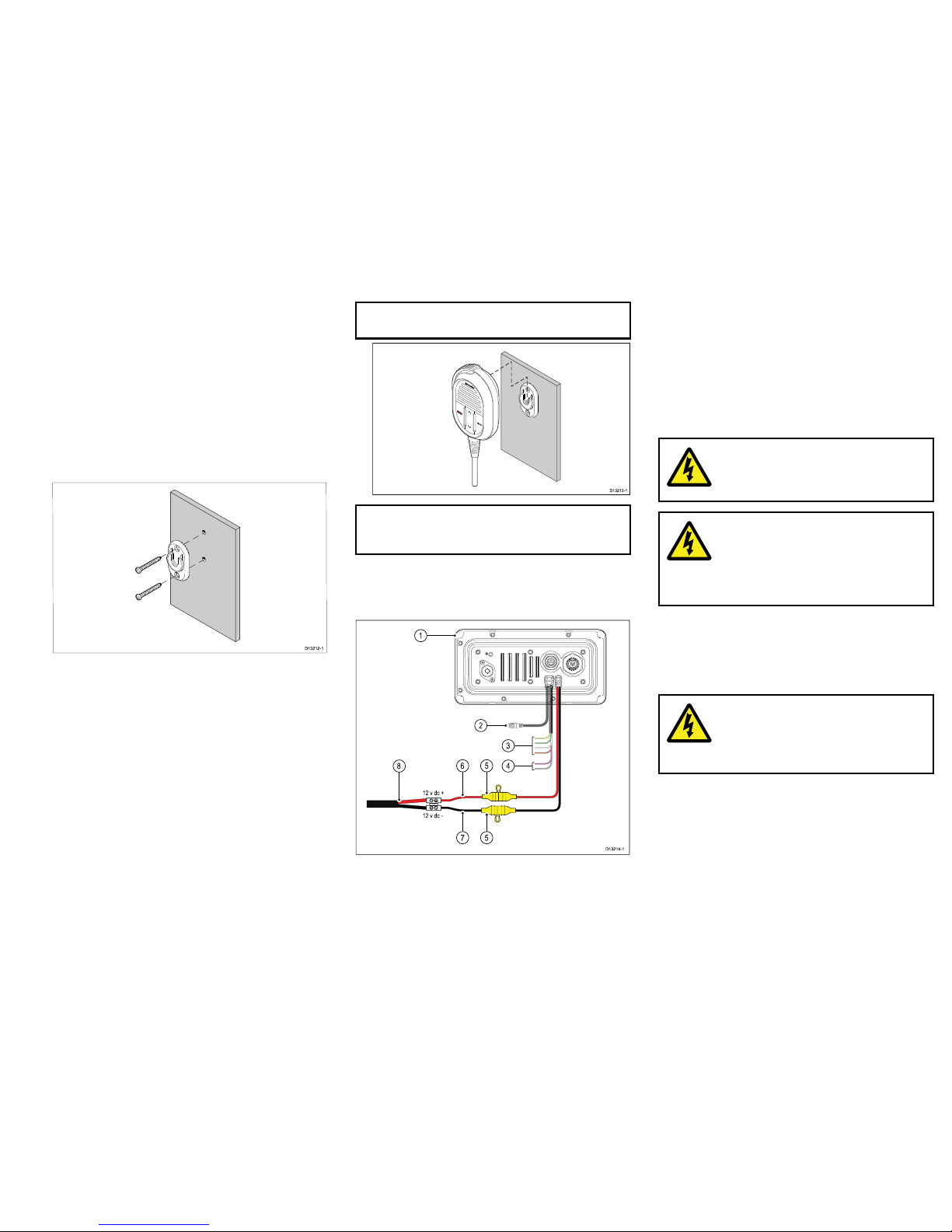
Fistmic/Handsetmounting
TheFistmicandoptionalHandsetcanbemountedby
followingthestepsbelow.WhilstonlytheFistmicis
picturedbelowthestepsareidenticalwhenmounting
theHandsetusingthemountingclip.
Beforemountingtheunit,ensurethatyouhave:
•Selectedasuitablelocation,ensuringthereisnothing
behindthemountingsurfacethatmaybedamaged
whendrilling.
•Identiedthecableconnectionsandroutethatthe
cableswilltake.
D13212-1
0
0
00
1.Checktheselectedlocationforthemountingclip,
aclearatareaisrequired,withsufcientspace
aroundittoplaceandremovetheFistmic/Handset.
2.Usingapencil,offerupthemountingcliptothe
desiredlocationandmarkthelocationofthescrew
holesonthemountingsurface.
3.Drillthemountingholesusingasuitablesizedrillbit.
4.Holdtheclipinplaceandsecureusingthescrews
provided.
5.HooktheFistmic/Handsetovertheclipandgently
pushdownuntilitclicksintoposition.
Note:TheFistmiccanonlybehookedand
unhookedfromthemountingclipwhenheldvertical.
D13213-1
0
00
Note:Drillbit,tapsizeandtighteningtorqueis
dependentonthethicknessandtypeofmaterialthe
unitistobemountedon.
Powerconnection
Thepowersupplyshouldbeconnectedasshown
below:
12 v dc +
12 v dc -
D13214-1
1
2
8
3
4
6
7 5
5
1.Basestation
2.Passivespeakerconnection.
3.NMEA0183wires
4.Loudhailerwires(Ray70only.)
5.In-line10Afuse
6.Redpositivewire
7.Blacknegativewire.
8.Vessel’s12Vdcpowersupply
Warning:12Voltdconly
Thisproductmustonlybeconnectedtoa
12voltdcpowersource.
Warning:Chassisgrounding
DoNOTgroundthisproductusingthe
chassisgroundterminal.
Groundingthisproducttoavessel’sRF
groundmaycausegalvaniccorrosion.
Grounding
Thisproductisgroundedthroughthe0Vdcnegative
wireonthepowercableanddoesnotrequireadrain
(shield)tobeconnectedtothebasestation’sground
terminal.
Warning:Positiveground
systems
Donotconnectthisunittoasystemwhich
haspositivegrounding.
Breakers,fusesandcircuitprotection
Theinformationbelowisprovidedasguidancetohelp
protectyourproduct.Theexampleillustrationsprovided
areforcommonvesselpowerarrangements,ifyouare
unsurehowtoprovidethecorrectlevelofprotection
thenpleaseconsultaRaymarineauthorizeddealerfor
support.
13
Page 14
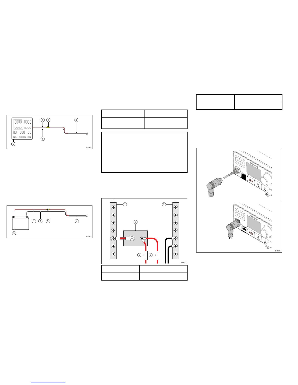
Distributionpanelconnection
Itisrecommendedthatyourproductiswiredthrough
yourvessel’sdistributionpanelviaathermalbreaker
orfuse.
D13092-1
2 31
4
5
1.Vesselpowersupplypositive(+)
2.In-linefuse.(Ifyourproduct’spowercabledoesnot
haveanin-linefusethenoneshouldbetted.)
3.Productpowercable
4.Vesselpowersupplynegative(-)
5.Vesseldistributionpanel
Batteryconnection
Yourproductmaybewireddirectlytothebatteryusing
anin-linefuse.
D13091-1
2 41
5
3
1.Vesselpowersupplypositive(+)
2.Vesselpowersupplynegative(-)
3.In-linefuse.(Ifyourproduct’spowercabledoesnot
haveanin-linefusethenoneshouldbetted.)
4.Productpowercable
5.Vesselbattery
In-linefuseandthermalbreakerratings
Thefollowingin-linefuseandthermalbreakerratings
applytoyourproduct:
In-linefuseratingThermalbreakerrating
10A
7A(ifonlyconnectingone
device)
Note:
•Thesuitablefuseratingforthethermalbreaker
isdependentonthenumberofdevicesyouare
connecting.Ifindoubtconsultanauthorized
Raymarine
®
dealer.
•Yourproduct’spowercablemayhavettedin-line
fuse,ifnotthenyoucanaddanin-linefusetothe
positivewireofyourproductspowerconnection.
Sharingabreaker
Wheremorethan1pieceofequipmentsharesa
breakeryoumustprovideprotectionfortheindividual
circuits.E.g.byconnectinganin-linefuseforeach
powercircuit.
D11637-2
2
4 4
1
3
+
-
1
Positive(+)bar
2
Negative(-)bar
3
Circuitbreaker
4Fuse
Wherepossible,connectindividualitemsofequipment
toindividualcircuitbreakers.Wherethisisnotpossible,
useindividualin-linefusestoprovidethenecessary
protection.
ConnectingtheFistmic–Ray60/Ray70
TheFistmiccanbeconnecteddirectlytotheconnector
onthefrontoftheunit.
D13217-1
1.EnsuretheFistmiccableconnectoriscorrectly
orientated.
2.Fullyinserttheconnectorintotheconnectoronthe
frontoftheunit.
3.Rotatethelockingcollarclockwiseuntilitclicks.
14
Ray52/Ray50/Ray60/Ray70
Page 15
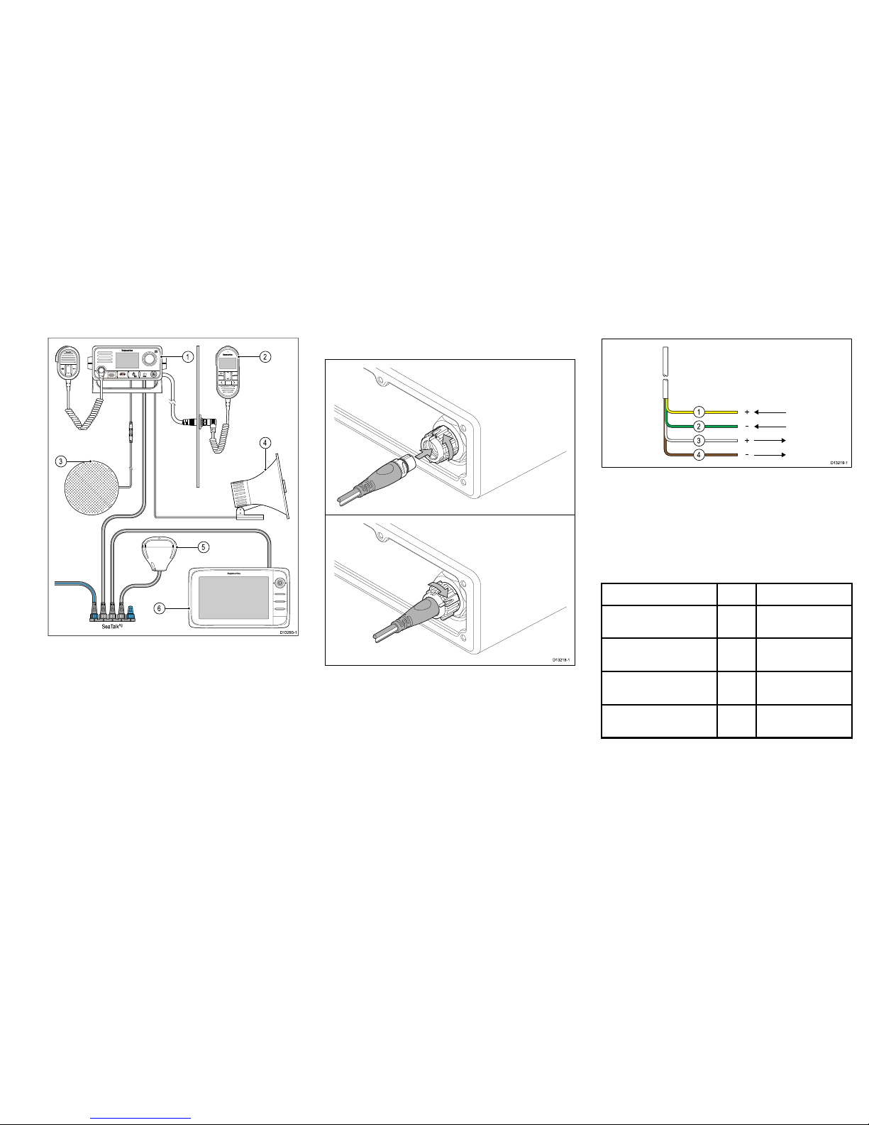
SeaTalk
ng®
connection
TheproductcaninterfacewithRaymarine
®
GPS
orGNSSreceiversandRaymarine
®
multifunction
displaysusingtheSeaT alk
ng®
connection.
SeaTalk
ng
0
0
21
4
5
D13293-1
3
6
1.Ray50/Ray52/Ray60/Ray70
2.OptionalRaymichandsetstation(Ray70and
Ray70only)
3.Optional3rdpartypassivespeaker
4.Loudhailer(Ray70only)
5.GPSReceiver
6.Raymarine
®
Multifunctiondisplay(MFD)
ARaymarine
®
SeaTalk
ng®
GPSorGNSSreceiver
cannotbeconnecteddirectlytotheproduct,asGPS
andGNSSreceiversarepoweredviatheSeaTalk
ng®
backbone.
ConnectingSeaTalk
ng®
BeforeconnectingtoSeaTalk
ng®
,refertothe
SeaTalk
ng®
ReferenceManual,toensurethatthe
maximumpermittedLoadEquivalenceNumber(LEN),
fortheSeaT alk
ng®
backboneisnotexceededoncethis
productisconnected.
D13218-1
1.RotatetheSeaTalk
ng®
connector’slockingcollar
anticlockwise,totheunlockedposition.
2.Ensurethespurcableconnectoriscorrectly
orientated.
3.Fullyinsertthespurcableconnectorintothe
SeaTalk
ng®
connectorontheunit.
4.Rotatethelockingcollarclockwise2clicks,tothe
lockedposition.
NMEA0183connection
TheNMEA0183wirescanbeusedtoconnectthe
unittoa3rdpartyGPS/GNSSreceiverormultifunction
display.
D13219-1
1
2
3
4
+
-
-
+
1.Yellow–Receivepositive(+)wire.
2.Green–Receivenegative(-)wire.
3.White–Transmitpositive(+)wire.
4.Brown–Transmitnegative(-)wire.
TheNMEAwiresshouldbeconnectedtoacompatible
NMEA0183deviceasshowninthetablebelow:
NMEA0183wiresNMEA0183device
Yellow–Receivepositive
(+)
to
Transmitpositive(+)
Green–Receivenegative
(-)
to
Transmitnegative(-)
White–Transmitpositive
(+)
to
Receivepositive(+)
Brown–Transmitnegative
(-)
to
Receivenegative(-)
Connectinganantenna
Theradiomustbeconnectedtoasuitableantenna(not
supplied).Theantennaconnectionmustbeprotected
soitcannotcomeintocontactwithanybaremetal
15
Page 16
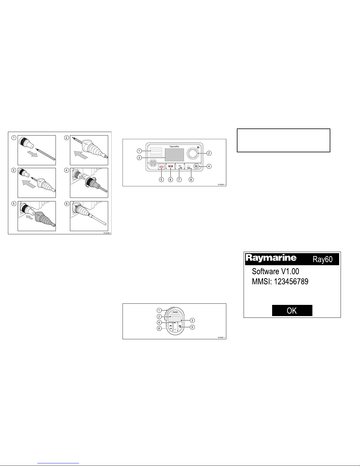
(whichmaybegrounded).Aprotectivebootissupplied
thatcanbeusedtoensureisolationoftheantenna
connection.
1
3
2
4
5
6
D13235-1
1.Disconnectyourantennacablefromtheconnector.
2.Pushtheantennacablethroughthesupplied
protectiveboot.
3.Re-connecttheantennacabletotheconnector .
4.Plugtheantennaconnectorintotheproduct’s
antennaconnectionandsecurebytighteningthe
lockingcollar.
5.Pushtheprotectivebootovertheconnection.
6.Securetheprotectivebootusingthesuppliedcable
ties.
Iftheantennaconnectorcannotberemovedthen
anothersuitablemeansofprotectionmustbeused,
suchaselectricaltape.
Controlsandinterface
Thecontrolsandinterfaceavailableareasfollows:
Basestation
D13220-1
5 6 7 8
1
3
2
4
1.Built-inspeaker
2.Rotaryknob/OKpushbutton—Pressknobin
toaccessmenu/DSCfunctionsandtoconrm
selections.Turnrotaryclockwiseoranti-clockwise
tomoveupanddownthroughmenuitemsorto
changechannelfromtheHomescreen.
3.LCD
4.VOL/SQ—Turnknobtoadjustvolumeorsquelch
upanddown.Presscenterbuttontoswitch
betweenvolumeandsquelchcontrol.
5.DISTRESS—Pushupthespringloadedcoverand
pressthisbuttontomakeaDSCdistresscall.
6.16/PLUS—Whenpoweredonpresstoswitch
betweenprioritychannels.
7.Power—Presstopowertheuniton.Pressand
holdfor3secondstopowertheunitoff.Momentary
presstoaccesstheshortcutlist.
8.Back—Movebackthroughmenuoptions.
Fistmic
D13221-1
2
1
6
4
3
5
1.PTT(PushtoTalk)—Pressandholdtosenda
voicemessage.Releasetoreturntoreceivemode.
Note:Themaximumtransmittimeislimited
to5minutestopreventun-intentional
transmissionsfromoccupyingtheVHF
channel.
2.Speaker
3.Microphonelocation
4.ChannelUpandDown—Changesthechannel
upordown.
5.HI/LO—PresstoswitchbetweenHigh(25W)and
low(1W)transmitpower.
6.16/PLUS—Whenpoweredonpresstoswitch
betweenprioritychannels.
Poweringtheuniton
Withtheradioconnectedtoapowersupplythepower
buttonisusedtoswitchtheradioonandoff.
1.PressthePowerbuttontopower-uptheradio.
Thestartupisdisplayed.
Ray60
Software V1.00
MMSI: 123456789
OK
Thestartupscreenwillautomaticallytime-outafter
5seconds.
2.PresstheOKbutton,orwaitforthestartupscreen
totime-out.
16
Ray52/Ray50/Ray60/Ray70
Page 17
TheHomescreenisdisplayed.
Poweringtheunitoff
Withtheunitpoweredon:
1.PressandholdthePowerbuttonforapproximately
3secondstopowertheunitoff.
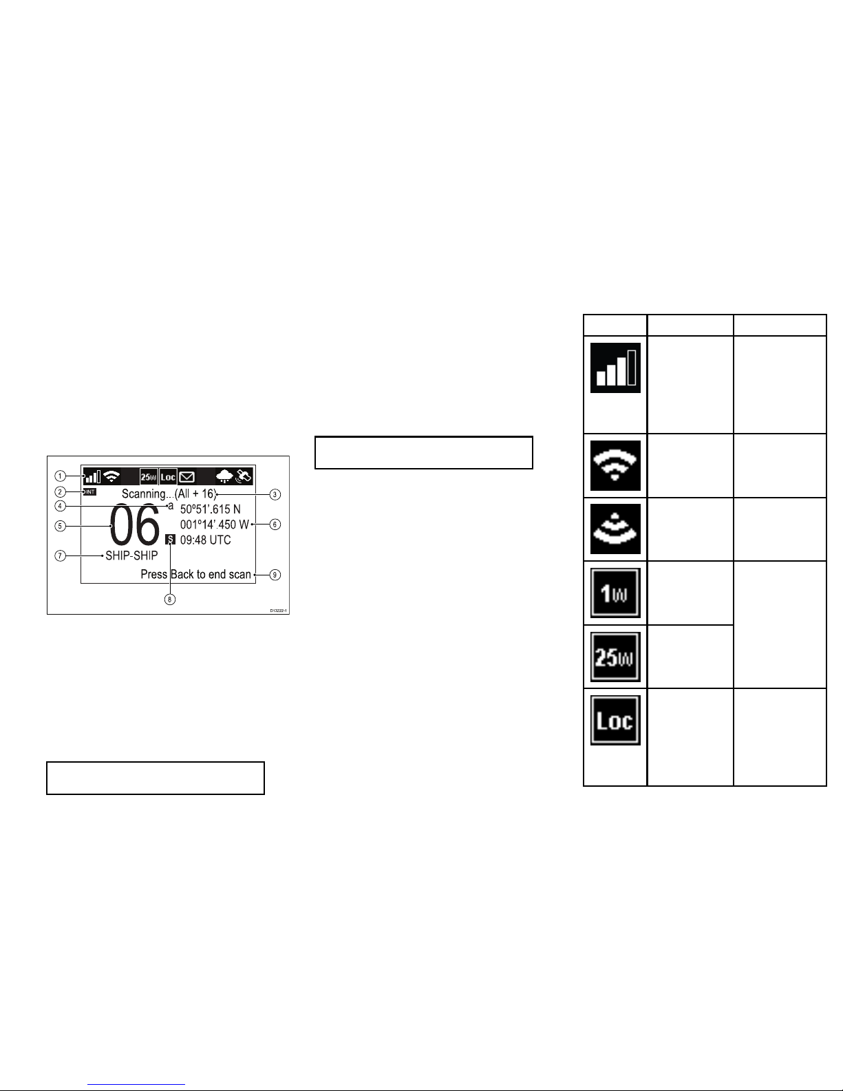
Homescreenoverview
Theinformationbelowdescribestheon-screen
charactersandsymbolswhichtheradiodisplaysonthe
mainscreenandwhattheymean.
INT
06
SHIP-SHIP
s
a
50º51’.615 N
001º14’.450 W
09:48 UTC
ng...(All + 16)
Press Back to end scan
D13222-1
8
1
2
4
5
7
6
9
3
1.Statusbar—Thestatusbardisplayssymbols
whichindicatethecurrentstatusoftheunit.See
Statusbarsymbolsfordetails.
2.Frequencyband—Indicateswhichchannel
frequencybandisinuse:
•USA—UnitedStatesofAmerica
•INT—International
•CAN—Canada
•WX—Weather
Note:Speciallicensingisrequiredtoreceive
USAandCanadianchannelsets.
3.Statustext—Indicatesthecurrentradiomode
e.g.:A TISModeactive,WeatherAlert,Scanmode
etc.
4.Channelsufx
•a—IndicatesthatthecurrentUSorCanadian
channelissimplex.Thischannelusesthe
transmitfrequencyoftheInternationalchannel
fortransmittingandreceiving.Ifachannelis
simplexinall3frequencybands(e.g.channel
06,thechanneldoesnotrequiretheasufx.
•b—Indicatesthatthechannelisareceiveonly
channel.UsedforCanadianchannelsonly .
Note:Y oucannottransmitonareceiveonly
channel.
5.Channel—Indicatesthecurrentchannelnumber
6.Location/TimeorLocation/COG/SOG
—DependingonselectiondisplaysLocation
coordinatesandcurrenttimeorLocation
coordinatesandcurrentCOGandSOG.
7.ChannelName—Indicatesthenameofthe
currentchannel.
8.Channeltype—Indicatesthetypeofchannel:
•s=Simplex—Simplexchannelstransmitand
receiveonthesamefrequency .
•d=Duplex—Duplexchannelsuseseparate
frequenciestotransmitandreceive.
9.Optionaltext—Providesextrauserguidance
Statusbarsymbols
Thestatusbarisusedtodisplayiconsthatindicatethe
radio’sstatus.
SymbolNameDescription
ReceptionsignalIndicatestherelative
strengthoftheradio
signalbeingreceived.
Displaysbetween0
bars(notransmission
beingreceived)and4
bars(strongreception
signal).
TransmitIndicatestheradiois
currentlytransmitting
(e.g.thePTTbutton
isbeingpressed.)
ReceiveIndicatestheradiois
currentlyreceivinga
transmission
Lowpower
Highpower
Indicatestheradio
transmittersisinlow
power(1watt)orhigh
power(25watt)mode
LocalIndicatesthe
radioisinlocal
receptionmode,
whichdecreases
receiversensitivityin
hightrafcareasto
decreaseunwanted
reception
17
Page 18
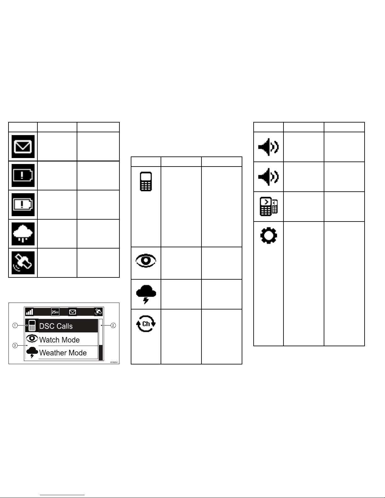
SymbolNameDescription
DSCIndicatesthataDSC
callhasbeenreceived
Powersupply
voltagetoolow
Indicatesthepower
supplytotheradiois
belowthespecied
operatingvoltage
Powersupply
voltagetoohigh
Indicatesthepower
supplytotheradiois
abovethespecied
operatingvoltage
WeatherIndicatesthatthe
weatheralertsmode
isactivated.
GPSFixIndicatesiftheradio
hasaGPS/GNSSx.
Mainmenuoverview
ThemainmenuisaccessedbyPressingtheOKbutton
fromtheHomescreen.
D
SC Calls
Watch Mode
Weather Mode
1
3
2
D13223-1
1.Currentlyselectedmenuitem
2.Scrollbar
3.Menuitems
Themainmenuincludesthefollowingitems:
SymbolNameSub-options
*DSCCalls
•Individualcall
•Distresscall
•Positionrequest
•Groupcall
•Allshipscall
•Phonebook
•Calllogs
•Testcall
•DSCset-up
*WatchMode
•Dualwatch
•Triplewatch
•2ndpriority
channel
*WeatherMode
•Weather
Homescreen
*ScanMode
•Allchannels
•Allchannels+16
•Savedchannels
•Savedchannels+
16
•Editsaved
channels
SymbolNameSub-options
**
Hail/Fog/Intercom
•Hailer
•Foghorn
•Intercom
**Hailer/Foghorn
•Hailer
•Foghorn
**Intercom
•Intercom
Set-up
•Displayset-up
•Language
•Units
•Poweroutput
•Sensitivity
•Keybeep
•Channelset-up
•Weatheralerts
•GPSset-up
•DSCset-up
•AIS
•Networkoutput
•ATISset-up
•Maintenance
18
Ray52/Ray50/Ray60/Ray70
Page 19
Note:
*MenuitemsnotavailablewhenradiohasATIS
enabledoriftheradiohasbeenpre-programedin
MARCOM-Cmode.
**Themenunameandsub-optionsdependonthe
peripheraldevicesconnectedtotheradio.
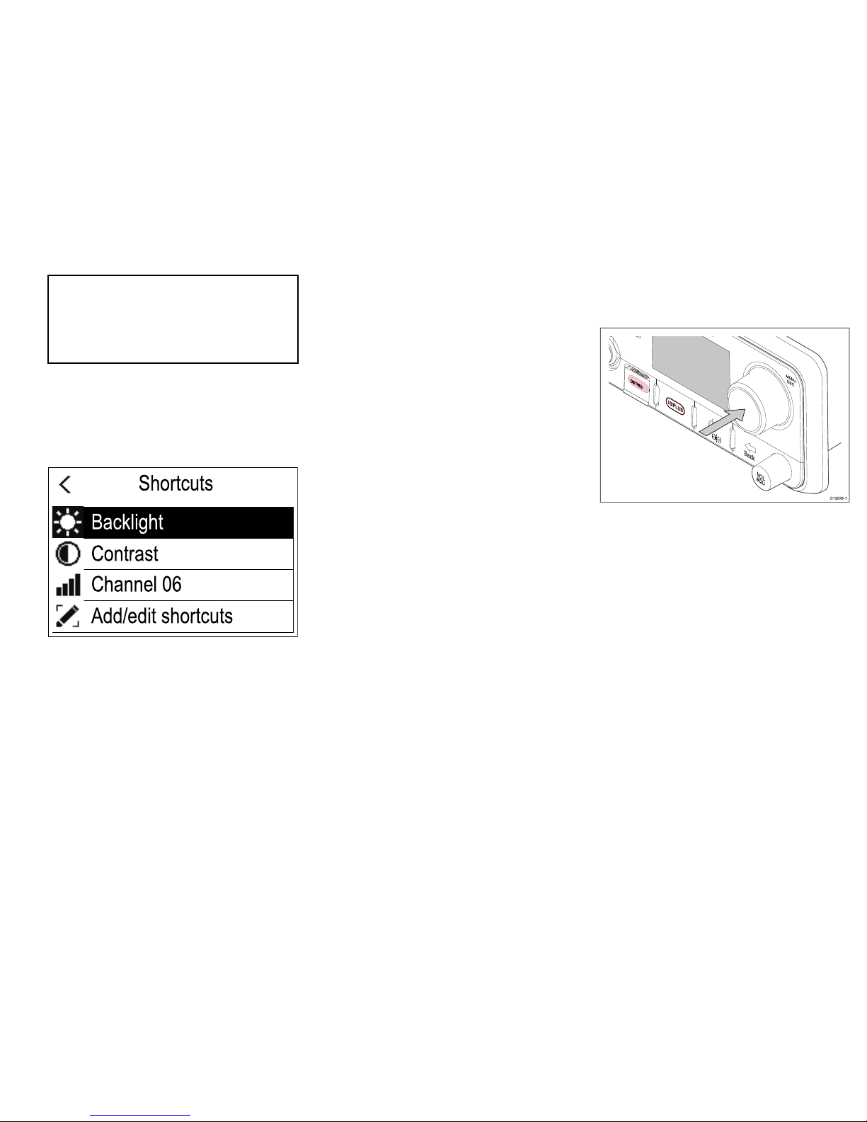
Shortcutlist
PressingthePowerbuttononcewhiletheradiois
switchedonwillopentheShortcutslist.TheShortcuts
listcanbeusedtoadjustthebrightness,contrastand
accessfrequentlyusedfunctions.
Shortcuts
Contrast
Channel 06
Add/edit shortcuts
Backlight
Frequentlyusedfunctionscanbeaddedbyselecting
Add/editshortcuts.
AdjustingBrightnessandContrast
TheLCDBrightnessandContrastcanbeadjusted
usingtheShortcutslist.
Fromanyscreen:
1.PressthePowerbutton.
2.SelectBrightnessorContrast.
3.UsetheRotaryknobtoadjusttheBrightnessor
Contrasttothedesiredlevel.
4.PressthePowerbuttonagaintoreturntothe
previousscreen.
Initialstartup
Unlessyourradiohasbeenpre-programmed;therst
timeyoupower-upyourradioyouwillberequestedto
selectcertainoptions.WiththeexceptionofyourMMSI
andATISID,youwillalsoberequestedtoenterthese
optionsafterafactoryreset.
Afteracknowledgingthestartupscreen,unless
previouslysetyouwillbepromptedtomakethe
followingselections:
1.Languageselection
SeeSelectingalanguageforavailablelanguages.
2.TurnonAISreception—Ray70only
Enablesthebuilt-inAISreceiver.Thisstepisonly
applicabletoradioswithabuilt-inAISreceiver .See
SwitchingontheAISreceiverformoreinformation.
3.Selectnetworktype
SelectswhichconnectiontotransmitAISandDSC
informationtoconnectedequipmenton.Thisstep
isonlyapplicableiftheAISreceiverwasturnedon
inthepreviousstep.SeeSelectinganetworktype
foravailableoptions.
4.EnterMMSInumber
RequiredtoenableDSCfunctions.Thisoptionis
notrequiredafterafactoryreset,oriftheradiohas
beenpre-programedinMARCOM-Cmode,orhas
ATISenabled.SeeEnteringanMMSInumberfor
moreinformation.Ifnotalreadyselectedyouwill
alsobepromptedtoselectyournetworktype.
5.EnterATISID
Requiredwhentheradiowillbeusedinthe
inlandwaterwaysofEurope.Thisstepisonly
applicableiftheradiohasbeenpre-programedin
MARCOM-Cmode.SeeEnteringanA TISIDfor
moreinformation.
6.Frequencybandselection
Setstherelevantchannelsforyourregion.This
stepisnotapplicableiftheradiohasbeen
pre-programedinMARCOM-Cmode.See
Changingtheradioregionformoreinformation.
Accessingthemenu
Theradio’svariousoptionsandsettingsarecontained
withinthemenu.
D13228-1
FromtheHomescreen.
1.PresstheRotaryknob’sOKpushbutton.
Selectingalanguage
Thelanguagetheradiousescanbechanged.
FromtheMainmenu:
1.SelectSet-up.
2.SelectLanguage.
Thelanguagesavailableare:
•English(default)—English
•Español—Spanish
•Français—French
•Deutsch—German
•Italiano—Italian
3.Selectthelanguagethatyouwanttheradiotobe
setto.
TheUserinterfacelanguageischangedtotheselected
language.
19
Page 20

SwitchingontheAISreceiver—
Ray70
TheRay70’sAISreceivercanbeswitchedonoroff.
FromtheMainmenu:
1.SelectSet-up.
2.SelectAIS.
3.SelectOn.
Selectinganetworktype
Whenconnectingyourradiotootherdevicesitis
importanttoensureyouselectthenetworkconnection
andtypethatyouwantdatatobetransmittedover .
FromtheMainmenu:
1.SelectSet-up.
2.SelectNetworkoutput.
Thefollowingnetworktypesareavailable:
•NMEA2000(default)
•0183Highspeed
•0183Stdspeed
3.Selectthenetworktyperelevanttothedevices
connectedtoyourradio.Ifyourradioisnot
connectedtoanyotherdevicesanyoptioncanbe
selected.
Selecting0183Stdspeedwilldisabletheinternal
AISreceiveronaRay70.
TheNetworkoutputsettingdeterminesthebaudrate
oftheNMEA0183input:
NetworkoutputsettingNMEA0183inputbaudrate
NMEA2000
Standardspeed(4800)
NMEA0183HighSpeedHighspeed(38400)
NMEA0183StandardSpeedStandardspeed(4800)
EnteringyourMMSInumber
ToprogramyourradiowithyourMMSInumberfollow
thestepsbelow.
D13224-1
1
2
3
4
FromtheMainmenu:
1.SelectSet-up.
2.SelectDSCset-up.
3.SelectMMSI.
(Notset)willbedisplayedifnoMMSInumberhas
beenset.
4.UsetheRotaryknobtocyclethroughtheavailable
numbersandpressOKtoconrmeachnumberand
movetothenextdigit.
Youshouldonlyentertheunique9digitMMSI
numberprovidedbyyourlicensingauthority .
MMSInumbersstartingwitha‘0’areonlyusedfor
groupsandcoaststations.Ifyouentera‘0’asthe
rstdigittheradiowillassumeyouareenteringa
coaststationMMSIandautomaticallyassigna‘0’as
theseconddigit;thisistoensureagroupMMSIis
notenteredastheradio’suniqueMMSI.
5.PresstheBackbuttonatanytimetoeditdigitsyou
havealreadyentered.
6.PressandholdtheOKbuttontodisplayoptionsto
Movecursorbackandforwardthroughthedigits.
7.WhenthenaldigitisconrmedselectDONE.
Example
Enter MMSI number
987654321
Done
M
PLE
PLE
PLE
PLE
6
5
M
PLE
8.TheMMSIisdisplayedonscreen,checkthatitis
correct,then:
i.SelectY es–Save,or
ii.ifthenumberenteredisnotcorrectselectNo
–Retry.
Caution:MMSIandA TISID
entry
YoucanonlyentertheMMSInumberand
ATISIDonce!
IfyoustoreanincorrectMMSInumberor
ATISIDinyourproduct,itwillhavetobe
resetbyanauthorizedRaymarine
®
dealer.
EnablinganddisablingA TIS
mode
ATISisaEuropeansystemusedonsomeinland
waterways.A TISmustbeenabledandauniqueA TIS
IDenteredinordertouseATISmode.
FromtheMainmenu.
1.SelectSet-up.
2.SelectATISset-up.
20
Ray52/Ray50/Ray60/Ray70
Page 21
3.SelectATIS.
4.SelectOntoenableATISmodeorOfftodisable
ATISmode.
WithATISmodeenabledtheradio’sregionwillbe
xedtotheINT(international)frequencybandand
thefollowingfunctionsaredisabled:
•DSCfunctions
•WatchMode
•ScanMode
•High/lowpowerisrestrictedoncertainchannels
OnceATIShasbeenenabledanATISIDmustbe
entered.
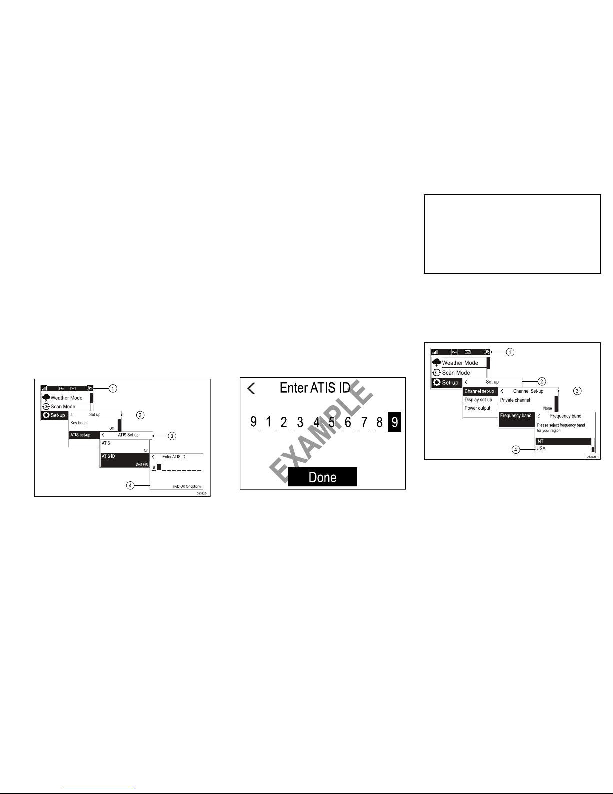
EnteringyourATISID
WhenATISmodeisenabledauniqueATISIDmust
beentered.
D13225-1
1
2
3
4
FromtheMainmenu.
1.SelectSet-up.
2.SelectATISset-up.
3.SelectATISID.
(Notset)willbedisplayedifnoATISIDhasbeen
set.
Therstdigitissettoa‘9’andcannotbechanged,
thisisbecauseallATISIDsstartwitha‘9’.
AsmostATISIDsconsistofa‘9’followedbyyour
9digitMMSInumber;ifyourradioalreadyhasan
MMSInumbertheATISIDwillbepre-lledinthis
format.
4.IftheA TISIDhasbeenpre-lled,checkitcarefully
againstyourissuedATISID.
5.ToenteryourATISIDmanually ,usetheRotary
knobtocyclethroughtheavailablenumbersand
pressOKtoconrmeachnumberandmovetothe
nextdigit.
Youshouldonlyentertheunique10digitATIS
IDprovidedbyyourlicensingauthority.
6.PresstheBackbuttonatanytimetoeditdigitsyou
havealreadyentered.
7.PressandholdtheOKbuttontodisplayoptionsto
Movecursorbackandforwardthroughthedigits.
8.WhenthenaldigitisconrmedselectDONE.
Example
Enter
ATIS ID
Done
9 1
2 3 4 5 6 7 8 9
M
PLE
M
PLE
PLE
PLE
PLE
5
6
9.TheATISIDisdisplayedonscreen,checkthatitis
correct,then:
i.SelectY es–Save,or
ii.ifthenumberenteredisnotcorrectselectNo
–Retry.
Caution:MMSIandA TISID
entry
YoucanonlyentertheMMSInumberand
ATISIDonce!
IfyoustoreanincorrectMMSInumberor
ATISIDinyourproduct,itwillhavetobe
resetbyanauthorizedRaymarine
®
dealer.
Changingtheradioregion
PriortousingtheradioyoumustsettheFrequency
bandtotheregionyourradiowillbeusedin.
FromtheMainmenu:
1
2
3
4
D13326-1
1.SelectSet-up.
2.SelectChannelset-up.
3.SelectFrequencyband.
4.Selecttherelevantregionfromthelist.
Theavailableoptionsare:
•USA
•INT=International
•CAN=Canada
21
Page 22
D13327-1
Makingadistresscall
Inanemergencyyoucanuseyourunittomakean
automaticDSCdistresscall.
Withthespringloadedcoveropen:
10
15
20
25
30
35
40
45
50
55
60
5
3
1
2
D13202-1
1.PressandholdtheDISTRESSbuttonfor3seconds.
OncetheDISTRESSbuttonispresseda3second
countdownwillbegin,whenthecountdownreaches
zerotheDSCdistresscallistransmitted.
Thedistresscallisrepeatedautomaticallyuntilitis
acknowledged.
2.PressandholdthePTTbutton,thenslowlyand
clearlyspeakthedetailsofthedistressinthe
followingformat:
MAYDA Y ,MAYDA Y ,MA YDA Y
Thisis<statenameofvessel3times>
MAYDA Y<statenameofvessel1time>
Mypositionis<statelatitudeandlongitude,ortrue
bearinganddistancefromaknownpoint.>
Iam<statenatureofdistresse.g.sinking,onre
etc.>
Ihave<statenumberofpersonsonboardandany
otherinformation—drifting,aresredetc.>
IREQUIREIMMEDIA TEASSIST ANCE
OVER
3.ReleasethePTTbutton.
MakingaMaydaycall
Inanemergencyyoucanuseyourunittomakea
Maydaycall.
1.Pressthe16PLUSbutton.
2.PressandholdthePTTbutton.
3.Slowlyandclearlyspeakthedetailsofthedistress:
MAYDA Y ,MAYDA Y ,MA YDA Y
Thisis<statenameofvessel3times>
MAYDA Y<statenameofvessel1time>
Mypositionis<statelatitudeandlongitude,ortrue
bearinganddistancefromaknownpoint.>
Iam<statenatureofdistresse.g.sinking,onre
etc.>
Ihave<statenumberofpersonsonboardandany
otherinformation—drifting,aresredetc.>
IREQUIREIMMEDIA TEASSIST ANCE
OVER
4.ReleasethePTTbutton.
5.Ifanacknowledgementisnotreceivedthenrepeat
steps2to4above.
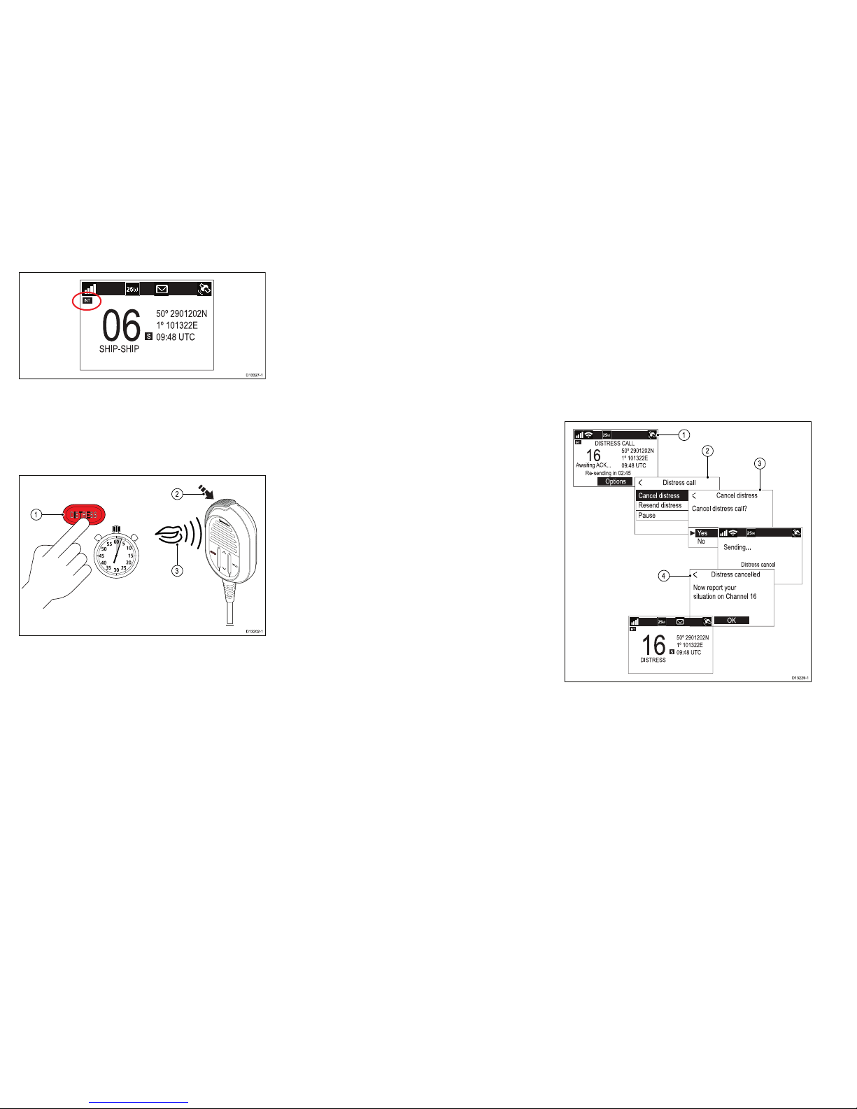
Cancellingadistresscallbefore
transmission
Tocanceladistresscallbeforeitistransmittedfollow
thestepsbelow:
1.ReleasetheDISTRESSbuttonbeforethecount
downtimercompletes.
Whenthebuttonisreleasedyouwillbereturned
tonormaloperation.
Cancellingadistresscallafter
transmission
Adistresscallcanbecancelledafterithasbeen
transmitted.
D13229-1
4
1
2
3
1.SelectOptions.
2.SelectCanceldistress.
3.SelectYestoconrmcancellation.
4.SelectOK.
5.PressandholdthePTTbuttonandmakea
broadcasttoallstationsgivingyourvessel’sname,
callsignandMMSInumberandcancelthefalse
distressalert
22
Ray52/Ray50/Ray60/Ray70
Page 23
Example:“All,Stations,AllStations,AllStations.
Thisis<NAME>,<CALLSIGN>,<MMSIID>,
<POSITION>.Cancelmydistressalertof<DATE>,
<TIME>,<NAME>,<CALLSIGN>”
D13230-1
6.Repeatthebroadcastdescribedinstep5.
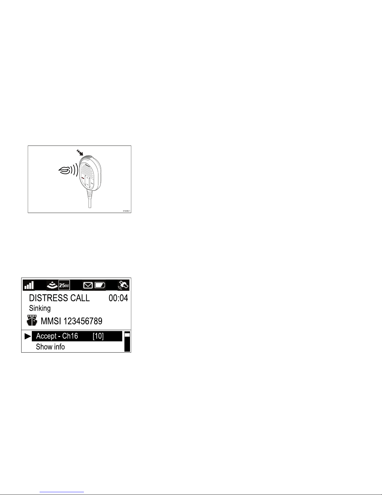
Receivingadistresscall
ItisexpectedthatonlyaCoastRadioStation(CRS)
willacknowledgeDSCdistresscallsandwillactasthe
coordinatorfortherescueoperation.
Whenadistresscallisreceivedanalarmissoundedat
fullvolumeandtheLCDdisplaysinformationrelating
tothedistress.
Show info
Sinking
MMSI 123456789
00:04
Accept - Ch16 [10]
IftheAutochannelchangefunctionisenabled;10
secondsafterreceiptofadistresscalltheradiowill
automaticallyre-tunetochannel16.Otherwisetheuser
ispromptedtochangechannelmanually.
Thedetailsofthedistresscallarerecordedinthe
distresslogandtheenvelopeiconwillashtolet
youknowamessagehasbeenreceived.When
connectedtoaRaymarine
®
multifunctiondisplay
(MFD)thepositiondatafromthedistresscallcanalso
bedisplayedintheChartapplication.
Whenthereceiveddistresscallisacknowledgedbythe
CRSorbyanotherstationtheradiowillresumenormal
operation.
Acknowledgingadistresscall
Distresscallsmustonlybeacknowledgedifthecall
continueswithoutacknowledgementfromaCRS,you
arecloseenoughtothedistressedvesseltobeof
assistanceandarepreparedtorelaythedistresstoa
CRSbyanymeanspossible.ClassDDSCradiosare
forbiddenfromautomaticallyacknowledgingdistress
calls.Acknowledgementmustonlybemadebyvoice
messageonchannel16.
Afterreceivingadistresscallthathasgoneunanswered:
1.Switchtochannel16tolistenforthedistressvoice
message.
2.WaitfortheCRStoacknowledgethecall.
3.Ifthedistresscallisnotacknowledgedbyanother
stationthenacknowledgethecallasfollows:
MAYDA Y
(MMSIofthevesselindistress)
Nameofvesselindistress<repeated3times>
Callsignofthevesselindistress
Thisis<MMSIofyourvessel>,<nameofyour
vesselrepeated3times><callsignofyourvessel>
RECEIVEDMAYDAY
4.YouMUSTthennotifytheshoreauthoritiesbyany
meanspossibletorelaythedistresscall.
MakingaroutineDSCcall
FromtheIndividualCallmenu:Menu→DSCCalls
→IndividualCall.
1.SelectPhonebooktomakearoutinecalltoa
contactsavedinyourPhonebook,or
2.SelectRecentCallstomakearoutinecalltoa
contactthatyouhavecalledrecently,or
3.SelectEnterMMSItomanuallyentertheMMSI
numberofthestationyouwanttocontact.
4.SelectacontactorenteranMMSImanuallyand
presstheOKbutton.
5.SelecttheChannelyouwanttotransmitthecallon.
IftheMMSIisaCSRthentheradiowillautomatically
tunetothecorrectChannel.Theradiowillwaitfor
anacknowledgementtobereceived.
6.Ifanacknowledgementisreceived,presstheOK
button.
7.PressandholdthePTTbuttonandspeakyour
message.
8.ReleasethePTTbuttonwhenyouhavecompleted
yourmessage.
23
Page 24

24
Ray52/Ray50/Ray60/Ray70
Page 25

Page 26

www.raymarine.com
(Ray52)
(Ray50 / Ray60 / Ray70)
 Loading...