

Page 1

Ray240 VHF
Radio
with Digital
Selective Calling
Users Manual
Document # 81219_1
Date: June 2004
Page 2

Trademarks and registered trademarks
Autohelm, HSB Raymarine, RayTech, RayTech RNS, Sail Pilot,
SeaTalk and Sportpilot are registered trademarks of Raymarine
Limited.Apelco is a registered trademark of Raymarine Holdings
Limited (Registered in all major marketing territories).
AST, Autoadapt, Auto GST, Autoseastate, Autotrim, Bidata,
Marine Intelligence, Maxiview, On Board, Raychart, Raynav,
Raypilot, Raystar, ST40, ST60, Seaclutter, Smart Route, Tridata
and Waypoint Navigation are trademarks of Raymarine Limited.
All other product names mentioned are trademarks or registered
trademarks (if applicable) of heir respective companies.
www.raymarine.com
© Copyright - Raymarine 2004
Page 3
How to make a DSC Distress call i
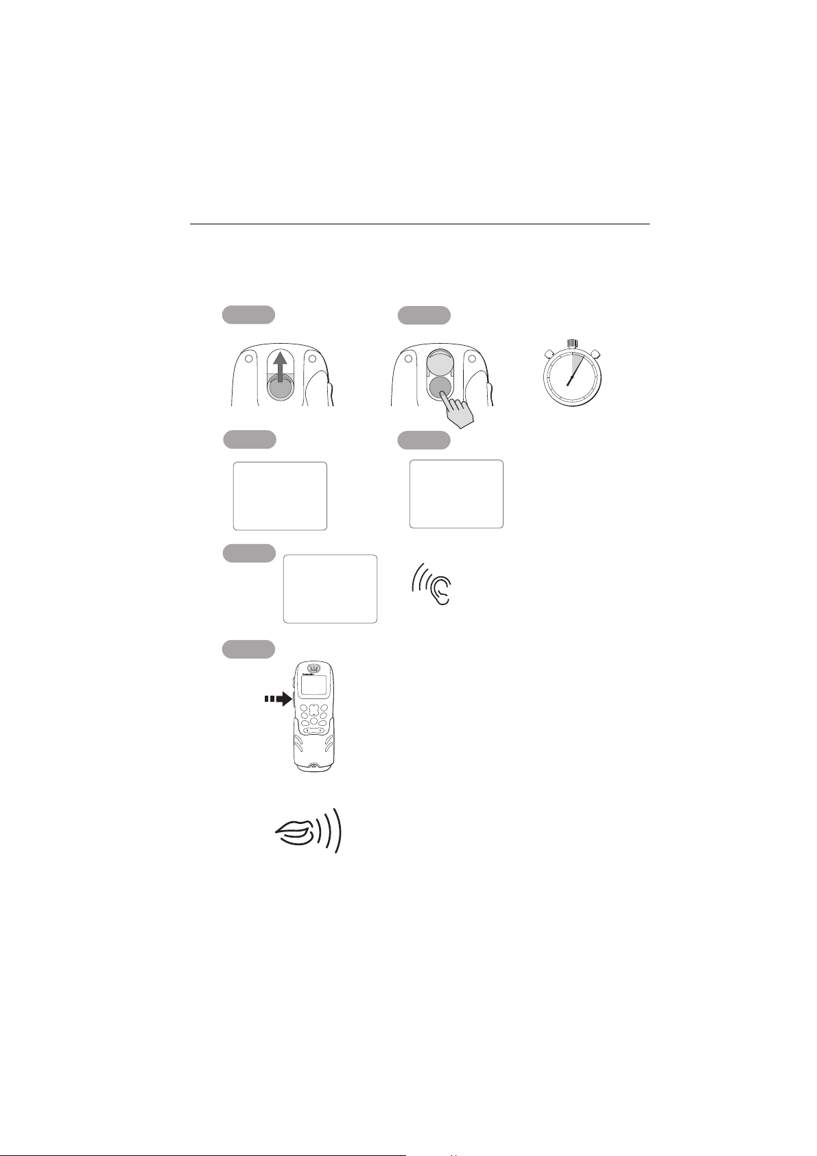
How to make a DSC Distress call
Step 1
Slide up cover
Step 3
Step 2
DISTRESSDISTRESSDISTRESSDISTRESS DISTRESSDISTRESS
Step 4
60
55
50
45
40
35
25
30
PRESS and
HOLD for 5 SECONDS
5
10
15
20
'DISTRESS'
Step 5
Step 6
Press
and
Hold
PTT
DISTRESS
Release
button now
V0:10
SQ:05
25W
RX
16
auto DISTRESS TX
RAY240
LAST/
MENU
WX
OK
CH
16/9 1/25
MEM
SCAN
WATCH
SQ
1
3
2
DEF
ABC
6
4
5
MNO
GHI
JKL
7
8
PQRS9WXYZ
TUV
*
0
THEN
SPEAK
SLOWLY
and
CLEARLY
DISTRESS
sent
WAIT
WHILE
RADIO
AUTOMATICALLY
RE-TUNES
LISTEN
FOR
ACKNOWLEDGEMENT
MAYDAY, MAYDAY, MAYDAY
This is.... (repeat name of vessel 3 times)
MAYDAY
THIS IS.... (name of vessel spoken once)
MY POSITION IS.... (latitude and longitude) or
true bearing and distance from a known point).
IF YOU DON'T KNOW, DON'T GUESS.
I AM.... (sinking, on fire, etc)
I HAVE.... (number of persons on board and any
other information - drifting, flares fired, etc )
I REQUIRE IMMEDIATE ASSISTANCE
OVER
RELEASE THE PTT SWITCH
D6788_1
Page 4
ii Ray240 User Manual
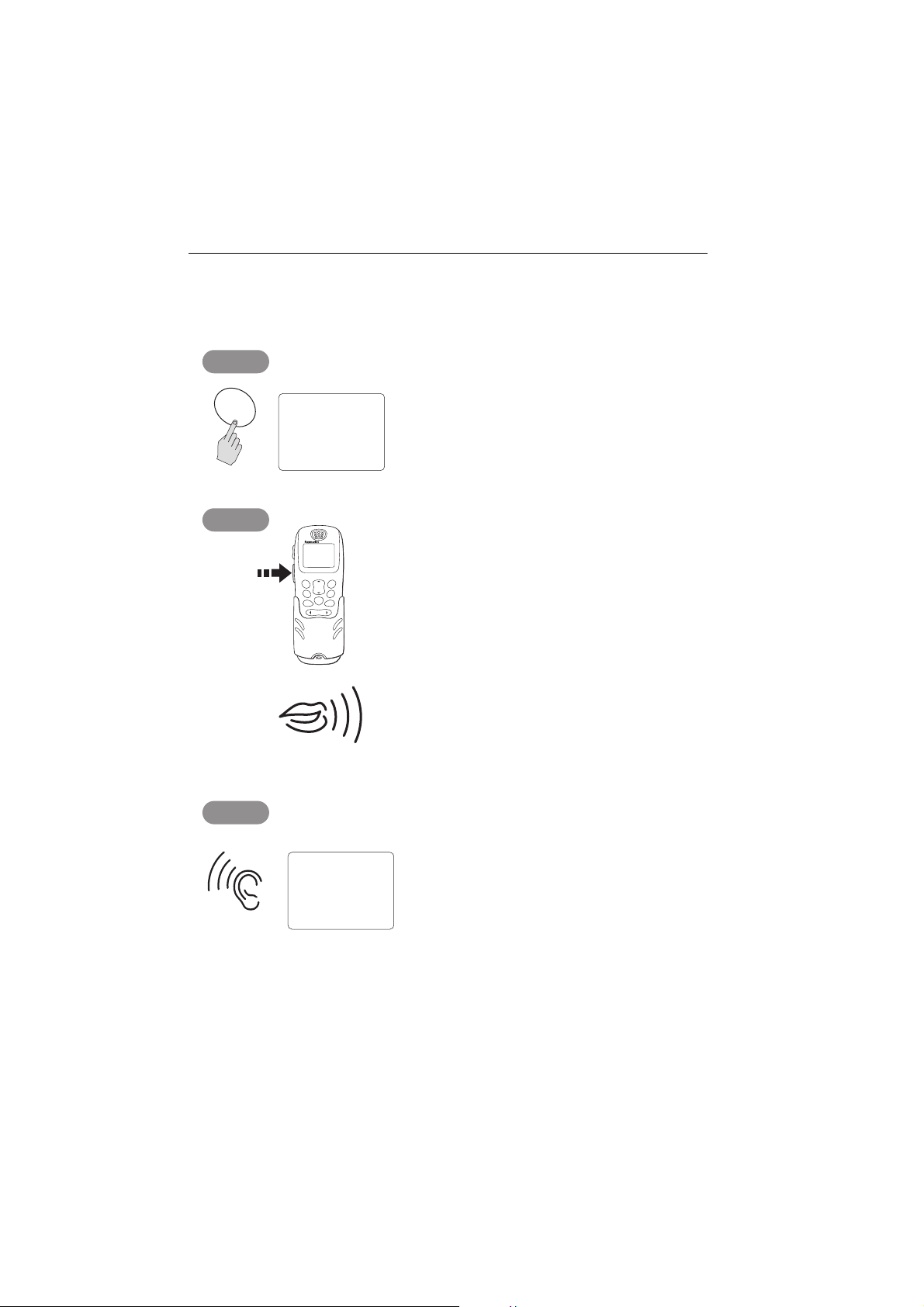
How to make a Mayday call
Step 1
16/9
V0:10
SQ:05
25W
RX
16
MAYDAY, MAYDAY, MAYDAY
This is.... (name of vessel, spoken 3 times)
Step 2
Press
and
Hold
PTT
SLOWLY and CLEARLY
Step 3
V0:10
SQ:05
25W
RX
RAY240
LAST/
MENU
WX
CH
16/9 1/25
MEM
SCAN
WATCH
SQ
1
2
DEF
ABC
4
5
MNO
GHI
JKL
7
8
PQRS9WXYZ
TUV
*
0
THEN
16
MAYDAY
This is....(name of vessel spoken once)
OK
3
6
MY POSITION IS....(latitude and longitude.
or true bearing and distance from a known
point - IF YOU DON'T KNOW, DON'T GUESS).
I AM....(sinking, on fire, etc)
I HAVE.... (number of persons on board and
any other information - drifting, flares fired, etc)
I REQUIRE IMMEDIATE ASSISTANCE
OVER
RELEASE THE PTT SWITCH
FOR ACKNOWLEDGEMENT AND INSTRUCTIONS
IF AN ACKNOWLEDGEMENT IS NOT RECEIVED
D6790_1
THEN REPEAT THE DISTRESS CALL
Page 5

iii
Contents
How to make a DSC Distress call ...........................................................................i
How to make a Mayday call ..................................................................................ii
Contents ................................................................................................................ iii
Important Information .........................................................................................7
Chapter 1: General Information .......................................................................15
1.1 What is the Ray240? ............................................................................ 15
1.2 What is DSC? ........................................................................................ 15
Calls to other ships ........................................................................... 16
Group calls ....................................................................................... 16
Safety broadcasts ............................................................................. 16
Distress alerts ................................................................................... 16
1.3 Can I use the Ray240 as part of an integrated system? ........................ 16
1.4 How do I use the Ray240? .................................................................... 17
Which menu do I need? .................................................................... 19
What does the display tell me? ......................................................... 20
Chapter 2: Operations ........................................................................................21
2.1 Introduction ......................................................................................... 21
2.2 Using the handset - the controls ........................................................... 21
....power the radio On and Off? .................................................. 21
....adjust the handset volume? ................................................... 21
....set the squelch? ..................................................................... 22
....change channels? .................................................................. 22
....tune to the priority channel? .................................................. 22
....monitor channels? ................................................................. 23
....get the weather forecast? ...................................................... 23
....select Private channels? ......................................................... 23
....scan the channels? ................................................................. 24
....use the Memory? ................................................................... 24
....change the transmitting power? ............................................ 24
....navigate the menus? .............................................................. 25
....use the Menu shortcuts? ........................................................ 26
....adjust the active speaker volume? ......................................... 26
2.3 Using the handset - making and receiving calls .................................... 27
....use the intercom? ................................................................... 27
....receive a routine call? ............................................................. 27
2.4 Using the handset - DSC operations ..................................................... 28
....make a DSC phone call? ......................................................... 28
....view phone book details? ....................................................... 29
Page 6

iv
.... add an entry to the DSC phone book? ....................................30
....call another ship? ...................................................................31
....make a specified Distress call? ................................................32
....cancel a Distress call? .............................................................33
....make an All Ships Call (Urgency)? ...........................................34
....make a position request? ........................................................35
.... access the DSC call log? ......................................................... 36
....delete an entry from the DSC call log? ....................................37
2.5 Receiving distress alerts .......................................................................38
Distress calls .....................................................................................38
Distress acknowledgement ...............................................................38
Distress acknowledgement to a call from your radio ..................38
Distress acknowledgement for another vessel? ..........................39
Distress relay .....................................................................................39
2.6 Receiving weather alerts ......................................................................39
2.7 Additional functions .............................................................................39
Intercom/fog/hailer ...........................................................................40
Intercom .....................................................................................40
Fog warnings ..............................................................................40
....set up the automatic fog signal? .............................................41
Hailer ..........................................................................................41
Chapter 3: Installation .......................................................................................43
3.1 EMC Installation Guidelines .................................................................43
3.2 What’s in the box? ................................................................................44
Can I get optional extras? ................................................................. 45
3.3 Where should I install my radio? ........................................................... 46
3.4 Typical installation ................................................................................48
3.5 How much space does the Ray240 need? .............................................49
3.6 How do I make the electrical connections? ...........................................51
3.7 How do I get position data? ..................................................................52
3.8 Setting up the Ray240 ..........................................................................53
.... enter my boat’s MMSI number? .............................................53
....enter my ATIS number? ........................................................... 54
Page 7

v
Chapter 4: Maintenance and Troubleshooting ...............................................55
4.1 Introduction ......................................................................................... 55
4.2 What maintenance can I do? ................................................................ 55
4.3 How do I troubleshoot the Ray240? ..................................................... 55
4.4 How do I get the radio serviced? .......................................................... 56
4.5 How do I contact Raymarine? .............................................................. 57
Appendix A:VHF Channels ..................................................................................59
Appendix B: Technical specification .................................................................67
Appendix C: Hints and Tips .................................................................................69
Appendix D:List Of Abbreviations ....................................................................71
Limited Warranty Certificate - VHF Products ...................................................73
Page 8

vi
Page 9
Important Information 7
Important Information
Purpose
This handbook contains important information on the installation, operation and
maintenance of the US and European versions of the Ray240 VHF radio, which is
intended for light marine use and covers the following models:
• E42001 Ray240 System - US and Canadian version.
• E42002 Ray240E System - European version.
To get the best results in operation and performance, please take the time to read
this handbook thoroughly.
Safety notices
WARNING: Electrical safety
Make sure the power supply is switched off before you make any
electrical connections.
WARNING: Electromagnetic exposure
Failure to observe the Antenna and EME Exposure guidelines may
expose those within the Maximum Permissible Exposure radius
to RF radiation absorption that exceeds the FCC MPE limit. It is
the Radio Operator’s responsibility to ensure that no one is
within this radius before transmitting.
WARNING: Navigation aid
Although we have designed this product to be accurate and
reliable, many factors can affect its performance. As a result, it
should only be used as an aid to navigation and never replace
common sense and navigational judgement. Always maintain a
permanent watch so you can respond to situations as they
develop.
CAUTION: Compass safe distance
The compass safe distance, measured in accordance with EN
60945, for the Ray240 is 0.9 m.
Page 10

8 Ray240 User Manual
FCC Notice
This device complies with Part 15 of the FCC Rules. Operation is subject to the
following conditions:
1. This device may not cause harmful interference.
2. This device must accept any interference received, including interference that
may cause undesired operation.
Changes or modifications to this equipment, not expressly approved in writing by
Raymarine Inc., could violate compliance with FCC rules and void the operator’s
authority to operate the equipment.
EMC conformance
All Raymarine equipment and accessories are designed to the best industry
standards for use in the recreational marine environment. Their design and
manufacture conforms to the appropriate Electromagnetic Compatibility (EMC)
standards, but correct installation is required to ensure that performance is not
compromised.
Antenna mounting and EME exposure
Ensure that the antenna is connected to the radio before transmitting.
Raymarine declares a Maximum Permissible Exposure (MPE) radius of 1.5 meters
(per OET Bulletin 65) for this system, assuming 25 watts output to an
omnidirectional antenna of 3dBi gain or less.
For watercraft with suitable structures, the antenna base must be at least 3.5
meters above the main deck to meet the MPE for persons up to 2 meters tall. For
watercraft without such structures, the antenna must be mounted so that its base
is a minimum of 1.5 meters vertically from the heads of all persons.
Do not transmit when anyone is within the MPE radius of the antenna, unless they
are shielded from the antenna field by a grounded metallic barrier.
Licensing requirements
United States
An Operator License is not required to operate a VHF Marine Radio within US
territorial waters. However, a license is required to operate the radio if you dock in
Page 11

Important Information 9
a foreign port (including Canada and Mexico) or leave a foreign port to dock in a
US port. You can request a Restricted Radiotelephone Operator Permit from the
Federal Communications Commission (FCC) by filing Form 753.
Canada
A license is not required to operate this radio within the sovereign waters of
Canada. You will require a license to operate this radio outside of these waters. To
obtain Industry Canada licensing information, contact the nearest field or
regional office or write to:
Industry Canada
Radio Regulatory Branch
300 Slater Street
Ottawa
Ontario
Canada, K1A 0C8
Attention: DOSP
Europe
Regulations in some areas require that an Operator’s license is obtained before
operating a VHF radio. It is your responsibility to determine whether a license is
required in your area before operating this equipment.
Additional Information
The following additional information will be required for completing a license
application in Canada or the US:
Industry Canada Certification Number 4069BRAY240
FCC ID PJ5RAY240
FCC Type Accepted Parts 2, 15 and 80
Output Power 1 watt (low), 25 Watts (high)
Modulation Frequency
Frequency Range 156.000 - 165.000 MHz
Page 12

10 Ray240 User Manual
Maritime Mobile Service Identity
A nine-digit Maritime Mobile Service Identity (MMSI) number is required to
operate the Digital Selective Calling (DSC) equipment in this radio.
United States
You can request an MMSI number from the FCC when you apply for a Station
License. If your vessel does not require a license, you may obtain an MMSI by
contacting either:
BoatUS (www.boatus.com), or
MariTEL (www. maritelusa.com).
Once obtained, you can program the MMSI number into your Ray240 using the
Menu Operation described in this handbook.
Canada
You can obtain an MMSI number from your nearest Industry Canada Office.
Once obtained you can program the MMSI number into your Ray240 using the
Menu Operation described in this handbook.
Europe
An MMSI number should be requested from the same agency that issues radio
operator licenses in your area.
Once obtained, you can program the MMSI number into your Ray240 using the
Menu Operation described in this handbook.
If regulations in your area do not permit you to program the MMSI number
yourself, your Raymarine dealer can program the number for you.
For full details of programming your MMSI number into the Ray240 - see
Chapter 3:Installation
.
Automatic Transmission Identification System
Some European inland waterways require the use of the Automatic Transmission
Identification System (ATIS). An ATIS number can be requested from the same
agency that issues radio operator licenses in your area.
Once obtained, you can program the ATIS number into your Ray240 using the
Menu Operation described in this handbook.
Page 13

Important Information 11
If the regulations in your area do not permit you to program the ATIS number
yourself, your Raymarine dealer can program the number for you.
For full details of programming your ATIS number into the Ray240 - see
Chapter 3:Installation
.
Handbook information
To the best of our knowledge, the information in this handbook was correct as it
went to press. However, our policy of continuous product improvement and
updating may change specifications without prior notice. As a result, unavoidable
differences between the product and handbook may occur from time to time.
Raymarine cannot accept liability for any inaccuracies or omissions it may
contain.
For the latest product information visit our website:
www.raymarine.com
Warranty
To register your new Raymarine product, please take a few minutes to fill out the
warranty card. It is important that you complete the owner information and
return the card to us to receive full warranty benefits.
Page 14

12 Ray240 User Manual
Page 15

Important Information 13
Certificate No.
RT043
Raymarine Limited Anchorage Park
We
Portsmouth
Hampshire
England P03 5TD
declare, under our sole responsibility, that the products identified in this declaration, and to which this
declaration relates, are in conformity with the essential requirements of European Parliament and Council
Directive:
1999/5/EC on radio equipment and telecommunication terminal equipment and the mutual
recognition of their conformity.
Product Name:
including Class "D" DSC
Product Number(s):
Product Options:
E45003 (Second Active Speaker)
The products have been satisfactorily assessed to Conformity Procedure Annex IV of the Directive and by
application of all or part of the following stan dard(s):
Non-Harmonised Standards(s):
Harmonised Standard(s):
EN 300 698-3, EN 301 843-1, EN 301 843-2,
EN 60950
The assessment is consistent with a Technical Construction File showing conformity with the essential
requirements of the Directive and has been reviewed by Notified Body No
The product is labelled with the CE conformity marking, the identification number of the Notified Body and class
identifier.
Signatory: Name
England PO3 5TD
Date
EN 60945, EN 301 025-1, EN 300 698-1
EN 301 025-2, EN 301 025-3, EN 300 698-2,
Title
Company Name
Company Address
Signature _________________________
Raymarine RAY 240E VHF Radio System
E42002 (without DTMF facility)
E45002 (Second Station Kit)
E45010 (Second Handset)
0191
.
Adil Abbas
International Compliance Manager
Raymarine Limited
Anchorage Park
Portsmouth, Hampshire
March 2004
D7170_1
Page 16

14 Ray240 User Manual
Page 17

Chapter 1: General Information 15
Chapter 1: General Information
1.1 What is the Ray240?
The Ray240 is a combined VHF radio and Class D Digital Selective Calling (DSC)
system, using a phone style handset to access and control all functions. It enables
you to make digitally selected calls, which are quicker and simpler to make than
traditional voice calls using Channel 16. It can transmit and receive on all
available US, Canadian and International Marine VHF channels.
Should a distress situation occur, using the Ray240 you can quickly raise an alert,
automatically indicating your identity and position, and establishing distress
communication on the emergency voice channel.
1.2 What is DSC?
The present VHF radio system requires users to listen until someone speaks, and
then determine whether the call is for them - more often than not, it isn’t. DSC
makes sure that you receive messages, and alerts you to the fact that it is for you.
DSC is part of the Global Maritime Distress and Safety System (GMDSS), a
maritime communication system - not just for emergency and distress messages,
but also for all types of existing ship-to-ship and ship-to-shore routine
communications.
DSC is simply a tone signalling system, which operates on VHF Channel 70 and is
similar to the tone dialling on your phone, but with the ability to include other
information such as your boat’s identification number, the purpose of the call,
your position and the channel you want to speak on.
DSC calls can be divided into four categories:
• Calls to other ships.
•Group calls.
• Safety broadcasts.
• Distress alerts.
Page 18

16 Ray240 User Manual
Calls to other ships
To call another ship or a coast station, you simply enter their dedicated Maritime
Mobile Service Identity (MMSI) number, select your chosen VHF working channel
and send the call - it’s like using a telephone. Both your radio and the one you are
calling automatically switch to the chosen channel for conversation.
Group calls
Wh en gr oups o f ship s need t he sam e inf ormat ion (y acht races, clu b ral lies e tc.) a
special group-call identity can be used to enable restricted broadcast messages.
Safety broadcasts
Safety broadcasts from coast stations and other shipping automatically generate
an alert (ring tone) to ensure that this vital information is not missed.
Distress alerts
At the touch of a button, you can send your ships identity, your position and the
nature of your distress. The position given will be precise and the alert will be
heard immediately by all DSC equipped vessels and coast stations within range.
The message is automatically repeated at approximately 4 minute intervals until
it is acknowledged either by a coast station or a vessel within radio range.
Note:
To transmit precise positions, the radio must be interfaced to your Global
Positioning System (GPS). Otherwise, regular manual position updating is required.
1.3 Can I use the Ray240 as part of an integrated
system?
Your Ray240 can receive position information, e.g. latitude and longitude, using
either of the following protocols:
• National Maritime Electronics Association (NMEA) 0183.
• SeaTalk
enabling DSC integration with other instruments.
You can also add an additional handset and active speaker to the standard
Ray240, giving two fully functional stations with an intercom function. This is
particularly useful where your boat has dual helms or a second navigation station.
Page 19
Chapter 1: General Information 17
S
1.4 How do I use the Ray240?
12
DISTRESS
DISTRESS
1
11
10
RAY240
2
WX
CH
MEM
WATCH
9
SQ
3
RAY240 HANDSET
Product Code: E32002
Input: 11.6 - 15.6 VDC
Raymarine Ltd
Portsmouth PO3 5TD England
FCC ID PJ5RAY240
IC: 4069B-RAY240
GHI
PQRS
1
4
7
*
3
2
DEF
ABC
6
5
MNO
JKL
9
8
WXYZ
TUV
0
4
5
8
7
6
Front Back
D6741_1
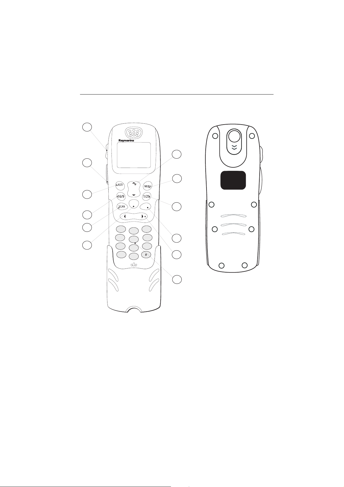
You can access all of the functions of the Ray240, with the exception of adjusting
the active speaker volume, from the handset. The clearly marked buttons and
alpha-numeric keypad make operation simple.
The DISTRESS button can be found beneath a sliding cover on the back of the
handset. By simply sliding the cover up and pressing the button, the DSC Distress
Call procedure is started.
Page 20

18 Ray240 User Manual
1. CHANNEL UP/DOWN moves the selected channel up or down, or scrolls
through the menus.
2. MENU Press to access the menus, or to select a menu option. Press and hold to
access the call menu.
3. 1/25 changes the transmitting power setting from 1 watt (low) to 25 watt
(high) or vice versa.
4. WATCH Press to activate the Dual Watch function (2 channels). Press and hold
to activate the Tri-Watch function (3 channels).
5. SQUELCH mutes any background noise. Also used for the backspace function
when making alpha-numeric entries.
6. Key pad The alpha-numeric keypad has multi-tap operation, the same as a
mobile phone.
7. MEMORY commits a channel to the radio memory.
8. SCAN starts the scanning of available channels. Press to start priority
scanning. Press and hold to start non-priority scanning.
9. 16/9 (16) Press to power up the radio. Press and hold for 5 seconds to power
off the radio. When using the radio, press to re-tune to the priority channel.
10. LAST/WX (PRIV) Press to return to either the last selected channel, or when
navigating the menus to return to the previous screen. Press and hold to access
the Weather channels. (Press and hold to access private channels).
11. Push to Talk Press and hold to send a voice message. Release to return to
receive mode.
Note:
The maximum transmit time is limited to 5 minutes to prevent non-intentional
transmissions from occupying the VHF channel.
12. Volume adjusts the volume of the radio up or down.
Note:
Differences for European versions of the radio are shown in brackets.
Page 21

Chapter 1: General Information 19
Which menu do I need?
Intercom
Hailer
Foghorn - Auto
Main Menu
Foghorn - Manual
Intercom/Hailer/Fog
Phone book
VHF Operations
DSC Operations
ATIS
1
2
Settings
System Information
Add new entry
Select name from list
Radio Sensitivity
Frequency Group
Call
Call All Ships
Call log
Position
Position Request
Settings
ATIS Disable/Enable
ATIS Number
Handset Settings
Display Settings
2
ATIS
Call
Position request
View
Delete
Urgency
Safety
My MMSI Group
My MMSI
Handset 1
Handset 2
Show position
Key beep
Backlighting
Notes: (1)
(2)
Software
Hardware
D6742_1
A Maritime Mobile Service Identity (MMSI) number is required to
operate DSC functions.
ATIS function only available on European models. An Automatic
Transmission Identification System (ATIS) number is required to
operate.
Page 22

20 Ray240 User Manual
What does the display tell me?
The liquid crystal display (LCD) screen will give you the following information in
normal operating mode:
Volume level
Squelch level
Power setting
Operating mode
Volume level
Shows the current volume level. Adjustable from 0 to 10.
Squelch level
Shows the current squelch level. Adjustable from 0 to 10.
Power setting
Shows the power level. 1 watt (low) or 25 watts (high).
Operating mode
Shows which operating mode the radio is in, transmit (TX), or receive (RX).
Active channel
Shows the channel on which the radio is currently operating.
V0:10
SQ:05
25W
RX
Active
Channel
16
Page 23

Chapter 2: Operations 21
VOL
Chapter 2: Operations
2.1 Introduction
This chapter shows you how to operate the controls of the Ray240 and use it to
make the common Digital Selective Calling (DSC) calls. There are many other
useful functions accessed through the Menus, which are listed in detail at the end
of this chapter.
Using the radio is simple. All of the functions, except adjusting the active speaker
volume are controlled from the handset.
Note:
Differences for the European versions of the radio are shown in brackets in the text.
2.2 Using the handset - the controls
How do I
....power the radio On and Off?
Power ON
PRESS the 16/9 (16) button to turn on the radio.
D6744_1
D6745_1
Power OFF
PRESS and HOLD the 16/9 (16) button for 5 seconds.
After a five second countdown the radio powers off.
....adjust the handset volume?
PRESS the volume key on the side of the handset to adjust the
handset volume up or down. Each press of the key raises or lowers
the volume by one level.
Note:
It is not possible to adjust the volume while the radio is in ‘Menu’
mode.
Page 24

22 Ray240 User Manual
How do I
D6746_1
OR
....set the squelch?
PRESS this button to reduce background noise from the receiver.
Press the right arrow to increase the squelch and the left arrow to
decrease it.
The optimum squelch setting is obtained by turning the squelch
down until background noise is heard. Then increase the setting
by one level to reduce this noise.
Note:
It is not possible to adjust the squelch setting while the radio is in
‘Menu’ mode.
....change channels?
Channel UP/DOWN button
Press the Channel UP/DOWN button to change the channels
sequentially.
Keypad
By using the keypad you can directly select the required channel
number.
D6747_1
....tune to the priority channel?
PRESS this button at anytime when using the radio to tune to
the priority channel.
D6744_1
Page 25

Chapter 2: Operations 23
How do I
D6749_1
D6750_1
Dual Watch (2 channels)
PRESS this button to start the Dual Watch function.
The radio keeps operating on the current channel, while
monitoring the priority channel. If activity is detected on the
priority channel it becomes active. When the priority channel is no
longer active the radio resumes Dual Watch.
Tri-Watch (3 channels)
PRESS and HOLD this button to start the Tri-Watch function.
The radio will keep operating on the current channel, while
monitoring the priority channel and the last channel. Activity
detected on any of these channels will make it active. When that
channel is no longer active the radio resumes Tri-Watch.
....get the weather forecast?
PRESS and HOLD this button to access the Weather channels.
Use the channel button to select W0 through to W9 depending
upon which weather channel is required.
Note:
This function is available on US/Canadian versions of the Ray240,
or the European version with the appropriate license.
....monitor channels?
D6751_1
....select Private channels?
PRESS and HOLD the this button to access the Private channels.
Use the channel button to select the required Private channel.
Note:
This function is available only on European versions of the
Ray240.
Page 26

24 Ray240 User Manual
How do I
D6752_1
MEMORY
D6753_1
....scan the channels?
Non-priority scanning
PRESS and HOLD this button for non-priority scanning.
Figure 2-1:The radio will scan the channels in sequence for activity,
automatically tuning to a channel if activity is detected.
Priority scanning
PRESS this button to start priority scanning.
The radio scans the priority channel in between scanning each
channel in sequence. If activity is detected on a channel the radio
automatically tunes to that channel.
....use the Memory?
Create a channel list
To create a channel list, select the first channel required, PRESS and
hold this button.
Add channels by selecting the number and then pressing and
holding this button.
D6754_1
....change the transmitting power?
1/25
PRESS this button to change the transmitting power of the radio
from 1Watt (Low) to 25 Watt (High) and vice versa.
Page 27

Chapter 2: Operations 25
How do I
D6755_1
D6783_1
D6750_1
....navigate the menus?
MENU
PRESS this button to access the menus or to accept a menu option.
CHANNEL UP/DOWN
PRESS this button to scroll through the menu options.
LAST/WX (PRIV)
PRESS this button to return to the previous screen.
16/9 (16)
PRESS this button to return to the priority channel
D6744_1
Page 28

26 Ray240 User Manual
VOL/PWR
How do I
....use the Menu shortcuts?
Press and hold to access the DSC Phone Book. For further
D6755_1
D
6749_1
D6752_1
information refer to -
page 28
PRESS to move the cursor bar to the last item on the current display.
If the cursor is on the last item, the next page, if available, is shown.
PRESS and HOLD to move the cursor bar to the last item in the
menu.
PRESS to move the cursor bar to the top item on the current display.
If the cursor is on the top item, the previous page, if available, is
shown.
PRESS and HOLD to move the cursor bar to the first item in the
selected menu.
How do I ....make a DSC phone call?
on
....adjust the active speaker volume?
Turn the active speaker knob clockwise to turn the speaker on and
increase the volume.
D6756_1
Turn the knob counter-clockwise to decrease the volume and turn
the speaker off.
Page 29

Chapter 2: Operations 27
2.3 Using the handset - making and receiving calls
How do I
STEP 1
MAIN MENU
Intercom/hailer/fog
Phone Book
VHF Operations
DSC Operations
EXIT
OK
STEP 2
Intercom
HAILER
FOG
EXIT
I/H/F
STEP 3
RAY240
THEN
LAST/
MENU
WX
OK
CH
16/9 1/25
MEM
WATCH
SCAN
SQ
1
3
2
DEF
ABC
6
4
5
MNO
GHI
JKL
7
8
PQRS9WXYZ
TUV
*
0
Note:
The intercom function is only available when a second station is installed.
D6784_1
....receive a routine call?
....use the intercom?
OK
STEP 1
STEP 2
INCOMING CALL
33678905
to accept
the call
CANCEL
ANSWER
Any calls that remain unanswered for more than 30 seconds or that you reject are
logged. Any logged information can be retrieved from the Call Log.
to reject
the call
D6785_1
Page 30

28 Ray240 User Manual
2.4 Using the handset - DSC operations
How do I
STEP 1
Either
STEP 2
STEP 4
....make a DSC phone call?
Press and
hold
or
PHONE BOOK
Add an entry
Flying fox
Wave dancer
Sun chaser
EXIT
OK
MAKE CALL
CHANNEL
ENTER CHANNEL NUMBER
-
STEP 3
STEP 5
MAIN MENU
Intercom/hailer/fog
Phone Book
VHF Operations
DSC Operations
EXIT
PHONE BOOK
Call
View details
Delete
EXIT
SHIP-SHIP CALL
Dreamcatcher 68
Press MENU to
make DSC call
OK
OK
STEP 6
AUTOMATICALLY
RE-TUNES TO SELECTED
CHANNEL WHEN AN
ANSWER
IS RECEIVED
STEP 7
Press
and
Hold
PTT
LAST/
WX
16/9 1/25
SCAN
1
4
GHI
7
PQRS9WXYZ
*
D7182_1
RAY240
CH
MEM
SQ
2
ABC
5
JKL
8
TUV
0
MENU
OK
WATCH
3
DEF
6
MNO
THEN
YOUR
MESSAGE
Page 31

Chapter 2: Operations 29
How do I
STEP 1
Either
STEP 2
STEP 4
Press and
hold
Add an entry
Flying fox
Wave dancer
Sun chaser
EXIT
PHONE BOOK
Name: Flying fox
MMSI: 33678085
....view phone book details?
Intercom/hailer/fog
or
Phone Book
VHF Operations
DSC Operations
EXIT
STEP 3
PHONE BOOK
OK
MAIN MENU
PHONE BOOK
Call
View details
Delete
EXIT
OK
OK
CANCEL
Notes: (1)
(2)
(3)
OK
D7183_1
Boat names are limited to 15 characters
.
MMSI numbers can be entered as boat, group or shore numbers.
When setting up a group MMSI, the number must be pre-fixed by a zero.
Page 32

30 Ray240 User Manual
How do I
STEP 1
Either
STEP 2
STEP 4
.... add an entry to the DSC phone book?
Press and
hold
or
PHONE BOOK
Add an entry
Flying fox
Wave dancer
Sun chaser
EXIT
OK
PHONE BOOK - ADD
MMSI:
BACK
OK
STEP 3
STEP 5
MAIN MENU
Intercom/hailer/fog
Phone Book
VHF Operations
DSC Operations
EXIT
PHONE BOOK - ADD
Name:
CANCEL
PHONE BOOK - ADD
Name:Cambrian castle
MMSI:336788079
BACK
OK
OK
SAVE
STEP 6
Notes: (1)
PHONE BOOK - ADD
ENTRY SAVED
OK
D7184_1
Boat names are limited to 15 characters.
(2)
MMSI numbers can be entered as boat, group or shore numbers.
(3)
When setting up a group MMSI, the number must be pre-fixed by a zero.
Page 33

Chapter 2: Operations 31
How do I
STEP 1
Intercom/hailer/fog
VHF Operations
DSC Operations
STEP 3
STEP 5
SHIP-SHIP CALL
235899931 68
Press MENU to
make DSC call
....call another ship?
MAIN MENU
Phone Book
EXIT
OK
MAKE CALL
MMSI: 336789085
STEP 2
DSC OPERATIONS
Call
Call all ships
Position
Settings
EXIT
STEP 4
MAKE CALL
CHANNEL
ENTER CHANNEL NUMBER
STEP 6
RE-TUNES TO SELECTED
CHANNEL WHEN AN
OK
-
AUTOMATICALLY
ANSWER
IS RECEIVED
STEP 7
Press
and
Hold
PTT
RAY240
LAST/
WX
16/9 1/25
SCAN
1
4
GHI
7
PQRS9WXYZ
*
THEN
MENU
OK
CH
MEM
WATCH
SQ
3
2
DEF
ABC
6
5
MNO
JKL
8
TUV
0
YOUR MESSAGE
D6787_1
Page 34

32 Ray240 User Manual
DISTRESS
DISTRESS
How do I
STEP 1
SLIDE DOWN COVER
STEP 3
STEP 5
DISTRESS
WAIT WHILE
AUTOMATICALLY
RE-TUNES
STEP 6
....make a specified Distress call?
STEP 2
STEP 4
DISTRESSDISTRESSDISTRESSDISTRESS
HOLD for 5 SECONDS
sent
RADIO
PRESS and
60
5
55
10
50
15
45
20
40
35
25
30
MAYDAY, MAYDAY, MAYDAY
This is.... (repeat name of vessel 3 times)
MAYDAY
THIS IS.... (name of vessel spoken once)
MY POSITION IS.... (latitude and longitude) or
true bearing and distance from a known point).
IF YOU DON'T KNOW, DON'T GUESS.
Fire/Explosion
Flooding
Collision
Grounding
Listing
Sinking
Disabled/Adrift
Undesignated
Abandoning ship
Piracy
Man Overboard
DISTRESS
Release
'DISTRESS'
button now
DISTRESS
V0:10
SQ:05
25W
16
RX
auto DISTRESS TX
LISTEN
FOR
ACKNOWLEDGEMENT
AND SEND VOICE
MAYDAY MESSAGE
I AM.... (sinking, on fire, etc)
I HAVE.... (number of persons on board and
any other information - drifting, flares fired, etc)
I REQUIRE IMMEDIATE ASSISTANCE
OVER
RELEASE THE PTT SWITCH
Page 35

Chapter 2: Operations 33
How do I
....cancel a Distress call?
Note:
The ‘Distress’ option on the main menu i s only available after a DSC distress call has
been sent.
STEP 1
STEP 3
STEP 4
Press
and
Hold
PTT
STEP 2
MAIN MENU
Distress
Intercom/hailer/fog
Phone Book
VHF Operations
CANCEL
V0:10
SQ:05
25W
16
RX
RAY240
LAST/
WX
16/9 1/25
SCAN
1
4
GHI
7
PQRS9WXYZ
*
MENU
OK
CH
MEM
WATCH
SQ
3
2
DEF
ABC
6
5
MNO
JKL
8
TUV
0
THEN
OK
ALL STATIONS, ALL STATIONS, ALL STATIONS
THIS IS.. (MMSI number and Vessel name or
Call sign spoken 3 times)
DISTRESS ALERT SENT....(time and date)
DISTRESS
Cancel
Send again
CANCEL OK
IS CANCELLED
SLOWLY and CLEARLY
OVER
D6792_1
Page 36

34 Ray240 User Manual
How do I
STEP 1
STEP 3
STEP 5
Press
and
Hold
PTT
....make an All Ships Call (Urgency)?
STEP 2
MAIN MENU
Intercom/hailer/fog
Phone Book
VHF Operations
DSC Operations
EXIT
OK
STEP 4
CALL ALL SHIPS
urgency
safety
EXIT
RAY240
LAST/
WX
16/9 1/25
MEM
SCAN
1
4
GHI
7
PQRS9WXYZ
*
MENU
OK
CH
WATCH
SQ
3
2
DEF
ABC
6
5
MNO
JKL
8
TUV
0
THEN
OK
PAN PAN, PAN PAN, PAN PAN
ALL STATIONS or individual Coast Guard
Station (spoken 3 times)
THIS IS.. (MMSI number and Vessel name or
Call sign spoken 3 times)
MY POSITION IS.... (latitude and longitude) or
true bearing and distance from a known point).
IF YOU DON'T KNOW, DON'T GUESS.
I HAVE... (lost power and am drifting )
DSC OPERATIONS
Call
Call all ships
Position
Settings
EXIT
URGENCY
Press 'MENU' button
to send 'urgency'
Press'16' to exit
OK
SLOWLY and CLEARLY
I REQUIRE .... (state type of assistance
required e.g. a tow urgently.)
OVER
D6793_1
Page 37

Chapter 2: Operations 35
How do I
STEP 1
STEP 3
STEP 5
....make a position request?
STEP 2
MAIN MENU
Intercom/hailer/fog
Phone Book
VHF Operations
DSC Operations
EXIT
OK
STEP 4
POSITION REQUEST
MMSI:_
EXIT OK
STEP 6
TRANSMISSION
COMPLETE
DSC OPERATIONS
Call
Call all ships
Position
Position Request
EXIT
TRANSMITTING
REQUEST
AUTOMATICALLY
RE-TUNES TO
LAST WORKING
CHANNEL
OK
STEP 7
POSITION
RESPONSE
RECEIVED
POSITION RESP
LAT
LONG
TIME
Position Request
OK
D7185_1
Page 38

36 Ray240 User Manual
How do I
STEP 1
STEP 3
Notes: (1)
.... access the DSC call log?
STEP 2
MAIN MENU
Intercom/hailer/fog
VHF Operations
DSC Operations
Settings
EXIT
OK
STEP 4
DSC CALL LOG
Distress
Individual call
Position request
CANCEL
SELECT
A maximum of 20 calls can be stored in the call log.
(2)
Calls are stored as they are received. If the call log is full then the oldest
entry will be discarded.
DSC OPERATIONS
Call all ships
Call Log
Position
Position Request
EXIT
DSC CALL LOG
Routine callils
from:
channel:
BACK
OK
DELETE
D7202_1
Page 39

Chapter 2: Operations 37
How do I
STEP 1
STEP 3
STEP 5
....delete an entry from the DSC call log?
STEP 2
MAIN MENU
Intercom/hailer/fog
VHF Operations
DSC Operations
Settings
EXIT
DSC CALL LOG
Distress
Individual call
Position request
CANCEL
SELECT
DSC CALL LOG
Delete logged DSC
message
OK
STEP 4
STEP 6
DSC OPERATIONS
Call all ships
Call Log
Position
Position Request
EXIT
DSC CALL LOG
Routine callils
from:
channel:
BACK
DSC CALL LOG
Deleted OK
OK
DELETE
CANCEL
OK
OK
D7203_1
Page 40

38 Ray240 User Manual
2.5 Receiving distress alerts
Distress calls
When your radio receives a distress call, it displays the message:
DISTRESS
from
336789085
CANCEL
MORE
and sounds an audible two-tone alarm. Your action should be, either:
• Press MENU, and accept the call. The alarm is cancelled and the radio will
automatically re-tune to Channel 16.
or
• Press LAST/WX (LAST/PRIV), and reject the call, if for example you are
unable to offer any assistance. The alarm is cancelled and the call is
logged.
Distress acknowledgement
When your radio receives a distress acknowledgement as a result of a distress call
transmitted by you or another vessel, your radio responds in the following way:
Distress acknowledgement to a call from your radio
If an acknowledgement is received to a distress call transmitted by your radio, it
responds by:
• cancelling automatic re-transmission of the distress alert.
• displaying a message showing the replying vessels MMSI and position.
Your action should be to press MENU. The radio automatically re-tunes to
Channel 16 and monitors it.
Page 41

Chapter 2: Operations 39
Distress acknowledgement for another vessel?
If a distress acknowledgement is received for another vessel that is in distress, the
radio displays a suitable message and sounds an audible alarm. Your action
should be, either:
• Press MENU, and accept the call. The radio automatically re-tunes to
Channel 16 and monitors it.
or
• Press LAST/WX (LAST/PRIV), and reject the call. The alarm is cancelled
and the call is logged.
Distress relay
When your radio receives a distress relay call, it displays a suitable message and
sounds an audible alarm. Your action should be, either:
• Press MENU, to accept the call. The alarm is cancelled and the radio auto-
matically re-tunes to Channel 16.
or
• Press LAST/WX (LAST/PRIV), to reject the call. The alarm is cancelled
and the call is logged.
2.6 Receiving weather alerts
Whilst the radio is in Dual or Tri-Watch modes, and a National Oceanographic and
Atmospheric Association (NOAA) weather channel has been selected, when a
weather alert is received the radio will sound an audible alarm and automatically
switch to the monitored weather channel so that the emergency broadcast can be
heard.
2.7 Additional functions
In addition to those already described in this chapter, the Ray240 has further
functions that can be accessed from the Main menus.
This section gives a brief description of these functions and what they do.
Page 42

40 Ray240 User Manual
Intercom/fog/hailer
Intercom
for full details of using the intercom function refer to
on
page 27
.
Fog warnings
The Ray240 has in-built fog warning tones that an be transmitted through a hailer
horn. These tones can be used in manual or automatic modes, but any volume
adjustments will need to be made in manual mode before selecting automatic
mode.
Manual mode
In manual mode a tone is transmitted whenever the PTT switch is pressed.
Releasing the PTT will stop the tone.
Automatic mode
In automatic mode a signal is generated and transmitted by the unit at preset
intervals not exceeding 2 minutes until cancelled. The available tones are:
Signal Tone
How do I....use the intercom?
Power boat
Underway and making way 1 long tone
Powerboat
Underway and not making way
Sailboat under sail
Any type of boat that is:
Fishing
Not under command
Restricted ability to maneuver
Constrained by draught
Tow in g
Under tow 1 long, 3 short tones
Pilot 4 short tones
Boat at anchor (less than 100m in length) 1 short, 1long, 1 short tone
2 long tones
1 long, 2 short tones
Page 43

Chapter 2: Operations 41
How do I
Step 1
MAIN MENU
Intercom/hailer/fog
VHF Operations
DSC Operations
Settings
EXIT
OK
Step 3
AUTO FOG
AUTO FOG OFF
PWR MAKING WAY
PWR NOT MAKING WAY
SAIL/FISHNG
RESTRICTED/TOWING
UNDER TOW
PILOT
AT ANCHOR
Hailer
The hailer can be used to both listen and talk.
....set up the automatic fog signal?
Step 2
Step 4
I/H/F
INTERCOM
HAILER
FOGHORN MAN
FOGHORN AUTO
CANCEL
V0:10
SQ:05
25W
16
RX
OK
FOG
D7174_1
Listen
With the hailer in listen mode, you can change the level of the listening volume in
the handset ear piece by using the handset volume button. The volume can be
adjusted at the active speaker by using the active speaker volume control.
Talk
To use the hailer in talk mode, just press and hold the PTT. The volume of the hailer
can be adjusted by using the volume button when the PTT switch is pressed.
Page 44

42 Ray240 User Manual
VHF Settings
Radio Sensitivity
Enables the receiving sensitivity of the Ray240 to be reduced in areas of high
traffic to decrease unwanted reception. This is also known as local mode.
DSC Operations
Position
Enables you to manually enter your position and time using the alpha-numeric
keypad, if no external position data is being received.
Position Request
Enables the use of DSC messages to determine the position of other vessels within
radio range.The positions of other vessels can be sent to a chart plotter, if
interfaced with your radio.
See How do I.... make a position request?, page 30.
Settings
Handset Settings
Enables you to adjust the following:
•Display contrast
• Keypad backlighting
• Keypad clicks
• Alert tones
Page 45

Chapter 3: Installation 43
Chapter 3: Installation
3.1 EMC Installation Guidelines
All Raymarine Equipment and accessor ies are designed to the best industry standards for use in
the recreational marine environment.
Their design and manufacture conforms to the appropriate Electromagnetic Compatibility
(EMC) standards, but correct installation is required to ensure that performance is not
compromised. Although every effort has been taken to ensure that they will perform under all
conditions, it is important to understand what factors could affect the operation of the product.
The guidelines given here describe the conditions for optimum EMC performance, but it is
recognized that it may not be possible to meet all of these conditions in all situations. To ensure
the best possible conditions for EMC performance within the constraints imposed by any
location, always ensure the maximum separation possible between different items of electrical
equipment.
For optimum EMC performance, it is recommended that wherever possible:
• Raymarine equipment and cables connected to it are:
• At least 3 ft. (1m) from any other equipment transmitting or carrying radio signals. In
th e ca se of S ing le Si de B an d (S SB) radi o, t he d ist ance shou ld b e inc rea se d to 7 ft . (2 m) .
• More than 7 ft. (2m) from the path of a radar beam. A radar beam can normally be
assumed to spread 20 degrees above and below the radiating element.
• The equipment is supplied from a separate battery to that used for engine start. Voltage
drops below 10 V, and starter motor transients, can cause the equipment to reset. This will
not damage the equip ment, but may cause the loss of some information and may change
the operating mode.
• Raymarine specified cables are used. Cutting and rejoining these cables can compromise
EMC performance and must be avoided unless doing so is detailed in the installation
manual.
Suppression Ferrite
If a suppression ferrite is attached to a cable, this ferrite should not be
removed. If the ferrite needs to be removed during installation it must be
reassembled in the same position.
The illustration shows typical cable suppression ferrites used with
Raymarine equipment. Always use the ferrites supplied by Raymarine.
D7166_1
Connections to other equipment
If your Raymarine equipment is to be connected to other equipment using a cable not supplied
by Raymarine, a suppression ferrite MUST always be attached to the cable near to the
Raymarine unit.
Page 46

44 Ray240 User Manual
3.2 What’s in the box?
You will find these items in the box:
Transceiver
Handset
Handset
Cradle
Active
speaker
5 m extension cable
Power/NMEA/Hailer cable
Connector plate
Gasket
set
Stud (x2) Thumb nut (x2)
Screw,
No.8 x 3/4"(x6)
Screw,
No.4 x 3/8"(x3)
Mounting
bracket
Dust
cover
User Guide
VHF Radio with DSC
Vessel Name
MMSI Number
Call Sign
Document No: 86088_1
Quick reference
guide
RAY 240
User
Manual
Handbook
D7171_1
Page 47

Chapter 3: Installation 45
Can I get optional extras?
You can obtain the following optional extras for the Ray240:
Description Part No.
Second station
includes handset, cradle and speaker and 5m extension cable
Ray240
Ray240E
Handset only
Ray240
Ray240E
Active speaker E45003
Extension cable, 3m E45011
Extension cable, 5m E45012
Extension cable, 10m E45013
Bulkhead Mounting Kit E45014
Bracket (trunnion) Mounting Kit E25009
E45001
E45002
E45009
E45010
Page 48

46 Ray240 User Manual
3.3 Where should I install my radio?
CAUTION: Compass safe distance
The compass safe distance, measured in accordance with EN60945,
for the Ray240 is 0.9 m.
Before installing the Ray240 you should plan the installation, considering the
following points:
Transceiver Unit
You should mount the transceiver unit on a bulkhead, below decks that is:
• dry, protected and well ventilated.
• free from high operating temperatures.
• free from excessive vibration.
• accessible for cable routing.
• at least three feet from the antenna.
• in such a position that accidental contact with the heatsink is avoided.
You must avoid mounting it:
• in an engine compartment.
• where there might be flammable vapors, such as in an engine room or
compartment, or in a fuel tank bay.
• where there is water splash or spray from bilges and hatches.
• where it is a risk of physical damage from heavy items, such as hatch covers,
tool boxes, etc.
• where it might be covered by any other equipment.
Handset and cradle
You should mount the primary handset and cradle:
• where they are easily accessed from the location where the ship is normally
navigated. Federal Communications Commission (FCC) law requires that the
primary handset is located in the wheelhouse or a room adjacent to it.
• at least three feet from the antenna.
Active speaker
You should mount the active speaker in a position where it is easy to hear and is
convenient for your use.
Page 49

Chapter 3: Installation 47
Antenna
You should use a good quality VHF antenna, designed for marine use installed in
accordance with the following:
• ensure that the antenna is connected to the radio before transmitting.
• Raymarine declares a Maximum Permissible Exposure (MPE) radius of 1.5
• for watercraft with suitable structures, the antenna base must be at least 3.5
• for watercraft without such structures, the antenna must be mounted so that
• as high as possible and free from obstruction for maximum range. VHF
• if you have to extend the length of the co-axial cable between the antenna
(not supplied)
meters (per OET Bulletin 65) for this system, assuming 25 watts output to an
omnidirectional antenna of 3dBi gain or less.
meters above the main deck to meet the MPE for persons up to 2 meters tall.
its base is a minimum of 1.5 meters vertically from the heads of all persons.
transmission is essentially line-of-sight.
and the radio, use one that is designed for minimum power loss over the cable
length.
Cables
When planning the installation, consideration should be given to where cables
are to be run:
• Try and avoid acute bends in cables.
• Secure and protect cables from physical damage and protect them
from exposure to heat. Avoid running cable through bilges or doorways, or close to moving or hot objects.
• Where a cable passes through an exposed bulkhead or deck head,
a water-tight feed-through should be used.
Page 50

48 Ray240 User Manual
3.4 Typical installation
A typical installation for the Ray 240 is shown below:
Power
Red 12V DC
Black 0V
NMEA
To Antenna
SeaTalk/GPS
Hailer horn
Optional 2nd station
VOL/PWRVOL/PWR
D7175-1
Page 51

Chapter 3: Installation 49
3.5 How much space does the Ray240 need?
To help you plan the installation of your Ray240 and its associated components
the dimensions are:
Transceiver Unit
178 mm (7 in)
273 mm (10.75 in)
67 mm
(2.64 in)
D6816-1
A 50mm air space should be left around the transceiver when installed to enable
airflow and ventilation for cooling the heatsink.
Note:
During normal operation, the transceiver unit heat sink will become warm. This
does not affect the operation of the unit.
Active speaker
D6817-1
124 mm (4.88 in)
VOL/PWR
124 mm (4.88 in)
15 mm
(0.6 in)
45 mm
(1.78 in)
Page 52

50 Ray240 User Manual
Handset and Cradle
RAY240
LAST/
WX
CH
16/9 1/25
MEM
SCAN
GHI
PQRS
1
4
7
*
WATCH
SQ
2
ABC
5
JKL
8
TUV
0
99.5 mm (3.9 in)
MENU
OK
3
DEF
6
MNO
9
WXYZ
170 mm (6.7 in)
D6818-1
46 mm (1.8 in)
Page 53

Chapter 3: Installation 51
3.6 How do I make the electrical connections?
You should use the combined Power/Hailer/NMEA cable to make the electrical
connections. This cable contains four wire pairs for connection to Direct Current
(DC) power, National Marine Electronics Association (NMEA) input, and the
Hailer/Horn speaker. The connections are:
Cable color Connection
Red 12 Volt Positive
Black 12 Volt Negative
Yellow Hailer +
Green Hailer -
Black Not used
White NMEA In +
Blue NMEA In -
Brown NMEA Out +
Orange NMEA Out -
Black Not used
Raymarine recommend that unused connections have the tinned ends removed
and the tails are taped back to the main cable sheath.
For optimal installation, use screened cables thr oughout, ensuring that the screen
connection is continuous and terminates at the boat’s earth.
The Ray240 base transceiver does not have an ON/OFF switch. It is therefore
strongly recommended that your radio is connected to the boat’s power supply
through a dedicated power breaker to avoid unnecessary drain on the electrical
system when your boat is not in use.
To ensure that the unit works correctly:
• You should connect the power cable to the DC supply using lugs (not supplied)
that have been crimped and soldered.
• Use an antenna and mount that does not connect the co-axial cable outer to
the ships earth.
Page 54

52 Ray240 User Manual
How do I connect the cables to the transceiver?
You connect the cables to the labelled connectors as follows:
Power
Handset
Position data input
Antenna
How do I connect the handset to the transceiver?
You should connect the handset cable to the transceiver using the bulkhead
mounted connector. Full details of which are shown on the Installation Guide.
3.7 How do I get position data?
You can get position data for providing latitude and longitude information using
either NMEA or SeaTalk connections.
SeaTalk data
If you have a SeaTalk instruments installed, this is the most convenient way to
connect your radio for position data to be received. Using the SeaTalk Auxiliary
Junction Box, Part No. R55006 (not supplied), enables Sea Talk and Global
Positioning System (GPS) inputs to be connected in one place.
D6827_1
NMEA data
You should connect the White and Blue (NMEA + and -) wires of the combined
cable to the input wires of the positioning device using a suitable connector block.
The following sentences are used by the Ray240:
Received - GGA, GLL, RMC, ZDA.
For specific instructions on how to connect your particular GPS, refer to the
handbook which came with that device.
Page 55

Chapter 3: Installation 53
3.8 Setting up the Ray240
How do I
.... enter my boat’s MMSI number?
Have your MMSI number ready before you start
Step 1
MAIN MENU
Intercom/hailer/fog
VHF Operations
DSC Operations
Settings
EXIT
Step 3
DSC SETTINGS
my MMSI group
my MMSI
EXIT
Step 2
SETTINGS
Handset
Display
DSC Operations
OK
ATIS
CANCEL
OK
Step 4
CAUTION: MMSI NUMBER
You only get one chance to enter
the MMSI number. Take care to get
it right!
OK
MY MMSI
MMSI UNDEFINED
CANCEL MORE
Step 5
1st MMSI
-
CANCEL
Notes: (1)
(2)
Step 6
MY MMSI
x2
x2
MY MMSI
STORED OK
CANCEL OK
D7156_1
To change the MMSI number the radio must be returned to your Rayma-
rine dealer.
When setting up a group MMSI, the number must be pre-fixed by a zero.
Page 56

54 Ray240 User Manual
How do I
Have your ATIS number ready before you start
Step 1
MAIN MENU
Intercom/hailer/fog
VHF Operations
DSC Operations
Settings
EXIT
Step 3
MY ATIS
ATIS UNDEFINED
CANCEL MORE
....enter my ATIS number?
Step 2
OK
Step 4
CAUTION: ATIS NUMBER
You only get one chance to enter
the ATIS number. Take care to get
it right!
SETTINGS
Handset
Display
DSC Operations
ATIS
CANCEL
MY ATIS
1st input ATIS
-
CANCEL OK
OK
Step 5
Step 6
MY ATIS
2nd input ATIS
-
CANCEL
Note:
This procedure is only applicable to the European version of the Ray240.
x2
MY ATIS
STORED OK
CANCEL OK
D7157_1
Page 57

Chapter 4: Maintenance and Troubleshooting 55
Chapter 4: Maintenance and
Troubleshooting
4.1 Introduction
The Ray240 is designed to provide long-term operation. It is recognized, however
that environmental and other factors may result in the need for occasional
service.
4.2 What maintenance can I do?
The Ray240 has no user serviceable parts or adjustments. Never remove the cover
or attempt to service the product.
Your attention to a few basic points should ensure many years of service:
• Although the unit is waterproof, keep it as dry as possible.
• Clean the exterior of the unit with a tissue or soft non-abrasive cloth.
CAUTION:
Do not use solvents or other chemicals to clean this equipment.
• Regularly inspect the radio case and antenna for any physical damage.
4.3 How do I troubleshoot the Ray240?
All Raymarine products are, prior to packing and shipping, subjected to
comprehensive test and quality assurance programs. However, if your Ray240
should develop a fault, please refer to the following table to identify the most
likely cause and the suggested action required to return the radio to normal
operation.
If you still have a problem after referring to the table below, contact your local
Raymarine dealer, national distributor or Raymarine Technical Services
Department for further advice.
Always quote the product serial number, which you will find printed on the unit.
Page 58

56 Ray240 User Manual
Problem Possible cause Suggested action
Radio will not power up (a) Loose wiring connection
(b) 10 amp Fuse has blown
DSC functions are not
working
Position data not shown Information not being
MMSI number not entered Check MMSI number has
received from GPS
4.4 How do I get the radio serviced?
In the US/Canada
In the unlikely event of your Ray240 developing a problem, contact the Raymarine
dealer from where it was purchased.
Service may also be obtained by returning the unit to:
Product Repair Center
Raymarine Inc.,
22 Cotton Road, Unit D,
Nashua, NH 03063-4219.
Telephone: 1-603-881-5200
Fax: 1-603-864-4756
(a) Check all connections
(b) Check 10 amp fuse and
replace if necessary.
been entered correctly
Check GPS is switched on
and connected to the radio.
Check units are interfaced
correctly.
Page 59

Chapter 4: Maintenance and Troubleshooting 57
In Europe
In the unlikely event of your Ray240 developing a problem, contact the Raymarine
Dealer from where it was purchased.
Service may also be obtained by returning the unit to:
Raymarine Ltd.
Anchorage Park
Portsmouth, Hampshire
England, PO3 5TD.
Tel +44 (0) 23 9269 3611
Fax +44(0) 23 9269 4642
Rest of the World
Please contact the authorized distributor in your country. A list of worldwide
distributors is supplied with your unit and is also displayed on the Raymarine web
site.
4.5 How do I contact Raymarine?
In the US/Canada
In the US and Canada you can contact Raymarine as follows:
Technical Support 1-800-539-5539 ext 2444
1-603-881-5200 ext 2444
Our Technical Support Specialists are available to answer installation, operation
and troubleshooting questions, Monday to Friday 0815 hours to 1800 hours
Eastern Standard Time.
Accessories and Parts
1-800-539-5539
ext 2333
1-603-881-5200
ext 2333
Page 60

58 Ray240 User Manual
Most Raymarine accessory items and parts are available through your authorized
Raymarine Dealer. However items not available from them may be ordered
Monday to Friday 0815 hours to 1700 hours Eastern Standard Time.
In Europe and the Rest of the World
In Europe and the Rest of the World you can contact Raymarine as follows:
Technical Support Tel: +44 (0) 23 9271 4713
Fax: +44 (0) 23 9266 1228
The Technical Services Department handles enquiries concerning installation,
operation, fault diagnosis and repair.
On the Internet
You can also reach us on the Raymarine World Wide Web site:
www.raymarine.com
Navigate to the Customer Support page, which provides links for:
• Finding factory service locations and Authorized dealers near you.
• Accessing handbooks.
• Searching questions and answers in our solution database by product, category, keywords and phrases.
• Submitting a question to our technical support staff, who will reply to you via
e-mail.
Questions also be sent directly to the Technical Support Department on the
Customer Support page by clicking Ask Raymarine.
Page 61

Appendix A: VHF Channels 59
Appendix A: VHF Channels
US Marine VHF Channels
Type of Message
DISTRESS, SAFETY and CALLING
Use this channel to get the attention of another station (calling) or in
emergencies (distress and safety)
INTERSHIP SAFETY
Use this channel for ship-to-ship safety messages and for search and rescue messages. Also to communicate with Coast Guard ships and aircraft
COAST GUARD LIAISON
Use this channel to talk to the Coast Guard after first contact on Channel
16
NON-COMMERCIAL
Working channel for voluntary boats. Messages must be about the nee ds
of the ship.Typical uses include fishing reports, rendezvous, scheduling
repairs and berthing information. Use Channels 67 and 72 only for shipto-ship messages
COMMERCIAL
Working channels for working ships only. Messages must be about business or the needs of the ship. Use Channels 8, 67, 72 and 88 only fo r shipto-ship messages.
PUBLIC CORRESPONDENCE (MARINE OPERATOR)
Use these channels to call the marine operator at a public coast station.
By contacting a public coast station you can make and receive calls from
telephones on shore. Except for distress calls, public coast stations usually charge for this service.
Appropriate
Channel(s)
16
6
22
6
, 68, 69, 71, 72, 78,
9
4
794, 80
5
, 7, 8, 9, 10, 11, 18,
1
19, 635, 67, 727, 79,
80, 882
24, 25, 26, 27, 28, 84,
85, 86, 87, 88
2
PORT OPERATIONS
These channels are used in directing the movement of ships in or near
ports, locks or waterways. Messages must be about the operational handling, movement and safety of ships. In certain major ports Channels 11
and 12 are not available for general port operations messages. Use
Channel 20 only for ship-to-coast messages. Channel 77 is limited to
intership communications to and from pilots
5
, 53, 12, 14, 20, 635,
1
65, 66, 73, 74, 77
Page 62

60 Ray240 User Manual
US Marine VHF Channels (Continued)
Type of Message
Appropriate
Channel(s)
NAVIGATIONAL
(Also known as the bridge-to-bridge channel) This c hannel is available to
all ships. Messages must be about ship navigation, for example, passing
or meeting other ships.
output must not be more than 1 watt.
nel at most locks and drawbridges.
MARITIME CONTROL
This channel may be used to talk to ships and coast stations operated by
state or local governments. Messages must pertain to regulation and
control, boating activities, or assistance to ships
DIGITAL SELECTIVE CALLING
Is available for Digital Selective calling only and is not available for voice
transmissions.
WEATHER
On these channels you may receive weather broadcasts of the National
Oceanic and Atmospheric Administration. These channels are only for
receiving. You cannot transmit on them.
You must keep your messages short. Your power
This is also the main working chan-
8
13, 67
17
70
Wx-1 162.55
Wx-2 162.4
Wx-3 162.475
Footnotes to table
1. Not available in the Great Lakes, St. Lawrence Seaway, or the Puget Sound and the
Strait of Juan de Fuca and its approaches.
2 Only for use in the Great Lakes, St. Lawrence Seaway, or the Puget Sound and the Strait
of Juan de Fuca and its approaches.
3. Available only in the Houston and New Orleans areas.
4. Available only in the Great Lakes.
5. Available only in the New Orleans area.
6. Available for intership, ship and coast general purpose calling by non-commercial ships.
7. Available only in the Puget Sound and the Strait of Juan de Fuca.
8. For channels 13 and 67, output power is fixed at 1 watt (low power) by regulation. In an
emergency, you can override to high power by pressing the 1/25 button.
Operators should check order of preference for channel use with local information
Note:
for chosen area of operation.
Important Notice
Channels 3A, 21A, 23A, 61A, 64A, 81A, 82A, and 83A are not for use by the
general public in U.S. waters. These frequencies may be used only under
authorization by the U.S Coast Guard or under private land mobile license.
Page 63

Appendix A: VHF Channels 61
International Marine VHF Channels
Type of Message
DISTRESS, SAFETY and CALLING
Use this channel to get the attention of another station (calling) or in
emergencies (distress) and safety)
INTERSHIP SAFETY
Use this channel for bridge to bridge communications under the Global
Maritime Distress Safety System (GMDSS).
SEARCH and RESCUE OPERATIONS
Use of these cha nnels is restricted to co-or dinate search and rescue oper ations
INTERSHIP
Use these channels for communications between ship stations
PUBLIC CORRESPONDENCE (Marine Operator)
Use these channels to make a call to the public telephone network. They
are also known as ‘link channels’
PORT OPERATIONS and SHIP MOVEMENT
These channels are used in directing the movement of ships in or near
ports, locks or waterways. Messages must be about the operational handling, movement and safety of ships. These channels are assigned to a
particular user, e.g marina or oil terminal.
Appropriate
Channel(s)
16
13
1
, 10, 67, 73
6
8, 9, 13, 15
72, 77
1, 2, 3, 4, 5, 7, 18, 19,
20, 21, 22, 23, 24, 25,
27, 28, 60, 61, 62, 63,
64, 65, 66, 78, 79, 81,
82, 83, 84, 85, 86, 87,
88
5, 7, 9, 11, 12, 14, 18,
19, 20, 21, 22, 60, 61,
62, 63, 64, 65, 66, 68,
69, 71, 72, 74, 75,76
78, 79, 81, 82, 83, 84,
85, 86, 87, 88
2
, 172, 69,
3
,
MARINA CHANNELS - UK ONLY
Use these channels for matters relating to mooring, berthing and race
control.
MARINE SAFETY INFORMATION - UK ONLY
Use of this channel is primarily for Search and Rescue operations, and the
broadcasting of Marine Safety Information
DIGITAL SELECTIVE CALLING
Is available for Digital Selective calling only and is not available for voice
transmissions.
80, M1
15,17
70
4
, M2
4
Page 64

62 Ray240 User Manual
Footnotes to table:
1. This channel may also be used for comm unications between ship stations and
aircraft engaged in co-ordinated search and rescue operations.
2. These channels may also be used for on-board communications provided the
power emitted does not exceed 1 watt.
3. These channels should be restricted to navigation related communications
only at power of 1 watt.
4. These channels are for use in UK territorial waters only.
Note:
Operators should check order of preference for channel use with local information
for chosen area of operation.
Important Notice
The international frequency mode is not legal for use while operating in U.S
waters. The TX/RX frequencies available in the International frequency mode
were agreed upon by the attending countries at the 1968 International
Telecommunications Union meeting in Geneva, and are legal for use in
International waters only.
Page 65

Appendix A: VHF Channels 63
Canadian Marine VHF Channels
Type of Message
DISTRESS, SAFETY and CALLING
Use this channel to get the attention of another station (calling) or in
emergencies (distress and safety)
INTERSHIP SAFETY
Use this channels for ship-to-ship safety messages and for search and rescue messages. Also to communicate with Coast Guard ships and aircraft
COAST GUARD LIAISON
Use this channel to talk to the Coast Guard after first contact on Channel
16
NON-COMMERCIAL
Working channel for voluntary boats. Messages must be about the needs
of the ship.Typical uses include fishing reports, rendezvous, scheduling
repairs and berthing information. Use Channels 67 and 72 only for ship-toship messages
COMMERCIAL
Working channels for working ships only. Messages must be about business or the needs of the ship. Use Channels 8, 67, 72 and 88 only for shipto-ship messages.
PUBLIC CORRESPONDENCE (MARINE OPERATOR)
Use these channels to call the marine operator at a public coast station. By
contacting a public coast station you can make and receive calls from telephones on shore. Except for distress calls, public coast stations usually
charge for this service.
PORT OPERATIONS
These channels are used in directing the movement of ships in or near
ports, locks or waterways. Messages must be about the operational handling, movement and safety of ships. In certain major ports Channels 11
and 12 are not available for general port operations messages. Use Channel 20 only for ship-to-coast messages. Channel 77 is limited to intership
communications to and from pilots
Appropriate
Channel(s)
16
6, 26, 77
41,19, 21, 611 621,81, 82,
83
68, 69, 71
1
, 7, 8, 18, 611, 621, 64,
4
652, 673, 693, 71, 733,
78,79, 80
4
1, 2, 3, 23
27
87, 88
11, 12, 14, 20
, 24, 255, 26,
6
, 281, 60, 84, 85, 86,
2
, 657, 668,
NAVIGATIONAL
(Also known as the bridge-to-bridge channel) This channel is available to
all ships. Messages must be about ship navigation, for example, passing or
meeting other ships.
put must not be more than 1 watt.
You must keep your messages short. Your power out-
This is also the main working channel at
most locks and drawbridges.
5, 10, 13, 74, 77,
Page 66

64 Ray240 User Manual
Canadian Marine VHF Channels
Type of Message
Appropriate
Channel(s)
BOATER CALLING CHANNEL
Use this channel for calling other leisure ships
DIGITAL SELECTIVE CALLING
Is available for Digital Selective calling only and is not available for voice
transmissions.
MARIME SUPPORT OPERATIONS 72, 73
CANADIAN COAST GUARD
These channels are reserved for use by the Canadian Coast Guard only
9
70
19, 22, 81, 82, 83
Footnotes to table:
1. Pacific Coast only.
2. Great Lakes only.
3. East Coast only.
4. Pacific Coast, Inland Waterways of British Columbia and the Yukon only.
5. Pacific Coast and Lake Winnipeg only.
6. Pacific Coast, Atlantic Coast and Great Lakes only.
7. St. Lawrence River, power limited to 1 watt.
Note:
Operators should check order of preference for channel use with local information
for chosen area of operation.
Page 67

Appendix A: VHF Channels 65
National Channels
Country
United Kingdom M1
Denmark L1
Finland, Norway & Sweden L1
Netherlands 31
Denmark, Finland, Norway &
Sweden
Channel
Designation Channel use
M2
L2
L2
L3
37
F1
F2
F3
Pleasure Boat
Pleasure Boat
Pleasure Boat
Pleasure Boat
Pleasure Boat
Pleasure Boat
Pleasure Boat
NL Marina
UK Marina
Fishing Boat
Fishing Boat
Fishing Boat
These National channels have been allocated for the specific use within those
countries listed. To use them you must have the appropriate license and your
Ray240 must be programmed by an authorized Raymarine dealer to use the
national channels that are approved for your country.
Page 68

66 Ray240 User Manual
Page 69

Appendix B: 67
Appendix B: Technical specification
Transmitter
Channels All available US, International and Canadian VHF Marine Band
Frequency Stability ± 1.5 kHz
Frequency Range 155.000 - 165.000 MHz
Channel Spacing 25 kHz
Power Output 25 W / 1 W
Modulation Frequency modulation
Modulation Audio Response +1 to -30dB of 6db/ octave 300 Hz to 3000 Hz
FM Hum & Noise level < -40 dB
Audio Distortion < 10%
Spurious & Harmonic (25W) better than 80 dB
Antenna Impedance 50 ohms
Receiver
Channels All available US, International and Canadian VHF Marine Band
Frequency Range 155.000 - 165.000 MHz
Frequency Stability ± 1.5 kHz
Usable Sensitivity (20dB) SINAD <0.4 µV
Squelch Sensitivity <0.2µV
Adjacent Channel Rejection > 70 dB
Spurious Image Rejection > 70 dB
Inter modulation Rejection > 68 dB
Page 70

68 Ray240 User Manual
Audio Output (active speaker) 5W
Audio distortion < 5%
Hum & Noise in Audio < -40 dB
Hailer
Output - 4 Ohms 22W
- 8 Ohms 10W
Operating requirements
Input Voltage 12V nominal (10.8 to 15.6)
Current 25W @ 13.8V transmit <6 amps
Temperature Range
Water Protection Handset - submersible to IPX 7
0
14
F to + 1220 F (-100 C to +500 C) operational
-40 F to + 1580 F (-200 C to +700 C) non-operating
Active speaker - waterproof to CFR 46
Transceiver unit - drip resistant
Page 71

Appendix C: Hints and Tips 69
Appendix C: Hints and Tips
Phonetic Alphabet
To help make call letters more clearly understood, and to assist in spelling out
similar sounding or unfamiliar word, radiotelephone users employ the
international phonetic alphabet.
A ALPHA N NOVEMBER
B BRAVO O OSCAR
C CHARLIE P PAPA
D DELTA Q QUEBEC
E ECHO R ROMEO
F FOXTROT S SIERRA
G GOLF T TANGO
H HOTEL U UNIFORM
I INDIA V VICTOR
J JULIET W WHISKEY
K KILO X X-RAY
L LIMA Y YA NK E E
M MIKE Z ZULU
Page 72

70 Ray240 User Manual
Prowords
Prowords can be used to simplify and speed up radio communications.
Proword Meaning
ACKNOWLEDGE
CONFIRM
CORRECTION
I SAY AGAIN
I SPELL
OUT
OVER
RECEIVED
SAY AGAIN
STATION CALLING
Have you received and understood?
My version is....... is that correct?
An error has been made; the correct version
is........
I repeat.... (e.g. important words)
What follows is spelt phonetically
End of work
I have completed this part of my message, and I
am inviting you to reply
Receipt acknowledged
Repeat your message (or the part indicated)
Used when a station is uncertain of the identity of
a station which is calling
Page 73

Appendix D: List Of Abbreviations 71
Appendix D: List Of Abbreviations
Abbreviation Meaning
A Amperes
ATIS Automatic Transmission Identification System
dB Decibels
dc Direct Current
DSC Digital Selective Calling
DTMF Dual Tone Multi-Frequency
EMC Electromagnetic Compatibility
EME Electromagnetic Energy
FCC Federal Communications Commission
GMDSS Global Maritime Distress and Safety System
GPS Global Positioning System
Hz Hertz
kHz Kilo Hertz
LCD Liquid Crystal Display
MHz Mega Hertz
mm millimeters
MMSI Maritime Mobile Service Identity
NMEA National Marine Electronics Association
NOAA National Oceanographic and Atmospheric Administration
PT T Pu sh To Talk
RF Radio Frequency
RX Receiver
SWR Standing Wave Ratio
TX Transmit
Page 74

72 Ray240 User Manual
Abbreviation Meaning
UK United Kingdom
VVolts
VHF Very High Frequency
Page 75

73
Limited Warranty Certificate - VHF Products
In order to ensure that the equipment continues to operate efficiently and reliably, we recommend that
before using the product, the customer carefully read the Owner’s handbook and follow the advice on
the safe and correct operation and use of the product. We recommend that Raymarine equipment, be
installed by an approved Raymarine installer.
Warranty Registration
Please register your warranty on-line at www.raymarine.com to ensure smooth warranty
processing.
1. Limited Product Warranty
Raymarine warrants that all of its product, in the course of normal use, will be free from defects in
material and workmanship for a period of 3 years (36 months) from date of sale to the original end user,
subject to the limitations set forth in this warranty. The Raymarine warranty covers the parts and labor
associated with a warranty repair as described above, provided that the product is returned to
Raymarine or one of its approved agents in accordance with Section 3 hereof.
2. On-board Warranty
Raymarine will authorize on-board warranty service by the nearest Raymarine approved service agent,
subject to maximum mileage and travel times refereed to in Section 4, on products where
installation, or commission by Raymarine certified installers is shown.
In the case of a product installed by a Raymarine certified installer or boat-builder, the warranty
commences on dat e of installation or from the date of s ale of the boat to the original en d user, subject to
the limitations set forth in this warranty.
proof of
3. Obtaining Warranty Service
In the event of warranty service being necessary, the customer should contact Raymarine Technical
Support or the nearest Raymarine approved service agent, the contact details of whom are available on
the Internet at www.raymarine.com or directly from Raymarine.
In cases where the customer is requesting a warranty service on a Raymarine product under this
warranty, and where a Raymarine certified installer has not installed the product; i.e.
, the affected product must be returned to the customers local Raymarine approved service
Warranty
agent or direct to Raymarine with a copy of either:
(a) Proof of purchase showing the date of purchase, the name of the seller and the serial number of the
affected product; or
(b) A warranty card completed by the seller of the product containing the information required in (a)
above.
Limited Product
Page 76

74 Limited Warranty Certificate - VHF Products
In cases where the customer is making a warranty claim on a Raymarine product under this warranty,
and where the product has been installed by a Raymarine certified installer, (boat-builder, installer
dealer etc.) i.e. On-board Warranty, the nearest Raymarine approved service agent should be
contacted and on-board service requested (which will be subject to the mileage and travel time limits
referred to in Section 4 hereof). Before the installed warranty service is performed, the customer must
have available, either:
(a) Proof of purchase showing the date of purchase, the name of the seller and the serial number of the
affected product and proof of installation by a Raymarine certified installer; or
(b) A warranty card completed by the seller of the product containing the information required in (a)
above.
Subject to the limitations and other provisions set forth in this warranty, the product will be either
repaired or replaced by Raymarine within a reasonable period of time and at no further cost to the
customer. the determination of whether to repair or replace a product shall be at the sole discretion of
Raymarine, and shall be the sole remedy of the customer under this warranty.
4. Warranty Limitations
Raymarine warranty does not apply to equipment th at has been subjected to acci dent, abuse or mis-use,
shipping damage, alterations, corrosion, incorrect and/or non-authorized service, or to a product on
which the serial number has been altered, mutilated or removed.
Raymarine assumes no responsibility for damage incurred during installation or as a result of incorrect
installation.
This warranty does not cover routine system checkouts, alignment or calibration, sea-trials or
commissioning, unless required by replacement of part(s) in the area being aligned.
Hailer horns, external speaker and accessories are warranted for 1 year (12 months) from date of sale.
These items must be returned to a Raymarine facility.
Raymarine is not liable and assumes no responsibility for damage caused by or to other equipment,
systems or components occasioned by improper or unauthorized connection, or use of the product.
Consumable items, including, but not limited to; fuses, batteries, lamps are specifically excluded from
this warranty.
Overtime/premium labor portion of services outside of normal working hours is not covered by this
warranty.
If repairs are necessary under the warranty, the affected product must be forwarded to a Raymarine
facility or an approved Raymarine service agent, at the owners expense in a manner set forth in Section
3 hereof.
This warranty does not cover any differences in material, coloring or size between those alluded to in
corporate advertising, literature or published on the Internet, which is not specifically objected to at the
time of delivery.
Travel costs other than those qualifying fo r on-board warranty (up to a maximum of 100 auto miles, tolls
and two (2) hours travel time), are specifically excluded from the warranty and shall be the responsibility
of the customer. Costs, which are excluded from the coverage of this warranty, include, but are not
Page 77

75
limited to: taxi fares, launch fees, aircraft rental, subsistence, customs, shipping and communication
charges etc.
To the extent consistent with State and Federal Law:
The foregoing warranty is Raymarines sole warranty and is applicable only to products sold as new. The
remedies provided herein are in lieu of:
any and all other remedies and warranties, whether express or implied including but not limited to, any
implied warranty of merchantability or fitness for a particular purpose.
all obligations of Raymarine for damages including, but not limited to accidental, consequential or
special damages (including punitive or multiple), or any financial loss, loss of profit, business, contracts,
opportunity, goodwill or other similar loss arising out of or in connection with the purchase, use or
performance of any Raymarine product, even if Raymarine has been advised of the possibility of such
damages, and no case shall exceed the cost of the product. The remedies to the customer are herein
exclusive.
Some jurisdictions do not allow exclusion or limitation of incidental or consequential damages, so the
above limitations or exclusions may not apply to you. This warranty gives you specific legal rights and
you may also have other rights, which vary from jurisdiction to jurisdiction.
The Raymarine warranty term s and conditions as described her ein do not affect the customers s tatutory
rights and comply with EU Directive 1999/44/EC.
Raymarine is the sole author of this policy and makes no further warranties, express or implied unless a
separate, specific warranty has been written and provided to the customer. This warranty supersedes
and replaces all previous warranties.
All Raymarine products are merely aids to navigation. It is the responsibility of the user to exercise
discretion and proper navigational skill, independent of any Raymarine equipment.
Document No:84163 _1
Date: February 2004
Page 78

76 Limited Warranty Certificate - VHF Products
Factory Service Centers
United States of America UK, Europe, Middle East, Far East
Raymarine Inc
22 Cotton Road, Unit D,
Nashua, NH03063-421 9, USA
Telephone: +1 603 881 5200
Fax: +1 603 864 4756
www.raymarine.com
Sales & Order Services
Telephone: + 1 800 539 5539 Ext. 2333 or
+1 603 881 5200 Ext 2333
Raymarine Ltd
Anchorage Park, Portsmouth
PO3 5TD, England
Telephone: +44 (0) 23 9269 3611
Fax: + 44 (0) 23 9269 4642
www.raymarine.com
Customer Support
Telephone: + 44 (0) 23 9271 4713
Fax: + 44 (0) 23 9266 1228
www.raymarine.com
Technical Support
Telephone: +1 800 539 5539 Ext: 2444 or
+1 603 881 5200 Ext:2444
www.raymarine.com
Product Repair Centre
Telephone: +1 800 539 5539 Ext:2218
Stick barcode label here
Purchased from Purchase date
Dealer address
Installed by Installation date
Commissioned by
Commissioning date
Owners name
Mailing address
This Portion should be completed and retained by the Owner
WHY NOT SAVE TIME & EFFORT AND REGISTER YOUR PRODUCT WARRANTY at
www.raymarine.com
 Loading...