

Page 1
Owner's Handbook
Ray215e
VHF Radio
Page 2

RAY215E
Modular
VHF Radio
Owner’s
Handbook
Document number: R49018_2
Date: April 2002
Page 3

Page 4

Purpose
This handbook contains very important information on the installation,
operation, and maintenance of your new equipment. T o get the best results
in operation and performance, please take the time to read this handbook
thoroughly.
RAY215E
The RAY215E is a VHF radiotelephone that, when outfitted with the
optional Full Function Handset, includes equipment for Class “D” Digital
Selective Calling. It is intended for general communication within the
Maritime Mobile Service worldwide and is for use on non-SOLAS vessels.
LicenseLicense
License
LicenseLicense
Regulations in some areas require that you obtain an operator license before
operating VHF radio equipment. It is your responsibility to determine
whether a license is required in your area before operating this equipment.
Maritime Mobile Service Identity (MMSI)Maritime Mobile Service Identity (MMSI)
Maritime Mobile Service Identity (MMSI)
Maritime Mobile Service Identity (MMSI)Maritime Mobile Service Identity (MMSI)
If outfitted with the optional Full Function Handset, the RA Y215E includes
equipment for Class “D” Digital Selective Calling (DSC). An MMSI
number is required to operate the DSC features. In some areas, a radio
operator license is required before an MMSI number will be issued. You
can request an MMSI number from the same agency that issues radio
operator licenses in your area. You can then program the MMSI number
into your RAY215E using the operation described in this handbook. If
regulations in your area do not permit you to program the MMSI number
yourself, your Raymarine dealer can program the number for you.
i
Automatic Automatic
Automatic
Automatic Automatic
If needed, your RAY215E can activate the Automatic Transmission
Identification System (ATIS) feature for use in the inland waterways of
European countries that require automatic identification transmission. An
ATIS ID number is required to operate the ATIS feature. You can request
an ATIS ID number from the same agency that issues radio operator
licenses in your area. You can then program the ATIS number into your
RAY215E using the operation described in this handbook. If regulations
in your area do not permit you to program the ATIS number yourself, you
can have your authorized Raymarine dealer program the number for you.
If outfitted with the optional Full Function Handset, the RAY215E is
fully Class “D” DSC compliant and therefore may, by regulation, disable
ATIS when it is not required.
TT
ransmission Identification System (Aransmission Identification System (A
T
ransmission Identification System (A
TT
ransmission Identification System (Aransmission Identification System (A
TIS)TIS)
TIS)
TIS)TIS)
Page 5

ii
If your RAY215E does not have an optional Full Function Handset, the
radio is not Class “D” and is therefore prevented by regulation from
disabling the ATIS feature after it has been activated.
SAFETY NOTICE
This device is only an aid to navigation. Its performance can be affected
by many factors including equipment failure or defects, environmental
conditions, and improper handling or use. It is the user's responsibility to
exercise common prudence and navigational judgement, and this device
should not be relied upon as a substitute for such prudence and judgement.
Your Raymarine VHF radio generates and radiates radio frequency (RF)
electromagnetic energy (EME). This equipment must be installed and
operated in accordance with the instructions contained in this handbook.
Failure to do so can result in personal injury and/or product malfunction.
Antenna Mounting and EME ExposureAntenna Mounting and EME Exposure
Antenna Mounting and EME Exposure
Antenna Mounting and EME ExposureAntenna Mounting and EME Exposure
For optimal radio performance and minimal human exposure to radio
frequency electromagnetic energy, make sure the antenna is:
• connected to the radio before transmitting
• properly mounted
• located where it will be away from people
• located at least three feet (91cm) from the RA Y215E and the microphone/
handset
Adjustments or RepairAdjustments or Repair
Adjustments or Repair
Adjustments or RepairAdjustments or Repair
Adjustments require specialized service procedures and tools only
available to qualified service technicians – there are no user serviceable
parts or adjustments. The operator should never remove the cover or
attempt to service the equipment.
Raymarine products are supported by a network of Authorized Service
Representatives. For product information you may contact the following
regional centers:
Europe Raymarine Ltd
Anchorage Park
Portsmouth, Hampshire
England PO3 5TD
Telephone: +44 (0) 23 9269 3611
Fax: +44 (0) 23 9269 4642
Page 6

United States Raymarine, Inc.
22 Cotton Road, Unit D
Nashua, NH 03063-4219
USA
Telephone: 603-881-5200
Fax: 603-864-4756
© Raymarine, Inc. 2001
iii
800-539-5539
Page 7

iv
Certificate No.
RT015
We Raymarine Limited Anchorage Park
declare, under our sole responsibility, that the products identified in this declaration, and to which this
declaration relates, are in conformity with the essential requirementsof EuropeanParliament andCouncil
Directive:
1999/5/EC on radio equipment and telecommunication terminal equipment and the mutual
recognition of their conformity.
Product Name: Raymarine RAY 215E VHF Radio
Product Number(s): E43004
Product Option: Full Function Handset (DSC enabled)
Product Number(s): E46020
The products have been assessed to Conformity ProcedureAnnex IVof the Directive and by application of the
following standard(s):
EMC EN 60945 : 1997
Safety EN 60945 : 1997
Technical characteristics EN 300 162 Part 2
The a ssessment is consistent with a Technical Construction File showing conformity with the essential
requirements of the Directive an d has been reviewed by Notified Body No. 0191.
The product is labelled with theCE conformitymarking, theidentification numberof the Notified Body and
class identifier.
Signatory: Name Adil Abbas
Title EMC Manager
Company Name RaymarineLimited
Company Address Anchorage Park
Portsmouth
Hampshire
England P03 5TD
with optional Class "D" DSC
E46022 (includes second station kit)
EN 301 025 Part 2 and Part 3
EN 300 698 Part 2 and Part 3
Portsmouth, Hampshire
England PO3 5TD
Signature ________________________
Date 07 February 2002
Page 8

Table of Contents
Section 1 General Description
1.1 Introduction ......................................................................... 1-1
1.2 Equipment Features ............................................................. 1-1
1.3 Minimum Function Handset /
Full Function Handset Options............................................ 1- 2
Section 2 Installation
2.1 Unpacking and Inspection ................................................... 2-1
2.2 Equipment Supplied............................................................. 2-1
2.2.1 Optional Accessories.............................................. 2-1
2.3 Planning the Installation ...................................................... 2-2
2.3.1 Typical Mounting Methods .................................... 2-2
2.3.2 Flush Mounting ...................................................... 2-3
2.4 Electrical Connections ......................................................... 2-6
2.4.1 DC Power and External Speaker Connections ...... 2-6
2.4.2 External Speaker Connections ............................... 2-7
2.4.3 NMEA Data ........................................................... 2-8
2.4.4 Antenna Connections ............................................. 2-8
2.4.5 Antenna Mounting Suggestions............................. 2-9
2.4.6 Grounding .............................................................. 2-9
v
Section 3 Operation with Minimum Function Handset
3.1 Introduction ......................................................................... 3-1
3.1.1 DSC and NMEA Operation ................................... 3-1
3.2
Minimum / Full Function Handset Priority ...........................
3.3
Handset Connections .............................................................
3.4 Control and LCD Display .................................................... 3-3
3.4.1 Controls .................................................................. 3-3
3.4.2 LCD Display .......................................................... 3-6
3.5 Operating Procedures .......................................................... 3-8
3.5.1 Turning the Power On............................................ 3-8
3.5.2 Setting the Squelch................................................. 3-8
3.5.3 Setting the Volume ................................................. 3-8
3.5.4 Setting the Power Output ....................................... 3-8
3.5.5 Setting the Channel ................................................ 3-9
3.5.6 Selecting the Private Channel ................................ 3-9
3.5.7 Setting the Frequency Mode ................................ 3-10
3.5.8 Transmitting ......................................................... 3-10
3.5.9 Selecting a Weather Channel ................................3-11
3-1
3-2
Page 9

vi
3.5.10 Priority Channel ....................................................3-11
3.5.11 Channel Memory...................................................3-11
3.5.12 Resetting Factory Defaults....................................3-11
3.5.13 Scan Modes .......................................................... 3-12
3.5.14 Monitor Mode ...................................................... 3-13
3.5.15 Multi-Call Operation............................................ 3-14
3.5.16 LCD Backlight Function ...................................... 3-14
3.5.17 NMEA Operation ................................................. 3-15
3.5.18 Digital Selective Calling (DSC).......................... 3-16
3.5.18.1 MMSI Number Setup .................................... 3-17
3.5.18.2 Individual Ship's Call .................................... 3-19
3.5.18.3 All Ships Call ................................................ 3-26
3.5.18.4 Group Call ..................................................... 3-27
3.5.18.5 Distress Call .................................................. 3-28
3.5.18.6 Distress Relay Call ........................................ 3-30
3.5.19 ATIS ID No. Entry ............................................... 3-30
Section 4 Operation with Full Function Handset
4.1 Introduction ......................................................................... 4-1
4.2
Minimum / Full Function Handset Priority ...........................
4.3 Handset Connections ........................................................... 4-2
4.4 Control and LCD Display .................................................... 4-3
4.4.1 Controls .................................................................. 4-3
4.4.2 LCD Display .......................................................... 4-7
4.5 Radio Functions ................................................................... 4-9
4.6 Operating Procedures ........................................................ 4-10
4.6.1 Setting the Volume ................................................4-11
4.6.2 Setting the Squelch................................................4-11
4.6.3 Using the Function Key ........................................4-11
4.6.4 Setting the Frequency Mode ................................ 4-12
4.6.5 Receiving on the Weather Channels .................... 4-13
4.6.6 Selecting the Channel........................................... 4-13
4.6.7 Selecting the Private Channel .............................. 4-14
4.6.8 Priority Channel ................................................... 4-15
4.6.9 Multi-Call Operation............................................ 4-16
4.6.10 Channel Memory.................................................. 4-16
4.6.11 Setting the Transmission Power Output............... 4-17
4.6.12 Desensitized Reception (Local Mode)................. 4-17
4.6.13 LCD Backlight Function ...................................... 4-17
4.6.14 Intercom Mode ..................................................... 4-18
4.6.15 Scan Mode ........................................................... 4-19
4.6.16 Monitor Mode ...................................................... 4-20
4-1
Page 10

4.6.17 NMEA Operation ................................................. 4-21
4.6.18 Digital Selective Calling (DSC)........................... 4-23
4.6.18.1 Individual Call to Another Ship
(Ship-to-Ship)................................................ 4-23
4.6.18.2 Individual Call to Shore Station
(Ship-to-Shore).............................................. 4-26
4.6.18.3 Receiving an Individual Call......................... 4-29
4.6.18.4 Transmitting a Group Call............................. 4-30
4.6.18.5 Receiving a Group Call ................................. 4-31
4.6.18.6 Transmitting an All Ships Call ...................... 4-32
4.6.18.7 Receiving an All Ships Call .......................... 4-33
4.6.18.8 Transmitting a Distress Call .......................... 4-33
4.6.18.9 Receiving a Distress Call .............................. 4-37
4.6.18.10 Receiving a Distress Relay Call .................... 4-38
4.6.18.11 Using the DSC Log ....................................... 4-39
4.6.19 ATIS Operation .................................................... 4-40
4.7 Menu Operation ................................................................. 4-40
4.7.1 Selecting the Menu Operation ............................. 4-40
4.7.2 NAVSTAT Operation ........................................... 4-41
4.7.3 DSC Operation..................................................... 4-42
4.7.3.1 Selecting Distress Call Type (NATURE) ...... 4-43
4.7.3.2 Manual Entry of Latitude/Longitude
(L/L ENT)...................................................... 4-44
4.7.3.3 Modifying the MMSI Number List
(PHNBOOK)................................................. 4-46
4.7.3.4 Modifying the MMSI Group Number
(GROUP)....................................................... 4-51
4.7.4 Setting Operation ................................................. 4-53
4.7.4.1 Setting ATIS ID Number ............................... 4-53
4.7.4.2 Setting MMSI Number.................................. 4-56
4.7.4.3 ATIS Set Up .................................................. 4-59
vii
Section 5 Maintenance
5.1 How to Contact Raymarine.................................................. 5-1
5.2 Preventive Maintenance....................................................... 5-3
5.3 Specifications....................................................................... 5-3
5.4 Drawings.............................................................................. 5-7
Section 6 Appendix
6.1 International Channel Frequency Tables ............................. 6-1
6.2 US Channel Frequency Tables (Optional) ........................... 6-4
6.2.1 Weather Channels and Frequencies (Optional) ..... 6-6
Page 11

viii
GLOSSARY OF TERMS
All Scan .......................... Scans all channels
ATIS ................................ Automatic Transmission Identification
System. Used for inland waterways in some
European countries.
Canadian Channels ......... Channel designator as defined by Industry
Canada
DSC ................................ Digital Selective Calling
Dual Watch ..................... Monitor the Priority Channel (9 or 16) while
working on another channel
Duplex ............................ Transmit and receive on different frequencies
FCC ................................ Federal Communications Commission
FM .................................. Frequency Modulation
International Channels.... Channel designator as defined by the ITU
ITU ................................. International Telecommunications Union
LCD ................................ Liquid Crystal Display
Memory Scan.................. Scans only user selected memory channels
MMSI ............................. Maritime Mobile Service Identity; a number
issued by each country to identify maritime
stations.
NOAA ............................ National Oceanographic and Atmospheric
Administration
PTT switch...................... Microphone push-to-talk switch
RF ................................... Radio Frequency
RTCM ............................. Radio Technical Commission for Maritime
Services
RX .................................. Receiver
Simplex........................... Transmit and receive on the same frequency
Squelch ........................... A circuit that sets the threshold for cutting off
the receiver when the signal is too weak for
reception of anything but noise
TX................................... Transmit
Tri-Watch ........................ Monitor the Priority Channel and Weather
Channels while working on another channel
US Channels ................... Channel designations as defined by the FCC
VCO................................ Voltage Controlled Oscillator
VHF ................................ Very High Frequency 30MHz to 300MHz
Weather Channels ........... Channels for routine and emergency weather
information broadcast by NOAA
Page 12

General Description
Section 1 General Description
1.1 Introduction
Congratulations on your purchase of Raymarine's RAY215E marine
radiotelephone. This handbook describes the physical and functional
characteristics of the radiotelephone.
The RAY215E is a microprocessor-controlled, digitally synthesized,
compact transceiver that provides reliable simplex and semi-duplex (twofrequency) communications. The RAY215E provides two-way
communications on Marine channels and up to 10 private channels.
The RAY215E can transmit and receive on all available International
marine VHF radiotelephone channels. With a software upgrade, the
RAY215E can also communicate on the US channel set. Refer to the of
Frequency Tables in Section 6, which list all marine VHF channels
available in your RAY215E. You should familiarize yourself with these
tables to ensure proper channel usage.
1.2 Equipment Features
The RA Y215E is designed and manufactured to provide ease of operation
with excellent reliability. The important built-in features of the equipment
are listed below.
• Exclusive circuit that automatically selects Channel 16 when the radio
is turned on
• Dedicated key for switching to Channel 16 when using another channel
• Waterproof to CFR-46 standard for Base Station
• Waterproof to JIS-7 standard for Minimum Function Handset and
Optional Full Function Handset
• Full Class “D” DSC functionality (when using optional Full Function
Handset)
• Dedicated DISTRESS key on back of handset, with spring loaded
protective cover (DSC functions require Full Function Handset)
• All Scan and Memory Scan features
• ATIS operation
• Private Channels (requires license)
• Multi-Call operation
• Dual/Tri-Watch Monitor modes
1-1
Page 13

1-2 General Description
• Intercom operation between Minimum Function Handset and Optional
Full Function Handset (second station)
• Distant/local mode
1.3 Minimum / Full Function Handset Options
The RAY215E can be operated with the standard Minimum Function
Handset, an optional Full Function Handset with additional features, or
both. Operation with both units installed enables intercom capabilities
between the two stations.
The Minimum Function Handset features up/down channel select keys,
Channel 16 selection button, plus a quick access Distress key.
The optional Full Function Handset provides you with all the features of
the Minimum Function Handset plus a full alphanumeric keypad, expanded
LCD display , volume and squelch level controls, and full Class “D” DSC
functions, including: DSC Distress calls, dedicated keys for Individual
and All Ships DSC calls, and expanded ship and shore phonebooks for
making DSC Individual calls.
Note: When a Full Function Handset is NOT installed, the unit is not a
Class “D” DSC radio, and will have only basic functionality. You will
not have access to DSC functions or NMEA (GPS) position data
operation. If ATIS is enabled, it will be active all the time – you will not
be able to disable it.
The Single Station Full Function Handset with cradle (Raymarine part
number E46020) is used in lieu of the Minimum Function Handset. The
Dual Station Full Function Handset (Raymarine part number E46022),
which includes a cradle and external speaker, is used in conjunction with
the Minimum Function Handset to enable intercom communications
between the two stations.
Note: The RAY215E is designed to have the base station as the priority
unit. Therefore, Raymarine r ecommends installing the base station in the
radio operating room or the location from which the ship is normally
navigated. If an optional second station Full Function Handset is also
installed, that handset should be installed in the remote location.
Section 3 describes using the RAY215E with the Minimum Function
Handset. See Section 4 for a complete discussion of operation using the
optional Full Function Handset.
Page 14

Installation
Section 2 Installation
2.1 Unpacking and Inspection
Use care when unpacking the unit from the shipping carton to prevent
damage to the contents. It is also good practice to save the carton and the
interior packing material in the event you must return the unit to the factory.
2.2 Equipment Supplied
The following is a list of materials supplied with the RAY215E:
2-1
DescriptionDescription
Description
DescriptionDescription
RAY215E Radiotelephone E43004
Minimum Function Handset with Cradle E49016
Power/Optional Speaker/NMEA Cable R49017
Mounting Y oke R49011
Yoke Knob R49012
Handbook, RAY215E E49018
Sun Cover R49014
PP
art Noart No
P
art No
PP
art Noart No
..
.
..
2.2.1 Optional Accessories
The following is a list of options available for the RAY215E:
DescriptionDescription
Description
DescriptionDescription
Single Station: E46020
Full Function Handset with Cradle
Second Station: E46022
Full Function Handset with Cradle
7 meter Handset Extension Cable
External Powered Handset Speaker
Handset/Microphone Relocation Kit E46026
5m Extension Cable, Full Function Handset E46018
10m Extension Cable, Full Function Handset E46017
3m Extension Cable, External Speaker E46015
External 10W Speaker E46006
Flush Mounting Kit E46023
8' Fiberglass VHF Antenna M51118E
P P
art Noart No
P
art No
P P
art Noart No
..
.
..
Page 15

2-2 Installation
2.3 Planning the Installation
When planning the installation of your RA Y215E, consider the following
conditions to ensure dependable and trouble-free operation. Mount the
Base Station Transceiver using the Mounting T emplate provided. The Base
Station Transceiver should be located in the radio telegraph operating
room or the room from which the ship is normally navigated.
The Base Station Transceiver is designed to be mounted horizontally or
vertically on a flat bulkhead. Select a location that is non-metallic, dry,
protected, well-ventilated, and free from high operating temperatures and
excessive vibration. Provide sufficient space behind the transceiver to
allow for proper cable connections to the rear panel connectors. Locate
the transceiver as near as possible to the power source yet as far apart as
possible from any devices that may cause interference such as motors,
generators, and other on board electronics. The transceiver should be
protected from prolonged direct exposure to rain and salt spray.
The transceiver is NOT designed to be mounted in engine compartments.
Do NOT install the transceiver in a location where there may be flammable
vapors (such as in an engine room or compartment, or in a fuel tank bay),
water splash or spray from bilges or hatches, where it is at risk from physical
damage from heavy items (such as hatch covers, tool boxes, etc.), or where
it might be covered by other equipment. Locate the Base Station
Transceiver and Handset at least 1 meter from the antenna.
Safe Compass Distance is 1 meter for a common mechanical compass;
other compass types may require greater distances. T o be sure, you should
locate the radio as far as possible from the compass. T est your compass to
verify proper operation while the radio is also operating.
Mount the base station transceiver to allow easy access from the location
where the ship is normally navigated.
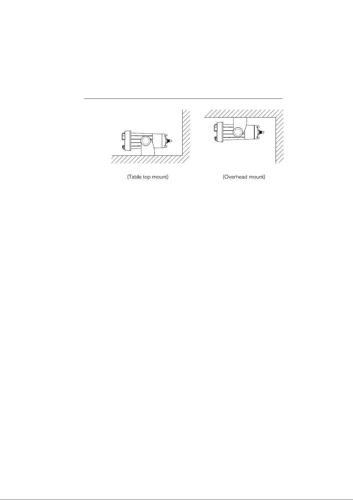
2.3.1 Typical Mounting Methods
The RAY215E can be conveniently mounted on a chart table, bulkhead,
overhead, or any other desired location. Refer to Figure 2-1 for typical
mounting methods.
CAUTION
Make sure there are no hidden electrical wires or other items behind
the desired location before proceeding. Check that free access for
mounting and cabling is available.
Page 16
Installation
2-3
Figure 2-1 Typical Mounting Methods
2.3.2 Flush Mounting
In addition to the typical Mounting Methods, the RAY215E may also be
flush mounted using the optional Flush Mount Kit. These kits are available
from your Raymarine dealer or our Customer Service Department.
There are two methods of mounting the radio using the flush mount kit:
from the front or rear of the console. Choose the method that best suits
your console.
1. Select the location for the radio transceiver. A clear, flat area, of
sufficient height having at least 9" of clear depth behind the panel is
required.
CAUTION
Make sure there are no hidden electrical wires or other items behind
the desired location before proceeding. Check that free access for
mounting and cabling is available.
2. Unpack the Flush Mount kit and confirm that all hardware is present.
3. Mark the cutout area using the cutout guide.
4. Drill a pilot hole inside of the cutout guide area.
5. Using an appropriate saw, carefully cut along the cutout line.
6. Remove the yoke knobs and the mounting yoke from the transceiver.
Check that the radio will fit into the cutout area.
Front Mounting
7. Insert the rear of the transceiver through the flush mount bracket such
that the tabs on the bracket point away from the radio’s front bezel.
Page 17

2-4 Installation
8. Continue to push the bracket onto the transceiver until it is flush with
the front bezel.
9. On each side of the transceiver, insert a screw through the bracket tab
and into the threaded holes from which you removed the yoke knobs.
10.Tighten the screws.
11.It is recommended to run a bead of RTV or similar sealant around the
inside edge of the bracket to avoid water entry behind the console.
12.Insert the radio and attached bracket into the cutout.
13.Install four flat head screws through the four countersunk holes in the
front of the bracket and secure into the console.
14. From behind the console, connect the power/optional speaker and
antenna cables.
Rear Mounting
7. It is recommended to run a bead of RT V or similar sealant around the
inside edge of the bezel to avoid water entry behind the console.
8. Insert the radio into the cutout until the front bezel is flush with the
console.
9. From behind the console, push the flush mount bracket over the rear
of the transceiver such that the tabs on the bracket point away from
the radio’s front bezel.
10.Continue to push the bracket onto the transceiver until it is flush with
the console.
11.On each side of the transceiver , insert a screw through the bracket tab
and into the threaded holes from which you removed the yoke knobs
but do not fully tighten at this time.
12. Install four pan head screws through the four holes in the bracket and
secure the bracket into the console.
13. From the front, make sure the transceiver is still flush with the console.
14. From behind the console, fully tighten the screws that secure the bracket
to the radio’s threaded yoke knob holes.
15.Connect the power/optional speaker and antenna cables.
Page 18
Installation
25 (1)
140 (5.51)
2-5
195 (7.68)
223 (8.78)
106 (4.17)
9 (0.35)
9 (0.35)
80 (3.15)
139 (5.47)
170 (6.69)
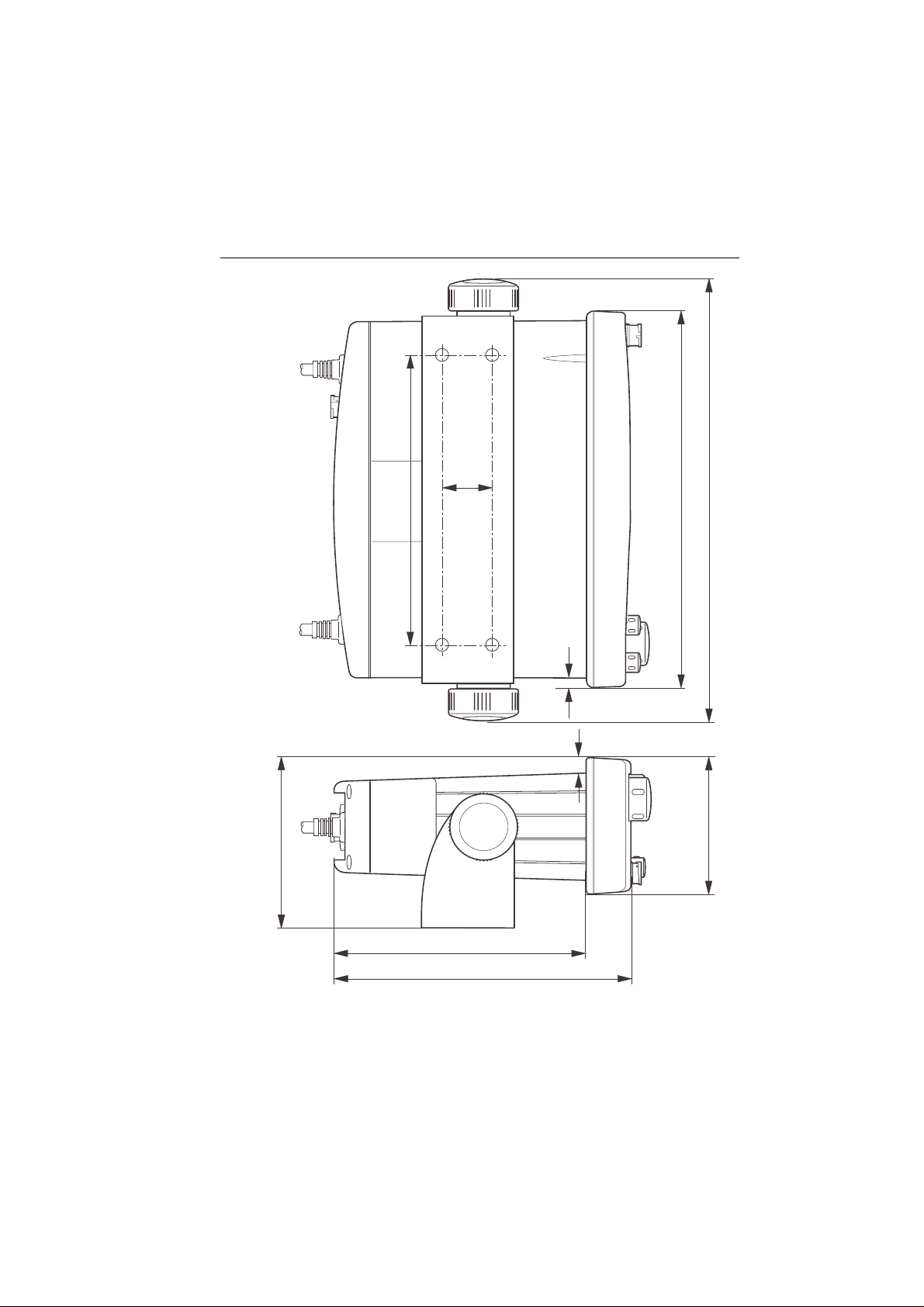
Figure 2-2 Outline and Mounting Dimensions
All dimensions are shown in millimeters and (inches)
Page 19
2-6 Installation
2.4 Electrical Connections
2.4.1 DC Power and External Speaker
Connections
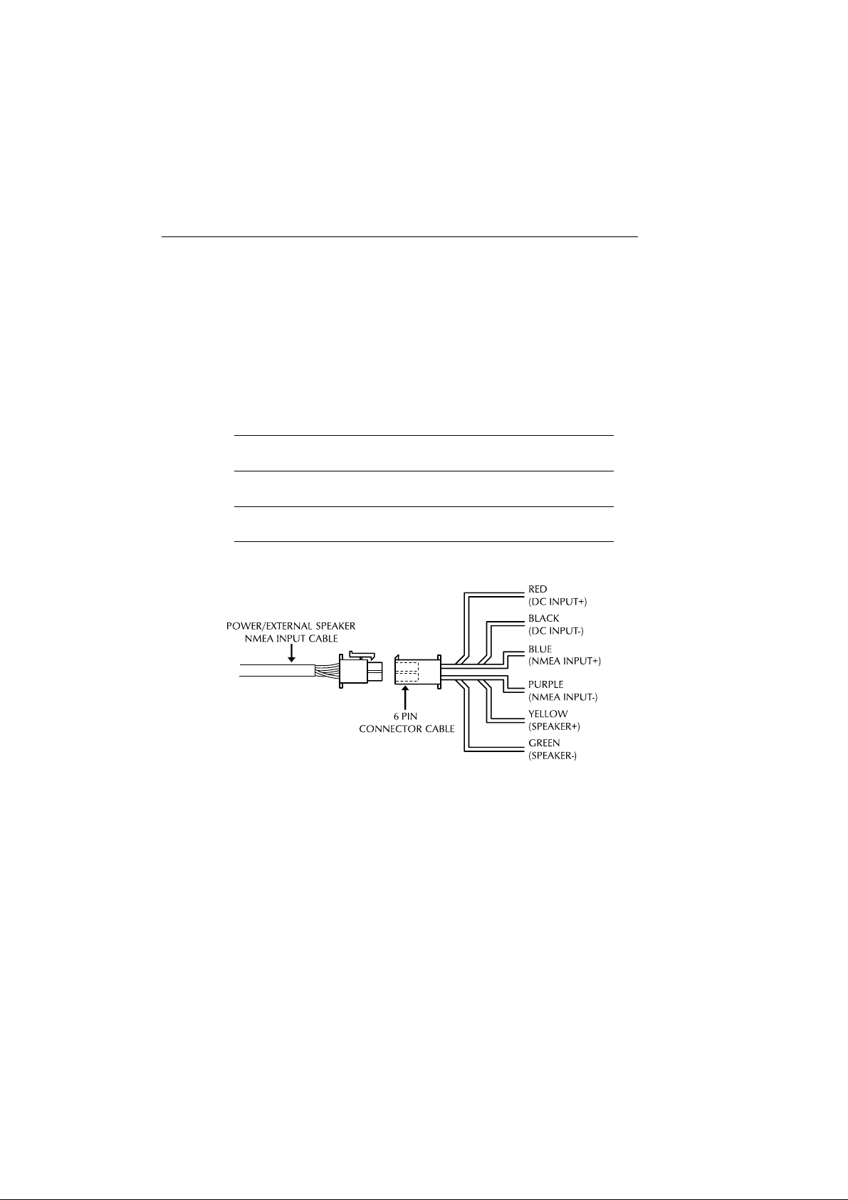
The 6-foot long power cable is a multi-purpose assembly containing three
wire-pairs for connections to DC power, NMEA input, and an optional
speaker. Connections to the 6-pin connector are as follows:
Wire ColorWire Color
Wire Color
Wire ColorWire Color
RED Power + Ship's 13.6 VDC power
BLACK Power −
YELLOW Speaker + External speaker
GREEN Speaker −
BLUE NMEA + Input from position source (GPS, etc.)
PURPLE NMEA −
The RED (+) power wire contains a 10 amp in-line fuse.
Figure 2-3 Power/External Speaker/NMEA Cable and 6 Pin Connector
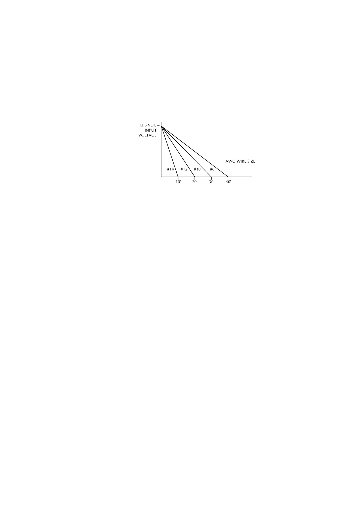
In most cases the length of the power cable should be adequate enough to
reach the DC power source. If additional wire length is required, the cable
can be extended by adding more cable as necessary . However, for power
cable runs longer than 15 feet, larger wire diameter size should be used to
prevent voltage line loss.
FunctionFunction
Function
FunctionFunction
Connects toConnects to
Connects to
Connects toConnects to
Your RAY215E should be connected to the nearest primary source of ship's
DC power. A typical source may be a circuit breaker on the power panel or a
fuse block near the unit. When connecting to either of these sources, the
circuit breaker or other in-line fuse should be rated at 10 amps.
Page 20
Installation
2-7
Figure 2-4 Power Cable Length
It is recommended that lugs be used to connect the power cable to the DC
supply and the lug connections should be both crimped and soldered.
This is very important in order to ensure adequate current draw to the
equipment. Intermittent operation may result if an insufficient connection
is made to the power source. The connection terminal should be clean,
with no sign of corrosion.
The red (+) wire is connected to the positive terminal of the power source.
The black (-) wire is connected to the negative (ground) of the power
source. Should the power connections be inadvertently reversed, the unit
will not power up but no damage will occur. Check the polarity with a
VOM (Voltage/Ohm Meter) and reconnect observing correct polarity. If
the fuse ever needs replacement, be sure to use the same type and rating.
2.4.2 External Speaker Connections
The yellow (+) wire and green (-) wire are used for connecting the
RAY215E to an external speaker (see Figure 2-3), such as Raymarine’s
10W External Speaker (part number E46006).
Four watts of audio output power are provided for an external 4-ohm
speaker. A suitable speaker can be purchased from your local marine dealer .
Connect the yellow (+) wire and green (-) wire to the speaker observing
polarity as it is marked on the speaker. When connected, the external
speaker will function simultaneously with the internal speaker.
CAUTION: DO NOT short the green (-) wire to the yellow (+) wire.
DO NOT short the green (-) wire to the black Power (-) wire.
Page 21
2-8 Installation
2.4.3 NMEA Data (Requires Full Function Handset)
When an optional Full Function Handset is installed enabling Class “D”
DSC functionality, inputting NMEA data will provide position information
to the radio. The RAY215E accepts NMEA 0183 data from a position
determining device (GPS, etc.) to provide the Latitude and Longitude
position information that is transmitted during a DSC Distress Call.
When the Full Function Handset is present but no valid NMEA signal is
detected, the NMEA indicator flashes continuously.
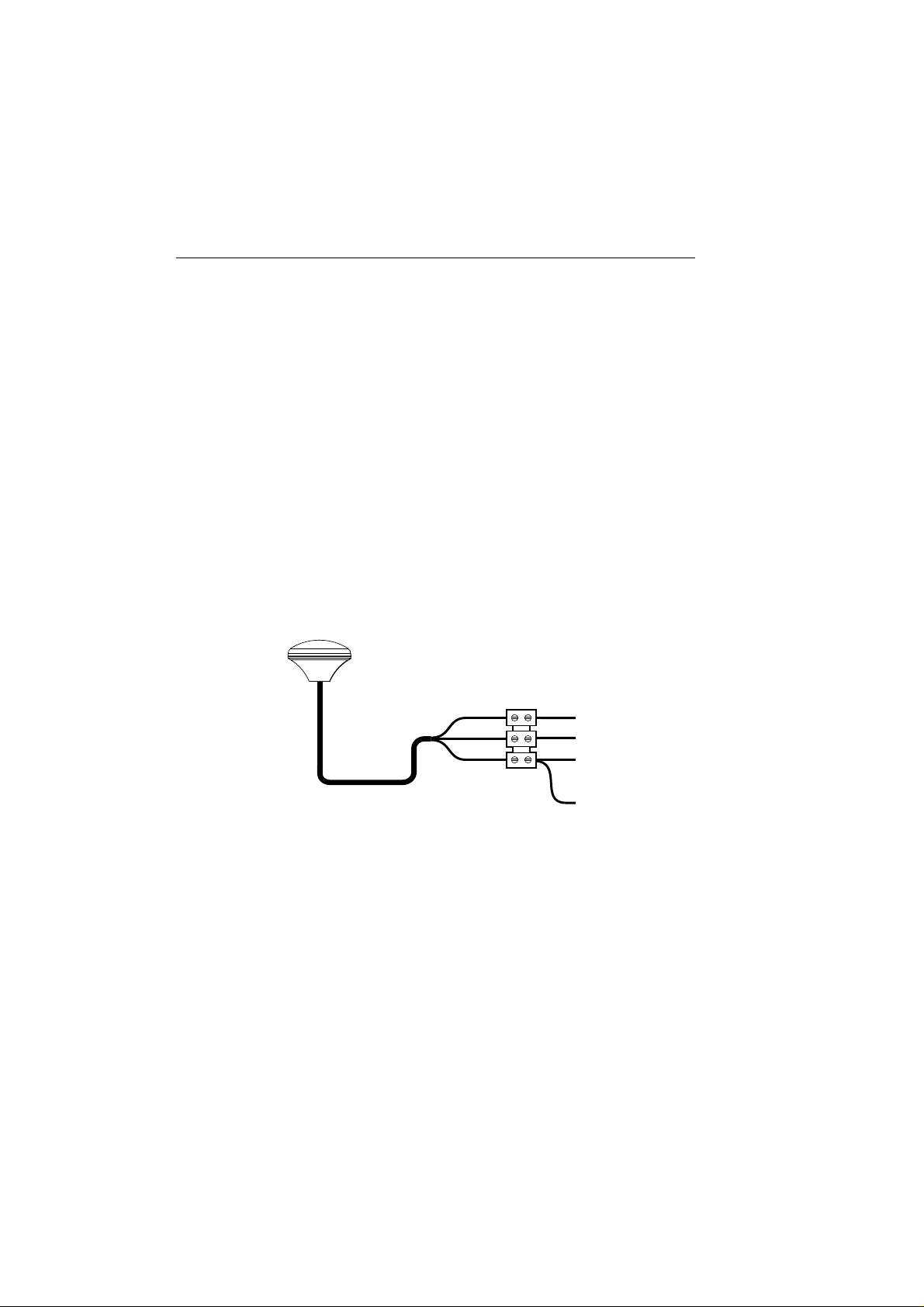
Connect the input(s) of the positioning device to the blue (NMEA+) and
purple (NMEA-) wires in the Power/Optional Speaker/NMEA cable.
An example of how to connect the NMEA cables and power supply using
a suitable connector block is shown in the diagram below. For specific
instructions how to connect your particular GPS, please refer to the
handbook that came with that device.
Note: For non-differential GPS, all return connections (-) must be tied to
a common ground reference.
Red
Yellow
Black
+12 V
+ NMEA Data (blue)
-- NMEA Data (purple)
0V
Figure 2-5 GPS Connections
2.4.4 Antenna Connections
The coaxial VHF antenna cable connects to the RAY215E antenna cable
on the rear panel using a PL259 VHF type connector. The antenna cable
length can be critical to performance. If you are uncertain, contact a
professional installer or call Raymarine Product Support. If a longer cable
length is required, RG-58 (50 ohm) coaxial cable or equivalent cable can
be used for runs up to a maximum of 50 feet. If the distance required is
even greater, Raymarine recommends using low loss RG-213 or equivalent
cable for the entire run to avoid excessive losses in power output.
Page 22

Installation
2-9
If the antenna RF connector is likely to be exposed to the marine
environment, a protective coating of grease (Dow Corning DC-4 or similar)
can be applied to the connector before connecting it to the radio. Any
other extensions or adapters in the cable run should also be protected by
silicon grease and then wrapped with a waterproofing tape.
2.4.5 Antenna Mounting Suggestions
The best radio in the world is useless without a quality antenna and good
location. Mounting the VHF antenna properly is very important because
it will directly affect the performance of your VHF radio. A VHF antenna
designed for marine vessels should be used.
• Since VHF transmission is essentially Line-of-Sight, mount the antenna
at the highest possible location on the vessel and free of obstruction to
obtain maximum range.
• If you must extend the length of the coaxial cable between the antenna
and the radio, use a coaxial cable designed for the least amount of power
loss over the entire cable length.
• Remember to maintain the recommended minimum 3 feet between the
radio and antenna.
2.4.6 Grounding
While special grounding is not generally required for VHF radiotelephone
installations, it is good marine practice to properly ground all electronic
equipment to the ship's earth ground system. The RAY215E can be
connected to ground by attaching a wire to one of the screws on the unit's
rear panel and then to the nearest ship's earth ground connection point.
The recommended wire to be used for such grounding is #10 AWG.
Page 23
2-10 Installation
Figure 2-6 Typical Grounding Method
Page 24

Operation with Minimum Function Handset
Section 3 Operation with
Minimum Function Handset
3.1 Introduction
The RAY215E can be operated with the standard Minimum Function
Handset, or an optional Full Function Handset that enables additional
features, or both handsets to enable intercom capabilities. This section
describes using the RAY215E with the Minimum Function Handset. See
Section 4 for a full discussion of operation using the Full Function Handset.
3.1.1 DSC and NMEA Operation
The Full Function Handset enables Class “D” DSC operations and NMEA
(GPS) position data transmissions in the RAY215E. DSC functions
include: Individual, Group, All Ships, and Distress calls. To have DSC
and NMEA (GPS) position functionality available with a Minimum
Function Handset, you must also have installed a Second Station Full
Function Handset.
3.2 Minimum / Full Function Handset Priority
3-1
When both a Minimum Function Handset and Full Function Handset are
in use, only one can have priority to make a call. When the Full Function
Handset is out of its cradle, it has priority over the Minimum Function
Handset and the REMOTE indicator illuminates on the LCD of the base
station. When the Full Function Handset is in the cradle, the Minimum
Function Handset has priority and the REMOTE indicator extinguishes.
Overriding the Full Function Handset
In an emergency, the base station can override the Full Function Handset
to make a call even though the handset has priority (is off the cradle). To
override the handset, press and hold the DSC/PRI key on the base station.
The REMOTE indicator flashes and the base station regains priority
control. Make your call as usual using the Minimum Function Handset.
On the Full Function Handset, OVERRIDE appears on the dot matrix
display. In this mode, all keys are disabled on the handset except for
DISTRESS. The base station retains control until the DSC/PRI key is
again pressed and held.
Page 25
3-2 Operation with Minimum Function Handset
Note: The RAY215E is designed to have the base station as the priority
unit. You should install the base station and Minimum Function Handset
in the radio operation room or the location from which the ship is normally
navigated. If an optional second station Full Function Handset is also
installed, that handset is the one that should be installed in the remote
location.
3.3 Handset Connections
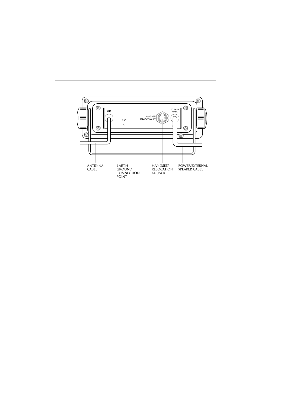
The Minimum Function Handset can be connected to the port on the front
of the base station (Figure 3-2) or mounted near the base station using the
optional Handset Relocation Kit (part number E46026), which is available
from your authorized Raymarine dealer/distributor. The Relocation Kit
must be connected to the HANDSET/RELOCATION KIT port on the
rear of the base station (Figure 3-1).
If both a Minimum Function Handset and Second Station Full Function
Handset are to be used, the Minimum Function Handset must be connected
to the front port with the Full Function Handset connected to the
HANDSET/RELOCA TION KIT port on the rear . In this case, the Handset
Relocation Kit could not be used with the Minimum Function Handset.
Once installed, the two stations can communicate with one another using
the Intercom function described in Section 4.6.14.
Figure 3-1 Rear Connections
Page 26
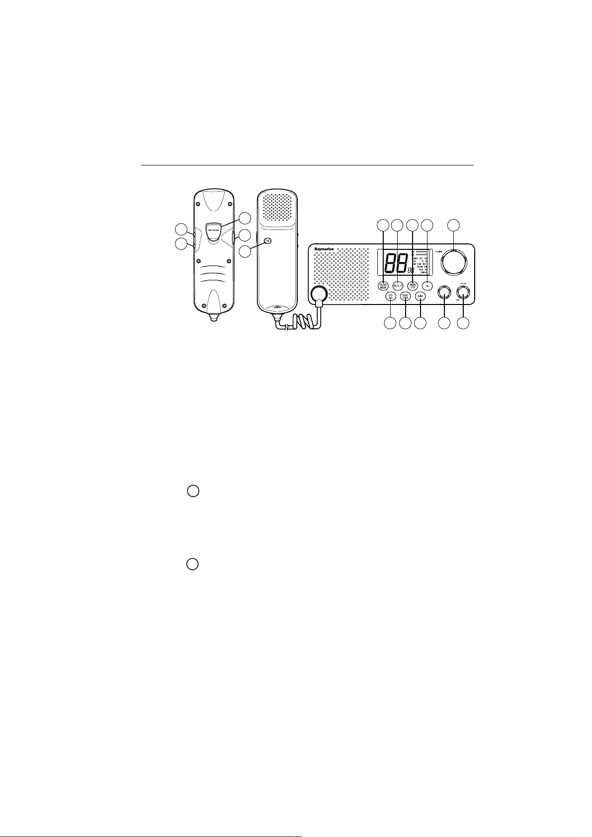
Operation with Minimum Function Handset
3-3
13
11
12
14
15
Figure 3-2 Layout of Controls
3.4 Control and LCD Display
3.4.1 Controls
Several of the keys on the front panel of the base station serve multiple
purposes. For the most part, the function indicated on the first line of
the key is accessed by pressing and releasing that key . The function
indicated on the second line of the key is accessed by pressing and
holding the key for two seconds.
CH (Channel Selection) Knob
This knob selects the active channel. Turning the knob clockwise
increments the channel number . Turning the knob counterclockwise
decrements the channel.
1
7654
231098
The knob is also used to select values and functions in DSC mode.
VOLUME/PWR Knob
This knob switches power on and off and controls the audio volume.
From the OFF position, rotating the knob clockwise until it “clicks”
powers ON the radio. Continuing to turn the knob clockwise, the
volume increases. Rotating the knob counterclockwise, the volume
decreases. Continuing to turn the knob counterclockwise, the unit
“clicks” OFF.
The upper bar graph on the LCD displays the volume level.
Page 27

3-4 Operation with Minimum Function Handset
SQUELCH Knob
!
This knob controls the squelch sensitivity level. Rotating the knob
clockwise increases the squelch level. Rotating the knob
counterclockwise decreases the squelch.
The lower bar graph on the LCD displays the squelch level.
SCAN/ MEM Key
"
This key starts or stops All Scan and Memory Scan Modes. The key
also places favorite channels into the radio’s memory for quick
selection.
Pressing and holding SCAN/MEM for 3 seconds stores into memory
the currently displayed channel and illuminates the MEM indicator
on the LCD. If the current channel has already been stored, pressing
SCAN/MEM removes the channel from memory and extinguishes
the MEM indicator.
Pressing and releasing SCAN/MEM when no channels have been
entered into memory initiates a scan of all available channels. The
SCAN indicator illuminates on the LCD.
When at least one channel has been programmed into memory,
pressing and releasing SCAN/MEM causes the MEM and SCAN
indicators to flash for 3 seconds. If the key is pressed again while
these indicators are flashing, the radio enters All Scan mode.
However, if the 3 seconds expire before pressing the key a second
time, the radio initiates a scan of only those channels programmed
into memory .
Pressing the SCAN/MEM key during All Scan or Memory Scan
terminates the scan.
MULTI Key
#
Pressing and releasing MULTI switches between the Multi-Call
channel and the last used marine channel. Pressing and releasing
MULTI while in the Dual Watch mode places the unit in Tri-Watch
mode. In Multi-Call mode, the MUL TI indicator illuminates solid on
the LCD. In Tri-Watch mode, the MULTI indicator flashes.
Pressing and holding MUL TI and SCAN/MEM key switches between
the International and US frequency groups, if your radio has been
upgraded to include US group channels.
Page 28

Operation with Minimum Function Handset
MON/ 1/25 Key
$
Pressing and releasing MON/1/25 initiates the Dual-Watch Monitor
mode.
Pressing and holding MON/1/25 for 2 seconds toggles the output
power between 1 and 25 watts. While in the 1 Watt mode, the 1W
indicator illuminates on the LCD.
In US mode only , pressing this key while holding PTT overrides the
1W output setting for channels 13 and 67.
16 Key
%
Pressing and releasing 16 switches the radio between the current
channel and the Priority Channel.
//
D/L
/ I . C . Ke y
&
//
Pressing and releasing D/L / I.C. switches receiver sensitivity between
Distant (full) and Local (desensitized) modes.
While in the Local mode, the DESENS indicator is illuminated.
Holding D/L / I.C. for 2 seconds toggles on and off the Intercom
function between the handset on the base station and an optional
remote Full Function Handset. Press PTT to converse with the other
station.
3-5
DSC/ PRI Key
'
Pressing and releasing the DSC/PRI key by itself has no effect.
Pressing and releasing the DSC/PRI and D/L / I.C. keys
simultaneously places the radio in DSC mode, which is used to make
Individual Ship’s, All Ships, Group, and Distress Calls.
Note: An optional Full Function Handset must be installed to enable
the Class “D” DSC functionality.
Pressing and holding DSC/PRI for 2 consecutive seconds returns
priority control from an optional second station Full Function Handset
to the base station. This feature is for immediately taking radio
operation control from the second station in case of an emergency.
DIM Key
Pressing this key once starts Dimmer mode, which adjusts the
brightness of LCD’s backlight.
Each successive press of the DIM key switches the brightness from
Off, to Low, to Medium, to High, then back to Off.
Page 29
3-6 Operation with Minimum Function Handset
Channel UP Key
This key increments the channel number by 1 each time it is pressed.
If pressed and held, the channel increments at a rate of 10 channels
per second.
Channel DOWN Key
This key decrements the channel number by 1 each time it is pressed.
If pressed and held, the channel decrements at a rate of 10 channels
per second.
!
DISTRESS Key (under hinged door on rear of handset)
The DISTRESS key sends a DSC Distress Call when pressed and
held for 5 seconds. The DISTRESS key operates only when an
optional Second Station Full Function Handset (which enables
Class “D” DSC functionality) is also installed.
"
PTT Key
Pressing the PTT (Push To T alk) key enables the radio’s transmitter.
PTT key operation is disabled when the selected channel is a
disallowed channel.
The radio is equipped with a 5 minute timeout timer as a safety feature.
After the PTT has been held continuously for 5 minutes, transmission
is discontinued and an alarm sounded until PTT is released.
#
16 Key
Has the same function as the 16 key on the front panel controls.
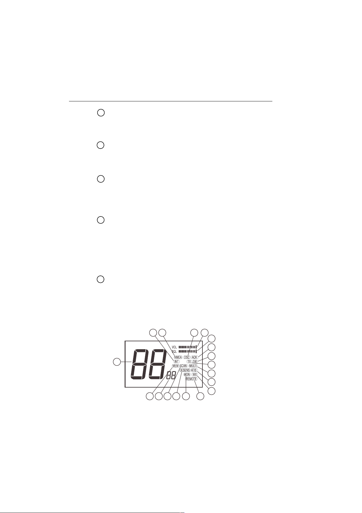
3.4.2 LCD Display
The following describes the functional characters on the RA Y215E’s LCD.
14
4 1
11
98
15
10
Figure 3-3 LCD Display Layout
162
17
3
7
6
5
18
12
13
Page 30

Operation with Minimum Function Handset
NMEA indicator
Appears in every operation mode when valid NMEA data is being
received (available only with optional Full Function Handset).
DSC indicator
Appears when the radio is in the DSC mode, when an optional Full
Function Handset is installed enabling the Class “D” DSC
functionality.
ACK indicator
!
Appears when receiving an acknowledgment to a DSC Distress Call
or Individual Call, when an optional Full Function Handset is installed
enabling the Class “D” DSC functionality.
INT indicator
"
Appears when the International frequency group is selected.
MULTI indicator
#
Appears when the radio is in the Multi-Call mode or a Multi-Call
channel is selected.
TX indicator
$
Appears during transmission.
1W indicator
%
Appears when the current transmission output is set at 1W.
(The indicator is extinguished when the output is set at 25W.)
3-7
MEM indicator
&
Appears when a channel on the display is stored in memory and
during a Memory Scan operation.
SCAN indicator
'
Appears during a scan operation.
DESENS indicator
Appears when the radio is in the Desensitized (local) mode.
MON indicator
Appears when the radio is in the Dual Watch or Tri-Watch Monitor
mode.
WX indicator (requires US Frequency Group upgrade)
Appears when the radio is in the Weather Channel or Tri-Watch
modes. (A vailable only in US Frequency mode when this option has
been installed.)
Page 31

3-8 Operation with Minimum Function Handset
REMOTE indicator
!
Appears when a remote Second Station Full Functional Handset
(optional) has the priority operation.
Channel display (Large)
"
Displays the current channel number.
Channel display (Small)
#
Displays the Priority Channel number while the radio is in the Monitor
mode and function indicators during DSC mode.
VOL indicator (in bar graph)
$
Represents the current sound volume level. A louder volume displays
a larger number of segments in the bar graph.
SQL indicator (in bar graph)
%
Represents the current squelch level. A deeper squelch displays a
larger number of segments in the bar graph.
ATIS indicator
&
Appears when the ATIS (automatic identification transmission)
feature is active.
3.5 Operating Procedures
3.5.1 Turning the Power On
Rotate the VOLUME/PWR knob clockwise to turn the radio on.
3.5.2 Setting the Squelch
Rotate the SQUELCH knob counterclockwise until audio is heard. Rotate
clockwise until noise “quiets”.
3.5.3 Setting the Volume
With audio present, rotate the VOLUME knob clockwise for the desired
volume level.
3.5.4 Setting the Power Output
Press the MON/1/25 key for two seconds to toggle between 1 watt output
and 25 watts output. When the 1W indicator is displayed, the output power
is 1 watt. If 1W is extinguished, 25 watts is being output.
The choice of power output is dependent upon the distance of transmission
and transmitting conditions. Some channels are fixed at the 1W setting.
Page 32

Operation with Minimum Function Handset
3.5.5 Setting the Channel
To select the appropriate channel, rotate the CH (Channel Select) Knob
clockwise/counterclockwise or use the Channel UP/DOWN keys on the
Minimum Function Handset.
3.5.6 Selecting the Private Channel
Ten Private Channels have been allocated for specific use within certain
countries. The following table lists the Private Channel designations in
each country and the corresponding RAY215E Private Channel numbers
(1–10). On the LCD, a dash (–) appears before private channels 0 through
9. For example, channel 2 appears as ‘- 2’.
PrivPriv
ateate
ate
ateate
..
.
..
ChannelChannel
Channel
ChannelChannel
DesignatorDesignator
Designator
DesignatorDesignator
Priv
PrivPriv
CountryCountry
Country
CountryCountry
UK - 1 M1/37C 157.850/157.850 Pleasure Boat
Denmark - 3 L1 155.500/155.500 Pleasure Boat
Finland, - 3 L1 155.500/155.500 Pleasure Boat
Norway & - 4 L2 155.525/155.525 Pleasure Boat
Sweden - 5 L3 155.650/155.650 Pleasure Boat
Netherlands - 6 31A 157.550/162.150
Belgium - 6 31A 157.550/162.150
Denmark, - 8 F1 155.625/155.625 Fishing Boat
Finland, - 9 F2 155.775/155.775 Fishing Boat
Norway & 10 F 3 155.825/155.825 Fishing Boat
Sweden
CH NoCH No
CH No
CH NoCH No
- 2 M2 161.425/161.425 Pleasure Boat
- 4 L2 155.525/155.525 Pleasure Boat
- 7 96D 162.425/162.425
FF
requencyrequency
F
requency
FF
requencyrequency
TX/RX (MHz)TX/RX (MHz)
TX/RX (MHz)
TX/RX (MHz)TX/RX (MHz)
ChannelChannel
Channel
ChannelChannel
UseUse
Use
UseUse
3-9
You must have the appropriate license and your RAY215E must be
programmed to use the private channel(s) that are approved for your
country.
Note: A license is required to operate the radio on the private channels.
It is your responsibility to obtain the proper license to operate the radio
on these frequencies.
Use of Private Channels requir es an upgrade from your dealer / distributor.
Page 33

3-10 Operation with Minimum Function Handset
To select the Private Channel:
1. Simultaneously press and release the SCAN/MEM and MON/1/25
keys. The assigned private channel number appears in the large channel
display. If multiple Private Channels are available, the first channel
number appears. “Pc” appears in the small channel display.
2. If multiple Private Channels are available, turn the CH knob until the
desired Private Channel number appears. The displayed Private
Channel number is selected.
Pressing SCAN/MEM initiates Scan mode, which includes the Private
Channel in the list of channels being scanned.
Pressing MUL TI initiates a T ri-Watch monitoring of the Private, Priority ,
and Working Channels. The Private Channel appears in the large channel
display, the Working Channel appears in the small channel display, and
the MON indicator flashes.
To exit the Private Channel, press the SCAN/MEM and MON/1/25 keys
again or press the 16 key to switch to the Priority Channel 16 .
3.5.7 Setting the Frequency Mode
The RAY215E can transmit and receive on all available International
marine VHF radiotelephone channels. With a software upgrade, the
RAY215E can also communicate on the US channel set.
If the US channel set option has been installed, pressing SCAN/MEM
and MULTI key simultaneously toggles between International and US
modes. When the International mode has been selected, the INT indicator
is illuminated. When the US mode has been selected, the INT indicator is
extinguished. There is no separate indicator for US mode.
Note: Some countries require special licensing to activate the US
channels.
3.5.8 Transmitting
Press the Push-To-Talk key (PTT) and speak into the microphone using a
clear normal voice. If the current channel is a TX prohibited channel, an
alarm will sound when PTT is pressed indicating such a transmission is
not permitted.
If the PTT key is pressed and held enabling the transmitter continuously
for 5 minutes, the RAY215E will automatically disable the transmitter.
Once PTT is released, the transmitter will be re-enabled.
Page 34

Operation with Minimum Function Handset
3.5.9 Selecting a Weather Channel (US Mode)
The US National Oceanic and Atmospheric Administration (NOAA)
broadcasts continuous weather reports and severe weather alerts, as needed.
The RAY215E can be set to receive these broadcasts if the unit has been
upgraded to use the US channel set, and US mode is selected. Weather
broadcasts can only be heard in the US and Canada.
To listen to weather broadcasts while in the US or Canada, press the
MUL TI key once to enter the Weather mode. Then use either the Channel
Select (CH) knob or Channel UP/DOWN keys on the Minimum Function
Handset to select the desired weather channel (0-9).
3.5.10 Priority Channel
Channel 16 is programmed as the Priority Channel. To switch from the
currently-used channel to the Priority Channel, press the 16 key once.When
the Priority Channel is active, a “P” appears in the small character display .
3.5.11 Channel Memory
The RA Y215E can store any International or US channel (if the optional
US channel set has been programmed). The stored channels are the ones
scanned in the Memory Scan mode.
3-11
To store a channel in memory, select the desired channel with the CH
knob and press and hold the SCAN/MEM key for 2 seconds. A tone sounds
and the MEM indicator is displayed. (W eather channels can not be stored
into memory).
To clear a channel from memory, select the memory channel and press
and hold the SCAN/MEM key for 2 seconds. The MEM indicator
extinguishes, indicating that channel is no longer stored in memory.
3.5.12 Resetting Factory Defaults
You can reset many radio settings back to their factory defaults:
• Erase any channels stored in memory for the Memory Scan function
• Erase any MMSI numbers stored for Individual Ship’s Call
• Turn OFF the backlight on both the base station and full function handset
• Return to INT channels, if US mode is selected
• Return the Weather Channel to channel 0, if US mode is selected
This will NOT erase the Own Ship’s MMSI ID number for your vessel
nor will it erase the PHNBOOK entries made with the Full Function
Handset.
Page 35

3-12 Operation with Minimum Function Handset
To perform the memory reset:
1. Turn the radio OFF.
2. Press and hold the SCAN/MEM key.
3. While continuing to hold the SCAN/MEM key, turn the radio ON.
The LCD remains blank for 2 seconds, CL appears momentarily , then
the unit switches to channel 16.
3.5.13 Scan Modes
The RAY215E is equipped with two types of scan options: All Scan and
Memory Scan. How these options are initiated depends upon whether
there are any channels stored in memory.
All Scan Mode
If no channels are stored in memory when the SCAN/MEM key is pressed,
the radio begins scanning all channels (except weather channels) as long
as no signal is received. If a signal is received, the scan stops on the
receiving channel as long as it is present. If the signal is lost for five
seconds or SCAN/MEM is pressed, the radio resumes scanning. SCAN
is displayed on the LCD while the Scan mode is active.
If the SCAN/MEM key is pressed again while SCAN is flashing, the All
Scan Standby state is suspended and the unit returns to the normal state.
To cancel the scan mode, press the SCAN/MEM key once.
Memory Scan Mode
If one or more channels are stored in memory when the SCAN/MEM key
is pressed, SCAN and MEM begin to flash simultaneously on the LCD. If
no other key is pressed within three seconds, SCAN and MEM stop
flashing and the radio begins scanning all channels currently stored in
memory. As with All Scan, if a signal is received, the scan stops on the
receiving channel until the signal is lost for five seconds or SCAN/MEM
is pressed, and then the radio resumes scanning. T o cancel memory scan,
press and release SCAN/MEM.
If there are channels stored in memory but All Scan operation is desired,
press SCAN/MEM again within the 3 second period while the SCAN and
MEM indicators are flashing.
Note: Scan modes are disabled when the ATIS operation is active.
Page 36

Operation with Minimum Function Handset
3.5.14 Monitor Mode
The RA Y215E is equipped with 2 types of monitor operations: Dual Watch
and Tri-Watch.
Note: Monitor modes are disabled when the ATIS operation is active.
Dual Watch Mode
Dual W atch monitors Channel 16 and either the selected Working Channel
or Private Channel. To initiate Dual Watch, first select the working or
private channel to be monitored, then press the MON/1/25 key once. The
selected W orking/Private channel and channel 16 are monitored for traf fic.
If a signal is received on the Working, Private, or Priority channel, the
radio monitors that channel as long as a signal is present. Dual Watch
resumes if the signal is lost for 7 seconds.
T o exit the Dual W atch mode, press MON/1/25 to return to the last Working
or Private channel, or press the 16 key to switch to the Priority Channel.
Tri-Watch Mode
When the RAY215E is in International mode, Tri-Watch monitors the
selected working channel, Channel 16, and the last used Multi-Call
channel. T o start T ri-Watch, initiate the Dual W atch mode, and then press
the MUL TI key. The MUL TI indicator illuminates on the LCD to indicate
the Multi-Call channel is also being monitored.
3-13
If the RAY215E has received an upgrade to use the US channel set, and
US mode is selected, Tri-Watch monitors the selected working channel,
Channel 16, and the last used Weather Channel for the Weather Alert
Tone. To initiate Tri-Watch, initiate the Dual Watch mode, and then press
the MUL TI key. The WX indicator illuminates on the LCD to indicate the
Weather Channel is also being monitored. Operation is the same as Dual
Watch except that if a Weather Alert Tone is received, the radio
simultaneously sounds an alarm tone, WX flashes, and the NOAA W eather
Alert is monitored. NOAA weather broadcasts can only be heard in the
US and Canada.
To exit the Tri-Watch mode, press MON/1/25 to return to the Working
Channel, or press MULTI to revert to Dual Watch mode, or press or the
16 key to switch to the Priority Channel.
Page 37

3-14 Operation with Minimum Function Handset
When the Private Channel is the active channel in International mode,
Tri-Watch monitors the selected Private Channel, Channel 16, and the
Working Channel last used before entering Private Channel mode. To
initiate Tri-Watch, press the MUL TI key once. You cannot enter Tri-W atch
from Dual Watch mode, as you do when the working channel is selected.
To exit Tri-Watch from Private Channel mode, press MULTI to return to
the Private Channel or press the 16 key to switch to the Priority Channel.
3.5.15 Multi-Call Operation
The Multi-Call function enables you to group all your frequently used
channels and store them in memory for quick access. You can store as
many Multi-Call channels as you would like.
Using Multi-Call
To start the Multi-Call operation, press the MULTI key. The last used
Multi-Call channel is displayed. Use the UP/DOWN key on the handset
or Channel Selection (CH) knob to increment/decrement through the MultiCall channels in memory .
When exiting Multi-Call, the last-used channel is stored to be used the
next time Multi-Call starts.
Changing from Multi-Call Channel to the Working Channel
Pressing the MULTI key toggles between the Multi-Call channel and the
last used marine working channel.
Storing a Multi-Call Channel
From the W orking or Private Channel mode, select the channel to be stored.
Press and hold MULTI key for 2 seconds. The MULTI indicator appears
when the registration is complete.
Deleting a Channel from Multi-Call
From the Working or Private Channel mode, select the channel to be
deleted. Press and hold the MUL TI key for 2 seconds. The MUL TI indicator
disappears when the channel has been deleted.
3.5.16 LCD Backlight Function
Pressing the DIM key adjusts the brightness of LCD’s backlight. Each
successive press of the DIM key switches the brightness from Off, to
Low, to Medium, to High, then back to Off.
Page 38

Operation with Minimum Function Handset
3.5.17 NMEA Operation
When an Optional Full Function Handset is installed enabling the Class
“D” DSC functionality , the RA Y215E can receive valid position and time
information, which are transmitted during a DSC Distress call. This data
can be communicated via NMEA 0183 from a GPS, fishfinder, radar, or
any device that outputs GPS sentences. If the radio does not detect the
position data, it provides alerts urging you to find and correct the fault.
The optional Full Function Handset enables you to manually input this
data using the L/L ENT function, as described in Section 4.7.3.2.
Note: NMEA position data can be communicated only when an optional
Single or Second Station Full Function Handset, enabling Class “D”
DSC functionality, has been installed.
If a GPS device is not connected via NMEA, the radio emits a 5-secondlong staccato alert tone and flashes the NMEA indicator 1 minute after
power up. This occurs every time the unit is turned on. The alarm is required
by safety regulations and cannot be disabled. However, the NMEA
indicator will not light nor will the alert tone sound if no Full Function
Handset is installed.
Operation at Power Up
At power up, the radio monitors the NMEA line for 1 minute. If a signal
is detected on NMEA, the radio determines whether the data is valid. If
valid, the data is accepted and the NMEA indicator is displayed on the
LCD.
3-15
If no GPS signal is detected on NMEA after the 1 minute monitoring
period, a 5-second-long staccato alert tone is emitted and the NMEA
indicator flashes. All the position fields are set to 9’s and the time and
date fields are set to 8’s.
If at a later time valid data is received on NMEA, the data is accepted and
the NMEA indicator is displayed solid (no longer flashing).
Operation When the Signal is Lost or Becomes Invalid
If positional data that was previously detected becomes invalid or is no
longer detected, the radio monitors the NMEA line for 1 minute for it to
be restored.
If a signal is restored on the NMEA line and the radio determines the data
is valid, the data is accepted and the NMEA indicator returns to a solid
state (not flashing).
Page 39

3-16 Operation with Minimum Function Handset
However, if no signal is detected, the NMEA indicator flashes and a 5second-long staccato alert tone is emitted. The NMEA indicator continues
to flash until valid positional data is received. If valid positional data
(from the same source) is later restored, the NMEA indicator is again
displayed solid.
Operation When No Signal Detected for 4 Hours
If no valid positional data is received or input manually using the Full
Function Handset within 4 hours of the previous alert, the NMEA indicator
continues to flash and the staccato alert tone is again emitted. This pattern
is repeated every 4 hours if no positional data has been detected. If no
manual input was made during the previous 23.5 hours, all the position
fields are set to 9’s and the time and date fields are set to 8’s.
3.5.18 Digital Selective Calling (DSC)
The Digital Selective Calling (DSC) protocol is a globally applied system
used to send and receive digital Distress calls as well as Individual and
All Ships calls on channel 70, the dedicated DSC channel for Marine
VHF. For a Distress call transmission, your RAY215E takes the position
and time information from the input NMEA data along with your Maritime
Mobile Station Identifier (MMSI) and converts it into a digital “packet”.
When transmitted, this digital information lets other ships and shore
stations equipped with appropriate DSC equipment know where you are
and that you are in a Distress situation.
In the RA Y215E, Class “D” DSC functionality is enabled by installing an
optional Full Function Handset. This can be in the form of Single Station
(Raymarine part number E46020) that replaces the Minimum Function
Handset or as a Dual Station (Raymarine part number E46022) that, when
used in conjunction with a Minimum Function Handset, enables intercom
functions between the two stations.
Note: DSC functions are enabled only when an optional Full Function
Handset has been installed. If no Full Function Handset is attached,
none of the following features will operate.
Communications in DSC mode include the following:
1. Transmitting/Receiving an Individual Call
2. Transmitting/Receiving an All Ships Call
3. Transmitting/Receiving a Distress Call (without designating type)
4. Receiving a Distress Relay Call (without designating type)
Page 40

Operation with Minimum Function Handset
Individual, All Ships and Group DSC calls come in three varieties:
ROUTINE for normal calls, SAFETY for advisory alerts, and URGENCY
for assistance when life is not in immediate danger. To enable DSC mode,
press and release the DSC/PRI and D/L / I.C. keys simultaneously. The
DSC indicator illuminates and a tone sounds. Since the Distress Call
(enabled by pressing and holding the Distress Key for 5 consecutive
seconds) automatically selects the DSC mode, it is not necessary to press
the DSC/PRI and D/L / I.C. to make a distress call.
When a DSC call is received, the radio automatically enters DSC mode if
you are currently on a selected working channel or private channel, in the
Monitor mode, or in the Scan mode.
Note: You must program the ship’s MMSI number before the radio can
enter the DSC mode. See section 3.5.18.1 below.
3.5.18.1 MMSI Number Setup on Base Station
You must enter your Maritime Mobile Service Identity (MMSI) number
in the RAY215E before the DSC system will be operational. You can
request an MMSI number when you apply for a radio license, if your
country allows you to enter an MMSI number yourself. Otherwise, your
authorized distributor or dealer can program the MMSI for you.
3-17
Note: Because it is required for enabling DSC functionality, a Second
Station Full Function Handset must be installed befor e you can program
in the MMSI number on the base station.
Once you have received your MMSI number, enter it into the radio as
follows:
1. Press and hold the DSC/PRI and D/L I.C. keys simultaneously for 2
seconds. A tone sounds and two dashes (- -) appear in the lar ge character
display.
2. Press and release SCAN/MEM key. The DSC indicator appears, “0”
is displayed in the large character display , and “1” is displayed in the
small character display.
Note: If an MMSI number is already in memory , the MMSI entry scrolls
across the display, one digit at a time.
3. Rotate the Channel Select (CH) knob until the first digit of your MMSI
number appears in the large character display. (Channel UP/DOWN
keys on the Minimum Function Handset are disabled during this
process).
Page 41

3-18 Operation with Minimum Function Handset
4. Press the DSC/PRI key once to accept. The small character display
now shows a “2”, designating the second digit in your MMSI number.
5. Rotate the Channel Select (CH) knob until the second digit of your
MMSI number appears in the large channel display.
6. Press the DSC/PRI key once to accept.
7. Enter all 9 digits of the MMSI number in the same way.
Once the 9th digit has been entered and accepted, the RA Y215E plays
back the 9 digits (one digit at a time) to verify proper entry.
Note: Ensur e the MMSI number entered is corr ect with this verification
playback. Once the number is accepted as outlined in the next step, it
cannot be changed except by Raymarine factory representatives.
8. If the number is verified as correct, press and hold the DSC/PRI key
for 2 seconds and a tone sounds. Your MMSI number has now been
stored in memory.
If the number is incorrect, press the DSC/PRI key once and release.
The radio will revert to the beginning of the entry process to start over
again. This step can be repeated as many times as required until the
number is entered correctly.
ROTATE
CH
Select desired digit
PRESS & REL
DSC
Continue thru last digit position
...through the 9th position
PRESS & HOLD
DSC + D/L
PRESS & REL
DSC
ROTATE
CH
PRESS & HOLD
DSC
PRESS & REL
DSC
Next digit position
Select desired digit
PRESS & REL
SCAN
MMSI digit
ROTATE
CH
Select desired digit
PRESS & REL
DSC
Radio replays all digits...
MMSI number accepted
Returns to working channel
digit position
Returns to first digit position
Page 42

Operation with Minimum Function Handset
3.5.18.2 Individual Ship’s Call
An Individual Ship’s Call is a DSC call made to a specific ship identified
by its MMSI number . There are three types: ROUTINE for normal calls,
SAFETY for advisory alerts, and URGENCY for assistance when life is
not in immediate danger.
The RA Y215E can receive all three types of Individual calls but can only
transmit ROUTINE Individual calls. As with any DSC operation, the call
is made on channel 70.
Sending an Individual Ship’s Call
The RA Y215E can only send a Routine Individual Call. The MMSI number
of the ship to which the Individual Call is to be sent can be input manually
or selected from a phonebook listing in memory. This section includes
instructions for using both methods and for adding numbers to the
phonebook.
Tip: You should first select the desired working channel before entering
the DSC mode to send an Individual Ship’s Call. That way, that channel
will already be displayed when the radio prompts for a working channel
after the MMSI has been selected.
Note: Only simplex channels (those which are transmitted and received
on the same frequencies) can be selected as the Individual Call working
channel. See the frequency list in Section 6 to see which channels are
simplex.
3-19
Using a manually input MMSI number
1. Press and release the DSC/PRI and D/L / I.C. keys simultaneously to
place the unit in DSC mode. “70” appears in the large channel display ,
the DSC indicator illuminates, and “in” appears in the small channel
display to designate individual call.
2. Press and release the DSC/PRI key. The DSC indicator appears, “0”
is displayed in the large character display , and “1” is displayed in the
small character display.
3. Rotate the Channel Select (CH) knob until the first digit of the other
ship’ s MMSI number appears in the large character display. (Channel
UP/DOWN keys on the handset are disabled during this process).
4. Press the DSC/PRI key once to accept. The small character display
now shows a “2”, designating the second digit in other ship’s MMSI
number.
Page 43

3-20 Operation with Minimum Function Handset
5. Rotate the Channel Select (CH) knob until the second digit of other
ship’s MMSI number appears in the large channel display.
6. Press the DSC/PRI key once to accept.
7. Enter all 9 digits of the MMSI number in the same way.
8. Once the 9th digit has been entered and accepted, the RA Y215E plays
back the 9 digits to verify the entry.
If the number is incorrect, press the DSC/PRI key once and release.
The radio will revert to the beginning of the entry process to start over
again. This step can be repeated as many times as required until the
number is entered correctly.
9. When the MMSI number is verified as correct, press and hold the
DSC/PRI key for 2 seconds to verify.
Note: The operation is cancelled if the 16 key is pressed or if no keys
are pressed for 60 seconds during any part of this process.
ROTATE
CH
Select desired digit
PRESS & REL
DSC
Continue thru last digit position
Radio replays all digits...
PRESS & REL
DSC + D/L
PRESS & REL
DSC
ROTATE
CH
Radio enters DSC mode
Next digit position
Select desired digit
...through the 9th position
PRESS & REL
DSC
MMSI digit
digit position
ROTATE
CH
Select desired digit
PRESS & RELEASE
DSC
Radio replays all digits through the 9th position
PRESS & RELEASE
DSC
PRESS & HOLD
DSC
Process starts over
MMSI number accepted
Page 44

Operation with Minimum Function Handset
PRESS & HOLD
DSC
ROTATE
CH
[TX] Flashing
PRESS & REL
DSC
Returns to last used channel
"ACK" signal received
from the specified ship
Standby for "ACK"
from specified ship
2 seconds after receiving ACK,
switches to selected channel
PRESS
PTT
Select desired working channel
10. After you have selected the other ship’s MMSI number, the radio
prompts you for the working channel you wish to communicate on.
The large character display shows the last used channel number and a
“W” appears in the small channel display. Use the Channel Select
knob to select the desired working channel for the Individual Call.
Note: Only simplex channels (those channels that transmit and receive
on the same frequency) can be selected for the working channel of an
Individual Call. Rotating the CH knob scrolls you through the simplex
channels usable for this operation.
11. Press the DSC/PRI key once. The TX indicator on the LCD flashes,
indicating the RAY215E is ready to transmit.
12.Press the PTT key to send the digital “packet” of information. The
radio waits for an acknowledgment from the targeted ship or station.
13. If the target station acknowledges, a tone sounds and “ACK”
illuminates on the LCD. After 2 seconds, the RAY215E switches to
the previously selected working channel.
or
If the call is not acknowledged, exit the DSC mode by pressing the 16
key.
3-21
Using an MMSI number selected from the phonebook:
Using the RAY215E with a Minimum Function Handset, you can select
from up to ten other ship’s MMSI numbers that have been stored in the
phonebook. The numbers are identified by a single letter that you have
assigned to it. Y ou must note what letter you assigned to the MMSI number
because only that letter appears on the LCD when you are retrieving it.
Note: The operation is cancelled if the 16 key is pr essed or if no keys ar e
pressed for 60 seconds during any part of this process.
Page 45

3-22 Operation with Minimum Function Handset
1. Press and release the DSC/PRI and D/L / I.C. keys simultaneously to
place the unit in DSC mode. “70” appears in the large channel display ,
the DSC indicator illuminates, and ”in” appears in the small channel
display to designate Individual Call.
2. Press and release the SCAN/MEM key. A letter appears in the small
channel display, which is associated with one of the other ship’ s MMSI
numbers in the phonebook.
3. If you wish to use the use the other ship’s MMSI number associated
with this letter, press DSC/PRI.
4. To use a different letter, rotate the Channel Selection Knob until the
desired letter is displayed. Press DSC/PRI to select this letter.
5. After you have selected the other ship’s MMSI number, the radio
prompts you for the working channel to communicate on. The large
character display shows the last used channel number and a “W”
appears in the small channel display.
6. Using the Channel Select (CH) knob on the front panel, select the
desired channel, and press the DSC/PRI key once. The TX indicator
on the LCD flashes, indicating the RAY215E is ready to transmit.
7. Press the PTT key to send the Individual Ship’s Call. After the digital
“packet” of information is sent, the radio waits for an acknowledgment
from the targeted ship or station.
8. If the target station acknowledges, a tone sounds and “ACK”
illuminates on the LCD. After 2 seconds, the RAY215E switches to
the previously selected working channel.
or
If the call is not acknowledged, exit the DSC mode by pressing 16
key.
Note: The operation is cancelled if the 16 key is pressed or if no keys
are pressed for 60 seconds during any part of this process.
Page 46

Operation with Minimum Function Handset
3-23
ROTATE
CH
Select letter assigned to desired MMSI
PRESS
DSC
[TX] Flashing
2 seconds after receiving ACK,
switches to selected channel
PRESS & REL
DSC + D/L
PRESS & REL
DSC
Returns to last used channel
PRESS
PTT
Standby for ACK from specified ship
Radio enters DSC mode
PRESS & REL
SCAN
ROTATE
CH
ACK received from specified ship
Select working channel
To store an MMSI number in phonebook:
1. Press and release the DSC/PRI and D/L / I.C. keys simultaneously to
place the unit in DSC mode. “70” appears in the large channel display ,
the DSC indicator illuminates, and “in” appears in the small channel
display to designate individual call.
2. Press and release the DSC/PRI key. The DSC indicator appears, “0”
is displayed in the large character display , and “1” is displayed in the
small character display.
3. Rotate the Channel Select (CH) knob until the first digit of your MMSI
number appears in the large character display. (Channel UP/DOWN
keys on the handset are disabled during this process).
4. Press the DSC/PRI key once to accept. The small character display
now shows a “2”, designating the second digit in your MMSI number.
5. Rotate the Channel Select (CH) knob until the second digit of your
MMSI number appears in the large channel display.
6. Press the DSC/PRI key once to accept.
Page 47

3-24 Operation with Minimum Function Handset
7. Enter all 9 digits of the MMSI number in the same way.
Note: The operation is cancelled if the 16 key is pressed or if no keys
are pressed for 60 seconds during any part of this process.
8. Once the 9th digit has been entered and accepted, the RA Y215E plays
back the 9 digits just entered for proper entry verification.
If the number is incorrect, press the DSC/PRI key once and release.
The radio will revert to the beginning of the entry process to start over
again. This step can be repeated as many times as required until the
number is entered correctly.
9. When the MMSI number is verified as correct, press the SCAN/MEM
key. A letter appears in the small channel display.
10.If you wish to assign this letter to the Other Ship’ s MMSI, press DSC/
PRI.
11. If you wish to assign a different letter to the Other Ship’s MMSI,
rotate the Channel Selection Knob until the desired letter is displayed.
12.Press DSC/PRI to store the MMSI number/letter assignment into the
phonebook.
Up to ten Other Ship’s numbers can be stored in the phonebook. The
letters available are as follows:
Y ou must note what letter you assigned to the MMSI number because
only that letter appears on the LCD when you are retrieving it.
Note: No data is stored in memor y when a wr ong key operation or an
interruption of power occurs during the entry procedure.
The operation is cancelled if the 16 key is pressed or if no keys are
pressed for 60 seconds during any part of this process.
To delete an MMSI number from the phonebook:
1. Press and release the DSC/PRI and D/L / I.C. keys simultaneously.
2. Press and release the SCAN/MEM key.
3. Rotate the Channel Selection Knob until the letter representing the
MMSI number to be deleted is displayed.
Page 48

Operation with Minimum Function Handset
4. Press and hold D/L/I.C. The selected number is deleted from the
phonebook and the radio switches to channel 16.
Receiving an Individual Ship’s Call
When an Individual Ship’s Call is received, the radio automatically enters
DSC mode if you are currently on a selected working channel or private
channel, in the Monitor mode, or in the Scan mode.
When receiving Individual Ship’s Call
1. If your station is targeted for an Individual Ship’s Call, a tone sounds
and the unit automatically switches to DSC mode. TX flashes on the
LCD and one of the following categories of Individual Ship’s Calls
flashes in the small number display:
“Ir” for ROUTINE Individual Ship’s Call
“IS” for SAFETY Individual Ship’s Call
“IU” for URGENCY Individual Ship’s Call
2. To acknowledge the incoming Individual Ship’s Call, press the PTT
key. The acknowledge is transmitted and your RA Y215E automatically
selects the working channel specified by the originating ship or station.
3. If you do not wish to acknowledge the call, press the 16 key to exit the
DSC mode.
3-25
Receive Individual Ship's Call:
Routine, Safety, or Urgency
PRESS & RELEASE
PTT
PRESS & RELEASE
16
Acknowleging the call
Not acknowleging the call
Page 49

3-26 Operation with Minimum Function Handset
3.5.18.3 All Ships Call
The All Ships Call is used to send out a message to all ships in range that
you need assistance but the situation is not serious enough for a Distress
Call. This call should only be used if hailing for assistance on channel 16
fails. There are three types of All Ships Calls: ROUTINE for normal calls,
SAFETY for advisory alerts, and URGENCY for assistance when life is
not in immediate danger. The RAY215E can receive all three types of
these calls but can transmit only SAFETY and URGENCY. As with any
DSC operation, the call is made on channel 70. Then, after the All Ships
Call is sent or received, the radio automatically selects channel 16.
Sending an All Ships Call
1. Press and release the DSC/PRI and D/L / I.C. keys simultaneously to
enter the DSC mode.
2. Rotate the Channel Select (CH) knob on the front panel to select the
desired type of call. The following appears in the small channel display:
“AS” for SAFETY All Ships Call
“AU” for URGENCY All Ships Call
3. Press and release the DSC/PRI key and TX begins to flash.
4. Press the PTT key to transmit the All Ships Call. The radio switches to
Channel 16.
5. Any station responding to your call converses on Channel 16.
ROTATE
CH
PRESS & REL
DSC + D/L
PRESS & REL
DSC
ROTATE
CH
PRESS & REL
PTT
Receiving an All Ships Call
If you are currently on a selected working channel or private channel, in
the Monitor mode, or in the Scan mode, the radio automatically enters
DSC mode when an All Ships Call is received. The type of call is displayed
in the small channel display and an alarm is sounded.
Page 50

Operation with Minimum Function Handset
Press the DSC/PRI key once and the radio automatically selects channel
16. There is no acknowledge required for an All Ships Call. If you do not
wish to accept the call, press the 16 key to exit the DSC mode.
Receive All Ships Call:
Routine, Safety, or Urgency
3.5.18.4 Group Call
The Group Call feature sends transmissions that are only received by
radios that share a common Group MMSI number.
The RA Y215E requires a Full Function Handset to program in the Group
MMSI number. For this reason, the Minimum Function Handset can only
receive Group Calls. You must use the Full Function Handset to send a
Group Call.
If you are currently on a selected working channel or private channel, in
the Monitor mode, or in the Scan mode when a Group Call is received,
the radio automatically enters DSC mode, sounds an alarm, and displays
the type of call.
PRESS & RELEASE
DSC
3-27
Converse on channel 16
After receiving a Group Call, press and release the DSC key to accept the
call. The unit switches to the working channel and extinguishes the DSC
indicator, indicating the unit has exited the DSC mode.
The large channel display indicates the working channel and the small
channel display is extinguished. If you do not wish to acknowledge the
call, press the 16 key to exit the DSC mode.
PRESS & RELEASE
DSC
Receive Group Call
Call accepted. Converse on
selected Working Channel.
Page 51

3-28 Operation with Minimum Function Handset
3.5.18.5 Distress Call
A Distress Call allows you to send out a digital “packet” of data at high
power that includes your position, time, and MMSI number. All ships and
stations outfitted with the correct type of DSC equipment will be able to
pinpoint your position and either relay the information or respond directly .
Using the Distress key overrides all other functions.
Note: DSC functions are enabled only when an optional Full Function
Handset has been installed. If no Second Station Full Function Handset
is attached, the Distress key on the Minimum Function Handset will not
operate.
Sending a Distress Call
1. On the back of the handset, lift the door marked DISTRESS.
2. Press and hold the red Distress key for 5 seconds. After 1 second, the
LCD displays a countdown from four to zero, beeping every second.
3. When the countdown has completed, the radio enters the DSC mode
and sends the digital information at high power. Once transmitted, the
radio monitors channel 70 for a Distress acknowledge but also monitors
channel 16 for emergency traffic.
Note: When a Distress Call is sent, the unit emits a VER Y LOUD distr ess
alarm tone. To mute the alarm without interr upting the Distress Call,
press the DSC/PRI key on the RA Y215E base station. The radio will remain
in DSC mode.
4. The Distress Call is automatically re-transmitted every 3.5 to 4 minutes
as long as you remain in the DSC mode. The radio continues to transmit
until either an acknowledge is received or the DSC mode is manually
exited by pressing the 16 key. The ACK indicator flashes, indicating
the radio is monitoring for an acknowledge.
5. If a receiving station has Distress acknowledge capability and sends
an acknowledge to you, the DSC tone sounds and the ACK indicator
appears solid for 1 second. Next, the radio exits the DSC mode and
switches to channel 16 for voice communications.
Page 52

Operation with Minimum Function Handset
PRESS & HOLD
DISTRESS
Waiting for Acknowledge
Switches to Channel 16
PRESS & HOLD
DISTRESS
After 1 sec, countdown begins
Distress call transmitted
Hold DISTRESS for full 5 seconds
Acknowledge signal received
Receiving a Distress Call
When a DSC Distress call is received, the radio automatically enters DSC
mode if you are currently on a selected working channel or private channel,
in the Monitor mode, or in the Scan mode. You will not receive a DSC
call if the radio is transmitting or receiving a non-DSC call.
3-29
1. When receiving a calling signal, the unit sounds the DSC tone and
enters the DSC mode. A “d” flashes in the small channel display for
Distress.
2. Press the DSC/PRI key. The radio accepts the call, silences the alarm,
and switches to channel 16.
Note: When a Distress Call is received, the unit emits a VERY LOUD
distress alarm tone. Pr essing the DSC/PRI key mutes this alarm but does
NOT cancel the Distress Call.
3. Because it is Class “D” DSC compliant, the RAY215E can receive a
DSC Distress Call but cannot acknowledge or relay the call. After the
Distress Call is received, attempt to contact the vessel in distress on
channel 16 and render assistance.
PRESS & RELEASE
DSC
Distress Call received
Switch to Channel 16
Page 53

3-30 Operation with Minimum Function Handset
3.5.18.6 Distress Relay Call
Sometimes a ship’s distress call can be relayed from another ship or a
shore station. Because it is Class “D” DSC compliant, the RAY215E can
receive a Distress Relay Call but cannot acknowledge or relay the call.
If the radio is active on a working channel or private channel, in the Monitor
mode, or in the Scan mode when a Distress Relay Call is received, the
unit automatically enters DSC mode and emits an alert tone. The DSC
indicator illuminates, 70 is indicated on the large channel display, and
“dr” flashes on the small channel display.
Press and release DSC/PRI. The unit switches to channel 16. “16” appears
as the working channel on the large channel display while the small channel
display is extinguished. The DSC indicator is also extinguished, indicating
the unit has exited the DSC mode.
The alert tone continues to sound until DSC/PRI is pressed to accept the
call or 16 key is pressed to exit the DSC mode.
You should attempt to contact the vessel in distress on channel 16 and
render assistance.
PRESS & RELEASE
DSC
Distress Relay Call received
Switch to Channel 16
3.5.19 ATIS ID No. Entry
The Automatic Transmission Identification System (ATIS) is used in some
European countries to identify vessels in their inland waterways. After
the PTT key is released following a transmission, the vessel’s ATIS ID
number is also transmitted.
Y ou must enter your A TIS ID number into the RAY215E before the ATIS
system will be operational. You can request an ATIS number when you
apply for a radio license.
Regulations in some regions may not allow end users to program their
own ATIS number . If this unit was purchased to be used in such a region,
this function will be disabled and the programming must be done by your
authorized Raymarine dealer/distributor .
Page 54

Operation with Minimum Function Handset
Notes:
1. After the ATIS ID number has been programmed, the ATIS function
will be active all the time, as per the European standard for a nonDSC radio. However, if you have installed a Full Function Handset,
which enables full Class “D” DSC functionality, the r egulation allows
for the disabling of ATIS. In the RA Y215E you can toggle A TIS on and
off by simultaneously pressing and releasing the SCAN/MEM and
D/L/I.C. keys .
2. While ATIS is active (the ATIS indicator is illuminated), the Scan and
Monitor functions are disabled. Also, certain channels are limited to
1 watt output power.
3. This is a one time operation. Once the ATIS number has been
programmed, you will not be able to change it without returning it to
your dealer/distributor for reprogramming.
After you have received your ATIS number, enter it into the radio as
follows:
1. Press and hold the DSC/PRI and D/L I.C. keys simultaneously for 2
seconds. A tone sounds and two dashes (- -) appear in the lar ge character
display.
2. Press and release MON/1/25 key. The ATIS indicator appears, “0” is
displayed in the large character display, and “1” is displayed in the
small character display.
Note: If an ATIS ID number is already in memory, the ATIS entry
scrolls across the display, one digit at a time.
3. Rotate the Channel Select (CH) knob until first digit of your ATIS ID
number appears in the large character display. (Channel UP/DOWN
keys on the handset are disabled during this process).
3-31
4. Press the DSC/PRI key once to accept. The small character display
now shows a “2”, designating the second digit in your ATIS ID number .
5. Rotate the Channel Select (CH) knob until the second digit of your
ATIS ID number appears in the large channel display.
6. Press the DSC/PRI key once to accept.
7. Enter all 9 digits of the ATIS ID number in the same way.
Once the 9th digit has been entered and accepted, the RAY215E will
playback the 9 digits (one digit at a time) to verify the entry.
Page 55

3-32 Operation with Minimum Function Handset
Note: Ensure the ATIS ID number entered is correct with the
verification playback. Once the number is accepted as outlined in the
next step, it can not be changed except by Raymarine repr esentatives.
8. If the number is verified as correct, press and hold the DSC key for 2
seconds and a tone sounds. Y our A TIS ID number has now been stored
in memory.
9. If the number is incorrect, press the DSC key once and release. The
radio will revert to the beginning of the entry precess start over again.
This step can be repeated as many times as required until the number
is entered correctly.
After the ATIS ID number has been programmed, the ATIS function will
be active all the time, unless you have a Full Function Handset installed.
With a Full Function Handset, the radio is upgraded to full Class “D”
DSC and, by law, the ATIS function may be toggled on and off. If a Full
Function Handset is installed, you can toggle the ATIS operation on and
off by pressing the SCAN and D/L/I.C keys simultaneously.
ROTATE
CH
Select desired digit
PRESS & REL
DSC
Continue thru last digit position
...through the 9th position
PRESS & HOLD
DSC + D/L
PRESS & REL
DSC
ROTATE
CH
PRESS & HOLD
DSC
Next digit position
Select desired digit
PRESS & REL
DSC
PRESS & REL
MON
ATIS digit
ROTATE
CH
Select desired digit
PRESS & REL
DSC
Radio replays all digits...
ATIS number accepted
Returns to working channel
digit position
Returns to first digit position
Page 56

Operation with Full Function Handset
Section 4 Operation with Optional
Full Function Handset
4.1 Introduction
The RAY215E can be operated with the standard Minimum Function
Handset, or an optional Full Function Handset that upgrades the radio to
full Class “D” DSC status, or both handsets to enable intercom capabilities.
This section describes using the RA Y215E with the optional Full Function
Handset. See section 3 for operation using the standard Minimum Function
Handset.
The Full Function Handset enables Class “D” DSC operations and NMEA
(GPS) position data transmissions in the RAY215E. DSC functions
include: Individual, Group, All Ships, and Distress calls. To have DSC
and NMEA (GPS) position functionality available on the RAY215E,
you must have a Full Function Handset installed.
The Full Function Handset also provides you with these additional features:
• Full alphanumeric keypad
• Dedicated keys for Individual and All Ships DSC calls
• DSC distress calls that describe the type of distress
• Send and receive DSC Group Calls
• Expanded ship and shore phonebooks for making DSC Individual calls
• Manually enter lat/lon and UTC time when GPS input is not available
• DSC call log
4-1
The Full Function Handset option is available as a Single Station
(Raymarine part number E46020) that replaces the Minimum Function
Handset or as a Second Station (Raymarine part number E46022) that,
when used in conjunction with a Minimum Function Handset, enables
intercom functions between the two stations.
4.2 Minimum / Full Function Handset Priority
When both a Minimum Function Handset and Full Function Handset are
in use, only one can have priority to make a call. When the Full Function
Handset is out of its cradle, it has priority over the Minimum Function
Handset and the REMOTE indicator illuminates on the LCD of the base
station. When the Full Function Handset is in the cradle, the Minimum
Function Handset has priority and the REMOTE indicator extinguishes.
Page 57

4-2 Operation with Full Function Handset
In an emergency, the base station can override the Full Function Handset
to make a call even though the handset has priority (is off the cradle). To
override the handset, press and hold the DSC/PRI key on the base station.
The REMOTE indicator flashes and the base station regains priority
control. Make your call as usual using the Minimum Function Handset.
On the Full Function Handset, OVERRIDE appears on the dot matrix
display. In this mode, all keys are disabled on the handset except for
DISTRESS. The base station retains control until the DSC/PRI key is
again pressed and held.
Note: The RAY215E is designed to have the base station as the priority
unit. You should install the base station in the radio operation room or
the location from which the ship is normally navigated. If a Second Station
Full Function Handset is also installed, that handset is the one that should
be installed in the remote location.
4.3 Handset Connections
The Full Function Handset connects to the port labeled HANDSET/
RELOCATION KIT on the rear of the base station (Figure 4-2). The Full
Function Handset will not operate if connected to the port on the front of
the base station.
If both a Minimum Function Handset and Second Station Full Function
Handset are to be used, the Minimum Function Handset must be connected
to the front port with the Full Function Handset connected to the
HANDSET/RELOCATION KIT port on the rear. Once installed, the two
stations can communicate with one another using the Intercom function
described in Section 4.6.14.
Figure 4-1 Rear Connections
Page 58

Operation with Full Function Handset
4.4 Controls and LCD Display
4-3
Figure 4-2 Layout of Controls
4.4.1 Controls
This section describes the control keys and display messages that appear
on the Full Function Handset.
Note: This Full Function Handset is also used with Raymarine radios
that have additional features. As a result, the yellow Function labels
POWER (16 key), CELL (3 key), HAIL (* key), and FOG (# key) r epresent
features that are not available on the RAY215E.
INDV key
Switches to the DSC Individual Ship’s Call mode for initiating
selective calls (ship-to-ship, group calls, etc.) using a specific MMSI
number. Descriptions of these operations follow.
Page 59

4-4 Operation with Full Function Handset
Note: An MMSI number is required to operate the DSC equipment
in this radio. You can program the MMSI number yourself using the
operation described in Section 4.7.4.2 (if regulations in your country
permit MMSI number programming by the radio owner) or you can
have your authorized Raymarine dealer/distributor program the
number for you.
ALL SHIP key
Switches to the All Ships Call mode for Safety and Urgency
transmissions. Descriptions of subsequent operations appear below
in Section 4.6.18.6 Transmitting All Ships Call.
VOL UP/DOWN key
!
Changes the sound volume of the handset. Pressing the UP
increases the volume, while the DOWN
∨∨
∨
key causes it to decrease.
∨∨
∧∧
∧
∧∧
key
The number of segments in the VOL bar graph on the LCD display
will increase or decrease accordingly. This setting does NOT affect
the volume of the base station or external speaker.
SQ UP/DOWN (SCROLL) key
"
Increases or decreases the squelch sensitivity. Pressing the UP
key increases the squelch, while the DOWN
∨∨
∨
key decreases it. The
∨∨
∧∧
∧
∧∧
number of segments in the SQ bar graph on the LCD display will
increase or decrease accordingly. This key is also used as a scroll
key for selecting menu items and other settings, as described below .
16 key
#
Switches between the Working or Private Channel and Channel 16
(the Priority Channel).
Note: The POWER label over this key does not pertain to the
RAY215E.
MON/TRI key
$
Starts the Dual-Watch monitor mode. Pressing the FUNC key
followed by the MON/TRI key initiates the T ri-W atch monitor mode.
1/MEM key
%
This key inputs the number 1. When an alphanumeric response is
appropriate, this key alternates between entering a 1 and a space. If
the channel number indicated on the LCD display is not currently
stored in memory, pressing the FUNC key followed by the 1/MEM
key enters that channel number into memory. If the currently indicated
channel has already been stored, pressing the FUNC key followed
by the 1/MEM key deletes that channel from memory .
Page 60

Operation with Full Function Handset
2/SCAN key
&
This key inputs the number 2. When an alphanumeric response is
appropriate, each press of this key alternately inputs the characters
2, A, B, then C. Pressing the FUNC key followed by the 2/SCAN
key toggles Scan mode ON or OFF.
3 key
'
This key inputs the number 3. When an alphanumeric response is
appropriate, each press of this key alternately inputs the characters
3, D, E, then F.
Note: The CELL label over this key does not pertain to the RAY215E.
4/US key
This key inputs the number 4. When an alphanumeric response is
appropriate, each press of this key alternately inputs the characters
4, G, H, then I. Pressing the FUNC key followed by the 4/US key
alternates the frequency groups between US and International mode
if US channels are enabled in your radio. If US channels are not
enabled, attempting to access this secondary function will result in
an alarm tone.
5/PRIV key
This key inputs the number 5. When an alphanumeric response is
appropriate, each press of this key alternately inputs the characters
5, J, K, then L. Pressing the FUNC key followed by the 5/PRIV key
switches to the Private Channel mode if Private Channels are enabled
in your radio. If Private Channels are not enabled, attempting to access
this secondary function will result in an alarm tone.
4-5
6/WX key
This key inputs the number 6. When an alphanumeric response is
appropriate, each press of this key alternately inputs the characters
6, M, N, then O. Pressing the FUNC key followed by the 6/WX key
alternates between the Working Channel and the Weather Channel.
This operation is valid only in US frequency mode.
7/ D/L key
!
This key inputs the number 7. When an alphanumeric response is
appropriate, each press of this key alternately inputs the characters
7, P , Q, R, then S. Pressing the FUNC key followed by 7/ D/L toggles
between full receiver sensitivity (distant mode) and attenuated
receiver sensitivity (local mode). Local mode is used in high traffic
areas to decrease unwanted reception. While in local mode (receiver
is desensitized), the DESENS indicator appears in the LCD display .
Page 61

4-6 Operation with Full Function Handset
"
8/M-CALL key
This key inputs the number 8. When an alphanumeric response is
appropriate, each press of this key alternately inputs the characters
8, T, U, then V. Pressing the FUNC key followed by the 8/M-CALL
key starts Multi-Call mode. If this key combination is pressed during
Multi-Call mode, the operation returns to normal mode.
9/ 1/25 key
#
This key inputs the number 9. When an alphanumeric response is
appropriate, each press of this key alternately inputs the characters
9, W, X, Y, and then Z. Pressing the FUNC key followed by the 9/ 1/
25 key alternates the transmission power between 1W and 25W.
$
* key
This key inputs an asterisk (*).
Note: The HAIL label over this key does not pertain to the RA Y215E.
%
0/IC key
This key inputs the number 0. Pressing the FUNC key followed by
the 0/IC key starts Intercom mode, which enables conversation
between the Minimum Function Handset connected to the port on
the front of the base station and a Full Function Handset connected
to the port on the rear of the base station. Pressing the FUNC key
followed by this key during Intercom mode returns operation to
normal mode.
&
# key
This key inputs the # character.
Note: The FOG label over this key does not pertain to the RAY215E.
ENT key
'
This key performs the Enter function. It is used to confirm and
implement an input action. Pressing the FUNC key followed by the
ENT/MENU key initiates the Menu mode.
CLR key
Depending on when it is used, this key exits the current mode and
reverts to the last used mode or normal operation. This key also can
be used to clear any alphanumeric inputs one at a time in the order
that they were entered. Pressing the FUNC key followed by CLR/
LOG key initiates the Digital Selective Calling (DSC) Log. Pressing
the key during logging returns operation to normal mode.
Page 62

Operation with Full Function Handset
FUNC key
Initiates the Function mode and activates the FUNC indicator in the
LCD display . The next key pressed determines the function selected.
(See above key descriptions.) Pressing this key twice starts Dimmer
mode, which reduces the brightness of LCD’s backlight.
Channel UP/ DOWN key
Pressing the CH UP (
channel number. Pressing the CH DOWN (
channel number.
PTT (Press-to-Talk) key
!
Pressing this key during normal operation places the radio in T ransmit
mode and displays the TX indicator in the LCD. When the key is
pressed in various function modes, the assigned operation is initiated.
Note: After 5 minutes of continuously holding the PTT key, the radio
will automatically stop transmitting. To begin transmitting again,
release the PTT and depress again.
DISTRESS key
"
This key is located under the small door labeled DISTRESS on the
back of the handset. Pressing and holding this key for 5 seconds
selects Distress Signal Call mode. Subsequent operations are
described in Section 4.6.18.8.
∧∧
∧
) key during normal operation increases the
∧∧
∨∨
∨
) key decreases the
∨∨
4-7
4.4.2 LCD Display
The following describes the functional characters on the RAY215E
Handset’s LCD.
Figure 4-3 LCD Display Layout
Page 63

4-8 Operation with Full Function Handset
NMEA indicator
Displayed when the radio receives valid NMEA position data. If the
data is invalid or no data is received for a period of time, the indicator
disappears.
FUNC indicator
Displayed when the FUNC key is pressed. Disappears when another
key is pressed, or after no other key is pressed for a period of time.
WX indicator
!
Displayed while in Weather Channel mode (optional US frequency
set only).
TX indicator
"
Displayed while transmitting.
US indicator
#
Displayed when the optional US frequency group is selected.
INT indicator
$
Displayed when the International frequency group is selected.
1W indicator
%
Displayed when the transmission power of 1W is selected with the
9/1/25 key or when a low power channel is selected.
DESENS indicator
&
Displayed during the desensitized receiving (local) mode.
MEM indicator
'
Displayed while the channel stored in memory is displayed. This
indicator flashes before the start of the memory scan operation.
MULTI indicator
Displayed while the channel stored in Multi-Call memory is displayed.
SCAN indicator
Displayed during Scan mode. If channels have been stored in memory ,
this indicator will be flashing before the start of Scan mode.
DSC indicator
Displayed when in a Digital Selective Calling (DSC) call mode, DSC
log, or the DSC menu.
ATIS indicator
!
Displayed when the ATIS (automatic identification transmission)
feature is enabled.
Page 64

Operation with Full Function Handset
"
VOL indicator (in bar graph)
Represents the current sound volume level of the handset. A louder
volume displays a larger number of segments in the bar graph. This
bar graph is not displayed during Menu mode.
#
SQL indicator (in bar graph)
Represents the current squelch level. A deeper squelch displays a
larger number of segments in the bar graph.
$
Three-digit, Seven-segment indicators
Display the channel number or state of the radio.
Nine-digit Dot-matrix display
%
Displays alphanumeric messages, modes, and functional status of
the radio.
4.5 Radio Functions
1. Selecting the Frequency Mode
Channel selection is available from among two frequency groups:
International and US (available only with a software upgrade).
2. Receiving the Weather Channels (Optional)
The RAY215E can programmed to receive 10 NOAA weather
channels and will sound an alarm if a W eather Alert is received. This
operation is available only in US frequency mode, if this option has
been activated in your unit. NOAA weather broadcasts can only be
heard in the US and Canada.
4-9
3. Private Channel Operation
If this feature is enabled in your radio, you can use the Private
Channels that have been allocated for specific use within certain
countries.
4. Dimmer Operation
Select from four LCD backlight levels, including OFF.
5. Monitor Operation
Select from Dual Watch or Tri-Watch mode.
6. Scan Operation
Select from All Scan or Memory Scan.
7. Selecting Transmission Power Output
Select either 1W or 25W for the transmission power.
Page 65

4-10 Operation with Full Function Handset
8. Digital Selective Calling (DSC) Operation
These functions include Individual Ships Call, All Ships Call, Distress
Call, Group Call, and DSC logging capability.
Note: An MMSI number is required to operate the DSC equipment
in this radio. You can program the MMSI number yourself one time
only , if permitted in your region, using the Menu Operation described
in Section 4.7.4.2 or you can have your Raymarine dealer program
the number for you.
9. NMEA Positional Data Reception
Positional information from external equipment is obtained using
the NMEA 0183 interface.
10. Remote Operation
When both a Minimum Function Handset and Full Function Handset
are connected, the RAY215E can be controlled by either handset.
When the Full Function Handset is out of its cradle, it has priority
over the Minimum Function Handset. When the Full Function
Handset is in the cradle, the Minimum Function Handset has priority
and BASE appears on the handset’s LCD.
If you need to make an emergency call with the Minimum Function
Handset while the Full Function Handset is out of the cradle, press
and hold the DSC/PRI key . The Minimum Function Handset regains
priority control and OVERRIDE appears on the Full Function
Handset’s LCD.
11. Intercom Function between Handsets
Intercom mode enables conversation between a Minimum Function
Handset connected to the front of the base station and a Second Station
Full Function Handset connected to the to the rear of the base station.
12. Reduced Receiving Sensitivity (Local Mode)
This function decreases receiver sensitivity in high traffic areas to
decrease unwanted reception.
4.6 Operating Procedures
With the Full Function Handset, all operations can be made on the Handset
except turning ON/OFF the base station and adjusting the sound volume
of the External Speaker.
Page 66

Operation with Full Function Handset
4.6.1 Setting the Volume
The sound volume adjustment for the handset has 11 settings. Pressing
and releasing the VOL UP (
pressing and releasing the VOL DOWN (
one level.
The number of segments in the VOL bar graph on the LCD display will
increase or decrease accordingly . If the VOL UP/DOWN keys are pressed
and held, the volume levels will automatically change every half-second.
Setting the Volume on the External Speaker (Second Stations only)
The volume knob on the External Speaker controls its sound volume. Turning
the knob clockwise increases the volume; turning it counterclockwise reduces
the volume. Turning the knob fully counterclockwise until you hear a “click”
switches off the speaker completely.
General alert tones will be sounded on the external speaker as long as it is
switched on. Received Distress or Urgency calls as well as the Weather
Alert Alarm will sound at maximum volume regardless of whether the
external speaker is switched on or off
Note: The external speaker is included with the Second Station Full
Function Handset kit but not the Single Station kit.
∧∧
∧
) key increases the volume by one level;
∧∧
∨∨
∨
) key reduces the volume by
∨∨
4-11
4.6.2 Setting the Squelch
The squelch adjustment enables you to “quiet” the receiver when no signal
is being received. The squelch adjustment for the handset has 11 settings.
Pressing and releasing the SQ UP (
level; pressing and releasing the SQ DOWN (
level. The number of segments in the SQ bar graph on the LCD display
will increase or decrease accordingly. If the SQ UP/DOWN keys are
pressed and held, the squelch levels will automatically change every halfsecond.
∧∧
∧
) key increases the squelch by one
∧∧
∨∨
∨
) key decreases it by one
∨∨
4.6.3 Using the Function Key
Most of the keys on the handset control secondary operations, indicated
by the label (in gold) above them. T o initiate the operation marked on the
label, press the FUNC key (also labeled in gold) followed by the key.
When the FUNC key is pressed, the FUNC indicator is displayed on the
LCD display. If no other key is pressed for 5 seconds, the Function
operation is cancelled and the FUNC indicator disappears.
Page 67

4-12 Operation with Full Function Handset
4.6.4 Setting the Frequency Mode
The RAY215E can transmit and receive on all available International
marine VHF radiotelephone channels. With a software upgrade, the
RAY215E can also communicate on the US channel set.
Indicators displayed in the LCD identify the active frequency group: US
for the US frequency group, or INT for the International group.
Pressing the FUNC key followed by the INT key alternates the frequency
groups from US mode to International mode then back to US mode. When
the radio is powered on, it starts on Channel 16 in the frequency group
last selected.
Note: Some countries require special licensing to activate the US
channels.
When the frequency group is changed, the channel number remains the
same as was selected in the previous group, as long as that number is
present in the new group. If a channel number is absent in the destination
group, the new channel will be the previous number plus 1. When returning
to the previous frequency group, the channel returns to its original number
if the channel has not been changed. If the channel has been changed, that
number is retained when the frequency group is changed.
Example 1
CH15 INT ⇒ CH15 US ⇒ CH15 INT
When shifting the frequency group, the channel remains the same because
the corresponding channel number exists in the new frequency group.
Example 2
CH2 INT ⇒ CH3 US ⇒ CH3 INT
No corresponding channel exists in the new frequency group, so the
channel is incremented by 1.
Example 3
CH2 INT ⇒ CH3 US, then changed to CH5 ⇒ CH5 INT ⇒ CH5 US
However, if the channel is changed in the new frequency group, this new
number is retained when the frequency group is changed.
Page 68

Operation with Full Function Handset
4.6.5 Receiving on the Weather Channels
The US National Oceanic and Atmospheric Administration (NOAA)
broadcasts continuous weather reports and severe weather alerts, as needed,
that can be received in the US and Canada. If your RAY215E has been
programmed to use the US channel set and the US mode is selected, you
will be able to receive these reports while your vessel is traveling in the
waters of the US or Canada.
Note: This feature requires software upgrades for access to the US
frequency group and to the weather channels. Weather channels can be
received only in the US frequency mode when the vessel is located in the
waters of the US or Canada. Some countries require special licensing to
activate the US channel set.
The Weather Channels consist of Channel 0 through Channel 9. These
are separate from the Channels in the regular frequencies set. To switch
between the Working Channel and the current Weather Channel, press
the FUNC key followed by the 6/WX key . While the Weather Channel is
active, the WX indicator appears in the LCD display and the frequency
group indicator disappears.
If the channel number is changed while in the Weather mode, the new
channel number is stored in memory upon exiting Weather mode. To exit
Weather Mode, press CLR, or FUNC followed by 6/WX.
4-13
4.6.6 Selecting the Channel
T wo methods are available for selecting the channel: inputting the channel
with the numeric keypad then pressing the ENT key , or using the Channel
UP/DOWN key on the side of the handset. Either method is applicable to
the International and US frequency modes.
Using the Channel UP/DOWN keys
Pressing the CH UP (
one for each keyclick. When the highest channel number is reached, the
channel scrolls to the lowest number and increments from there. Pressing
the CH DOWN (
for each keyclick. When the lowest channel number is reached, the channel
scrolls to the highest number and decrements from there. Channel numbers
not available in a frequency group are skipped.
If the CH UP/DOWN keys are pressed and held for at least a half second,
channels automatically change every 100 milliseconds.
∧∧
∧
) key increments the current channel number by
∧∧
∨∨
∨
) key decrements the current channel number by one
∨∨
Page 69

4-14 Operation with Full Function Handset
Using the Numeric Keypad
T o select a channel, input the desired number on the keypad. For 5 seconds
the channel number flashes on the LCD display . If the ENT key is pressed
during this 5 second interval, the channel change is implemented.
If the 5 seconds elapse without pressing another key , the channel change
is implemented anyway. If the CLR key is pressed while the number is
flashing, the channel returns to the previous number.
Note: A leading zero is required for single digit channel numbers.
4.6.7 Selecting the Private Channel
Ten Private Channels have been allocated for specific use within certain
countries. The following table lists the Private Channel designations in
each country and the corresponding RAY215E Private Channel numbers
P1–P10.
You must have the appropriate license and your RAY215E must be
programmed to use the private channel(s) that are approved for your
country.
Note: While using the Private Channel, selecting a new Working Channel
or pressing the CLR key returns operation to the Working Channel.
PrivPriv
ateate
ate
ateate
..
.
..
ChannelChannel
Channel
ChannelChannel
DesignatorDesignator
Designator
DesignatorDesignator
Priv
PrivPriv
CountryCountry
Country
CountryCountry
UK P1 M1/37C 157.850/157.850 Pleasure Boat
Denmark P3 L1 155.500/155.500 Pleasure Boat
Finland, P3 L1 155.500/155.500 Pleasure Boat
Norway & P4 L2 155.525/155.525 Pleasure Boat
Sweden P5 L3 155.650/155.650 Pleasure Boat
Netherlands P6 31A 157.550/162.150
Belgium P6 31A 157.550/162.150
Denmark, P8 F1 155.625/155.625 Fishing Boat
Finland, P9 F2 155.775/155.775 Fishing Boat
Norway & P10 F3 155.825/155.825 Fishing Boat
Sweden
CH NoCH No
CH No
CH NoCH No
P2 M2 161.425/161.425 Pleasure Boat
P4 L2 155.525/155.525 Pleasure Boat
P7 96D 162.425/162.425
FF
requencyrequency
F
requency
FF
requencyrequency
TX/RX (MHz)TX/RX (MHz)
TX/RX (MHz)
TX/RX (MHz)TX/RX (MHz)
ChannelChannel
Channel
ChannelChannel
UseUse
Use
UseUse
Page 70

Operation with Full Function Handset
Note: A license is required to operate the radio on the private channels.
It is your responsibility to obtain the proper license to operate the radio
on these frequencies.
To select the Private Channel:
1. Press the FUNC key, followed by the 5/PRIV key. The assigned private
channel number appears in the large channel display, preceded by a
“P”. If multiple Private Channels are available, the first channel number
appears.
2. If multiple Private Channels are available, press the CH up/down keys
until the desired Private Channel number appears. The displayed Private
Channel number is selected.
or
Input the private channel number on the keypad. For 5 seconds the
channel number flashes on the LCD display. If the ENT key is pressed
during this flashing phase or the 5 seconds elapse without pressing
another key , the channel is changed. If the CLR key is pressed during
the flashing phase or the number you have selected is not valid, the
channel returns to the previous number.
If Private Channels are not enabled, attempting to access this secondary
function will result in an alarm tone.
4-15
The Private Channel is included in the list of channels being scanned
during Scan mode.
4.6.8 Priority Channel
The Priority Channel operates on Channel 16. Pressing the 16 key during
any operation except the Distress Call switches to the Priority Channel.
While using the Priority Channel, pressing the 16 key returns operation to
the W orking Channel.
Page 71

4-16 Operation with Full Function Handset
4.6.9 Multi-Call Operation
The Multi-Call function stores as many channels as desired in memory
for quick access to frequently used channels.
Using Multi-Call
T o start the Multi-Call operation, press the FUNC key followed by the 8/
M-CALL key. The Multi-Call channel used in the previous operation is
displayed. Use the Channel UP/DOWN keys to increment/decrement
through the Multi-Call channels in memory. When exiting Multi-Call, the
last-used channel is stored to be used the next time Multi-Call starts.
Changing from the Multi-Call Channel to the Working Channel
During the Multi-Call operation you can return to the Working Channel
by again pressing FUNC followed by 8/M-CALL, by pressing the CLR
key , or by entering the channel number directly with the ENT key.
Storing the Multi-Call Channel
From the W orking or Private Channel mode, select the channel to be stored.
Press and release the FUNC key then press and hold the 8/M-CALL key
for 3 seconds. The MULTI indicator appears when the registration is
complete.
Deleting a Channel from Multi-Call
From the Working or Private Channel mode, select the channel to be
deleted. Press and release the FUNC key then press and hold the 8/MCALL key for 3 seconds. The MULTI indicator disappears when the
channel has been deleted.
4.6.10 Channel Memory
Channels that are stored in memory in the same group can be scanned
using the Memory Channel Scan function. Channels can be stored in
memory for each frequency group; when the frequency group is changed,
the radio operates according to the channels stored in memory for that
group.
Storage in memory of Weather Channels or Private Channels is disabled.
When storage of these channels is attempted, the registration is terminated
and an error alert tone sounds.
Storing Channels in Memory
From the Working Channel mode, select the channel to be stored. Press
the FUNC key followed by the 1/MEM key . The MEM indicator appears
when the registration is complete.
Page 72

Operation with Full Function Handset
Deleting Channels from Memory
From the Working Channel mode, select the channel to be deleted. Press
the FUNC key followed by the 1/MEM key. The MEM indicator disappears
when the channel is deleted.
4.6.11 Setting the Transmission Power Output
The transmission output can be set at either 1W or 25W. When the power
supply is switched on, the output is 25W . Pressing the FUNC key followed
by the 9/1/25 key alternates the transmission between 25W and 1W.
The choice of power output is dependent upon the distance of transmission
and transmitting conditions. Some channels are fixed at the 1W setting.
When 1W is selected, the 1W indicator is displayed on the LCD. When
25W is selected the 1W indicator disappears.
4.6.12 Desensitized Reception (Local Mode)
Y ou can set the RA Y215E to reduce the receiving sensitivity in high traf fic
areas to decrease unwanted reception. This is also known as local mode.
T o select this mode, press the FUNC key followed by the 7/D/L key . While
the desensitize function (local mode) is active, the DESENS indicator
appears in the LCD display. To return to full receiver sensitivity (distant
mode), again press the FUNC 7/D/L key combination.
4-17
4.6.13 LCD Backlight Function
LCD backlight brightness can be set at four different levels. Press the
FUNC/DIM key two times to enter Dimmer mode. Each successive click
of the FUNC/DIM key alternates the brightness from Off, to Low, to
Medium, to High, then back to Off. As the backlight setting is changed,
the dot matrix indicator displays the following messages: DIM OFF for
the Off setting, DIM LOW for Low, DIM MID for Medium, and DIM HI
for High.
When the ENT or CLR keys are pressed or when no other key operation
is made for 5 seconds, the current state is accepted and stored in memory ,
and the backlight setting operation is complete. The next time the power
supply is switched on, the state of the backlight is recalled and is applied
to each handset individually.
When selecting the DIM OFF setting or pressing any key while in DIM
OFF mode, the display is lit at the DIM LOW setting for 5 seconds and
then turned off. This is so you can view the display in low light conditions.
Page 73

4-18 Operation with Full Function Handset
4.6.14 Intercom Mode
Intercom mode enables conversation between a Minimum Function
Handset connected to the port on the front of the base station and a Full
Function Handset connected to the port on the rear of the base station.
Note: Using the Intercom is a simplex operation. You must press PTT to
talk to the other station and release PTT to listen.
Making a Call from the Full Function Handset
1. Press the FUNC key followed by the 0/IC key to enter Intercom mode.
IC appears on the large display. While calling, CALLING BASE
appears on the dot matrix display.
When the other station answers the call, the message CALLING turns
to CONNECT.
Note: If the other station does not r espond within 60 seconds, the unit
exits Intercom mode.
2. Press PTT to speak to the other station and release PTT to listen.
3. To exit Intercom mode, again press FUNC followed by 0/IC.
Making a Call from the Base Station
1. Press and hold the D/L/I.C. key to enter Intercom mode. IC appears
on the large channel display. While calling, REMOTE flashes on the
small channel display.
When the other station answers the call, REMOTE stops flashing and
appears solid.
Note: If the other station does not respond within 60 seconds, the unit
exits Intercom mode.
2. Press PTT to speak to the other station and release PTT to listen.
3. To exit Intercom mode, again press and hold the D/L/I.C. key.
Receiving a Call with the Full Function Handset
1. When an Intercom call is received, the handset speaker and external
handset speaker both emit a calling tone. If the handset is on the cradle,
the calling tone is not emitted from the handset speaker.
IC appears on the large display and CALL FROM BASE flashes on
the dot matrix display .
2. To answer the call, press PTT. The calling tone ceases and the dot
matrix display goes blank.
Note: If not answered within 60 seconds after being called, the call
terminates and the display returns to its previous state.
Page 74

Operation with Full Function Handset
3. Press PTT to speak to the other station and release PTT to listen.
4. To exit Intercom mode, again press FUNC followed by 0/IC.
Receiving a Call at the Base Station
1. When an Intercom call is received, the base station speaker emits a
calling tone. IC appears on the large channel display and REMOTE
flashes on the small channel display.
2. To answer the call, press PTT. The calling tone ceases and REMOTE
stops flashing and appears solid.
Note: If not answered within 60 seconds after being called, the call
terminates and the display returns to its previous state.
3. Press PTT to speak to the other station and release PTT to listen.
4. To exit Intercom mode, again press and hold the D/L/I.C. key.
4.6.15 Scan Mode
During Scan mode, the RA Y215E searches through the channels (including
Private Channels), stops when radio traffic is detected, then resumes
scanning after the traffic ceases. Two scan functions are available: All
Channel Scan and Memory Channel Scan. The All Channel Scan function
searches all channels within the same frequency group. The Memory
Channel Scan searches only the channels stored in memory in the same
group.
4-19
The scan begins from the channel following the one currently indicated.
The scan is suspended when a carrier is detected. Five seconds after the
carrier ceases, the scan resumes with the next channel. If the carrier is
detected again before 5 seconds elapse, the timer is re-initialized. Press
the 2/SCAN key to resume the scan from the next channel. Pressing FUNC
followed by 2/SCAN key or pressing the CLR key during the scan cancels
the scan.
Upon reaching Channel 88, the radio scrolls back to Channel 1 and
continues the scan. (If Private Channels have been enabled, they are
scanned following Channel 88.) If the scan stops on a channel with traffic
and you wish to communicate with the other party, press the PTT key to
cancel the scan and remain on that channel.
Note: Scan modes are disabled when the ATIS operation is active.
Entering a Channel into Memory:
Follow these steps to enter a channel into memory so it can be monitored
during memory scan.
Page 75

4-20 Operation with Full Function Handset
1. Use the Channel Selection (CH) keys or numeric keypad to select the
Working Channel or Private Channel you wish to enter into memory.
2.
Press the FUNC key followed by the 1/MEM key . The MEM indicator
illuminates, indicating that the channel is now in memory.
Using Memory Scan
This function is available only when at least one channel has been stored
in memory.
Press the FUNC key followed by the 2/SCAN key. The messages MEM
and SCAN flash for 3 seconds on the LCD. A scan of only the channels in
memory is initiated when the 3 seconds elapse or when you press the
ENT key before the 3 seconds elapse.
Pressing FUNC followed by 2/SCAN key or pressing the CLR key during
the scan cancels Memory Scan.
Using All Scan
Press the FUNC key followed by the 2/SCAN key The messages MEM
and SCAN flash for 3 seconds on the LCD. Before the 3 seconds elapse,
press the 2/SCAN key again to begin All Scan. If the 3 seconds elapse
before you press the 2/SCAN key, the radio will enter Memory Scan.
Pressing FUNC followed by 2/SCAN key or pressing the CLR key during
the scan cancels All Scan.
4.6.16 Monitor Mode
Monitor operation can be implemented in one of two modes: Dual-W atch
or Tri-Watch.
Note: Monitor modes are disabled when the ATIS operation is active.
Dual-Watch
In Dual-W atch Mode, the RAY215E operates on the Working Channel or
Private Channel while constantly monitoring the Priority Channel 16. The
radio locks onto the Priority, Working, or Private Channel whenever it
becomes active, then returns to Dual-Watch when there is no activity.
T o start Dual-W atch Mode, select the desired W orking Channel or Private
Channel, and then press the MON key. The Working Channel or Private
Channel is displayed on the 7-segment display and the Priority Channel
appears on the right side of the dot matrix display.
To end Dual-Watch mode at the current channel, press the MON key or
the CLR key .
Page 76

Operation with Full Function Handset
Tri-Watch
When the RAY215E is using the International frequency set, Tri-Watch
monitors the Working Channel or Private Channel, the Priority Channel
16, and the previously selected Multi-Call channel. When a signal is
detected on the Working, Private, Priority, or Multi-Call Channels, that
channel becomes active. When there is no longer any activity on the
channel, the RAY215E returns to Tri-Watch.
If the RAY215E has received an upgrade to use the US channel set and
US mode is selected, Tri-W atch monitors the W orking Channel, the Priority
Channel 16, and the previously selected Weather Channel for severe
weather alert broadcasts. When a signal is detected on the Working or
Priority Channel, that channel becomes active. When there is no longer
any activity on the Working Channel or Priority Channel, the RAY215E
returns to Tri-Watch.
If a weather alert broadcast is detected, the RA Y215E emits an alert tone
and the WX indicator blinks. Tri-Watch mode terminates and the radio
switches to the WX channel to monitor the severe weather broadcast.
To start T ri-Watch mode, select the W orking Channel or Private Channel,
and then press the FUNC key followed by the MON/TRI key. The W orking
Channel appears on the 7-segment display, the Priority Channel appears
on the right-most portion of the dot matrix display , and the Multi-Call or
W eather Channel appears on the left-most portion of the dot matrix display .
(If the Private Channel is being used, the W orking Channel appears in the
left-most portion of the dot matrix display.)
4-21
To end Tri-Watch mode at the current channel, press the MON key or the
CLR key.
4.6.17 NMEA Operation
When outfitted with a Full Function Handset, the RAY215E can receive
valid position and time information, which are transmitted during a DSC
Distress call. This data can be communicated via NMEA 0183 from a
GPS, fishfinder, radar, or any device that outputs GPS sentences. If the
radio does not detect the positional data, it provides different alerts urging
you to find and correct the fault or manually input the data using the
radio’s L/L ENT function, as described in Section 4.7.3.2. Current valid
positional data, whether from external device or manually input, can be
viewed using the NAVSTAT Operation described in Section 4.7.2.
Page 77

4-22 Operation with Full Function Handset
If a GPS device is not connected via NMEA, the radio emits a 5-secondlong staccato alert tone and flashes the NMEA indicator 2 minutes after
power up. This occurs every time the unit is turned on. The alarm is required
by safety regulations and cannot be disabled.
Operation at Power Up
At power up, the radio monitors the NMEA line for 1 minute. If a signal
is detected on NMEA, the radio determines whether the data is valid. If
valid, the data is accepted and the NMEA indicator is displayed on the
LCD.
If no GPS signal is detected on NMEA after the 1 minute monitoring
period, a 5-second-long staccato alert tone is emitted and the NMEA
indicator flashes. All the position fields are set to 9’s and the time and
date fields are set to 8’s. The message NO GPS appears in the NAVSTA T
screen, although no positional data is displayed.
If at a later time valid data is received on NMEA, the data is accepted and
the NMEA indicator is displayed solid (no longer flashing).
Operation When the Signal is Lost or Becomes Invalid
If positional data that was previously detected becomes invalid or is no
longer detected, the radio monitors the NMEA line for 1 minute for it to
be restored.
If a signal is restored on the NMEA line and the radio determines the data
is valid, the data is accepted and the NMEA indicator returns to a solid
state (not flashing).
However, if no signal is detected, the NMEA indicator flashes and a 5second-long staccato alert tone is emitted. The last received positional
data is retained in memory and can be viewed in the NAVSTAT screen.
The message NO GPS appears in NAVSTAT in the position where the
type of device used to be. The NMEA indicator continues to flash until
valid positional data is received. If valid positional data (from the same
source) is later restored, the NMEA indicator is again displayed solid.
Operation When No Signal Detected for 4 Hours
If no valid positional data is received or input manually within 4 hours of
the previous alert, the NMEA indicator continues to flash and the staccato
alert tone is again emitted. This pattern is repeated every 4 hours if no
positional data has been detected. If no manual input was made during
the previous 23.5 hours, all the position fields are set to 9’s and the time
and date fields are set to 8’s.
Page 78

Operation with Full Function Handset
4.6.18 Digital Selective Calling (DSC)
The Digital Selective Calling (DSC) protocol is a globally applied system
used to send and receive digital Distress calls as well as Individual and
All Ships calls on channel 70, the dedicated DSC channel for Marine
VHF . For a Distress call transmission, the RA Y215E with a Full Function
Handset takes the position and time information from the input NMEA
data along with your Maritime Mobile Station Identifier (MMSI) and
converts it into a digital “packet”. When transmitted, this digital
information lets other ships and shore stations equipped with appropriate
DSC equipment know where you are and that you are in a Distress situation.
Communications in DSC mode include the following:
1. Transmitting/Receiving an Individual Call
2. Transmitting/Receiving a Group Call
3. Transmitting/Receiving an All Ships Call
4. Transmitting/Receiving a Distress Call
5. Receiving a Distress Relay Call
DSC transmission and reception occurs on Channel 70. When the DSC
signal is received, the unit quickly switches over to Channel 70 and
performs the corresponding operation. You will not receive a DSC call if
the radio is transmitting.
4-23
Note: An MMSI number is r equir ed to operate the DSC equipment in this
radio. You can program the MMSI number yourself one time only using
the Menu Operation described in section 4.7.4.2 MMSI Number Set Up.
Otherwise, your Raymarine dealer can program or change the number
for you.
DSC calls come in three varieties: ROUTINE for normal calls, SAFETY
for advisory alerts, and URGENCY for assistance when life is not in
immediate danger.
4.6.18.1 Individual Call to Another Ship (Ship-to-Ship)
An Individual Ship’s Call is a DSC call made to a specific ship identified
by its MMSI number. The RAY215E can receive all three types of
Individual calls but can only transmit ROUTINE Individual calls. As with
any DSC operation, the call is made on Channel 70.
Page 79

4-24 Operation with Full Function Handset
Transmitting an Individual Call
T o call another ship, you must select the Working Channel and a specific
MMSI number. The MMSI number is selected either manually or from a
Phonebook list of preprogrammed numbers specified using the MENU
function. To cancel the call, press and hold the CLR key for 3 seconds.
Press the INDV key to initiate the call data setup operation. After setting
the call data, press the PTT key to send the call.
To Make an Individual Call to Ship (ship-to-ship):
1. Press the INDV key. Ind appears on the 7-segment display and the
DSC indicator is displayed. Pressing the SQ UP/DOWN key alternates
between SHIP and SHORE.
INDV
Alternates with each click
of the SQ UP/DOWN key
2. Select SHIP and press the ENT key.
3. Scroll with the SQ UP/DOWN keys to select the method for inputting
the MMSI number, either from the Phonebook or manually . Press ENT .
ENT
Alternates with each click
of the SQ UP/DOWN key
4. Select the MMSI number.
BY PHONEBOOK:
Scroll with the SQ UP/DOWN keys, select the name associated with
the desired MMSI number, and press the ENT key . If the MMSI number
is not listed in phonebook, the display reverts to manual input.
ENT
Use SQ UP/DOWN key
to scroll through list of
MMSI nos./nicknames
Page 80

Operation with Full Function Handset
Note: The Full Function Handset provides you with a phonebook that
holds entries for up to 20 Ship stations and 20 Shore stations. These are
separate from the 10 phonebook entries stored in the base station using
the Minimum Function Handset (see Section 3.5.18.2). These 10 entries
cannot be selected with the Full Function Handset.
BY MANUAL INPUT:
Input the 9-digit MMSI number with the numeric keypad, then press
the ENT key .
ENT
4-25
numeric
keypad
Flashing
Flashing
5. Specify the W orking Channel with the SQ UP/DOWN keys and press
the ENT key .
ENT
SQ UP/
DOWN
Note: The working channel selected for the Individual Call is inserted as
long as it is an intership simplex channel. If it is not, the radio selects the
next higher simplex channel to insert as the working channel.
6. Press the ENT key again. A prompt appears on the display instructing
you to press the PTT key.
7. Press PTT to transmit.
ENT ENT
MMSI number or
nickname is displayed
Page 81

4-26 Operation with Full Function Handset
Note: Only simplex channels (those channels that transmit and receive
on the same frequency) can be selected for ship to ship Individual Calls.
Pressing the SQ UP/DOWN key will scroll you through the simplex
channels usable for this operation.
Response
If a response is received after pressing the PTT key , a receive-confirmation
message is displayed. After 5 seconds have elapsed, the channel is changed
to a communication channel and the Individual Ships Call is completed.
ACK 5 sec
If no response is received for 3 minutes after pressing the PTT key, a
prompt to press the PTT key appears once more. After 15 seconds elapses
without pressing the PTT key following the prompt, operation returns to
the state before the call.
3 min
PTT PTT
NO ACK
Scrolls every second
4.6.18.2 Individual Call to Shore Station (Ship-to-Shore)
To call a shore station, you must select the specific MMSI number. The
MMSI number can be entered manually or selected from a Phonebook
list of preprogrammed numbers. Channel 16 is automatically assigned for
communications. To cancel the call, press and hold the CLR key for 3
seconds.
To make an Individual Call to Shore Station (ship-to-shore):
1. Select the Shore Station channel.
2. Press the INDV key. Ind appears on the 7-segment display and the
DSC indicator is displayed. Pressing the SQ UP/DOWN key alternates
between SHIP and SHORE.
Page 82

Operation with Full Function Handset
ENT
SQ UP/
DOWN
ENT
Use SQ UP/DOWN key to scroll through
list of MMSI nicknames. Press ENT when
desired selection is displayed.
INDV ENT
4-27
Alternates with each
click of SQ UP/DOWN
After pressing ENT, the
indication switches to:
PHNBOOK, MANUAL
3. Select SHORE and press the ENT key.
4. Scroll with the SQ UP/DOWN keys to select the method for inputting
the MMSI number, either from the phonebook or manually . Press ENT
to input your selection.
5. Select the name by MMSI number from the phonebook by scrolling
with the SQ UP/DOWN keys, and pressing the ENT key.
Note: The Full Function Handset pr ovides you with a phonebook that
holds entries for up to 20 Ship stations and 20 Shore stations. These
are separate from the 10 phonebook entries stored in the base station
using the Minimum Function Handset (see Section 3.5.18.2). These
10 entries cannot be selected with the Full Function Handset.
or
Manually input the MMSI number with the numeric keypad, then press
the ENT key .
Page 83

4-28 Operation with Full Function Handset
numeric
ENT
keypad
Flashing
Flashing
6. Press ENT again. A prompt appears on the display instructing you to
press the PTT key.
7. Press PTT to transmit.
ENT
With manual input, MMSI
number would be displayed
Response
If a response is received after pressing the PTT key , a receive-confirmation
message is displayed. After 5 seconds have elapsed, the channel is shifted
to a communication channel and the Individual Call is completed.
ACK 5 sec
If no response is received for 3 minutes after pressing the PTT key, a
prompt to press the PTT key appears once more. If the PTT key is not
pressed within 15 seconds after the prompt appears, operation returns to
the state before the call.
PTT
3 min
NO ACK
Scrolls every second
PTT
Page 84

Operation with Full Function Handset
4.6.18.3 Receiving an Individual Call
When an Individual Call is received, the DSC indicator flashes, Ind
appears on the 7-segment display , and the DSC Received Alert is sounded.
On the dot matrix display appears the message RECEIVED IND CALL
along with the type of call: ROUTINE, SAFETY, or URGENCY. If the
MMSI number exists in the Phonebook list, the associated name is also
displayed. If no match is found, the actual numeric value of the MMSI is
displayed. Lastly , a prompt appears to press ENT to accept or CLR to log
the call. This sequence scrolls every second.
Until either the ENT key or the CLR key are pressed, the prompt is flashed
at 1-second intervals and is accompanied by an alarm for up to 3 minutes.
If neither ENT nor CLR are pressed during these 3 minutes, the radio
places the incoming call into the DSC log and reverts to the operation
mode that was active before the Individual Call was received. The DSC
indicator continues to be flashed on the LCD display until the contents of
the log files can be confirmed
If ENT is pressed, the alarm is turned off, and a new prompt appears on
the display , instructing you to press the PTT key . Press PTT to transmit an
acknowledgment (ACK). If PTT is not pressed within 5 seconds of the
prompt appearing, the transmission is done automatically. Pressing the
PTT key causes the channel to change to the communication channel.
4-29
ENT
MMSI number is displayed
if the nickname is not
registered in the list.
After no operation
for 5 seconds
If the CLR key is pressed
Receiving
Scrolls
every
second
If the CLR key is pressed, the alarm is turned off, the displays are cleared,
and the received contents are stored in the Log File. The radio then reverts
to the operation mode before receiving the Individual Call.
Page 85

4-30 Operation with Full Function Handset
4.6.18.4 Transmitting a Group Call
Y ou can send and receive DSC calls from groups of stations that share the
same Group MMSI number.
The RAY215E can only transmit ROUTINE Group calls. As with any
DSC operation, the call is made on channel 70.
To make a Group Call:
1. Set up the Group MMSI number as outlined in Section 4.7.3.4.
2. Press the INDV key. Ind appears on the 7-segment display, the DSC
indicator is illuminated, and SHIP appears on the dot matrix display.
3. Press the SQ UP/DOWN key to alternate between SHIP, SHORE,
and GROUP. Stop on GROUP. The GROUP message only appears if
you have set up the Group MMSI number as outlined in Section 4.7.3.4.
4. When GROUP appears, press the ENT key. GrP appears on the 7segment display and the registered Group MMSI number appears on
the dot matrix display .
INDV ENT
Only appears if Group
MMSI number is set up
via DSC Operation in
Menu Mode
Group MMSI number
Note: Since only one gr oup MMSI number can be r egister ed at time, only
one MMSI number can be displayed when GROUP is selected. To change
the group MMSI number, see Section 4.7.3.4.
5. Press ENT to accept the Group MMSI number.
6. Use the SQ UP/DOWN key to select the Working Channel for
communication.
7. When the desired channel number appears, press ENT. The dot matrix
display scrolls between the Working Channel and the Group MMSI
number.
8. If this information is correct, press ENT to accept. A new message
appears, prompting you to press the PTT key.
Page 86

Operation with Full Function Handset
9. Press PTT. The radio changes over to the selected Working Channel
without waiting for acknowledgment.
4-31
MMSI number
ENT
ENT
Select Working Chanel
with SQ UP/DOWN key
PTT
ENT
Scrolls between
Working Chanel and
MMSI number
4.6.18.5 Receiving a Group Call
When a Group Call is received, the DSC indicator flashes, Grp appears
on the 7-segment display , and the DSC Received Alert is sounded. On the
dot matrix display appears the message RECEIVED GRP CALL. If the
MMSI number exists in the list, the associated name is displayed. If no
match is found, the actual numeric value of the MMSI is displayed. You
are then prompted to press ENT to accept or CLR to log the call.
Until either the ENT key or the CLR key are pressed, the prompt is flashed
at 1-second intervals and is accompanied by an alarm for up to 3 minutes.
If neither ENT nor CLR are pressed during these 3 minutes, the radio
reverts to the operation mode before receiving the Group Call. The DSC
indicator continues to be flashed on the LCD display until the contents of
the log files can be confirmed.
If ENT is pressed, the alarm is turned off, and a new prompt appears on
the display , instructing you to press the PTT key . Press PTT to transmit. If
PTT is not pressed within 5 seconds of the prompt appearing, the
transmission is done automatically. Pressing the PTT key causes the
channel to change to the communication channel.
If the CLR key is pressed, the alarm is turned off, the displays are cleared,
and the received contents are stored in the Log File. The radio then reverts
to the operation mode before receiving the Group Call.
Page 87

4-32 Operation with Full Function Handset
Receiving ENT
Scrolls
across
display
MMSI number is displayed
if the nickname is not
registered in the list.
4.6.18.6 Transmitting an All Ships Call
The All Ships Call is used to send out a message to all ships in range that
you need assistance but the situation is not serious enough for a Distress
Call. This call should only be used if hailing for assistance on 16 fails.
The RA Y215E can transmit and receive all three types of All Ships Calls:
ROUTINE, SAFETY, and URGENCY. The RAY215E can transmit only
SAFETY and URGENCY. As with any DSC operation, the call is made
on channel 70. Then, after the All Ships Call is sent or received, the radio
automatically selects channel 16.
To send an All Ships Call
1. Press the ALL SHIP key. The message SAFETY appears on the dot
matrix display and the DSC indicator illuminates.
2. Press the SQ UP/DOWN key. The message URGENCY now appears
on the dot matrix display.
3. Make your selection between SAFETY or URGENCY and press the
ENT key to submit. The prompt RECONFIRM is displayed.
4. Press the ENT key to confirm. A prompt appears on the display,
instructing you to press the PTT key.
5. Press PTT to transmit.
The All Ships Call is made on Channel 70. After the All Ships Call is sent,
the radio automatically switches to channel 16.
Page 88

Operation with Full Function Handset
ENT ENT
Alternate by pressing the
SQ UP/DOWN key
4.6.18.7 Receiving an All Ships Call
When an All Ships Call is received, an alert is sounded. The LCD displays
the type of All Ships call being received, along with the sender’s MMSI
number, and a prompt to press ENT to accept or CLR to log the call. The
DSC alert and the displayed message continue until either ENT or CLR is
pressed. If ENT is pressed, the radio switches to Channel 16 and the
contents of the communication are stored in the log. If CLR is pressed,
the radio reverts to the mode before receiving the All Ships Call and the
contents are stored in the log.
ENT
CLR
4-33
If CLR is pressed, the radio
reverts to the mode before
receiving Urgency Call
4.6.18.8 Transmitting a Distress Call
A Distress Call allows you to send out a digital “packet” of data at high
power that includes your position, time, and MMSI number. All ships and
stations outfitted with the correct type of DSC equipment will be able to
pinpoint your position and either relay the information or respond directly .
Using the Distress key overrides all other functions.
Two types of Distress Calls can be made: one that specifies the type of
distress and one that does not.
Page 89

4-34 Operation with Full Function Handset
Unspecified Distress Call
To make a Distress Call without specifying type of distress:
1. Open the door labeled DISTRESS on the back of the handset and
press and hold the DISTRESS key. After one second, dSr flashes on
the 7-segment display and the DSC indicator appears. On the dot matrix
display, countdown message appears prompting you to hold the
DISTRESS key for 4 more seconds.
2. Continue to hold the DISTRESS key for the duration of the countdown.
An alert tone is sounded at one-second intervals.
press
DISTRESS
Countdown starts 1 second after pressing
DISTRESS key. The types of DISTRESS
can be selected by releasing the key
before the Countdown is completed.
Note: If you fail to hold the key for the full 5 seconds, the DISTRESS
call is cancelled.
3. After the countdown has completed, the message RELEASE appears
on the dot matrix display. Release the DISTRESS key.
The unit switches to channel 16, displays the message AWAIT ACK,
and monitors channel 70 for an acknowledgment.
release
DISTRESS
The unit retransmits the DISTRESS call at random intervals of 3.5 to 4.5
minutes, until a response is received or the call is manually cancelled.
T o cancel the DISTRESS call, press the CLR key and hold for 3 seconds.
The call is cancelled and the unit returns to the state before the call.
Note: When a Distress Call is sent, an alarm is sounded at maximum
volume on the external speaker (provided with optional second station),
even if the volume knob has been rotated all the way OFF. You can mute
the alarm tone by pressing the CLR key for one second. Pressing CLR
only turns off the alarm; it does not interrupt the Distress Call.
Page 90

Operation with Full Function Handset
When a response is received, the DSC indicator flashes and the DSC
Distress alert is sounded. The LCD scrolls a message that the DISTRESS
has been acknowledged, along with the sending station’s MMSI number
or nickname. The message and alert are repeated until the CLR key is
pressed.
Flashing
When the CLR key is pressed, the unit exits the DSC mode continues
monitoring Channel 16 on high power.
Regardless of the handset state, the DSC Distress alert is sounded at
maximum volume on the external speaker, even if the volume knob has
been rotated all the way OFF.
4-35
press and hold
CLR for 3 secs
CLR
You can mute the alert tone by pressing the CLR key for one second.
Pressing CLR only turns off the alert sound; it does not interrupt the
Distress call.
Specified Distress Call
You can assign one of eleven distress types to the call to provide the
potential rescuing station additional information if time and circumstances
permit. The Nature of the distress call can be selected using the DISTRESS
key as outlined below or in the system MENU as outlined in Section
4.7.3.1. Below are the messages and their meanings:
MessageMessage
Message
MessageMessage
MeaningMeaning
Meaning
MeaningMeaning
MessageMessage
Message
MessageMessage
MeaningMeaning
Meaning
MeaningMeaning
FIRE fire ADRIFT drifting
FLOODNG flooding UNDESIG undesignated
COLLISN collision ABNDSHP abandoning ship
AGROUND run aground PIRACY piracy
LISTING listing MANONBD man overboard
SINKING sinking
Page 91

4-36 Operation with Full Function Handset
To make a Distress Call specifying the type of distress:
1. Open the door labeled DISTRESS on the back of the handset and
press and release the DISTRESS key on the back of the handset. dSr
appears on the 7-segment display and the DSC indicator illuminates.
On the dot matrix display, the message FIRE appears.
press and
release
DISTRESS
SQ UP/
DOWN
2. If FIRE is the message you wish to attach, press the ENT key.
OR
If FIRE is not the message you wish to attach, scroll through the list
with the SQ UP/DOWN keys. When the appropriate message is
displayed, press the ENT key.
On the dot matrix display, appears the distress type plus a message
prompting you to press and hold the DISTRESS key.
3. To send the distress signal, press and hold the DISTRESS key. After
one second, dSr flashes and a countdown message appears on the dot
matrix display, prompting you to hold the DISTRESS key for 4 more
seconds.
hold
DISTRESS
4. Continue to hold the DISTRESS key for the duration of the countdown.
A tone sounds every second.
Note: If you fail to hold the key for the full 5 seconds, the DISTRESS
call is cancelled.
After the 5 seconds have elapsed, the message RELEASE appears,
prompting you to release the key .
Page 92

Operation with Full Function Handset
5. When this prompt appears, release the DISTRESS key. The unit is
switched to Channel 16, displays the message AWAIT ACK, and
monitors channel 70 for an acknowledgment.
release
DISTRESS
dSr stops flashing and the distress alarm sounds continuously. The
unit retransmits the DISTRESS call at random intervals of 3.5 to 4.5
minutes, until a response is received or the call is manually cancelled.
To cancel the DISTRESS call, press the CLR key and hold for 3 seconds.
The call is cancelled and the unit returns to the state before the call.
press and hold
CLR 3 seconds
When a response is received, the DSC indicator flashes and the DSC
Distress alert is sounded. The LCD scrolls a message that the DISTRESS
has been acknowledged, along with the sending station’s MMSI number.
The message and alert are repeated until the CLR key is pressed.
4-37
When the CLR key is pressed, the unit exits the DSC mode and continues
monitoring Channel 16. Regardless of the handset state, the DSC Distress
alert is sounded at maximum volume on the external speaker.
4.6.18.9 Receiving a Distress Call
When a Distress call is received, the DSC indicator flashes, dSr appears
on the 7-segment display, and the DSC Distress alert is sounded. On the
dot matrix display are scrolled RECEIVED, DISTRESS, the type of
distress, the MMSI number, the transmitting time, the latitude, and
longitude of the transmitting station.
The DSC Distress Alert and the displayed message continue until either
ENT or CLR are pressed. Pressing ENT stores the contents of the call
in the log and switches the radio to Channel 16. Pressing CLR also logs
the call but then reverts the radio to the mode before receiving the
Distress call.
Page 93

4-38 Operation with Full Function Handset
ENT
CLR
If CLR is pressed, the radio
reverts to the mode before
receiving Distress Call
4.6.18.10 Receiving a Distress Relay Call
Sometimes a ship’s distress call can be relayed from another ship or a
shore station. The RAY215E can only receive a Relayed Distress call that
has been addressed to All Ships.
When a Relayed Distress call is received, the DSC indicator flashes, dSr
appears on the 7-segment display, and the DSC Distress alert is sounded.
On the dot matrix display are scrolled RECEIVED, RELAY, the MMSI
number of the station making the call, DISTRESS, the type of distress,
the MMSI number of the ship in distress, the latitude and longitude of
that ship, and the time of transmission.
ENT or CLR
MMSI number of transmitting station. If registered
in the list, the nickname appears instead.
MMSI number of ship in distress. If not
known, UNKNOWN appears here instead.
The displayed message continues until either ENT or CLR is pressed. At
that time, the radio switches to Channel 16 in high power and the contents
of the communication are stored in the Log File.
Page 94

Operation with Full Function Handset
4.6.18.11 Using the DSC Log
The RAY215E maintains 3 separate logs for storing information about
sent and received DSC calls. The logs are divided by type:
• Individual, All Ships, and Group Calls
• Distress Calls
• Relay Distress Calls
Each log can store up to 10 calls. If more than ten DSC calls of a particular
type are logged, the oldest one is deleted as the new one comes in.
To view a log:
1. Press FUNC followed by LOG/CLR to enter DSC Log mode. LoG
appears on the seven segment display and the log type appears on the
dot matrix display.
2. Press the SQ UP/DOWN keys to scroll through the available logs:
DISTR for Distress calls
I/A/G for Individual/All Ships/and Group Calls
RELAY for Relay Distress Calls
3. When the desired log appears, press ENT to accept. The log number
appears next to the log type, beginning with 0, the latest entry.
4-39
4. Press the SQ UP/DOWN keys to scroll through the entry numbers 09 for the particular log. After one second of displaying the log entry
number, the log data for that entry begins scrolling across the dot matrix
display, containing the following information:
• Type of call
• MMSI number
• Nature of the call (Routine, Safety, or Urgency), if applicable
• CLR-EXIT
• ENT-DELETE
If no call exists for a particular log entry number, the data appears as
all dashes (-).
5. Press the CLR key to delete the log entry from memory or press CLR
to exit DSC Log mode without making changes. If an entry is deleted,
the next older entry assumes the deleted entry’s number . For example,
if log 1 is deleted, log 2 becomes log 1, log 3 becomes log 2, and so
on.
Page 95

4-40 Operation with Full Function Handset
4.6.19 ATIS Operation
The RAY215E comes equipped with Automatic Transmission
Identification System (A TIS) capability for inland waterway requirements
in Europe. With ATIS enabled, each time the PTT key is pressed your
station ID is sent at the end of the transmission. Before utilizing this feature,
you must obtain an ID number, program it into the RAY215E’s system
Menu, and activate the ATIS feature. Once activated, ATIS can be enabled
or disabled in the system Menu so that the RA Y215E can be used in open
water or inland waterways.
See Section 4.7.4.1 for instructions on programming the ATIS ID number
into the radio, and Section 4.7.4.3 for directions on how to toggle the
ATIS function on and off.
4.7 Menu Operation
The menu operation is used for making various settings and confirming
the current state. The operation is roughly divided in three functions as
follows:
FunctionFunction
Function
FunctionFunction
1. NAVSTA Indicates the information input from NMEA.
2. DSC To register/modify various settings related to DSC.
3. SETTING To progra m the MMSI n umber, to program the ATIS ID
PurposePurpose
Purpose
PurposePurpose
number and to set the operation mode of ATIS
4.7.1 Selecting the Menu Operation
To initiate the Menu function:
1. Press the FUNC key followed by the MENU key. Mn appears on the
7-segment display and NAVST AT is shown on the dot matrix display .
2. To scroll through these first level menu items, press the SQ UP/DOWN
key . The indicators alternate between NAVST A T, DSC, and SETTING .
3. Select the desired operation and press the ENT key to enter that
particular menu item.
To exit the Menu operation, press and hold the CLR key for 3 seconds.
Page 96

Operation with Full Function Handset
FUNC + MENU
4.7.2 NAVSTAT Operation
This operation indicates on the LCD display the position information that
has been input via NMEA or has been manually input using the LL/ENT
function as outlined in Section 4.7.3.2.
To view current position information:
1. Press the FUNC key followed by the MENU key to initiate the Menu
operation.
2. Select NA VSTA T and press the ENT key. The following five items are
automatically displayed at 3-second intervals in the following order:
1. Latitude 4. UTC Date (Y/M/D)
2. Longitude 5. Position source (GPS, DIFF GPS, NO GPS)
3. UTC Time
4-41
This data is for viewing only and can not be altered.
after 3 seconds elapse
3 secs
3 secs 3 secs
3 secs
T o return to the main menu screen, again press FUNC followed by MENU.
To exit the Menu operation, press and hold the CLR key for 3 seconds.
Page 97

4-42 Operation with Full Function Handset
4.7.3 DSC Operation
DSC operation includes the manual entry of latitude/longitude, listing of
other ship’s MMSI numbers for ship-to-ship and ship-to-shore
communications, and listing of Group MMSI number.
To initiate the DSC operation:
1. Press the FUNC key followed by the MENU key to initiate the Menu
operation.
2. Select DSC and press the ENT key. The 7-segment display shows
dSC and the dot matrix display shows L/L ENT.
The DSC Main Menu is made up of NATURE, L/L ENT, PHNBOOK,
and GROUP submenus.
SQ UP/DOWN
3. Press the SQ UP/DOWN key until the desired operation is
displayed:
NATURE Select type of Distress Call
L/L ENT Manual entry of latitude/longitude
PHNBOOK Listing of Other Ship’s MMSI number for Ind. Calls
GROUP Listing of Group MMSI number
4. Press the ENT key to submit.
Page 98

Operation with Full Function Handset
4.7.3.1 Selecting Distress Call Type (NATURE)
This menu item is used to select the nature of a distress call before the call
is sent. The selected information will be sent along with the distress call.
To select the nature of the distress that will be included with the call:
1. As described in Section 4.7.3 DSC Operation above, select the DSC
operation NATURE.
2. Press the ENT key to initiate the process. The 7-segment display shows
nAt and the dot matrix display shows FIRE.
3. Use the SQ UP/DOWN key to select the type of distress.
4-43
ENT
ENT
Select
with
SQ UP/
DOWN
4. After selecting the desired distress type, press ENT. You are prompted
to press the DISTRESS key.
5. To send the distress call at this time, press and hold the DISTRESS
key. Follow the instructions on the display or the steps described in
Section 4.6.18.8.
6. To cancel the distress call, press and hold CLR for 3 seconds.
Page 99

4-44 Operation with Full Function Handset
4.7.3.2 Manual Entry of Latitude/Longitude (L/L ENT)
This operation is used to manually enter the latitude/longitude and UTC
time when normal NMEA input of the position information is not available.
The radio will sound a 5-second-long alert tone every four hours to remind
you to update your position.
1. As described in Section 4.7.3 DSC Operation above, select the DSC
operation L/L ENT. The 7-segment display shows L L, while the dot
matrix display shows the latest latitude data.
2. Press one of the following keys to initiate the corresponding
operation:
KK
eyseys
K
eys
KK
eyseys
0 - 9 keys Changes the flashing numeric value (see step 3), then
ENT key Advances from Latitude, to Longitude, to UTC.
CLR key Returns to the previous subject item.
SQ UP/ For Latitude, alternates between N and S.
DOWN key For Longitude, alternates between E and W.
ActionAction
Action
ActionAction
advances to the next digit’s place.
For UTC, no effect.
3. The subject items can be changed in the following order. Numeric
values that can be changed are flashing:
1. Degrees of lat at ten’s place 8. Minutes of lon at ten’s place
2. Degrees of lat at unit’s place 9. Minutes of lon at unit’s place
3. Minutes of lat at ten’s place 10. Hours of UTC at ten’s place
4. Minutes of lat at unit’s place 11. Hours of UTC at unit’s place
5. Degrees of lon at hundred’s place 12. Minutes of UTC at ten’s place
6. Degrees of lon at ten’s place 13. Minutes of UTC at unit’s place
7. Degrees of lon at unit’s place
4. After changing the subject item, the display scrolls from latitude to
longitude to UTC. T o submit the change of the position data as shown
in the display, press the ENT key . The unit exits Menu mode and returns
to normal operation.
To exit the Menu operation, press and hold the CLR key for 3 seconds.
The following illustration shows an example of the operation:
Page 100

Operation with Full Function Handset
4-45
press ENT
Flashing Flashing
press ENT
Flashing
press ENT press 0
Flashing Flashing
Flashing
press 2
Flashing
Flashing
press 5
press 7
press 7press ENT
press 0
press 1
press ENT
press ENT
Flashing
press ENT
press ENT
Flashing
press ENT
press ENT
FlashingFlashing Flashing
press ENT
 Loading...