

Page 1
RAY 210VHF
VHF RADIOTELEPHONE
VHF RADIOTELEPHONE
VHF RADIOTELEPHONEVHF RADIOTELEPHONE
OPERATION MANUA L
OPERATION MANUA L
OPERATION MANUA LOPERATION MANUA L
Page 2

Page 3

Page 4

Page 5

PURPOSE
This contains very important information on the installation,
operation, and m ai ntenance of your new equipment. To get the best
results in operation and performance, please take the time to read
this manual thoroughly.
IMPORTANT NOTICE
This devic e is only an aid t o n avig ati o n. Its a ccu racy ca n b e a ffec t e d by man y
factors includ ing equipment failure or defects, envir onmental conditions, and
improper handling or use. It is the user's responsibility to exercise common
prudence and navigational judgment, and this device should not be relied
upon as a substitute for such prudence and judgment.
Raymarine products are supported by a network of Authorized Service
Representatives. For product information, you may contact the following
regional centres:
The Ameri ca s
Raymarine Inc.
22 Cotton Road, Unit H,
Nashua,
NH 03063-4219
USA
+1 603 881 5200
+1 800 539 5539 (fax)
UK, Rest of the World
Raymari ne Ltd.
Anchorage Park,
Portsmouth,
Hampshire
PO3 5TD
+44 23 9269 3611
+44 23 9269 4642 (fa x )
http://www.raymarine.com/
i
Page 6

Page 7

TABLE OF CONTENTS
SECTION 1 INTRODUCTION
1.1 GENERAL 1
1.2 EQUIPMENT FEATURES 1
1.3 SPECIFICATIONS 3
1.3.1 Electrical Specifications 3
1.3.2
SECTION 2 INSTALLATION
2.1 UNPACKING AND INSPECTION 5
2.2 EQUIPMENT SUPPLIED 5
2.3 PLANNING THE INSTALLATION 6
2.3.1 Mounting Options 8
2.4 ELECTRICAL CONNECTIONS 8
2.4.1 DC Power Connections 9
2.4.2 External Speaker Connections 10
2.4.3 Antenna Connections 10
2.4.4 Antenna Mounting Suggestions 10
2.4.5
SECTION 3 OPERATIONS
Mechanical Specifications 4
Grounding 11
3.1 INTRODUCTION 12
3.2 CONTROLS AND LCD DISPLAY 12
3.2.1 Controls 12
3.2.2 LCD Display 19
3.3 OPERATING PROCEDURE 21
3.3.1 Turning the Power On 21
3.3.2 Setting the Volume 21
3.3.3 Setting the Squelch 21
3.3.4 Selecting a Channel 21
3.3.5 Setting the Power Output 21
3.3.6 To Transmit 21
3.3.7 Selecting a W eather C ha nn el 22
ii
Page 8

Page 9

SECTION 4 TECHNICAL DESCRIPTION
4.1 RECEIVING CIRCUIT OPERATION 25
4.1.1 Antenna Switching Circuit 25
4.1.2 High Frequency Amplifier Circuit 25
4.1.3 1st Intermedi ate Fr eq ue ncy Amplifier Ci rcuit 25
4.1.4 2nd Interme dia t e Fre qu ency Amplifie r Ci rcuit 25
4.1.5 Low Frequency Circuit 26
4.1.6 Squelch Circuit 26
4.1.7 Low Frequency Treatment Circuit (CPU AF
26
Board)
4.1.8 WX Alert Detection 26
4.2 TRANSMITTING CIRCUIT OPERATION 26
4.2.1 Microphone Amplifier Circuit 26
4.2.2 High Frequency Power Amplifier 27
4.2.3 APC Circuit 27
4.2.4 Antenna Monitoring Circuit 27
4.3
PLL CIRCUIT OPERATION 27
SECTION 5 MAINTENANCE
5.1 GENERAL 30
5.1.1 How to contact Raymarine 30
5.2 PREVENTATIVE MAINTENANCE 31
5.3 ALIGNMENTS AND SERVICE 31
5.3.1 Test Equipment 32
5.3.2 PLL Adjustment 32
5.3.3 Frequency Adjustment (TRANSMITTER) 33
5.3.4 Modulation Adjustment (TRANSMITTER) 33
5.3.5 Power Output Adjustment 33
5.3.6 RF Sensitivity Adjustment (RECEIVER) 33
5.3.7 Weather Alert Frequency Adjustment
34
(RECEIVER)
5.4 TROUBLE SHOOTING GUIDE 34
5.4.1
Master Reset 34
SECTION 6 PARTS LIST & DRAWINGS
6.1 PART LOCATION LIST 37
6.2 ASSEMBLY DRAWING 43
6.3
SCHEMATIC DRAWING 45
SECTION 7 APPENDIX
7.1 VHF MARINE CHANNEL USAGE GUIDE 52
iii
Page 10

Page 11

M
C
i
C
T
P
VHF
FM
Carrier Wave
Dual Watch
All Scan
Select Scan
GLOSSARY OF TERMS
Very High Frequency: 30MHz to 300MHz
Frequency Modulation
A Radio Frequency on which Intelligence is
superimposed
onitor chan nel 16 whil e work ing on another
channel
Scans all channels
Scans only user sel ec ted mem or y chan nels
U.S.A. Channels
International Channels
Canadian Channels
Weather Channels
Simplex
Duplex
Squelch
LCD
TX
RX
RF
CPU
PLL
VCO
PTT switch Microphone push-to-talk switch
Channel desi gn atio ns as defin ed by the FCC
hannel designations as defined by
International Telecommunication Union
Channel designat
DOC
hannels for routine and emergency
weather information broadcast by NOAA
Transmit and receive on the same frequency
ransmit and receive on different
frequencies
To suppress totally
Liquid Crystal Display
Transmit
Receive
Radio Frequency
Central Processing Unit
hase Lock Loop (A type of frequency
Synthesizer)
Voltage Control Oscillator
iv
ons as defined by the
Page 12

Page 13

SECTION 1
INTRODUCTION
1.1 GENERAL
Congratulations on your purchase of Raymarine's RAY210 marine
radiotelephone.
Your RAY210 VHF-FM marine radiotelephone provides reliable simplex and
duplex (two-frequency) communications between ships and from ships at sea to
public or private shore stations. The RAY210 is programmed for two-way
communication on all the International, US and Canadian channels plus
reception on ten separate weather channels, and the international calling and
safety channels (16/9). Simple installation requires attaching the mounting yoke
and microphone bracket, connection to a 13.6 Vdc power source, and to a proper
VHF antenna.
This manual describes the physical and functional characteristics of the
radiotelephone.
1.2 EQUIPMENT FEATURES
The RAY210 is designed and manufact ured to provide ease of installation and
operation with excellent reliability. The important built-in features of the
equipment are listed below;
1) 51 transmitting channels and 93 receiving channels within the assigned
VHF /FM mar iti me band. All U.S. and Internati ona l channels a re inclu ded.
2) Automatically sca ns four modes ;
• ALL channels
• Any selected channels
• Dual watch plus weather: channel 16/9 and any other selected weather
channel
• Dual Watch: channel 16/9 and any other selected channel.
3) All solid-state circuitry for low current drain and maximum reliability.
4) Exclusive circuit that automatically selects USA channel 16 and 25 watts
output power when radio turned on.
5) High-performance receiver section with optimum selectivity for operation in
"noisy" or "high traffic" areas.
6) Four watts audio output power to speaker provide adequate volume even in a
noisy environment.
1
Page 14

7) Large speaker cavity designed to provide superior audio quality.
8) Selected channel number indicated on the LCD digital display.
9) "Quick" channel 16 or 9 key to instantly switch to emergency channel 16/9.
10) Full 25 watts RF output power to the antenna port w ith protective circuitr y
to prevent damage to the radio if operating into a faulty antenna system.
2
Page 15

1.3 SPECIFICATIONS
Appendix 1 : Design Specification Model RAY210
General : FCC Part 80, ITU Radio Regulations Appendix 18.
1.3.1 Electrical Specifications;
Transmitter
DOC CAT V RSS-18 Issue 2.
Channel 51 USA /International
Frequenc y Stab ility +/-5pp m(+/-0.0005%)
Channel Spacing 25KHz Increment
Power Output 25Watts Switchable to 1 Watt
Modulation Fre que ncy Modulate d 16 F3
Modulation Audio within the limit of +/-3d B at
Hum & Noise Level Greater than 40dB below audio
Audio distortion less than 10 % a t 1KHz for +/Spurious & Har monic greater than 70dB below carrier
Antenna Impedance 50 ohms
into 50 ohm at 13.6 Vdc.
(+/-4.5KHz at 1000Hz)
6dB/oct freq. curve (300-2.5KHz)
3KHz deviation
power.
Receiver
Channel 93 (Includes 10 WX Channels)
Frequency Ran ge 156.025 to 163.275MHz in
Frequenc y Stab ility ±5ppm (±0.0005%)
Sensitivity 0.3µV for 12dB SINAD
Sq uelch Se ns. Thresho ld 0.2µV or better
Tight Squelch S ens. 1µV
Adjacent CH Rejection greater than 70dB
Spurious I ma ge Re jec tion greater than 70dB
Intermodulation Rejection
Audio Output 4 Watts @ 4 ohms with Less
Hum & Noise greater than 40dB
Operating Requirement
Input Voltage 13.6 Vdc ±15% (11.6 to 15.6Vdc)
Current Required for
Transmit
Operating Temperature –20º C to +50º C
25KHz increments
–20degree C to +50degree C
greater than 70dB
than 10% distortion
Less than 5.5 A at 25 Watts
Less than 1.3 A at 25 Watts
3
Page 16

1.3.2 Mechanical Specifications
Waterproofness: C FR 46 Parts 110, 111
Mechanical Requirement
(1) Cab inet Front : ABS
(2) Keyboar d Silicon Rubber
(3) Disp la y Custom LCD ( EL Backlit LCD )
(4) Exter na l Hardw are Non Corrosive and porous metal shall be
(5) External connections Antenna M-Type power/External
Rear : Die-Cast
used
Speaker 4- Pin Jack
4
Page 17

SECTION 2
INSTALLATION
2.1 UNPACKING AND INSPECTION
Use care when unpacking your new RAY210 from the shipping carton to
prevent damage to the contents. It is also a good practice to save the carton and
the interior packing mater ia l. The original packing materia l s hould be used in the
unlikely event that it becomes necessary in the future to return the unit for
service.
2.2 EQUIPMENT SUPPLIED
The following is a list of the standard equipment include with your RAY210
model.
Description Part No.
Radiotelephone M56798
Microphone Bracket w/hardware G623759-3
Mounting Yoke G623760-7
Yoke Knob G623760-8
Yoke Rubber Spacer G623760-9
Microphone G623759-2
Power Cab le G623760-6
Instruction manual G623759-5
Bridge Car d G623759-6
Fuse (s) Kit
FCC Instructions FCC FORM506
Sun Cover G623759–4
5
Page 18
2.3 PLANNING THE INSTALLATION
When planning the installation for your RAY210, the following conditions
should be considered to insure dependable and trouble-free operation.
1) The mounting location should be easily accessible to allow operation of the
front pane l.
2) There should be adequate ventilation.
3) A sufficient space should be secured behind the transceiver to allow cable
connections to the rear panel connectors.
4) The transceiver should be located near a power source.
5) The selected location should be far enough away from devices that may cause
interfere nce, s uc h as motors and generators.
6) Generally speaking, the transceiver should be protected fro m prolonged direct
exposure to rain and salt spray. It is a good practice to protect your valuable
electronic equipment as much as possible.
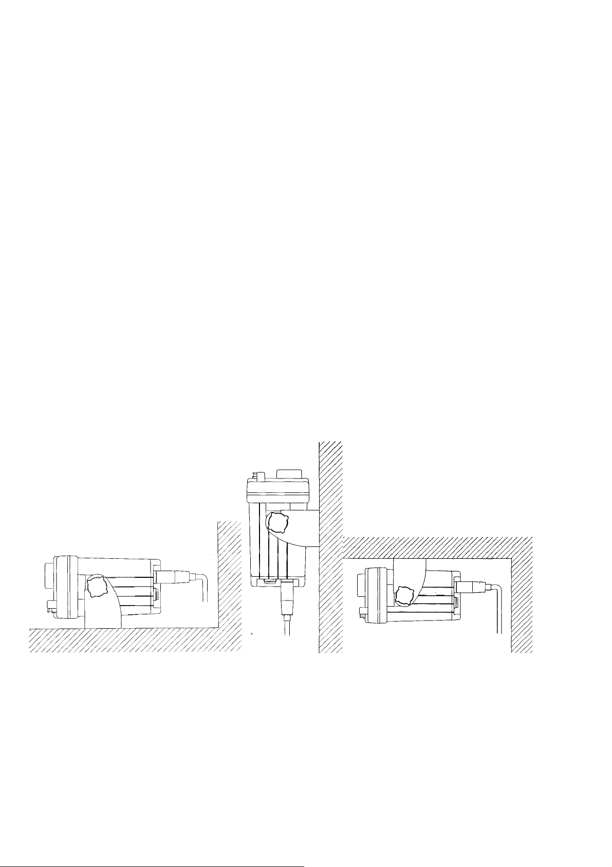
The RAY210 can be conveniently mounted on a cha rt table, bulkhead, o verhead
or any other desired location.
( Table top mount) (Bulkhead mount) (Overhead mount)
Figure 2-1 Typical Mounting Methods
6
Page 19
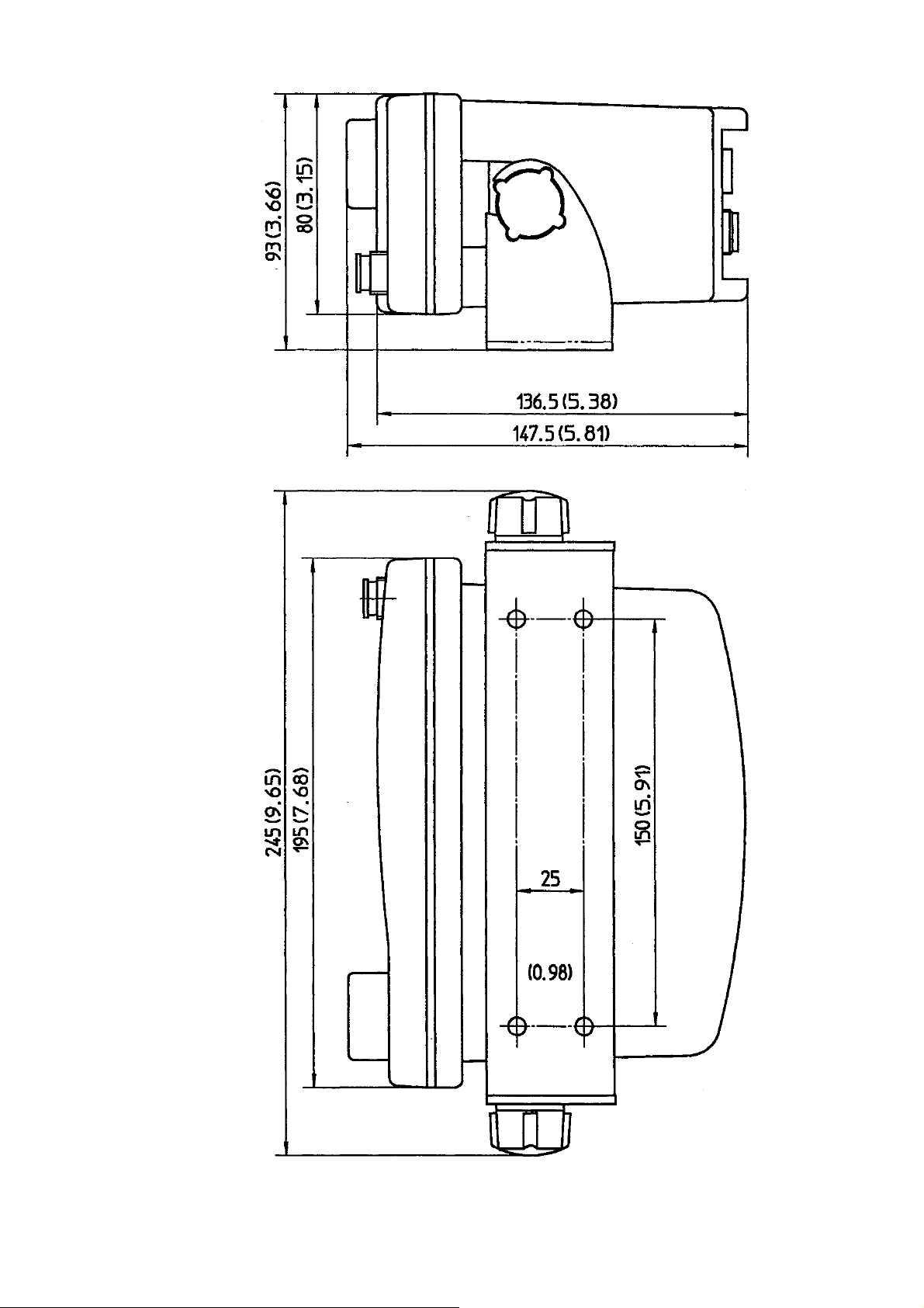
Figure 2-2 Outline and Mounting Dimens ions
7
Page 20
2.3.1 Mounting Options
The RAY210 may be given a professional appearance when mounting the radio
into a console when ordering and using the optional RAY 210 Console
Mounting Kit-Product Code M92803. The Console Mounting kit is available
from your Raymarine dealer.
2.4 ELECTRIC AL CONNECTIONS
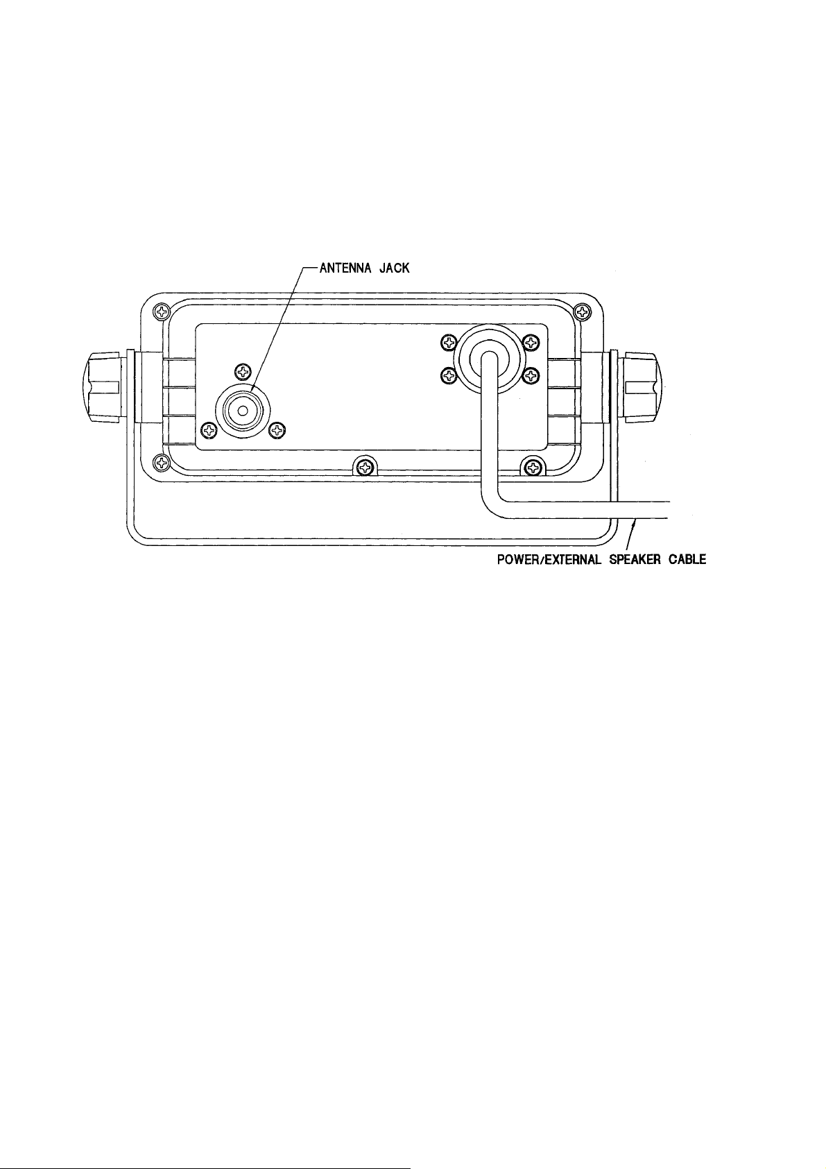
Figure 2-3 Rear View
CAUTION
DO NOT INSTALL THIS RADIO ON VESSELS WITH POSITIVE GROUND
BATTER Y SY STEMS
8
Page 21
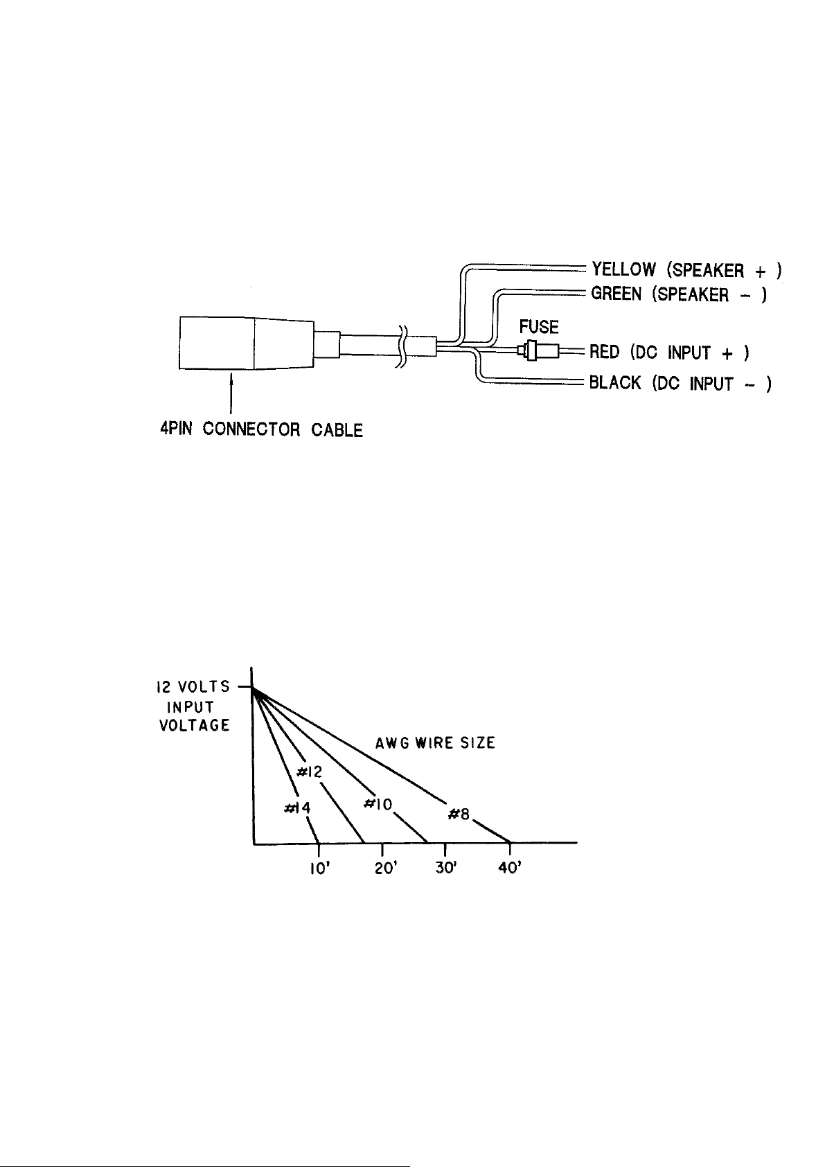
2.4.1 DC Power and External Speaker Connections
The 6 foot long power cable assembly consists of the DC power and the external
speaker cable. The DC power cable is composed of RED (+) and BLACK (-)
wires, and the external speaker cable has YELLOW (+) and GREEN (-) wires.
The RED (+ ) wire with a n in-line fuse (10 amps.) a nd the BLACK (-) w ire of
the 4 pin connector cable are used for connecting the RAY210 to the ship's 12
VDC power system. (refe r to fig 2-4)
Fig 2-4 POWER / EXTERNAL SPEAKER CABLE AND 4PIN CONNECTOR
CABLE
In most cases this length should be adequate enough to reach the DC power
source. If additional wire length is required, the cable can be extended by adding
more cable as necessary. However, for power cable runs longer than 15 feet,
larger wire diameter size should be used to prevent voltage line loss. Fig 2-5
provides recommended wire sizes to use for various cable run distance.
Fig 2-5 POWER CABLE LENGTH
Your RAY210 radio should be connected to t he nearest primary source of ship's
DC power. A typical source may be a circuit breaker on the power panel or a
fuse block near the unit. When connecting to either of these sources, the circuit
breaker or other in-line fuse should be rated at 10 amps.
9
Page 22

It is recommended that lugs be used to connect the power cable to the DC
supply and that lugs should be both crimped and soldered. This is very important
in order to insure adeq uate c urre nt draw to the eq uipme nt. Inter mittent opera tio n
may result if an insufficient connection is made to the power source. The
connection terminals should be clean, with no sign of corrosion.
The RED (+) wire is connected to the positive terminal of the power source or
battery. The BLACK (-) wire is connected to the negative (ground) of the power
source or battery. Should the power connector be inadvertently reversed, the 10
amp. in-line fuse located in the RED (+) wire will open. Check the inp ut power
leads for correct polarity with a VOM (volt /ohm meter), reconnect the leads
observing correct polarity, and replace the fuse. Use the same rate and type fuse.
2.4.2 External Speaker Connections
The YELLOW (+) wire and GREEN (-) wire are used for connecting the
RAY210 to the external speaker. (Refer to Fig 2-4)
Four watts of audio output is provided for an external 4 ohm speaker. A suitable
speaker can be purchased from your local marine dealer.
Connect the YELLOW (+) wire and GREEN (-) wire with the speaker. The
internal speaker and the external speaker will sound simultaneously.
2.4.3 Antenna C onne c tions
The coaxial cable to your VHF antenna is intended to be connected to the
antenna jack on the rear panel us ing a PL259 VHF t ype connector. The antenna
cab le may be c ut to t he re q u i re d le n gth a t inst a l la t i o n. If a longer c a b le l engt h is
required, RG-58 50-ohm coaxial cab le or equivalent cable may be used for runs
up to a maximum of 50 feet. If the distance required is even greater, then we
recommend using low loss RG-213 or equivalent cable for the entire run in
order to avoid excessive losses in power output.
If the antenna connector is likely to be exposed to the marine environment, a
protective coating of grease (similar to Dow Corning DC-4) can be applied to
the connector before connecting it to the radio. Any other extensio ns or adapters
in the cable run should also be protected by silicon grease and then wrapped
with a waterproofing tape.
2.4.4 Antenna Mounti ng S uggestions
The best radio in the world is useless without a good antenna locatio n. Mo untin g
the VHF antenna properly is very important because it will directly affect the
performance of your VHF radio. A standard VHF antenna that is designed for
use aboard boats should be used.
10
Page 23

There are several factors to consider in order to maximize the effective
communication range of the radio.
• Since VHF transmissions are essentially Line-of-Sight, mount the antenna at
the highest possible location on the vessel and free of obstruction in order to
obtain maximum range.
• Use an antenna with the highest possible gain characteristics.
• If you must extend the length of the coaxial cable between the antenna and
the radio, use a coaxial cable designed for the least amount of power loss over
the entire cable length.
• Keep the coaxial cable between the radio and antenna as short as possible.
2.4.5 Grounding
While special grounding is not generally required to VHF radiotelephone installations, it is a good marine practice to properly ground all electronic equipment
to the ship's ground system. The RAY210 can be connected to ground by attaching a wire to one of the RF connector screws on the unit's rear panel and then to
the nearest ship's ground connection point. The recommended wire to be used
for such grounding is #10 AWG.
The RAY210's cabinet was specifically designed and die-cast from aluminum to
ins u re ma x i mum no is e re j e c t io n fro m ex te r nal so ur c e s .
11
Page 24

SECTION 3
OPERATIONS
3.1 INTRODUCTION
Your RAY210 has the capability to transmit on 51 and receive on 93 Marine
VHF radiotelephone channels. There are channels that are FCC approved but
may only be used by a uthorized stations for spec ific purposes, depending o n the
type of vessel (co mmercial or non-commer cial). Take a look at Table 3-1 a nd 2
on page 22-24 which lists all of the marine VHF channels available in your
RAY210 for Inte rnat iona l and U. S. rad iotelep hone use. Full fa miliarizat io n wit h
this table is essential when selecting your channels. The international
frequencies were agreed upon by the attending countries at the 1968
International Telecommunication Union Meeting in Geneva and are in active
use around the world. The U.S. channels are those channels authorized for use in
the U.S.A. by the FCC.
3.2 CONTROLS AND LCD DISPLAY
Refer to Figure 3-1 for familia rization with the co ntrols and mode display.
3.2.1 Controls
1) On / Off and Volume Control:
This control switches the RAY210 on and off and controls the volu me level of
the internal speaker. Turning the radio On will apply power to the radio
circuitry. When the radio is on, rotating this control clockwise will increase
volume to the internal speaker and rotating this control counterclockwise will
decrease volume.
2) CHANNEL Selector Control
This control selects the desired operating channel. When the control is turned in
a clockwise direction, the channel number increases. When the control is turned
in a counterclockwise direction the channel number decreases.
3) SQUELCH Control
Provides an adjustable input signal threshold to eliminate random RF
background no ise during “no signa l” conditions. Th is control sets the s ignal-tonoise ratio at which a signal will become audible.
4) [16/9] Key
Used to select channel 16 or 9 immediately. This Key enables the following
operating mode;
12
Page 25

At the time of s hipment : n 16 9 n
Press fo r more than 3 sec : n 16 n
Press fo r more than 6 sec : n 9 n
Press fo r more than 9 sec : n 16 9 n
(n = The Previously Monitored Channe l)
This key is operative any time and will stop All Scan or Select Scan when
pressed.
5) [FUNC] (Function) Key:
When the [FUNC] key is pressed, an F will appear on the LCD to let the
operator know that a Secondary Function can be selected. To operate a
secondary function, first press the [FUNC] key, then press the desired front
panel key. To cancel a seco ndary function and return to the previous operatin g
mode, repeat the sa me procedure.
The function key enables the following operating modes and operations when
the associate d keys are depressed:
• All Scan Mode - press [FUNC] the n [SCAN] : SCAN w ill be displayed o n
the LCD.
• TX Power sett ing mode - press [ FUNC] then [1/25] :1W will be d isp laye d on
the LCD.
• DWX mode - press [FUNC] then [DWX] : DWX will be displayed on the
LCD.
• MEM mode - press [FUNC] then [MEM] : MEM will be displayed on the
LCD.
• Internationa l mode - p ress [FUNC] t hen [I NTL] : INTL w ill be d ispla yed the
LCD.
6) [SCAN] (All Scan) Key:
This key is used as a secondary function to activate the all scan mode. To
activate the a ll scan mode, press the [FUNC] ke y, then [SCAN]. SC AN will be
displayed on the LCD and the R AY210 will sequent ially scan all USA or INT L
channels (CH 01- CH 88, See Table 3-2 page 23 and 24) except weather
channels. To cancel the scan funct ion, press the [FUNC] key then [SCAN].
• If signal is present on the channel that is being scanned, the scanning will
stop until the statio n clears. After the station c lears and no signal is received fo r
five seconds, the scanning will resume. Pressing [SC] (scan continue) will
reactivate the scanning if the radio has stopped on a partic ula r cha nne l a nd the
operator wants to co ntinue.
13
Page 26

• If the radio has s topped on a channel, and the operator wants to tra nsmit on
that channel, pressing the PTT switch will cancel the scan function and the
RAY210 will rema in on that channel.
• If the radio stops on a c hannel during the scan mode due to a rece ived signal,
the operator ca n cancel the sca n function and the RAY210 w ill remain on that
channel. If no signal was present w hen the All Scan is deactivated, the radio will
revert to the channel in use prior to the selection of All Scan.
When the radio is in the All Scan mode, the keyboard is inoperative except for
the following keys : [SC], [DIM], [VOLT], and [16]. The trans mitter is inhibite d
in t he A ll Scan mode .
NOTE: During scanning operations, a VHF radio will sometimes stop on a
particular channel for no obvious reaso n. This can be caused by electr ical noise
and interference that may be commo n to a particular port or harbour area.
7) [1/25] (high / low power) key:
This secondary function is used to toggle the tra nsmit power setting between 25
watts and 1 watt. To set t he transmitter to low power sett ing (1 watt), p ress the
[FUNC] key, then [1/25]. 1W will then be displayed on the LCD and your
RAY210 will apply approximately 1 watt of power to the antenna during
transmit operation. When 1W is not displayed on the LCD, the radio is set to
provide 25 watts o f power to the ante nna. The low powe r sett ing is provided for
situations where the pa rties communicating are close to each othe r. This reduces
radio channel congestion in distant areas, allowing more individuals to use the
same channel at a given time.
Some VHF c hanne ls a re re qu ired b y the FCC to be a utomat ically s et to tra nsmi t
on low power (Refer to Table 3-2 on pages 23 and 24). The operator may
override this automatic setting on some of these channels. To override the
automatic low power setting o n authorized channels, press t he [FUNC] ke y the n
[1/25] key and hold.
8) [DWX] (Dual Watch Plus Weather) Key:
This secondary function key activates Dual Watch plus Weather Mode and
illuminates the DWX s ymbol on the LCD. I n this mode, the RAY210 will s can
(monitor) priority channel 16, a user selected channel, and selected weather
channel (monitor weather alert warnings). To operate this mode, first select a
working channel, then select a weather channel by pressing the [WX] key and
set to desired channel. Pressing [FUNC] key and then the [DWX] key will
activate the DWX mode. Pressing the [FUNC] and then the [DWX] key again
cancels the DWX mo de.
14
Page 27

• If a signal is received on either channel 16 or the selected working station
while in the DWX mode, the operator can communicate with the calling part y
and still remain in this mode.
• If a weather warning is received o n the weather station be ing monitored, the
RAY210 will e mit a ser ies of tones. The radio w ill then auto matically sw itch to
the WX mode in order to monitor the emergency broadcast.
The radio will no longer be in the DWX mode.
9) [MEM] (Memory) key:
This secondary function key stores channels into memory for select scan
functions. To store a channel using the memory, select the desired channel using
the selector k no b, press the [FUNC ] key, then [MEM]. The MEM symbol will
illuminate on the LCD and the displayed channel will be stored into memory.
The same procedure is used to remove a channel from memory. To view all
channels that are stored in memory, press t he [RCL] ke y. RAY210 will d isplay
each channel in memory, then return to t he previously selected cha nnel.
10) [INT L] (Internat ional) key:
This key causes the synthesizer to program international frequencies and
illuminates the INTL symbol on the LCD. To change to international
frequencies, press [FUNC] key, then [INTL]. To return to U.S. channel
frequencies, repeat this same procedure.
11) [WX] (Weather) key:
When pressed, puts the radio into the weather receiving mode. A WX indicator
will be displayed on the LCD along with t h e w e a ther channel number (0-9).
Rotate the channel selector knob until the desired WX channel is displayed.
Refer to Table 3-1 (page 22) for weather channe l fre quencies. Pre ssing the [W X]
key a second time returns the RAY210 to the operating channel previously used.
12) [DW] (Dual Watch) key:
Pressing this key puts the radio into the Dual Watch mode and DW is
illuminated on the LCD. The RAY210 will then monitor the current selected
channel and channel 16. If a signal breaks squelch on either channel, the radio
will change to that channel. After the channel clears, and no transmission is
received for five seconds, the radio will return to the Dua l Watch operation.
15
Page 28

13) [SC] (Scan Continue) key:
During scanning mode, if a signal breaks squelch on a certain channel, the
scanning will stop on that channel. Pressing the Scan Continue [SC] key will
resume the scan operation.
14) [SS] (Select Scan) key:
Pressing this key puts the radio into the Select Scan Mode, and MEM SCAN
will be illuminated on the LCD. In this mode the RAY210 will sc an only those
channels which ha ve been s tore d int o me mor y by t he operat or.
• If a signal breaks squelch during the scan operation, the radio will stop on
that channel a nd will resume sc anning only after a s ignal is no longer received
and the channel remains clear for five seconds.
• If a signal breaks squelch during the scan operation and you wish to communicate with the other party, when t he PTT switch is depressed, the scan mode
will deactivate and t he radio will operate normally on the channel.
If a signal is present w hen t he Select Sca n is deactivated, the radio will remain
on that channel. If no s ignal is prese nt when the Select Scan is deactivated, the
radio will reve rt to the channel in use prior to the selection of the Select Scan
Mode.
When the radio is in the Select Scan mode, the only keyboard buttons that preempt the scan are [SS] and [16]. Note that two separate sets of programmed
memory channels are possible, one set of International channels and one set of
USA channels. The tra ns mitter is inhibited in the SS mode.
15) [M1] through [M5] "quick" me mory keys:
Using these keys, the operator can store up to five c hannels in memory for quick
and convenient access any time. To store a channel in the Ml through M5 quick
memory:
• Select the desired channel with channel selector knob.
• Press and hold the desired quick memory key for approximately three
seconds until two beeps are heard.
• The memory location number will then be displayed on the LCD.
16) [RCL] (Memory Recall) key:
When this key is pressed, the R AY210 w ill display each of the channels that are
currently stored in memory for the Select Scan mode.
Upon completion, t he radio will return to the previously selected channel.
16
Page 29

17) [DIM] (Dimmer) ke y :
The [DIM] key changes backlighting level for the fro nt panel. The backlighting
is in the off condition when the RAY210 is first turned on. There are four levels
for front panel illumination (high, medium, low, and off), Pressing the [DIM]
key one time turns the back light to its brightest sett ing (high). Each s ubsequent
press of the back light key decreases the level of illumination. Once the backlight
is decreased to the “off” condition, the next press of the [DIM] key returns the
backlight to high.
18) [VOLT] (voltmeter) key :
Pressing this key will activate the unique digital voltmeter feature for fast
verification of input DC volta ge to yo ur RAY2 10.
To activate the voltmeter, press [VOLT] key. The display will then show the
input DC voltage for five s e c onds, the n w ill return to previo us operation.
19) [D/L] (s ensitivity) key :
The receiving sensitivity is changed by pres sing this key. When the RAY210 is
turned on, sensitivity is set high. To reduce receiving sensitivity, press [D/L]
key. When a t low s ensiti vit y settin g " DESENS11 is dis pla yed on the LCD .
Note: When your radio is interfered with by pagers, land mobile and TV signals,
your RAY210 can eliminate the interference by utilizing the desensitising
function.
20) Microphone PTT (Pus h-To -Ta lk) Switch :
When pressed p uts t he ra dio into t he tra nsmit mode, and a “ TX” is disp layed on
the LCD. Bar segme nts of 1 through 3 will illuminate w he n the PTT switch is
depressed at 1 Wa tt. Bar segment 4 will illu minate whe n modulatio n is detected.
At 25 Watts, se gments 1 thro ugh 6 will illu minate w hen PT T is de press ed a nd 7
wil l display when mod ulatio n is detecte d.
21) Microphone 16/9 switch :
This switch has the same function as that of the main unit.
22) Microphone Up/Down C ha nnel Switches :
These keys located on the right side of the microphone (labelled CH) allow the
operator to switch radio channel by simply pressing the appropr iate arrow. The
channel number can be increased or decreased one with each press, or if held
will continue to increase or decrease the number as long as the key is held.
17
Page 30

Figure 3-1 Layout of Controls and Connectors
18
Page 31

23) Microphone Speaker On - Off:
When [FUNC] key and [M5 ] key are pressed together for more than 10 seconds,
2 beeps sound and the microphone speaker is turned on / off. This setting
remains in me mory a fter powe r s ource is cut off.
24) Master Reset:
A master reset is performed whe n power source is turned on while [ FUNC] key
and [16/9] are pressed simultaneously. All channels will be cleared from
memory and the 16 PLUS channel will be automatically programmed back to
channel 16. Two audible beeps will follow completion of the reset.
25) Watching of power source voltage:
When the power source voltage (voltage supplied from the ship) drops below
11.0V, “dcv” is displayed o n LCD with 7 segments a nd “V”. This ind ication is
continued until power source voltage recovers to 12.0V or more, or until power
source is cut off.
26) Check on antenna condition:
Antenna conditio n (open / short) is c hecked while 25 watts TX o utput power is
transmitted. If any defect is detected, “An” is displayed on the LCD with 7
segments. This indication is continued until the defect of the antenna is
improved, or until power source is cut off.
3.2.2 LCD Display
A number of characters appear on the LCD display. The following list describes
the characters a nd when they will appear.
DESENS: will appear on the LCD display when the radio is in Desensitised
mode.
DW (Dual Watch): will appear on the LCD display when the radio is set to
monitor channel 16 or 9 and a selected channel.
DWX (Dual Watch plus Weather): will appear on the LCD display when the
radio is set to monitor channel 16 or 9, a selected channel, and a weather
channel.
INTL (International): will appear on the LCD display when International
channel frequencies are selected. When the INTL display is extinguished, U.S.
channel frequencies are selected.
19
Page 32

MEM (Memory): will appear on the LCD display to show the operator that the
displayed channel has been programmed into the Select Scan memory.
SCAN (All Scan): will appear on the LCD display when the radio is in t he Al l
Scan mo de.
WX (Weather): will appear on the LCD display when the rad io is in the Weather
mode.
TX (Transmit): will appear o n the LCD display when the microphone push-totalk switch has been pressed and the tra ns mitter circuits are providing a s ignal to
the antenna.
1W (1 Watt, Low Power Setting): will appear on the LCD display when the
transmitter output power has been set to Low Power (1 Watt), or when a low
power channel has been selected using t he channel selector knob.
F (Function): w ill appear on the LCD display when the [ FUNC] key has bee n
pressed to operate a secondary key function. The secondary ke y functions are as
follows : SCAN, 1/25, DWX, MEM, and INTL.
LCD Bar Indicator: In the transmit mode, the 7 bars indicate transmitter
conditions. During low power transmit (1W), 3 bars will be displayed
continuously and a fourth bar will indicate modulation. During high power
transmit (25 W), 6 bars will be lit continuously and seventh bar will indicate
transmit modulat ion.
V (volt) : The DC supply voltage to the RAY210 will appear on the LCD
display for 5 seconds when the [VOLT] key is press ed.
CHANNEL #: The selected channel number will appear on the LCD display
when a communication, distress, or weather channel is selected b y the operator.
Channel numbers will be displayed in two digits (01-88) for U.S A and INT L
channels as follows:
01 88
Weather channels WO to W9 are displayed in a s ingle digit (0-9) on the LCD
display as follows:
0 9
20
Page 33

3.3 OPERATING PROCEDURES
Specific operating procedures for the RAY 210 are presented on this section.
General information regarding correct marine channel usa ge may be fo und in the
Appendix section. Refer to t he Controls se ction 3.2.1 beginning on page!2 for a
thorough description of all functions.
3.3.1 Turning the power on ( Transmit/Receive)
Turn the ON/OFF/Volume control to switch the radio on. Rotate the knob
clockwise and set it at approximately the mid point of it's range.
3.3.2 Setting the volume
Rotate the Squelch co ntrol fully co unterclo ckwise, and set the ON/O FF/Volu me
control to the des ired listening level.
3.3.3 Setting the Squelch
Rotate the Squelch control clockwise until the receiver becomes "quiet" and the
audible noise coming from the internal speaker ceases.
3.3.4 Selecting a Channel
Rotate the channel selector switch to the desired channel. See Table 3-2 (Page
23 and 24) for available U.S.A. and International channels and their frequencies.
To transmit and receive on channel 16/9, press the "quick" 16/9 key. If the
[16/9] is pressed again, the RAY 210 will return to the previous channel.
NOTE: Initial communication contacts are usually made on channel 16 as all
ships and shore stations monitor this channel. Then switch to a working
frequency for genera l communicat ions.
3.3.5 Setting the Power Output
Press the [FUNC] and then the [1/25] key to select the power output. Power
setting is dependent on the distance the message is to be transmitted, and
transmitting conditions. In certain U.S. harbours and on certain channels, the
FCC requires the power to be limited to 1W. On these "req uired" cha nnels , the
RAY 210 automatically selects 1 watt operation when the channel is selected
1W will appear beside the channel number.
3.3.6 To Transmit
To transmit, press the Push-To-Talk switch on the side of the RAY 210
microphone. Speak int o the microphone using a clea r, normal voice.
The RAY 210 is designed to meet the FCC Rules Part 80.203. This rule requires
transmitter time out circuitry which will automatically disable the transmitter
after 5 minutes of continuous transmit.
21
Page 34

After 4 minutes of continuous transmit, the RAY 210 will emit two warning
tones. If t he transmitter re mains engaged for an add itional minute, or 5 minutes
total, the RAY 210 will automatically disab le the transmit operation.
At this time, the RAY 210 w ill cease transmitting, e mit an alarm, and “ot” wil l
be displayed on the LCD. To return to normal operation, the microphone FIT
switch must be d isengaged.
3.3.7 To Transmit and Receive on INTL F requencies
To transmit and rece ive on Inter natio nal freque ncies, pres s the [FUNC ] and the n
the [INTL] key, then select the desired channel. INTL will appear on the disp lay
to indicate Internat ional operation.
3.3.8 Selecting a Weather Channel
To select and rece ive a weather channel, press the [WX] key and then rotate the
channel selector switc h to the desired channel (0-9). Refer to the be low Table 31 for specific weather channel frequencies. When in the weather mode, the
transmitter is disabled.
Channel Freque ncy (MHz) Type Traffic Function-Ship to Shore
WX0 163.275 NOAA Weather Receive O nly
WX1 162.550 NOAA Weather Receive O nly
WX2 162.400 NOAA Weather Receive O nly
WX3 162.475 NOAA Weather Receive O nly
WX4 162.425 NOAA Weather Receive O nly
WX5 162.450 NOAA Weather Receive O nly
WX6 162.500 NOAA Weather Receive O nly
WX7 162.525 NOAA Weather Receive O nly
WX8 161.650 Canad ian Weath. Receive Only
WX9 161.775 Canad ian Weath. Receive Only
Table 3-1 RAY 210 VHF WEATHER CHANNELS AND FREQUENCIES
22
Page 35

RAY 210 VHF RADIOTELEPHONE CHANNELS
S
Channel
Design.
01 156.050 156.050 160.650 VTS/Portops Yes Yes
02 #
03 #
04+ 156.200 156.200 160.800 Can. SAR/Po rt Ops No Yes
05 156.250 156.250 160.850 Port Operations No Yes
06 156.300 156.300 156.300 Safety; Ship/Ship Yes No
07 156.350 156.350 160.950 Com'l Yes Yes
08 156.400 156.400 156.400 Com'l Yes No
09 156.450 156.450 156.450 Call & Ship/ Ship Yes Yes
10 156.500 156.500 156.500 Co m' l & Sh ip/ S hip Yes Yes
11 156.550 156.550 156.550 Co m' l & Sh ip/ S hip Yes Yes
12 156.600 156.600 156.600 Port Operations Yes Yes
13** 156.650 156.650 156.650 Nav. Bridge/Br idge Yes Yes
14 156.700 156.700 156.700 Port Operations Yes Yes
15# — 156.750 156.750 Environmental - 16 156.800 156.800 156.800 Emerg/Calling Yes Yes
17* 156.850 156.850 156.850 State C ontr olled Yes Yes
18 156.900 156.900 161.500 Com'l Yes Yes
19 156.950 156.950 161.550 Com'l Yes Yes
20 157.000 157.000 161.600 Port Operations Yes Yes
21 (CG) 157.050 157.050 161.650 Coast Guard Yes Yes
22 (CG) 157.100 157.100 161.700 Coast Guard Yes Yes
23 (CG) 157.150 157.150 161.750 Coast Guard Yes Yes
24 157.200 161.800 161.800 Public Corresp. No Yes
25 157.250 161.850 161.850 Public Corresp. No Yes
26 157.300 161.900 161.900 Public Corresp. No Yes
27 157.350 161.950 161.950 Public Corresp. No Yes
28 157.400 162.000 162.000 Public Corresp. No Yes
Frequency (MHz) FUNCTION
TX RX
(U.S.A.)
156.100 160.700 Port Operations Yes Yes
156.150 160.750 Port Operations Yes Yes
RX
(INTL)
TYPE OF
TRAFFIC
SHIP TO
SHIP
HIP TO
SHORE
Table 3-2
*1 Watt only
**1 Watt initially. May override to full transmit power via front panel
operations.
+ Assigned by Canadian Government, proper authorization must be ensured
prior to use.
# The transmitter is automatically disabled when channels 2 and 3 for USA
channels and channel 15 for USA and International channels is selected.
23
Page 36

Frequency (MHz) FUNCTION Channel
S
Design.
60+ 156.025 156.025 160.625 „ _ _
61+ 156.075 156.075 160.675 - - 62+ 156.125 156.125 160.725 - - 63 156.175 156.175 160.775 ~ - 64+- 156.225 156.225 160.825 - - 65 156.275 156.275 160.875 Port Operations No Yes
66 156.325 156.325 160.925 Port Operations Yes Yes
67** 156.375 156.375 156.375 Com'l Yes No
68 156.425 156.425 156.425 Non Com'l Yes Yes
69 156.475 156.475 156.475 Non Com'l Yes Yes
70# - 156.525 156.525 DSC DSC Code only
71 156.575 156.575 156.575 Non Com'l Yes Yes
72 156.625 156.625 156.625 Non Com'l Yes No
73 156.675 156.675 156.675 Port Operations Yes Yes
74 156.725 156.725 156.725 Port Operations Yes Yes
75# - 156.775 156.775 - - 76# - 156.825 156.825 ' - 77* 156.875 156.875 156.875 Port Operat ions Yes No
78 156.925 156.925 161.525 Non Com'l Yes Yes
79 156.975 156.975 161.575 Non Com'l Yes Yes
80 157.025 157.025 161.625 Non Com'l Yes Yes
81 157.075 157.075 161.675 Coast Guard Yes Yes
82 157.125 157.125 161.725 Coast Guard Yes Yes
83 157.175 157.175 161.775 Coast Guard Yes Yes
84 157.225 161.825 161.825 Public Corresp. No Yes
85 157.275 161.875 161.875 Public Corresp. No Yes
86 157.325 161.925 161.925 Public Corresp. No Yes
87 157.375 161.975 161.975 Public Corresp. No Yes
88 157.425 157.425 162.025 Com'l Yes No
TX RX
(U.S.A.)
RX
(INT'L)
TYPE OF
TRAFFIC
HIP TO
SHIP
SHIP TO
SHORE
Table 3-2 (Continued)
*1 Watt only
**1 Watt initially. May override to full trans mit power via front pane l ope rations
+ Assigned by Canadian Government, proper authorization must be ensured
prior to use.
# The transmitte r is disabled whe n channels 75 and 76 a re selected. C hannel 70
is now used for DSC calling only, therefore transmission is disabled on c hannel
70 in this radio.
24
Page 37

SECTION 4
TECHNICAL
4.1 RECEIVING CIRCUIT OPERATION:
4.1.1 Antenna Switching Circ uit:
A signal received at the antenna connector J1 goes to the antenna switching
circuit composed of pin diode Dl and D2 via the low pass filter.
4.1.2 High Frequency Amplifier Circuit:
After being a mplified by transistors RF AMP1 (Q21) and RF AMP2 (Q22),the
high frequency signal which is sent from the antenna switching circuit goes
through BPF to suppress t he undesired signals . Then the high frequency signal
is added to the 1st mixer of the next step diode (D15, D16).
A local oscillating signal from PLL unit (134MHz range) is input to this 1st
mixer, mixed with the receiving signal to make the 1st intermediate frequency
(21.6MHz).
4.1.3 1st Intermed iate Frequency Amplifier Circuit
After undesired signals have been removed by a pair of crystal filters (FIL101),
the 1st intermediate freq ue ncy signal generated in the 1st mixe r is a mplified at
the 1st IF AMP (Q30).
4.1.4 2nd Intermediate Frequency Circ uit:
The 1st intermediate frequency signal is added to IC307, which is composed of a
local oscillating circuit, a mixer circuit, a limiter amplifier circuit, a
re modu lation circuit and a squelch cir cuit.
The 1st intermediate fre quency signal is converted to 455 KHz 2 nd inte rmediate
frequency signa l after being mixed with 21. 145M Hz signal which is output from
the local oscillating circuit in IC307 and a crystal oscillator ( XT A L4 ). Undesired
signals are removed fro m t his signa l by a c era mic filter (FI L3), a nd t he s ignal is
subjected to amplific a tion in the limiter amplifier circuit.
The amplified 2nd intermediate frequency signal is re-modulated by the remodulation circuit composed of a circuit in the IC307 and a ceramic
discriminate element (FIL4).
Then it is outp ut as a low frequency signal.
25
Page 38

4.1.5 Low Frequency Circuit:
The low frequency signal re-modulated by IC307 obtains -6dB/oct characteristic
by going through the de-emphasis circuit which contains BUFF (IC13A) and
LPF (Q25). Then the signal is input to the low frequency section of CPU AF
board.
4.1.6 Squelch Circuit:
If no signal is input to the a ntenna, noise s ignal is a mplified b y the amplif ier ( IC
13B), As the result of receiving t he amplifi ed noise signal, the sq uelch circuit o f
IC307 outputs BUSY signal. Sq uelch le vel is co ntrolled b y VR101.
4.1.7 Low Frequency Treatment Circuit (CPU AF Board):
The re-modulated low frequency signal is amplified in AMP (Q7). Its volume
can be adjusted by t he tone volume (VR 102).
BUSY signal, output from the squelch circuit (6), becomes a MUTE signal after
being conditioned in CPU c ircuit. T he low freque ncy signa l is turned o n a nd of f
by the transistor switch (Q6) which is driven by this MUT E signa l.
The low frequency signal further undergoes power-amplification in the lowfrequency-power-amplifier (IC 305) to drive the speaker. With the amplifier
circuit (IC6, Q8, Q10), which drives the microphone speaker, it is possible to
monitor the receiving tone heard from the microphone speaker. This driving
circuit can be turned on and off by key operation.
4.1.8 WX Alert Detection:
The tone selector (IC10 RF Board) detects the 1050Hz alert tone if it is
contained in the re-modulated receiving s ignal. The operating mode is changed
to WX receiving mode when CPU confirms that the alert tone has been detected.
4.2 TRANSMITTING CIRCUIT OPERATION
4.2.1 Microphone Amplifier Circuit:
Voice signal from the microphone is amplified by TX MIC AMP (IC5AJC5B)
in the CPU AF Board. At the same time, the voice signal obtains pre-emp hasis
characteristic of 6 dB/oct in the range from 300Hz to 3KHz. The oscillation
width of this signal is limited by LIMITER circuit (D5) of the RF board. The
harmonic wave distortion generated by this oscillation width limitation is
removed by TX MOD LPF (IC31). Then the voice signal is input to VCO
se ctio n o f P L L c irc u it as a mod ula t io n s ig na l. Th is mo du la t ion s i gna l fre q ue nc y
is modulated directly by the variable capacity dio de D11 o f VCO.
26
Page 39

4.2.2 High Frequency Power Amplifier Circuit:
When the mode turns to be in a state of t ransmitting by turning the PTT switch
of the micr ophone, frequency of PLL is set up t o the tra nsmitting freq uency .T he
range of oscillatio n frequency of VCO is shifted by this transmitting/receiving
shift circuit (Q31). This high frequency signal of VCO undergoes the
amplificatio n in the buffer amplifie r Q17 and driving amplifie rs Q4, Q3. After
being power-amplified to a maximum output power of 25W by the power
module (IC1), it is tra nsmitted as a transmitt ing output power from the ante nna
connector J1) via the ante nna switching circuit
4.2.3 APC Circuit:
The output power is detected as a direct current signal by APC detecting circuit
(D3). APC control circ uit composed of Q1, Q2 and IC2 controls the transmittin g
output power, together with 25W/1W switching circuit (Q5).
4.2.4 Antenna M o nit ori ng C ir cuit:
After passing through LPE which depresses harmonic waves, the amplified
transmitting output power is outputted as an antenna output power via a split
line on the PC board pattern and an antenna monitoring circuit composed of
D311 and D312. After being detected at D311 and D312, the direct current
signals are amplified at SWR REF AMP (IC30B) and SWR FWD AMP
(IC30A) respectively. Then they are converted to digital signals by the A/D
converter in CPU. The an tenna monito ring circuit a lways watc hes the co nditio n
of the antenna by observing these digital signals.
If the antenna is normal: VSWR - R < VSWR - F
If the antenna is open or short: VSWR - R ≥ VSWR - F
4.3. PLL CIRCUIT OPERATION
The oscillation circuit of PLL IC (IC9) oscillates 12.8MHz frequency by the
crystal oscillator (XTAL1) attached to it. This 12.8MHz frequency is divided
into 1/512 by the divider inside the IC to make 25KHz frequency, which is the
reference frequency of PLL. Frequencies are set up at the time of transmitting
and receivin g res pect ive ly by data fro m CPU (D ATA, C LK, ST B). Erro r signa ls
from PLL pass t hrough the loop filter (LP F). Frequencies o f these error signals
are controlled by variable capacity diode (DIG) of VCO (Q15).
27
Page 40

Fig.4-1 Block Diagra m / RF PCB
28
Page 41

Fig.4-2 Block Diagra m / CPU PCB
29
Page 42

SECTION 5
MAINTENANCE
5.1 GENERAL
The purpose of this section is to provide servicing instructions to the service
technician. The RAY 210 is designed to provide long periods of trouble-free
operation. It is recognized, however, that environmental and other factors may
result in a need for occasional service.
5.1.1 How to contact Raymarine Technical S upp ort
The Americas: +1 800 539-5539 ext.2444 or +1 603 881-5200 ext.2444
UK, Rest of the World: +44 23 6971 4713
Our Technical S upport Specialists are available to answe r installation, operation ,
and trouble-shooting questions about your Raymarine unit Our Technical
Support Department may also be reached via the Internet, where a
comprehensive lib rary of frequently asked questions and solut io ns is available.
http://www.raymarine.com/support
Accessories and Parts
The Americas: 1-800-539-5539 ext.2333 or (603) 647-7530 ext.2333
UK, Rest of the World: +44 23 9269 3611 ext. 2029,
service.admin@raymarine.com
Many Raymarine accessory items and parts are available through your
authorized Raymarine dealer. However, if you are in need of an item not
available through your retailer feel free to contact our Customer Service
department. If you are uncertain about what item to choose for your Raymar ine
unit please contact our Technical Support Department prior to placing your
order.
Product Repair and Service: +1 800 539 5539 ext. 2118
In the unlikely event your Raymarine unit should develop a problem please
contact the Raymarine dealer from where the unit was purchased. Your
Raymarine dealer is best equipped to handle your service needs. Service may
also be obtained by returning your unit to Raymarine's Product Repair Centres a t
the addresses below:
The Americas:
Service Department,
Raymarine Inc.,
22 Cotton Road, Unit H
Nashua
NH 03063-4219
UK, Rest of the World:
Service Department,
Raymarine Ltd.,
Anchorage Park
Portsmouth, Hampshire
PO3 5TD
30
Page 43

We will do everything possible to return your unit as quickly as possible. To
inquire about the status o f your unit our Pr oduct Repair Centre may be reached
by calling 1-800-539 5539 ext.2118.
Please keep a record of the serial number of your unit and have this number
rea dy when you call.
5.2 PREVENTATIVE MAINTENANCE
The procedures listed below for the RAY 210 should be performed at monthly
intervals to minimiz e the possibility of an equipment failure and assure optimum
performance.
1. Inspect the antenna syste m. Pa y part ic ula r attention to the cleanliness of the
antenna connectors and the condition of any soldered connect io ns.
2. Fuse holders and their connections may be subject to corrosion which can
increase circuit resistance. The in-line fuse should be removed from its holder,
inspected and cleaned of any accumulation of dirt or cor rosion.
3. The radio front panel should be cleaned w ith a tissue or a so ft non-ab rasive
cloth. Care should be exercised when cleaning any plastic surface to prevent
scratching, especially the LCD window a rea. Mild soap and water may be used
in stubborn cases. The radio case should be cleaned of any salt spray or dust as
often as necessary.
CAUTION Do not use solvents or other chemicals for cleaning this equipment.
NOTE: The following a lignment procedures have been pro vided in this manua l
to aid FCC licensed technicians and service personnel only.
5.3 ALIGNMENTS AND SERVICE
The RAY 210 is co mpletely aligned at the factory and normally does not req uir e
any readjustment at installation. However, it is considered good a practice to
verify the power o utp ut, modulation, and receiver performance on occasion.
The test equipment listed in paragraph 5.3.1 is used for the test setup shown in
Figure 5-1. This test setup may be used either in part or completely to perfor m
the following adjustments should any align men ts be re quire d.
31
Page 44

Figure 5-1 Test Setup
5.3.1 Test Equipment
1. DC Power Supply (20V.10A) set at 13.6Vdc
2. RF Power Meter (40W.50 ohm, 150-200MHz)
3. RF signal Generator (50 o hm Output, 150-200MHz)
4. FM Linear Detector (FMLD) or Deviation Monitor 150-200 MHz
5. Fr equency Co unte r
6. D igit al Voltmet er
7. Oscilloscope (any oscillos c ope accurate for audio signal tracing)
8. SIN AD M e te r
9. Distortion Meter
10. Toggle Switch (fo r use as a PTT switch)
11. Coaxial Switch for TX/RX An tenna s witching
5.3.2 PLL Adjustment (TRANSMITTER/RECEIVER)
1. Connect the power supply (13.6V, 10A) to the power line and the PTT
switch to the microphone terminal.
2. Connect digital voltmeter or high impedance tester (positive lead to TP2,
negative to ground) and adjust CV2, CV3 on the RF module as shown in
Table 5-1.
Sequence Item Condition Adj. point
1 TX transmit CH1 6 CVS 3.5±0.1Vdc
2 RX receive CH1 6 CV2 2.5±0.1Vdc
3 RX receive CH WXO ----- check for 5.5 ±0.3Vdc
Adj. volt.
Table 5-1
32
Page 45

5.3.3 Frequency Adjustment (TRANSMITTER)
1) Connect the coupler output to a frequency counter, set the radio on CH16
(156.800MHz), key to transmit, and read the indication on the frequency
counter.
2) Adjust trimmer capacitor CV1 on the RF module for the desired frequency
(156.800MHz) ±200Hz on the frequency counter.
5.3.4 Modulation Adjustment (TRANSMITTER)
1) Connect the coupler output to an FM linear detec tor.
Connect an audio oscillator to the microphone connector and key to transmit.
2) Set the audio oscillator output to –20d Bm, 300Hz and adjust RV5 on the RF
module for a deviation on 4.5 kHz ±300Hz.
3) Set the audio oscillator o utput to –43d Bm, 1kHz a nd read the deviatio n meter
(±2.8 kHz ~ ±3. 2 k Hz).
5.3.5 Power Output Adjustment
1) Connect an RF power meter to the antenna connector through the coupler.
Key to transmit a nd adjus t RV1 a nd RV2 o n the R F Board as shown in Tab le 5-
2.
Sequence
1 13.6VDC H/L:L RV1
2 13.6VDC H/L:H RV2
Condition Adj. Point Target Power
0.9W ±0.05W
Low Power
High Power
(limit 1.0W)
24W ±0.5W
(limit 25W)
Table 5-2
5.3.6 RF Sensitivity Adjustment (RECEIVER)
1) Connect an RF signal generator to the antenna connector and a S INAD meter
to the external speaker line.
2) Set the deviation of the RF signal generator to lkHz+/-3Hz.
3) Set the output level of the RF signal generator and adjust T1 ~ T7, T9 and
T10 on the RF module, as shown in Table 5-3.
Sequence
1 CH.88(157.425 MHz) SG. output:
60dB µ
2 CH.WXO SG. output: –6dB µ T2 ~ T7
Condition Adj. Point Target Level
T2 ~ T7
T9,T10
T9,T10
Max. Sensitivity
Over 12dB SINAD
Table 5-3
33
Page 46

5.3.7 Weather Alert Frequency Adjustment (RECEIVER)
1) Connect an RF signal ge nerato r to the antenna connector. Set the RF signa l
generator as follows:
Frequency: 162.550MHz with no modulation
Output level: 60dB µ
2) Select the weather channel WX1.
3) Connect a frequency counter to TP1 on the RF Board and adjust RV6 to
obtain 1050kHz +/-5Hz on the frequency counter.
5.4 TROUBLE SHOOTING GUIDE
Table 5-4 provides a general trouble-shooting chart for use by a technician to
isolate circuitry failures to specific functional areas within the RAY 210.
5.4.1 Master Reset
The first step in attempting to clear a problem associated with the general
operation of this radio is to perform a MAST ER RESET. This can be done by
pressing the [FUNC] and [16] keys s imult aneo us ly, and while holding, turning
the power on. This should be performed anytime a component or PCB within the
radio is replaced. This function will clear the RAY210 memory and will return it
to its factory settings.
It should be noted that micro-components within the radio are generally not field
replaceable, there fore, repairs to the radio typically go down to t he board leve l
only. A replacement parts list for the RAY210 can be found in Section 6.
Table 5-4 TROUBLESHOOTING CHART
Item
Number
1 Unit does not turn on a. Defective power switch
2 No sound with AF signal
applied to pin 1 of IC305
3 No sound with AF signal
applied to volume
control
Symptom Possib le Cause
b. 10 amp. fuse in power line open
c. Diode D24 open
d. Noise filter L309 open
e. Capacitor C358 and C369 shorted
f. Defective regulator IC15 (5V)
a. Defective internal speaker
b. Defective IC305 and/or associated
components
a. Defective volume control
b. Defective mute circuitry (Q6 IC1)
[CPU AF Board]
34
Page 47

Table 5-4 (Continued)
Item
Number
4 Squelch circuit inoperative a. Check squelch contro l
5 No receive (RX) a. Defective regulators 1C 15(5V) and 1C
6 Low receiver frequency a. Check antenna and connector for
Symptom Possible cause
b. Defective IC307 and/or associated
circuitry between pins 7 and 9
17 (8V)
b. Defective Q33 (KXB+)
c. Check IC 307 audio output voltage at
pin9
d. Defective AF amplifier IC 305
e. Defective mute circuitry (Q6 IC1)
[CPU AF Board]
f. Check XTAL4 output for 21.145MHz
signal
g. Check 21.6MHz output of first mixer
Q23, D15, DIG
h. Check 21.6MHz outp ut of ceramic
filter FIL101
i. Check 21.6MHz output of first IF
amplifier Q30
j. Check 455 kHz signal from ceramic
filter FIL3
k. Failure of VCO circuit (Q13, Q15, Q17
and/or PLL IC9)
l. Defective CPU (IC1) [CPU AF Board]
possible corrosion or bad connection
b. Failure of the output from Q21, Q22,
Q30 and/or IC307
c. Check the output level of VCO per
para.5.3.1
7 CPU inoperative [CPU AF
Board]
8 D is p lay ma l fu n c t i o n
[CPU AF Board]
a. Turn off the power once, and try again
b. Check CPU clock frequencies (pins 36
and 37 of IC1)
c. If clock freq uency is not present, check
for +5VDCline(IC4)
a. Check the interconnection to the LCD
display
b. Inoperative CPU
35
Page 48

Table 54 (Continued)
b
e
f
g
i
n
a
g
o
a
o
b
Item
Number
9 No transmit(TX) a. Defective PTT switch
10 Low RF power output a. Check RF power output from IC1. If
11 Poor or no mo dulat ion
12 PLL output frequency or
incorrect
Symptom Possible cause
. Defective regulators IC15 (5V), IC17
(8V)
c. Defective Q32 (TX + B)
d. Check power transmit circuit (Q3, Q4,
IC1)
. Failure of VCO circuit (Q15 and/or
Q17) or PLL (IC9)
. Check PLL control voltage for 3.5
VDC at TP1 or channel 16
. Failure of talk detection circuit (Q9)
[CPU AF Board]
t checks good, check the triple P type
etwork component (L1, L2, C3, etc.)
nd antenna switching diode ( D2). If not
ood then check the voltage level
utputs of the drive amplifiers Q3 and
Q4 as well the associated circuitry
b. Check power control circuit (Q1, Q2,
Q5) and IC2
. C heck VCO o utp ut fre que ncy a t pi n8
f PLL10. PLL phase detector outp ut at
pin 5 of PLL IC9a associated circuitry
b. Check 12.8MHz crystal (XTAL1)
a. Check frequency of 12.8MHz crystal
(XTAL1)
. Check the frequency input at pin 8 or
IC9 and verify the transmit frequency
36
Page 49

SECTION 6
6.1 PARTS LIST
******PF PCB Assembly Section******
DESCRIPTION Q'ty Symbol Parts No.
Capacitor
Ceramic, 15pF (2125) 2 C7,361
Ceramic, 33pF (2125) 2 C4,5
Ceramic, 1000pF (3216) 4 C6,12,18,20
Ceramic, 1000pF 61 C9,21,22,23,24,25,26,27,30,31,32,33,35,36,40,8
Ceramic, 0.5pF 3 C137,402,404
Ceramic, 1pF 1 C109
Ceramic, 2pF 3 C13,108,117
Ceramic, 5pF 4 C123,129,132,139
Ceramic, 6pF 1 C136
Ceramic, 7pF (UJ) 1 C113
Ceramic, 8pF 3 C130,138,145
Ceramic, 10pF 1 C110
Ceramic, 15pF 2 C10.34
Ceramic, 10pF (UJ) 1 C114
Ceramic, 18pF 1 C142
Ceramic, 33pF 4 C28,95,144,146
Ceramic, 27pF 1 C29
Ceramic, 39pF 1 C156
Ceramic, 47pF 1 C37
Ceramic, 51pF 1 C94
Ceramic, 56pF 1 C157
Ceramic, 68pF 1 C104
Ceramic, 91pF 1 C153
Ceramic, 220pF 3 C38,159,160
Ceramic, 6800pF 2 C39.102
Ceramic, 2200pF 2 C41.103
Ceramic, 0.1µF 18 C96,150,152,155,158,161,225,228,232,234,334,
Ceramic, 0.01µF 6 C167,168,148,172,407,406
Ceramic, 0.022uF 2 C164.101
Tant., 0.1µF /25V 4 C15,99,226,349
Tant., 1µ F/16V 7 C42,98,162,169,227,229,332
Tant., 2.2µF/10V 2 C100.223
Tant., 4.7µF/10V 2 C163,222
Tant., 10µF / 16V 8 C45,154,166,224,231,236,116,385
Elec., 4.7µF/25V 1 C335
Elec., 22µF / 16V 1 C44
Elec., 47µF / 16V 1 C337
0,97,106,107,111,115,118,119,502,121,122,124,
126,127,131,133,134,140,141,143,147,149,151,
170,245,246,250,105,362,363,368,377,378,379,
501,381,383,11,14,16,359,360,336,401,403
364,365,369,382,343,344,384
37
Page 50

DESCRIPTION Q'ty Symbol Parts No.
Elec.,47uF/25V 2 C17.19
Elec., 100µF / 25V 4 C358,338,340,346
Elec., 1000µF / 25V 2 C333,370
Diode
Diode M1402 1 Dl
Diode M1308 1 D2
Diode 1SS345 3 D3,311,312
Diode 1SS226 2 D9,25
Diode 1SS184 1 D303
Diode 1SS239 2 D15,16
Diode 1SV166 1 D10
Diode 1SV214 1 D11
Diode 1SV128 2 D12,14
Diode DAP202K 2 D5.317
Diode DAN202K 4 04,19,304,316
Diode DA204K 1 D310
Diode FMB-G24H 1 D24
Transistor
Transistor 2SB1185 1 Q1
Transistor 2SC4116 2 Q2,16
Transistor 2SC3357 1 Q3
Transistor 2SC4226 6 Q4,13,17,21,22,23
Transistor 2SA1298 2 Qll,33
Transistor 2SC1623 1 Q25
Transistor 2SC3123 1 Q30
Transistor 2SB798 1 Q32
Transistor 2SK508 1 Q15
Transistor DTC114EKA 5 Q5,12,20,31,34
Transistor DTA143EKA
Resistor
Resistor 1 ohm 1/4W 1 R463
Resistor 10k ohm 1/4W 1 R1
Resistor 150 ohm 1/4W 1 R2
Resistor 10 ohm 3 R6,15,19
Resistor 22 ohm 3 R67,114,351
Resistor 33 ohm 4 R7,18,20,107
Resistor 47 ohm 2 R182.203
Resistor 51 ohm 2 R436.442
Resistor 68 ohm 1 R104
Resistor 100 ohm 10 R16,55,64,105,109,lll,115,117,118,99
Resistor 330 ohm 2 R5,62
Resistor 470 ohm 5 R14,23,119,349,430
Resistor 680 ohm 4 R68,98,202,480
Resistor 820 ohm 1 R128
Resistor 1k ohm 9 R9,13,17,60,63,183,434,350,473
Resistor 1.2k ohm 1 R51
Resistor 1.5k ohm 3 R127,440,451
Resistor 2.2k ohm 6 R32,58,110,125,138,472
Resistor 3.3k ohm 4 R3,8,123,431
1 Q6
38
Page 51

DESCRIPTION Q'ty Symbol Parts No.
Resistor 4.7k ohm 7 R22,52,180,453,454,464,471
Resistor 5.6k ohm 2 R30,113
Resistor 6.8k ohm 1 R129
Resistor 8.2k ohm 3 R103,134,179
Resistor 10k ohm 21 R4,11,12,21,31,46,47,48,53,61,112,108,1
24,133,181,437,438,439,441,456,467
Resistor 22k ohm 1 R54
Resistor 33k ohm 7 R100,106,131,136,432,433,121
Resistor 39k ohm 2 R24,25
Resistor 47k ohm 5 R49,50,56,130,201
Resistor 56k ohm 4 R26,27,28,29
Resistor 68k ohm 1 R204
Resistor 100k ohm 2 R59,120
Resistor 150k ohm 5 R122,132,468,126,137
Resistor 220k ohm 2 R10.102
Coils & Tr ans fo r me r
Coil, 3T 2 L6,7
Coil, 5T 4 Ll,2,3,5
Coil, 1ST 2 L38,39
Coil, LK2125R12K 1 L8
Coil, LK21251ROK 1 L19
Coil, LK21252R2K 1 L17
Coil, LK21254R7K 2 L312.313
Coil, LK21256R8K 1 L16
Coil, LK2125100R 1 L18
Coil, LK2125100K 3 L13,14,15
Line Filter ELKF101FA 3 L302,314,315
Line Filter N3002 1 L309
Inductor, LAL04SK6R8K 1 L4
RF Transformer SMD0100 1 T1
RF Transformer SMD0101 6 T2,3,4,5,6,7
RF Transformer SMD0102 2 T9,10
RF Transformer LTR0016 1 T8
IC
IC M57710A(S-AV6) 1 IC1 1032698-85
IC LM2904 2 IC2,31
IC MB1505PF 1 IC9
IC BA1604F 1 IC10
IC NJM3404AM 2 IC13,30
IC 78M05 1 IC15
ICTA7280P 1 IC305 G623760-15
ICTA31136FN 1 IC307
ICTC4S66F 1 IC308
Miscellaneous
Filter 21.6RB 1 FIL101
Filter CFWM455E 1 FIL3 G263479-18
Filter CDB455C24 1 FIL4
Crystal 12.8MHz 1 XTL1
Crystal 21.145MHz 1 XTL4 G263479-19
Variable Capacitor 20p 1 CV1
Variable Capacitor 10p 2 CV2,3
39
Page 52

DESCRIPTION Q'ty Symbol Parts No.
Variable resistor 10k ohm 4 RV2,3,4,5
Variable resistor 3k ohm 2 RV1,6
Connector 52559-3177 1 J101
Connec tor IL-S-6 P-S2TS-EF 1 J104
Connector IL -S4P -S2TS-EF 1 J103
Connec tor IL-S-2 P-S2TS-EF 1 J107
Connector B2P - VH 1 J106
RF Connecto r 1 J105
40
Page 53

******CPU PCB Asse mbly******
DESCRIPTION Q'ty Symbol Parts No.
Capacitor
Ceramic, 33pF 2 C18.19
Ceramic, 100pF 1 C23
Ceramic, 220pF 3 C6,7,8
Ceramic, 1000pF 20 C20,27,28,44,47,48,49,50,51,52,53,54,55,56,57,5
Ceramic, 4700pF 1 C31
Ceramic, 6800pF 1 C22
Ceramic, 0.047uF 2 C21,29
Ceramic, 0.082uF 1 C100
Ceramic, 0.01µF 2 C4,5
Ceramic, 0.1µF 7 C1,2,3,10,24,26,45
Tant., 0.47µF 25V 2 C25,40
Tant., 1µ F 16V 3 C41.42.43
Tant., 1µ F 50V 1 C17
Tant., 10µF 16V 10 C14,15,32,33,34,36,37,38,39,64
Elec., 100µF 16V 1 C46
Elec., 220µF 25V 1 C16
Diode
Diode UDZ9.1 1 Dl
Diode DA204K 1 D2
Transistor
Transistor 2SA1298 1 Q9
Transistor 2SC1623 2 Q3,7
Transistor 2SD1767 4 Q4,5,10,11
Transistor DTC114EKA 3 Q1,2,8
Transistor DTC343TK 1 Q6
Resistor
Resistor 10 ohm (3226) 1 R64
Resistor 22 ohm (3226) 1 R14
Resistor 120 ohm (3226) 6 R87,88,89,94,98,99
Resistor 330 ohm (3226) 1 R15
Resistor 0 ohm 1 R44
Resistor 10 ohm 1 R46
Resistor 100 ohm 2 R37.47
Resistor 220 ohm 1 R100
Resistor 330 ohm 1 R42
Resistor 1k ohm 24 R6,7,9,10,11,63,66,67,72,73,74,75,76,77,78,79,8
Resistor 1.2k ohm 2 R16,31
Resistor 2.2k ohm 4 R24,12,13,95
Resistor 3.3k ohm 2 R26,45
Resistor 4.7k ohm 7 R69,70,71,92,96,175,93
Resistor 5.6k ohm 2 R36,38
Resistor 6.8k ohm 1 R28
Resistor 10k ohm 8 R19,30,35,43,49,50,65,90
Resistor 18k ohm 1 R17
Resistor 22k ohm 3 R22,40,41
Resistor 33k ohm 2 R4,5
8,59,60,61,62
0,81,82,83,84,85,86,33
41
Page 54

DESCRIPTION Q'ty Symbol Parts No.
Resistor 39k ohm 1 R23
Resistor 68k ohm 1 R29
Resistor 100k ohm 5 R21,25,39,62,97
Resistor 150k ohm 1 R27
Resistor 470k ohm 1 R32
IC
IC M3825728GP 1 IC1
IC BR93LC56 AF 1 IC2
IC M51951AML 1 IC3
ICTA78L05F 1 IC4
IC LM2092NS 1 IC5
IC NJM386M 1 IC6
Miscellaneous
Switch SKQ MAL 15 S1,2,3,4,5,6,7,8,9,10,11,12,13,14,15
Filter ELKF101 FA 1
Crystal 4.91MHz 1 X1
ELFC004-BG 1 EL1
LampT-3/4 6 PL1,2,3,4,5,6
Transformer T-7-073 1 L1
LCD TD 624002 1 U1
Connector 52559-3317 1 J1
Connec tor IL-S-6 P-S2T2-EF 1 J4
Connector IL -T-2 P-S2C2-W 2 J5,6
42
Page 55

6.2 RAY210 ASSEMBLY DRAWING
43
Page 56

MECHANICAL PARTS LIST
Description Q'ty Parts No.
FRONT CASE 1 G623760-3
GASKET (MAIN) 1 G6237604
KEY 1
SPACER (KEY) 1
HEATSINK PLATE 1
HEATSINK 1
PEAR CASE 1
BRACKET ( P CB) 2
SPACER (ROT 1
W FACE O RING 1
KNOB (VOL) 2 G623760-5
KNO B (ROT 1 G623760-10
NUT (VOL) 3
NUT (MIC) 1
MIC CONNECTOR 1 G263129-1
GASKET 1
SPEAKER 1 G623760-11
CHANNEL SWITCH 1 G623760-12
SQL SWITCH 1 G623760-13
VOL SWITCH 1 G623760-14
ANTENNA CONNECTOR 1
O RING 1
EARTH RING 1
HEXAGON NUT 1
PWR CONNECTOR 1
O RING 1
NUT(PWR) 1
GASKET(SPACER) 2
SPACER(FIX) 2 G623760-9
RUBBER INNER(FIX) 2
RUBBER OUTER(FIX ) 2
KNOB(SCREW) 2 G623760-8
BRACKET(FIX) 1 G623760-7
SHIELD(PA) 1
SUN COVER 1 G623759-4
CPU PCB ASSEMBLY 1 G623760-1
RF PCB ASSEMBLY 1 G623760-2
PAN HEAD P TIGHT 2.6x8 11
PAN HEAD P TIGHT 2.6x6 1
FLATHE AD M3 x8 7
SPRING WASHER 4
HEXAGON NUT M3 4
PAN HEAD M4x6 4
PAN HEAD M3x6 1
PAN HEAD M4x8 4
O RING 12
WASHER 12
BINDING HEAD M3x6 7
BINDING HEAD M3x8 4
BINDING HEAD P TIGHT 3x14 1
44
Page 57

6.3 SCHEMATIC DIAGRAM
Fig.6-1 Sche ma tic diagram/RF PCB
45
Page 58

Fig.6-2 Sche ma tic diagram/CPU PCB(l)
46
Page 59

Fig.6-2 Sche ma tic diagram/CPU PCB (2)
47
Page 60

Fig.6-3 RF PCB Layout (Top View)
48
Page 61

Fig.6-4 RF PCB Layout (Rear View)
49
Page 62

Fig.6-5 CPU PCB Layout ( Top view)
50
Page 63

Fig.6-5 CPU PCB Layout (Rear View)
51
Page 64

52
Page 65

SECTION 7
APPENDIX
7.1 VHF MARINE CHANNEL USAGE GUIDE AND LICENSING
REQUIREMENTS
Most of the information found in this section is reprinted in whole or in part from
FCC Information Bulletin No. 2 February 1991 and FCC Fact S heet PR-5000 March
1990.
REMEMBER:
• Maintain a radio watch on Chan ne l 16. Channel 16 is for distress and p urposes
only.
• Use VHF Channel 70 only for Digita l Selective Calling (DSC), I t may be for ge neral-purpose calling using DSC. Your cooperation in not using Channel 70 for
intership communications is necessary to prevent interference.
• Your VHF transceiver has a high-low power switch. Use low power whenever
feasible. Unnecessary high-power operations can interfere with other important
communications
• Always use your radio call sign at the beginning and end of each transmission.
• Be sure only q ualified perso ns operate yo ur rad io. You are re spons ible for co ntro l
of your radio. Know the rules.
• Limit calls to other vesse ls to 30 seco nds. If you receive no rep ly, wait 2 minutes;
then try again. Keep communications brief and avoid chit -c hat.
• Never t r ansmit false distress and never use pro fanity o n the air.
OTHER REMINDERS
“The FCC has revised its polic y on radio licensing requ irements for certa in ships and
stations in the 1996 Telecommunications Act Maritime Provisions (FCC96-145).
This new rule eliminates the individual licensing requirement for recreat ional ships
and private aircraft operating domestic ally which are not required by law to carry a
radio. But, the operator is still bound to abide by the FCC rules governing the
operation of a marine VHF transceiver and is subject to the penalties for noncompliance. Even though the station license is now not mandatory for recreational
boaters, we still strongly reco mme nd that one be obtained. The FCC stat io n license
application fee is $75.00 and the license term is 10 years. If you plan to dock in a
foreign port o r leave a foreign port to dock in a U.S. port, however, you will need a
station lice nse as well as a radio operator license to operate a VHF marine radio.”
53
Page 66

• Your radio license is not transferable. If you sell your boat, request the FCC to
cancel yo ur station license.
If you replace your radio, you do not need to change your license unless the new
radio operates on another frequency band. If you install equipment to operate on
anot her fre q uenc y band , app l y fo r mo d i fi c a t ion of yo ur lic ense .
• If yo u ca rry more t ha n six pa sse nger s fo r hir e, yo ur ve sse l must be c ert ified as a
passenger-carrying vessel by the FCC and the Coast Guard.
Licensing Options for Hand Held Portable VHF Marine Transceivers 10 Watts
Power or Less
VHF Marine hand held transceivers can be operated and licensed as follows:
a) Associated Ship Unit:
A hand held VHF Marine transceiver can be operated under an existing valid
ship station license under the following conditions only:
i) Except for safet y purp oses, the hand he ld tra nsceivers mus t be us ed only to
communicate with the ship statio n with which it is associated. Such associated
ship units MAY NOT be operated from shore.
ii) The transmitt ing powe r is limited to ONE WATT only.
iii) The hand held transceiver must be identified by the call sign of the ship
station along w it h its associated unit designator.
b) Portable Ship Station:
The Commiss ion may grant a statio n license permitting ope ration of a portab le
ship station aboard different vessels of the United States. Each application (FCC
Form 506-Application for a Ship Radio Station License) for a portable ship
station license must include a showing that:
i) The station will be operated aboard aboard a vessel.
ii) A station license for portable equipment is necessary to eliminate separate
applications to a ship station aboard different vessels.
54
Page 67

c) Marine Utility Station:
A utility station in the maritime mobile service consists of one or more hand
held transceiver units lice nsed under a single authorization. Each unit is capable
of operating while being hand carried by an individual. There are two types of
stations authorized:
i) Marine Utility Coast- when transmitters are located on land; may
communicate directly to vessels only.
ii) Marine Utility Coast/Ship- transmitters from land may communicate with
vessels or when aboard a vessel, may co mmunicate with other vessels or coast
stations.
NOTE: A Marine Utility Ship lice nse will not be a uthor ized.
The station operates under the rules app licable to a p rivate coast station when the unit
(s) are on land and under the rules applicable to a ship station when the unit(s) are
aboard a vessel. FCC Form 503, application for Land Radio Station Lice nse is used
when applying for a marine utility License.
USAGE GUIDE
Emergency
Calling Monitoring Intership Safety U.S. Coast Gu ard
Navigation
Port Operations Noncommercial Commercial Marine Operator
State Control Environmental Weather
55
Page 68

Emergency
Channel 16
If:
• Your ship is sinking, or on fire
• Someone has been lost overboard
• There exists grave and imminent
danger
Use this distress procedure:
• Select Channel 16
Calling
Channel 16 & Working C hannel
If — you wish to establish
communications with another stat ion
And — you know which working channel
the s ta t ion is mo n it o r i ng
Then — initiate the call directly on that
working channel
If — you wish to establish
communications with another stat ion
• Say " Mayday, Ma yday, Mayday."
• Give call sign and boat name
• Give loc ation of boat
• Describe emergency
• If no answer, repeat; then try and
other channel
Caution
Every ship at sea is obliged to give
absolute priority to radio
communications relating to ships in
distress — it is vital that false distress
calls or message s not be broadcast.
And — you do not know what working
channel the station may be mon itoring
Then — initiate the call on channel 16.
After contact is made switch to a working
channel.
NOTE: Due to congestion on channel 16
caused by frequent hailing of other
vess els , the FCC has a ppro ved c han nel 9
as a second ha iling channel.
Avoid excessive calling a nd radio checks
Always monitor before transmitting
Neve r in te r r up t eme r genc y
communications
56
Page 69

Monitoring
Channel 16 & Working C hannel
When — your VHF station is turned on
and it is not being used to exchange
communications
You Must — monitor channel 16
As an operating convenience, many
stations emp loy a second rece iver so that
they can monitor a working channel and
channel 16 simu ltaneous ly.
Intership Saf e ty
Channel: 6
Ves s e ls : A n y
Use: Communicating navigational and
weather wa rnings to ot her ships
Communicating with U.S. Coast Guard
stations or other vessels during search
and rescue operations
Between: Ship-to-ship only
Co mments : Do not use fo r rout ine co mmun ica tio ns. This is a safety channel.
57
Page 70

U.S. Coast Guard
Channel: 22
Ves s e ls : A n y
Use: Working channel for exchange of
communications communications with
stations o f the U.S.. Coast Guard
Between: Ship to U.S. Coast Guard ship,
coast to aircraft stations
Comments: U S. Coast Guard does not
regularly monitor this channel Establish
contact on channel 16 and shift to
channel 22 as directed.
Navigation
Channel: 13
Ves s e ls : A n y
Use: Safety communications pertaining
to the manoeuvring of vessels or the
dire c t i n g of ve sse l move me nt s
Primarily ship-to-ship and secondarily
ship-to coast
This is commonly called the Bridge-toBridge channel. Large vessels and
towboats depend o n this c hannel for t heir
safe navigation. Railway or highway
bridges which open for ship navigation
often operate on this channel
Bridge-to-Bridge stations must reduce
power to one watt for routine operations.
58
Page 71

V
Port Operations
Channels: 5,12, 14, 20, 65, 66, 73, 74,
[77]
Ves s e ls : A n y
Use: Messages relating to the operationa l
han d l in g, mo veme nt and s a fe t y of ve s s e ls
in or near ports, locks and waterways
Between: Ship-to-ship or ship-to-coast
Comments: Channel 77 is limited to
communications to and from commercial
pilots concerning the movement and
docking of vessels.
Note: Channels 11, 12, 13 and 14 are
used for vessel traffic service on the
Great Lakes, St. Lawrence Seaway and
designated major ports.
Non commercial (Boat Operations)
Channels: 9,68,69,71, 72, 78
essels: Recreational boats and any
not used primarily for commercial
transport
Use: communications pertaining to the
needs of the vessel (i.e., fishing,
rendezvous, manoeuvres, berthing,
scheduling of repairs, provisioning, etc.)
Between: Ship-to-ship or ship to limited
coast stations
Comments: Channel 72 may not be used
for ship to coast communications.
Channel 9 is shared with Commercial
users.
If you regularly monitor one of these
channels with a second receiver, please
notify frequently-called stations of this
practice. Help reduce congestion on
channel 16 .
59
Page 72

Commercial
Channels: 7, 8, 9, 10, 11, 18, 19, 67, 79,
80, [88]
Vessels: Those used primarily for
commercial transport of persons or
goods, or engaged in servicing other
vessels
Use: Communications pertaining to the
purpose for which the vessel is used
Between; Commercial transport vessels
(ship-to-ship) or between commercial
transport vessels and limited coast
stations
Channels 8, 67 and 88 may not be used
for ship-to-coast commu nications
Recreational boats are not permitted to
use these channels
Channel 88 not available on Great Lakes
and St. Lawrence Seaway.
Marine Operator
Channels: 24, 25, 2 6, 27, 28, 84, 85, 86,
87, 88
Ves s e ls : A n y
Use: To place a telephone call to any
location in the world or to a vessel
outside of your transmitting range
Between: Vessels and public coast
stations
Comments: C ontact t he marine operator
on the channel assigned to your
navigating area. If unable to determine
this channel, use channel 16,
Be patient. Do not interrupt calls in
progress. Avoid excessive calling if the
operator does not answer — give the
operator a chance to reply.
60
Page 73

State Control
Channel: 17
Vessels: S tate and local gove rnment
Use: Coordination, regulation and
control of boating activities and the
rendering of assistance to vessels.
Between: Ship and coast stations
associated with state and local
governments.
Environmental
Channel: 15
Vessels: Any (receive only)
Use: Broadcast of information concer nin g
the environmental conditions in which
vessels operate - weather, sea cond itio ns,
time signals, notices to mariner, hazards
to navigat ion
Between: One-way broadcast from coast
to ship stations
Note: Current ly used for Class C EPIRB
emergency signals.
Weather
Channels: WX1, WX2, WX3
Ves s e ls : A n y
Use: Continuous weather information
from NOAA (National Oceanic and
At mos pher ic Admin is t ra t i o n)
Between: One-way broadcast from
NOAA to any interested parties
Comments: Receive only. You are not
allowed to transmit on these frequencies
61
Page 74

PHONETIC ALPHABET:
To help make call letters more clear ly understood, and to assist in spe lling out similar
sounding or unfamiliar words, rad iotelephone users usually employ the international
phonetic alphabet.
Phonetic alphabet:
A - AL PHA
B - BRAVO
C - CHARLIE
D - DELTA
E - ECHO
F - FOX-TROT
G - GOLF
H - HOTEL
I - INDIA R- ROMEO
J - JULI ET S - SIERRA
K - KI L O T - TANGO
L - LIMA U - UNIFORM
M - MIKE V - VICTOR
N - NOVEMBER W - WHISKEY
O - OSCAR X - X-RAY
P - PAPA Y - YANKEE
Q - QUEBEC Z - ZULU
62
Page 75

63
Page 76

For Technical Support:
For Technical Support:
For Technical Support:For Technical Support:
+44 23 9271 4713
+1 800 539 5539 ex t . 2444
+1 603 881 5200 ex t . 2444
www.raymarine.com/support
Raymarine Ltd.
Raymarine Ltd. Raymarine Inc.
Raymarine Ltd.Raymarine Ltd.
Anchorage Park 22 Cotton Road
Portsmouth Unit H, Nashua
PO3 5TD NH 03063-4219
UK USA
+44 23 9269 3611 +1 603 881 5200
Fax +44 23 9269 4642 +1 603 864 4756
Raymarine Inc.
Raymarine Inc.Raymarine Inc.
www.raymarine.com
Document No. G623759-5 Tom Green 12/02
64
 Loading...