

Page 1

Distributed by
Any reference to Raytheon or
RTN in this manual should be
interpreted as Raymarine.
The names Raytheon and RTN
are owned by the
Raytheon Company.
Page 2
b
Instruction Manual
Page 3
SECTION 1
1.1
1.2
SECTION 2
2.1
2.2
2.2.1
2.3
2.3.1
2.3.2
2.3.3
2.3.4
2.3.5
2.3.6
2.3.7
SECTION 3
3.1
3.2
3.2.1
3.2.2
3.3
3.3.1
3.3.2
3.3.3
3.3.4
3.3.5
3.3.6
3.3.7
SECTION 4
4.1
4.1
4.1.2
4.1.3
4.1.4
i
SECTION 5
i
5.1
TABLE OF CONTENTS
GENERAL DESCRIPTION
lNTRQDUCTlON
...........................................................
EQUIPMENT FEATURES
INSTALLATION
UNPACKING AND INSPECTION
EQUIPMENT SUPPLIED
Optional Accessories
ASSEMBLY
AA Battery Holder
NiCad Battery Pack
..................................................................
...................................................
...................................................
Charging the NiCad Battery Pack
Getting the most out of your NiCad Battery Pack
Attaching the Antenna
Attaching the Belt Clip and Wrist Strap
RAY 100 Dimensions
OPERATIONS
INTRODUCTION
............................................................
CONTROLS AND LCD DISPLAY
Controls
LCD Display
..................................................................
.........................................................
OPERATING PROCEDURES
Turning the Power On
The 16 PLUS (priority) channel
Memory Key Functions
Master Reset
.........................................................
All Scan and Memory Scan Modes
Monitor Mode.
......................................................
RAY100 Marine Channels and Their Usage
SPECIFICATIONS
SPECIFICATIONS
.l
Transmitter
Receiver
.........................................................
............................................................
...............................................................
Operating Requirements
Radio Dimensions
...................................................
APPENDIX
VHF MARINE CHANNEL USAGE GUIDE
................................................
.......................................
.....
..*
........................................
................................................
..............................
-----*----6
.............................................
........................
................................................
.......................................
..........................................
.............................................
.................................
..........................................
...........................
-*--------*--16
..........................................
...........................
Page
.1
1
2
2
2
3
3
5
...5
6
7
8
g
9
9
12
13
13
14 I vco
:: )
14
15
19
19
19
20
20
21
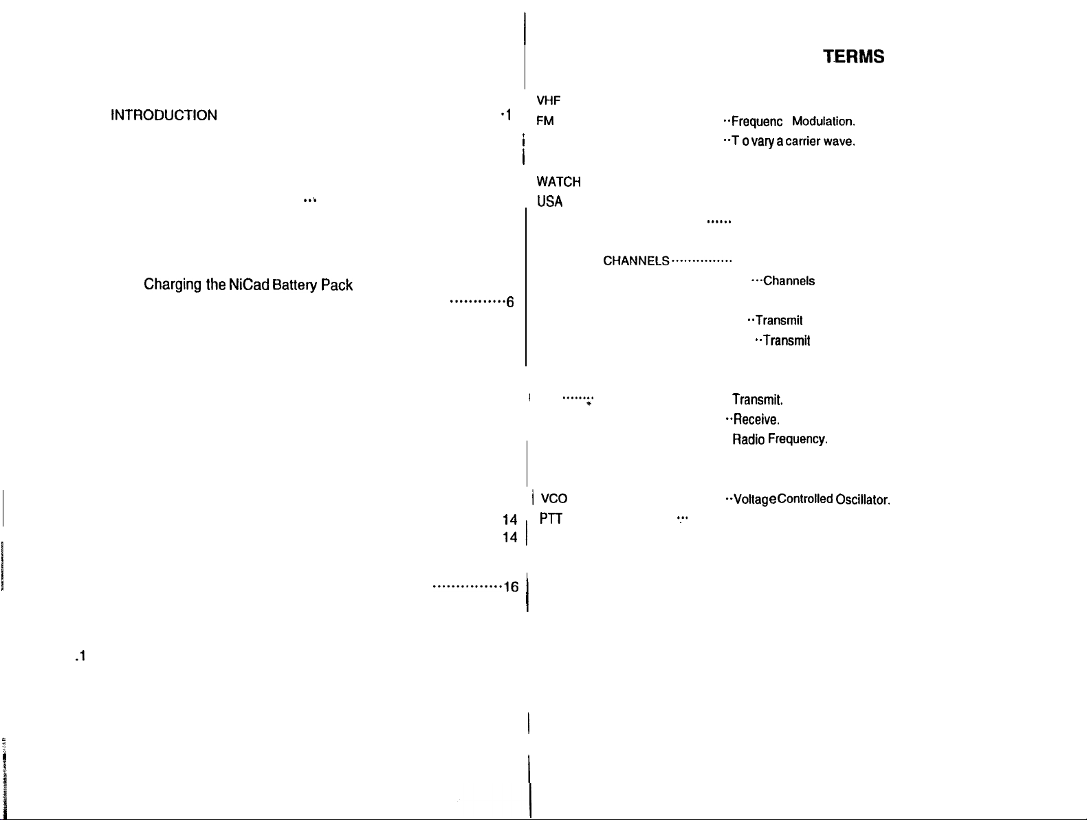
GLOSSARY OF T.ERMS
VHF
..........................................
FM
........................................
/
MODULATION
1 CARRIER WAVE ........................
WATCH
UsA
CHANNELS..
I
INTERNATIONAL CHANNELS
CANADIAN CHANNELS...............
WEATHER CHANNELS
SIMPLEX
DUPLEX
SQUELCH
..........................................
LCD
I
.....e~
’
TX
........................................
RX
..........................................
RF
.......................................
CPU
..........................................
PLL
......................... ..T 0
....................................
......................
. . . . . . . . . . . . ..-Channels for routine and emergency weather information
. . . . . . . . . . . . . . . . . . . . . . . . . . . . . . .
. . . . . . . . . . . . . . . . . . . . . . . . . . . . . . .
. . . . . . . . . . . . . . . ..*...*...........
..................................
.....................................
.:.
pj-T
............................
...........
I
I
I
Very High Frequency (30 MHz to 300 MHz)
..Frequen~
. radio frequency on which intelligence is superimposed.
Monitors channel 16 while working on another channel.
Channel designations as defined by the FCC.
..+..* Channel
Telecommunication Union.
Channel designations as defined by the Canadian Govt.
broadcast by NOAA.
To suppress totally.
Liquid Crystal Display.
Transmit.
y
Modulation.
vary a carrierwave.
designations as defined by the International
..Transrnit
..Transrnit
andreceive
on the
same frequency.
and receive on different frequencies.
..Receive.
Radio
Frequency.
Control Processor Unit.
Phase Locked Loop (A type of Frequency Synthesizer).
..Voltag e
Microphone Push-To-Talk switch.
Controlled Oscillator.
Page 4

SECTION 1
1.1
GENERAL
INTRODUCTION
DESCRIPTON
I
I
Congratulations on your purchase, of Raytheon RAY100 handheld marine radiotelephone. The
RAY100 is a CPU-controlled, digitally synthesized, compact handheld transceiver, that pro-
I
1
vides reliable simplex and duplex (two-frequency) communications between ships at sea and
from ships at sea to public or private shore stations. The RAY100 provides two-way communi-
I
cations on all U.S., International, and Canadian channel Marine band frequencies, plus
1Ition on 10 separate weather channels.
This manual describes the physical and functional characteristics of the radiotelephone.
I
recep-
1.2 EQUIPMENT FEATURES
I
The RAY 100 is designed and manufactured to provide ease of operation with excellent reliability. Some important built-in features of this radio are listed below:
l
Waterproof to U.S.C.G. standard CFR-46.
l
All solid-state circuitry for low current drain (longer battery life) and maximum reliability.
l
High-performance receiver section with optimum selectivity.
l
Access to all available U.S., International. and Canadian VHF Marine band channels.
l
Exclusive circuit that automatically selects CHf6 when the radio is turned on.
l
Exclusive weather alert feature (when in Monitor Mode).
. No limit for channels that can be programmed into memory for Memory Scan.
l
Selected channel number is always shown on the digital LCD display.
l
Aluminum die cast housing to prevent interference of offending RF.
l
“Quick” 16 PLUS, for instant. selection of the emergency calling channel CH16, or an
alternate priority channel.
l
I
Easy direct mode access to 10 weather channels WX 0 through WX 9.
Page 5

SECTION 2
INSTALLATION
!.I UNPACKING AND INSPECTION
Jse
care when unpacking your new RAY100 from the shipping carton to prevent damage to
he contents. It is also good practice to save the carton and the interior packing material. The
Jriginal
packing material should be used in the unlikely event it becomes necessary to return
he unit for service.
2.2
EQUIPMENT SUPPLIED
The following is a list of the standard equipment included with your RAYlOO.
Wall
Leatt.-.
NiCad
Descriotinn
----..r..“II
100 Radiotelephone
RAY
Ir
lstruction Manual
urger w/Bracket 11 OVAC
Ch;
N
iCad
Battery Pack
P
\A Battery Holder
rber
Helical Antenna
FiUk
inrette Carrying Case
_..
Iin
Belt Cl
w/Screws
‘I- .-.-----
kt .Stran
WI
.-. --.-r
ry
Safety Message
Bat&
-
Table 2-1 Equipment Supplied
I
I
I
I
1
Part No.
_ _.
_ .
-
M56801
G624698-5
G624698-2
G624698-1
G624698-4
G624698-6
G624698-7
G624698-8
G624700-9
G263695-1
1
‘I
I
1
1
2.3 ASSEMBLY
2.3.1 AA Battery Holder
I
Removal and Installation of this battery holder is as follows:
I) Using a coin or screwdriver, turn the screw at the base of the AA battery holder counter-
clockwise. This will allow you to remove the holder from the radio.
AA Battery Holder Removal
2)
There are no batteries installed in the AA battery holder from the factory. To install batter-
ies, carefully follow the battery insertion diagram found on the battery holder.
Installation of AA Batteries
2.2.1 Optional Accessories
Part
Descrlptfon
12V
Cigarette Lighter Adapter
High Gain Antenna
Leather Holster/Carrying Case
Soft Carrying Case
No.
E46002
M99-127
M99-128
M99-118
Table 2-2 Optional Accessories
These optional accessories may be ordered by calling our Customer Service Department
directly at (603) 647-7530 ext.2333 Monday through Friday 8:30 am-5:OO pm E.S.T.
I
AA BATTERY HOLDER USAGE
0
Always carefully note the correct lnstalfatlon of batterles Into the battery holder.
0
Only use Alkaline or
0
You may wish to use the AA battery holder as a “backup” battery pack, for use
should your
0
If rechargeable alkalines or NlCads are used, they must be removed from the AA
NlCad
NfCad
AA batteries in the AA battery holder.
pack become discharged at an lnconvenlent time.
battery holder to be recharged. The AA battery holder cannot be used with the
desktop charger included with your radio.
0
Always note the safety, handling, and storage lnstructlons that Is Included wlth
AA batteries you may purchase. Especlalfy when storfng batteries inside the AA
battery holder for extended periods of time, or emergency use.
-c-i-
Page 6

0
Since Alkaline batteries do not possess the power capacity of NlCad batteries, 2.3.2 NiCad Battery Pack
we
recommend uslng the 1 Watt power setting with this radio when the Alkaline
battery pack Is Installed. This
Your RAY100 also has the capability of calibrating the battery indicator for use with
Alkaline cells. To obtain an accurate representation of the level of the Alkaline batteries when the Alkaline pack is utilized, perform the following :
1. With the radio in an OFF condition, press and hold the MON keys.
2. Turn the radio ON.
. 3. “Al” will display on LCD. This indicates the battery indicator is calibrated for the
Alkaline Battery pack.
4. Turn the radio OFF to exit this setting mode.
will
Increase the life of your Alkaline batteries.
Remove the battery pack from the poly bag, and attach it to the radio housing. Using a coin or
screwdriver, turn the screw at the base of the NiCad battery pack clockwise to secure the
I
tery
to the radio housing.
I
I
bat-
installing the NiCad Battery Pack
The battery indicator is now calibrated for Alkaline cells. To re-calibrate for NiCa
fery
pack, perform the same steps as above and “Cd” will display in step 3 to indicade
NiCad calibration.
bat-
Note : Please confirm that the V mark on radio and battery pack Is matching.
2.3.3
Charging the NiCad Battery Pack
Although some voltage may be measured on the NiCad battery pack initially, it must be fully
charged before normal use.
1)
Insert the radio with the battery pack attached into the battery charger.
2)
Connect the AC wall adapter into a standard I IOVAC wall outlet.
3)
A typical time to recharge the battery pack can be up to 15 hours. Normal operating time
will be an average of 6 to 6 hours on a fully charged battery. To conserve battery life, use
the low (1 W) power setting when using the radio for primarily short range communications.
Charging the NiCad Battery Pack
Page 7

4
Getting the most out of your Nicad Battery Pack
>xtend the life of your NiCad Battery Pack
of
your
radio,
follow
the
guidelines listed below.
-echarge the radio’s
r radio
or an equivalent replacement.
radio
should always be turned OFF while recharging the battery
id short
charging cycles.
rged.
lid high
ambient temperatures (over 110°F) while recharging
en
the battery pack becomes warm to the touch, it is fully charged
n the charger.
le
radio
is to be stored for an extended period of time, remove the battery pack to avoid
;sible
damage
‘en it is
determined that the battery is no longer
5
Attaching the Antenna
:urely fasten
battery pack safely, always
fn
general,
and/or
resultant battery
the
rubber helical antenna to
and
maintain
the
battery should
failure.
useful, it
the
TNC type connector on the top of the
its
best performance during the
use Only the
AC adapter that comes with
Pack.
Only be recharged
the
battery
and
should be removed
should be disposed of properly.
pack.
when fully
dis-
radio.
(
2-3.6
I)2,put the
3, Attach
1
AtWdng
radio
Remove the
vided attach
the
wrist strap by looping it through
the Belt Clip and
into
the
supplied leatherette carrying case ff desired.
heft cffP
the belt
and hardware
clip to
the rear
BeIt
Clip and Wrist Strap Installation
WRI
STR
wrist
Strap
from the
housing of
packing matedals.
the radio.
the
mounting
hole.
Using
the
two
SCreWS pro-
Attaching the
Aitenna
I
Page 8

2.3.7 RAY1 00 Dimensions
Fig. 2-1 OUTLINE DIMENSIONS
SECTION 3
OPERATIONS
3.1 INTRODUCTION
Your RAY100 has the capability to transmit on all legally available Marine VHF radiotelephone
channels. There are channels that are FCC approved but may only be used by authorized stations for specific purposes, depending on the type of vessel (commercial or non-commercial).
Carefully review section 3.3.7 which lists all of the marine VHF channels available in your
RAY100 for U.S., International, and Canadian radiotelephone use. Full familiarization with this
table is essential when selecting your channels. The U.S. channels are those channels autho-
rized for use in the U.S. by the FCC. The international frequencies were agreed upon by the
attending countries at the 1966 International Telecommunication Union meeting in Geneva
and are in active use around the world.
3.2
CONTROLS AND LCD DISPLAY
Refer to Figure 3-1 for familiarization with the controls and display modes.
3.2.1 Controls
1) VOLUME Control (On/Off)
Turns the radio On and controls the Volume of the audio output from the speaker.
2) SQUELCH Control
Allows the user to “quiet” the receiver when no signals are being received.
3) PTT (Push-To-Talk) Switch
When pressed puts the radio into the transmit mode, and “TX” is displayed on the LCD.
4) SCAN I MEM Key
0 When pressed, puts the radio into the All scan or Memory scan mode. In this mode, the
radio scans through the channels, stopping when radio traffic is detected, then resumes
scanning after the traffic ceases.
and you wish to continue, press the SCAN I MEM key again to continue scanning.
0 When pressed and held for 1 second, the present channel will be programmed into
memory, or will be cleared from memory. The radio will beep to confirm when channels
are being stored or cleared from memory.
5) WX / INT Key
l
When pressed, selects the Weather
weather channel number (0 - 9).
weather channel. In the WX mode, the transmitter is disabled.
0 Press and hold for 1 second, to change from U.S. mode to INT (international) or CA
(Canada) mode. The U.S. mode is the default operating mode.
The INT and CA modes are not legal for use while operating in US waters.
If the scanning has stopped on a particular channel,
mode.“WX”
Use the Am channel keys to select your local NOAA
IMPORTANT NOTE
is displayed on the LCD along with a
Page 9

I MON /
IGPLUS Key
TXKey
l , When pressed, selects the Monitor mode and ‘MON” and
. this mode, the radio will monitor the currently selected working channel and the priority
channel
weather
l When pressed, and held for
power setting alternately changes between 5 and 1 Watt.
This key is used to instantly select the priority channel
priority channel from the factory. However an alternate channel can be programmed
as the priority channel if desired.
A/V
Channel Keys
The up and down arrow keys are used to change the currently selected channel. The
channel number is increased or decreased once with each keypress or if held, will
continue scrolling through the channels until released.
(16~1~s)
alert
broadcasts.
and also the last used weather channel is monitored for severe
1
second, a beep will be heard and the transmit output
‘wx
(16~1~s).
appear on the LCD. In
CH16 is the default
5
9
3
o-
Fig. 3-l LAYOUT OF CONTROLS
Page 10

.
‘3.2.2 ’
l&D
Display
A
&mber
describes each indicator and when it will appear.
I
@ MEM (Memory) : will be displayed when the current channel is a memory channel, and in
@I
SCAN (All Scan/Memory Scan) : will be displayed when the radio is In the All Scan or
a
MON (Monitor) : will be displayed when the radio is in the Monitor mode.
@I
WX (Weather) : will be displayed when a weather channel is selected. The “WX” indicator
@ INT (International) : will be displayed when International channels are programmed for
@I
5 I 1 : will be displayed to indicate the current TX power setting.
@ TX (Transmit) : will be displayed on the LCD when the Push-To-Talk (PTT) switch on the
@i
@ LARGE CHANNEL
@I
of indicators appear on the LCD display in different locations. The following list
L
Fig. 3-2 LCD DISPLAY
Memory Scan mode.
Memory Scan mode.
will blink when a severe weather alert tone is received (in Monitor mode).
use.
radio is engaged and the transmitter circuits are providing RF signals to the antenna.
BATT
:
is always shown on the display along with the battery voltage bar indicators to provide a battery level status. The “BATT” indicator will blink when the battery voltage is low,
and the battery needs charging. If a low battery condition is detected during transmission,
“LO” will be shown and the radio will stop transmitting. The battery level is shown on the
LCD as follows:
Battery conditlnn
Fully charged
Normal operation BATT --
Needs charging
SMALL CHANNEL
# : displays the channel number currently in use.
II
: displays the channel number of the priority channel in Monitor mode.
Other indicators shown in the Small Channel segment area:
C:
P:
indicates Canada mode.
indicates Priority mode.
LCD Indicator
BATT---
BAT-T --
1
3.3 OPERATING PROCEDURES
Specific operating procedures for the
regarding correct marine channel usage may be found in the Appendix section. Refer to the
Control section 3.2.1 beginning on page 9 for a thorough description of all RAY100 functions.
3.3.1 Turning the Power On
1) Rotate the ON/OFF/Volume control clockwise to turn the radio on. Continue rotating the
knob clockwise and set it at approximately the midpoint of it’s range.
2)
Rotate the SQUELCH control fully counterclockwise. (Background noise will be heard.)
3)
Set the VOLUME control to the desired listening level.
4)
Rotate the SQUELCH control slowly clockwise until the background noise in the speaker
ceases.
5)
When the power is initially turned on, the priority channel
the
Air
channel keys to select the desired working channel. Refer to section 3.3.7 on
pages 16 - 16 for the available VHF Marine channels and their frequencies.
RAY100
are presented in this section. General information
(16~1~s)
will be selected. Press
To Select A Weather Channel
1)
Press the WX / INT key, then the
channel (0 to 9). When the WX mode is selected, the transmitter is inhibited.
Al’l
channel keys to select your local NOAA weather
To Transmit
1)
To select or change the transmitter output power, press and hold the MON /
second. There are two output power settings: 5 Watts, and I Watt. The appropriate
power setting depends on the distance the message is to be transmitted, transmitting conditions, and desired battery life.
2)
Press the Push-To Talk (PTT) switch and speak into the microphone using a clear normal
voice.
l/5
key for 1
NOTES:
8
Initial
communication
contacts are usually made over channel 16 as all ships
and shore stations monitor this channel, then a shift to a worklng channel will
be necessary.
8 In certain US harbors and on certain channels, the FCC requires the
power to be
limited to 1 watt. On these “required” channels, the radio automatically selects
the 1 watt power output setting when the channel is selected.
8 The RAY100 is designed to meet the new FCC Rules Part 60.203, which states. if
the Push-To Talk (PTT) switch is
pre8Sed
for over five minutes continuously, the
transmitter will disengage. If this occurs, audible beeps will sound continuously
until the
PTT
switch is released. Upon release of the
PTT switch<
normal radio
operation will resume.
Page 11

\
. RAY1 00 Marine Channels and Their Usage
.3.7
‘e
.
I
Caution : Operation on channels not designated for use by your classification of craft, or
in lntematlonal or Canadian frequency mode while operating in US territorial waters is a
violation of FCC
ISA
Mode Frequency Table for the RAY100 VHF Radiotelephone
Rulea
and Regulations and may result in severe penalties.
2 I Watl
Inilially.
high power setting via
conlrols.
3:l
Wallonly.
4 : Not for use by general public.
Requires special aulhorizalion from
the U.S. Coast Guard, or under pd-
vate land mobile license.
5 : Channel 70 ls now used
Selective Calling only,
lransmission is disabled on chan-
net 70 In this radio.
“IMPORTANT NOTICE’.
I
,:
. . .,. ,.: . . . .
,a: ~~‘-y$q.5Hh0,)KI
User can override
Iron1
panel
lor Digsal
Iherefore
to
International Mode Frequency Table for the RAY100 VHF Radio
I
telephone.
Iwsai
1
: Transmlher is
aMed
In INT mode.
2
: 1 Wan Inillally. User
high power setting via front panel
controls.
_
3:i
Wanonly.
4 : Channel 70 Is now
SeleCllve
lransmlssion Is disabled on chan-
nel 70 In this radio..
**IMPORTANT
The INT mode ir not legal for use
while
operaling In U.S. waters The
TX/RX frequencies available in lhe
INT mode were agreed upon by the
4
attending countries ai
International Telecommunication
Union meeting In Geneva, and are
legal for
only.
,
;
I
I”I.“J”
161.700
.
V#nmslW”,IJ
Tns
Ins
-3
5
.-“.f
‘7rcial
--....
.
d
Pmn”-,al
Loast
Guard
‘0
0
Coast Guard
Coast Guard
;;;i
..,lor
I”,
f
f
f
f
,
I
f
f
f
f
f
f
$
f
, f
I f
I
on channels 15. 75. and 71
use
auloma~lcally dis
can
override
used
for
Drgilal
Calling only, therefore
NOTICE**
the
1966 ITU
In
Inlerna6onal waters
IC
-
I.”
I
f
n
f
f
f
f
- -
. . . . . . :::.:
:.:
Channels
3,21,23,61,64.61,62,
83,
(shaded) are not for use by
general public in U.S. walers. These
Irequencles may be used only under
authorization by the U.S. Coasl
Guard, or under private land mobile
license.
and
the
_. .-
ms
.I
I
I
! $
Page 12

.
t ’
ada
M,ohr Frhquency Table for the RAY 100 VHF Radiotelephone
I
-;
crllrftr
Mod.
=++=I
-1
j
Funcllon
.._
1 :
2 : 1 Walt
3:l
4 : Not
l tMPORTAHT NOTICE”
whilr operating in U.S. waters.
Transmiller
abled on channels
Canada mode.
high power selling
wnlrob.
Wattonly.
Requires special aulhorirallonlrom
Ihe Canadlan Coasl Guard. or
tmdwphPmMmobile-.
Canada mode Is not legal for use
Is aulomalically
15.75.and
Inilially.
User can
lor
use by general public.
overrlde
via
Iron1 panel
dls-
76 in
lo
,
I
I
I
’
4.1
4.1
i
SPECIFICATIONS
.l
Transmitter
Channels
Frequency Stability
Frequency Range
Channel Spacing
Power Output
Modulation
Modulation Audio
FM Hum & Noise
Audio Distortion
Spurious 8 Harmonic
Antenna Impedance
Transmitter Protection
SECTION 4
SPECIFICATIONS
All available
*lo
PPM (0.001%) from -20°C to
156.025 to 157.425 MHz
25 KHz increments
Switchable
Frequency Modulated
Shall not vary+l/-3 dB from true 6
emphasis response from 300 to 2500 Hz, refer
ence 1000 Hz. Audio frequencies 3-20 KHz shall
be attenuated (at 1 KHz by 60 log
20 KHz by 50
Level greater than 40 dB below audio
Less than 10% at 1 KHz for3 KHz deviation
Attenuated at least
ated carrier power) per FCC, Rules Parts 2 8 60
50 Ohms
Shall survive open or short circuit of antenna
system without damage (10 min. test)
5W,
USJNT,
Canada VHF Marine band
+5o”C
1 W into 50 Ohms at 6.0 VDC
(16KOG3E)
dB/Oct prey
f/3 dB.
dB)
43+10
log PO (below rated radi-
Above
Ins
il
or
Marine Operator
mmerdal
il 5
II
Receiver
4.1.2
/
Channels
Frequency Range
I
Frequency Stability
Usable Sensitivity
Squelch Sensitivity threshold
Tighl squelch sensitivity
Modulation Acceptance
Adjacent Channel Rejection
Spurious Image Rejection
Intermodulation Rejection
Audio Output
All available
USJNT,
Canada VHF Marine band
156.025 to 163.275 MHz in 25 KHz increments
ilO
PPM (0.001%) from -20°C to
+5o”C
0.3 UV for 12 dB (SINAD); 0.5 UV for20 dB quieting
0.3 UV or better
0.5uv to 1 .ouv
Less
thank7.0
Greater than 65
Greater than 65
Greater than 60
0.4 Watt or more at 10% or less
KHz
dB
dB
dB
di6lOItiOn
into
41
Ohm load
Hum & Noise in Audio
Less than -40 dB
J
4
J
/
Page 13

I
.1.3 *
Dierafing Requirements
p
**Input Voltage
Battery Capacity
‘Current Required
Transmit
Receiving (squelched)
Operating Temperature
Duty Cycle
Humidity
6.0 VDC NiCad rechargeable battery
6OOmAIH
Less than 2.0 amps at 5 W; and 1 .O amp at 1 W
Less than 40mA; 150mA at 0.3 Watt audio output (1 KHz)
-20°C to
+5o”c
Continuous, 60% receive, 20% transmit (max. 10
min.
@25)
100% at
+50X
for 6 hours
SECTION 5
APPENDIX
5.1
VHF MARINE CHANNEL USAGE GUIDE AND LICENSING REQUIRE?
MENTS
Most of the information found in this
Information Bulletin No. 2 REVISED EDITION February 1991 and FCC Fact Sheet
5000 March 1990.
REMEMBER:
secllon
is reprinled in whole or in part from FCC
PR-
.1.4
Radio Dimensions
Height (radio body w/batt.)
Width
Depth
Weight
The RAY1 00 VHF FM Radiotelephone meets all applicable sections of
149.2 mm
63.3
36.0
Approx. 0.5kg. (1 lb)
NOTE:
FCC Rules Parts
2,15
mm
mm
and 80.
l Maintain a radio walch on Channel 16. Channel 16 is used for disltess and
safety purposes
l Use VHF Channel 70 only for Digital Selective Calling (DSC). It may be used
a.
for general-purpose calling using DSC. Your cooperation in not using Channel
70 for general intership communications is necessary to prevent interference.
l Your VHF transceiver has a high-low power switch. Use low power whenever
feasible. Unnecessary high-power operations can interfere with other important communications.
l Always use your radio calf sign at the beginning and end of each transmission.
l Be sure only qualified persons operate your radio. You are responsible for con-
trol of your radio. Know the rules.
l Limit calls to other vessels to 30 seconds. If you receive no reply, wait 2 min-
utes; then-try again. Keep communications brief and avoid chit-chat.
l Never transmit false distress messages, and never use profanity on the air.
OTHER REMINDERS:
You need a radio operator license to operate VHF Marine Radio only if you plan 16 dock
in a foreign port or leave a foreign port to dock in a U.S. port.
l Your radio license is not transferable. If you sell your boat, request the FCC to
-
cancel your station license.
 Loading...