

Page 1

DSM250
Digital Sounder
Module
Owner’s
Handbook
Document number: 81211_1
Date: December 2002
Page 2

Page 3

DSM250 Digital Sounder Module iii
DSM250 Digital Sounder Module Owner’s Handbook
December 2002
Intended Use
Raymarine DSM250 Digital Sounder Modules provide echo
sounder data that can be displayed on Raymarine PLUS Radar,
Chartplotter, or Fishfinder display units. DSM250 Digital
Sounder Modules are intended for recreational depth finding and
fishfinding purposes.
SAFETY NOTICES
This equipment must be installed and operated in accordance with
the instructions contained in this manual. Failure to do so can
result in personal injury and/or navigational inaccuracies. In particular:
HIGH VOLTAGE. The DSM250 contains high voltages. Adjustments require specialized service procedures and tools only available to qualified service technicians – there are no user
serviceable parts or adjustments. The operator should never
remove the cover or attempt to service the equipment.
CAUTION:
Removing the transducer cable from the rear of the DSM250
while the sounder module is powered on can cause sparks. Only
remove the transducer cable after power has been removed from
the DSM250. As with any electronic device, be sure the sounder
module is mounted where it is well ventilated and free from
gasoline fumes.
If the transducer cable is accidentally removed while the DSM250
is powered on, remove power from the sounder module, replace
the transducer cable, and then return power to the module. As a
safety feature, the DSM250 only recognizes that the transducer is
connected at power-up.
Page 4

iv DSM250 Digital Sounder Module
EMC Conformance
All Raymarine equipment and accessories are designed to the best
industry standards for use in the recreational marine environment.
The design and manufacture of Raymarine equipment and accessories conform to the appropriate Electromagnetic Compatibility
(EMC) standards, but correct installation is required to ensure that
performance is not compromised.
Preface
This handbook describes the Raymarine DSM250 Digital
Sounder Module (200/50 kHz).
This device must be connected to an
ter, or Fishfinder display unit to show echo sounder data. The
DSM250 will not work with older HSB (non-PLUS) displays.
Note: Older HSB (non-PLUS) display units must be upgraded to
before they can function with the DSM250.
Echo sounder systems require an appropriate Raymarine transducer unit and inter-connecting cable. Details for selecting and
installing the transducer are described in document number
81196, Transducers for Fishfinders Owner’s Handbook.
2
hsb
PLUS Radar, Chartplot-
hsb
2
This handbook contains very important information on the installation and operation of your new equipment. In order to obtain the
best results in operation and performance, please read this handbook thoroughly.
Raymarine’s Technical Services representatives or your local
dealer will be available to answer any questions you may have.
Conventions
Raymarine echo sounding (sonar) devices with integrated displays are known as Fishfinders. In this document, the DSM250—
which does not have its own display—is alternatively called a
Digital Sounder Module, Sounder, or just Module. The DSM250’s
image data can be viewed on a display unit when that display is in
Sonar Mode.
Page 5

DSM250 Digital Sounder Module v
Throughout this handbook, the dedicated (labelled) keys are
shown in bold capitals; for example, MENU. The soft key functions, menu names and options are shown in normal capitals; for
example, SCREEN.
Operating procedures, which may consist of a single key-press or
a sequence of numbered steps, are indicated by a ➤ symbol in the
margin. When the procedure requires you to press a soft key, the
soft key icon is shown in the margin.
Technical Accuracy
The technical and graphical information contained in this handbook, to the best of our knowledge, was correct as it went to press.
However, the Raymarine policy of continuous improvement and
updating may change product specifications without prior notice.
As a result, unavoidable differences between the product and
handbook may occur from time to time, for which liability cannot
be accepted by Raymarine.
Warranty
To register your DSM250 Digital Sounder Module ownership,
please take a few minutes to fill out the warranty registration card
found at the end of this handbook. It is very important that you
complete the owner information and return the card to the factory
in order to receive full warranty benefits.
Raymarine Products and Services
Raymarine products are supported by a network of Authorized
Service Representatives. For information on Raymarine products
and services, contact either of the following:
United States Raymarine, Inc.
22 Cotton Road, Unit D
Nashua, NH 03063-4219
USA
Telephone:1-603-881-5200
1-800-539-5539
Fax: 1-603-864-4756
Page 6

vi DSM250 Digital Sounder Module
Europe Raymarine Ltd
Anchorage Park
Portsmouth, Hampshire
England PO3 5TD
Telephone: +44 (0) 23 9269 3611
Fax: +44 (0) 23 9269 4642
Or, you may contact us on the World Wide Web at:
www.raymarine.com
This product contains technology provided under license by
Acorn Group plc. The copyright of this intellectual property is
acknowledged by Raymarine, Inc. as are Acorn’s trademarks and
patents. Acorn’s world wide web address is www.acorn.com.
Raymarine is a registered trademark of Raymarine Limited.
SeaTalk is a registered trademark of Raymarine Limited.
2
hsb
is a trademark of Raymarine Limited.
Pathfinder PLUS is a trademark of Raymarine Limited.
© Raymarine, Inc. 2002
Page 7

DSM250 Digital Sounder Module vii
Contents
SAFETY NOTICES ........................................................iii
EMC Conformance .......................................................... iv
Warranty ............................................................................ v
Raymarine Products and Services ..................................... v
Chapter 1: Overview .................................................................. 1-1
1.1 Introduction .......................................................... 1-1
How to Use This Handbook ...........................................1-2
What's New ....................................................................1-3
General ...........................................................................1-4
Sonar Mode Display Features ........................................1-5
1.2 Sonar Mode Display ............................................. 1-5
Operating Modes ...........................................................1-7
Sonar Options ................................................................1-8
Sounder Functions .........................................................1-9
Chapter 2: Installation .............................................................. 2-1
2.1 Introduction .......................................................... 2-1
Planning the Installation ................................................ 2-2
EMC Installation Guidelines .........................................2-2
2.2 Unpacking and Inspecting the Components ......... 2-4
2.3 Selecting the Equipment Location ........................ 2-4
Sounder Module Mounting Location ............................2-4
2.4 Cable Runs ............................................................ 2-5
2.5 Mounting the Sounder Module ............................. 2-8
2.6 System Connections ............................................. 2-9
DC Power Connection .................................................2-10
Ground Connection ......................................................2-11
2
hsb
Connection ............................................................2-12
Transducer Connection ................................................2-13
Page 8

viii DSM250 Digital Sounder Module
EMC Conformance ......................................................2-15
Chapter 3: Getting Started ....................................................... 3-1
3.1 Introduction ...........................................................3-1
3.2 Powering on the Sounder Module ......................... 3-1
Status LED .....................................................................3-1
3.3 Updating Software on the Display Unit ................3-2
3.4 Selecting Repeater Mode ......................................3-2
3.5 Selecting Sonar Mode ...........................................3-3
3.6 Simulator Mode .....................................................3-5
Viewing Simulator Data .................................................3-6
Chapter 4: System Setup ........................................................... 4-1
4.1 Introduction ...........................................................4-1
4.2 Changing the Set Up Parameters ...........................4-1
4.3 System Set Up Parameters ....................................4-3
Data Boxes .....................................................................4-5
Bearing Mode .................................................................4-6
Cursor Reference ...........................................................4-6
Cursor Readout ..............................................................4-6
Day/Night ......................................................................4-6
Help ................................................................................4-7
Soft Keys ........................................................................4-7
Key Beep ........................................................................4-7
MOB Data ......................................................................4-7
Autopilot Pop Up ...........................................................4-7
Menu Timeout Period ....................................................4-7
Units ...............................................................................4-8
Variation Source .............................................................4-8
Bridge NMEA Heading .................................................4-9
NMEA-Out Set Up ........................................................4-9
Cursor Echo .................................................................4-11
Page 9

DSM250 Digital Sounder Module ix
Date and Time Settings ................................................4-11
GPS SOG/COG Filter ..................................................4-12
Compass Set Up ...........................................................4-12
Language ......................................................................4-12
Simulator ......................................................................4-12
4.4 Sonar Set Up Parameters ..................................... 4-13
Target Depth ID ............................................................4-14
Color Bar ......................................................................4-14
Depth Digit Size ...........................................................4-14
Sonar HSB Mode .........................................................4-14
Depth Offset .................................................................4-15
Speed Calibrate ............................................................4-16
Temperature Calibrate .................................................4-16
Sonar History ...............................................................4-16
Sonar Interference Rejection .......................................4-16
Sonar Simulator ...........................................................4-17
Version/Serial Numbers ...............................................4-17
Chapter 5: Basic Display Controls ............................................ 5-1
5.1 Introduction .......................................................... 5-1
Simulator ........................................................................5-1
5.2 Setting Color and Brightness ................................ 5-1
Lighting and Contrast (Monochrome Displays) ............5-1
Brightness and Color Settings (Color Displays) ............5-2
5.3 Controlling the Display ......................................... 5-5
Selecting the Display Mode ...........................................5-6
Switching Between Sounder and Other Modes ...........5-12
5.4 Display Control Functions .................................. 5-13
Viewing Data Boxes ....................................................5-14
Changing the Scroll Speed ...........................................5-14
Selecting the Power Setting .........................................5-15
Changing the Sounder Range ......................................5-16
Selecting the Frequency ...............................................5-19
Using Bottom Lock ......................................................5-20
Using A-Scope .............................................................5-22
Page 10

x DSM250 Digital Sounder Module
Using Zoom .................................................................5-24
Chapter 6: Sonar Mode Operation ........................................... 6-1
6.1 Introduction ...........................................................6-1
6.2 Interpreting and Adjusting the Sounder Image .....6-1
Fish Indications ..............................................................6-2
Bottom Indications .........................................................6-3
Using White Line ...........................................................6-5
Adjusting Display Gain (Sensitivity) .............................6-5
Using Alarms .................................................................6-8
6.3 Using VRM to Determine Depth & Distance from
Vessel ...................................................................6-10
6.4 Waypoints ............................................................6-12
Placing a Waypoint ......................................................6-13
6.5 MOB ....................................................................6-14
Chapter 7: Maintenance and Problem Solving ...................... 7-1
7.1 Maintenance ..........................................................7-1
Routine Checks ..............................................................7-1
Cleaning Instructions .....................................................7-1
EMC Servicing and Safety Guidelines ..........................7-2
7.2 Resetting the System .............................................7-3
7.3 Problem Solving ....................................................7-4
Status LED .....................................................................7-6
How to Contact Raymarine ............................................7-7
Worldwide Support ......................................................7-10
Appendix: Specifications ........................................................A-1
Page 11
Chapter 1: Overview 1-1
Chapter 1: Overview
1.1 Introduction
This handbook describes the DSM250 Digital Sounder Module.
The DSM250 receives sonar signals from a transducer mounted in
the water and transmits data via
or Chartplotter display unit already installed in your vessel, eliminating the need for a separate display unit. You may also connect
the module to an existing PLUS Fishfinder display for improved
performance.
Note: Older HSB (non-PLUS) display units must be upgraded to
before they can function with the DSM250.
2
hsb
to a Pathfinder PLUS Radar
hsb
2
-1
9
5
1
6
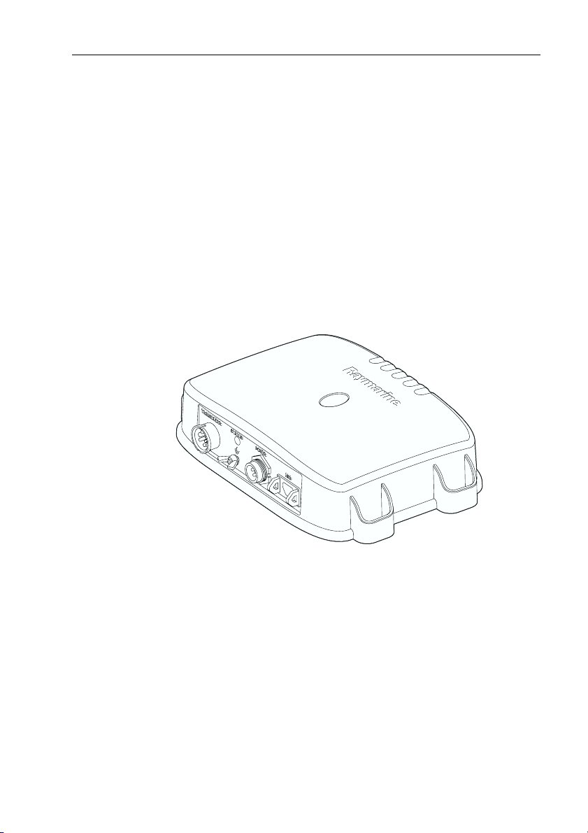
D
Figure 1-1: DSM250 Digital Sounder Module
The DSM250 employs a very high transmission repetition or
“ping” rate which, along with the digital adaptive high sample
rate receiver, ensures that fish and bottom structure are presented
in superb detail and optimal color allocation (in color LCD displays). The DSM250 digital bandwidth adaptation adjusts the
receiver band width dynamically from very wide to very narrow,
as required by the actual water conditions. This provides superior
fish and bottom detection in conditions where other fishfinders
see very little or nothing at all.
Page 12

1-2 DSM250 Digital Sounder Module
The DSM250 features dual frequency (200 kHz and 50 kHz)
operation and—depending on the transducer installed and conditions—up to 1000 watts RMS output power and performance
from 3 ft (1m) up to 5000 ft (1700 m).
This handbook describes DSM250 functions and how to use
hsb
PLUS Radar, Chartplotter, or Fishfinder display unit controls to
operate sonar operations. Controls that are specific to either
Radar, Chartplotter, or Fishfinder display unit functions are not
described in this document but can be found in the handbook for
that display.
Note: Many illustrations in this handbook show example screens.
The screen you see on your display depends on your system configuration and set up options, so it may differ from the illustration.
How to Use This Handbook
If you are installing the DSM250 yourself, you should read
Chapter 2 before you start the installation.
For an overview of the display unit controls, read Chapter 5.
Chapter 3 will help you start using your system.
For detailed information on sounder module operations, refer to
Chapter 6.
2
To change the system set up default settings, read Chapter 4.
Chapter 1 gives an overview of the display unit controls and
sonar operation.
Chapter 2 provides planning considerations and detailed instructions for installing the DSM250 and connecting the unit to the display unit via
hsb
2
.
Chapter 3 provides instructions for setting up your system to suit
your preferences. You should read this chapter to determine how
to change the sonar system from the default settings.
Chapter 4 shows how to start using the display and viewing sonar
echo data.
Chapter 5 details operating the display unit’s controls in Sonar
mode.
Page 13

Chapter 1: Overview 1-3
Chapters 6 provides detailed information for operating the sonar
functions - selecting depth range limits, adjusting gain, color and
STC, setting alarms, using the VRM marker, marks and man overboard.
Chapter 7 provides information on user maintenance, and what
to do if you experience problems.
The Appendix lists the technical specifications for the DSM250.
What's New
The DSM250 operates much like traditional Raymarine fishfinders. If you are already familiar with our displays, you won’t have
much difficulty using the DSM250. Below is a list of DSM250
features that differ from our traditional fishfinder displays.
• No integral display. You connect the DSM250 to an
Radar, Chartplotter, or Fishfinder display unit to show echo
sounder data.
• Digital sonar. The DSM250 employs a digital dynamic adaptive
receiver and transmitter for dramatically improved fish and bottom detection in any water conditions.
• New automatic Gain modes. These automatic modes make the
gain adjustments for you, based on depth and water conditions.
The DSM250 provides three pre-defined automatic gain settings
for Cruising, Trolling, and Fishing. See Adjusting Display Gain
(Sensitivity) on page 6-5.
• Bottom hunt feature. The DSM250 features a digital “Hunt
mode” that automatically searches for the bottom when the
sounder is in Auto Range. Unlike our fishfinder displays, the
DSM250 stays in manual range when placed there—it does not
switch to auto mode by itself. When you are trying to automatically find bottom, you need to have the sounder module set to
Auto Range mode. Refer to Hunt Mode on page 5-18.
• Auto frequency. When set to Auto Frequency, the DSM250 also
alternates frequencies when hunting for bottom. If set for Manual
frequency, the unit does not switch frequencies when bottom
hunting. This differs from traditional Raymarine fishfinder displays. Details are found in Selecting the Frequency on page 5-19.
• New Auto STC mode. You can now let the sounder unit automat-
ically choose the optimal STC level for reducing background
noise that often appears in shallow water. See STC on page 6-8.
hsb
2
PLUS
Page 14
1-4 DSM250 Digital Sounder Module
• Transducer detection. For safety reasons, if the transducer is
disconnected and then reconnected while the sounder is powered
on, the DSM250 does not detect that the transducer has been reattached. In this case, you must power down the DSM250, reconnect the transducer cable, and then power the sounder module
back on before it operates properly.
• Status LED. The LED on the connector panel provides valuable
status information. The LED blinks green while the module is
operating normally. If the unit detects a problem, the LED blinks
amber to indicate a warning or red for an error. The number of
times the LED blinks is a code representing the nature of the problem. Refer to Status LED on page 7-6.
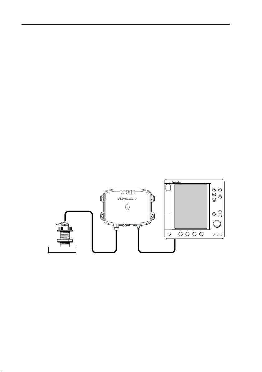
General
The DSM250 system, illustrated below, is comprised of the Digital Sounder Module, an
2
hsb
PLUS Radar, Chartplotter, or Fish-
finder display unit, transducer, and associated cables.
Transducer
Digital Sounder Module
hsb
2
2
hsb
PLUS Display Unit
Figure 1-2: Basic Echosounder System using the DSM250
The DSM250 module is waterproof to CFR46 and can be installed
either above or below deck.
The unit includes connections to:
• power
• the transducer
• the display unit, via
hsb
2
• ground
D6160-1
Page 15

Chapter 1: Overview 1-5
Transducer
The DSM250 requires a transducer, mounted either thru-hull, inhull, or on the transom.
Transducers can measure water depth, and if so equipped, temperature, distance traveled, and/or speed. It is important to position
your transducer correctly. For details on transducers, including
location and installation instructions, see document number
81196, Transducers for Fishfinders Owner’s Handbook.
Note: If speed, temperature, or distance travelled are being input to
the display unit via SeaTalk, the SeaTalk value is displayed instead of
the value transmitted by the DSM250.
Sonar Mode Display Features
When connected to a display unit and switched to Sonar mode,
the following data can be viewed:
• Depth, speed, and temperature, if the transducer is so equipped
• Single or split frequency sonar display – 50 kHz, 200 kHz
• Display options – sonar window, zoom, bottom lock, and AScope
• Horizontal and vertical half-screen windows to display additional
data. Position data requires GPS.
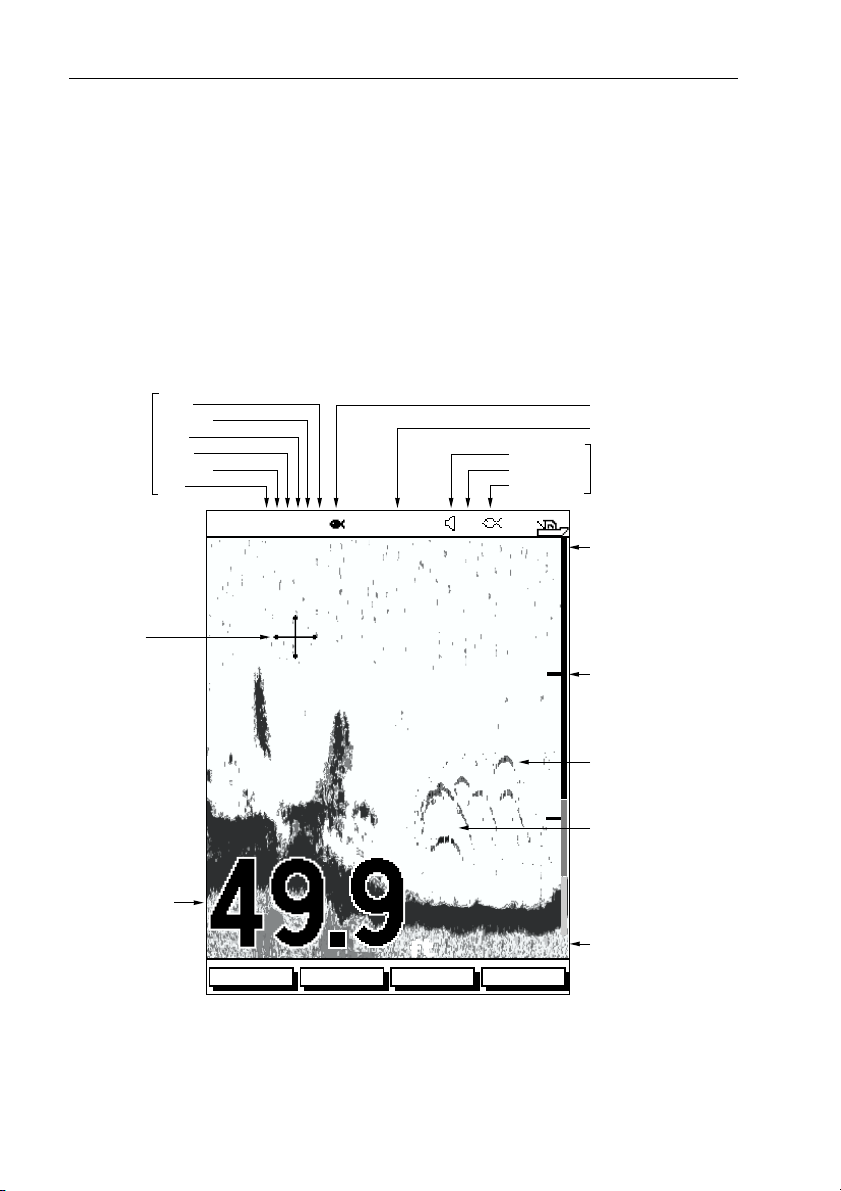
1.2 Sonar Mode Display
When you first switch the display unit into Sonar mode, the
scrolling bottom graph is displayed. This is a graphical representation of the echoes seen by the DSM250. As time passes, this display scrolls from right to left and becomes a record of the echoes
seen. A typical display is shown in Figure 1-3 .
The images at the right hand side of the display are the most
recent echoes. Some echoes indicate fish, and others show the
bottom. It can also indicate bottom structures, such as a reef or
shipwreck. The upper and lower depth range limits are shown.
The sonar screen includes a status bar that displays transducer frequency and indicates which auto settings are enabled (Gain, Color
Gain, Range, Zoom and Frequency), and alarm status (fish and
shallow/deep water depths).
Page 16
1-6 DSM250 Digital Sounder Module
You can customize the sounder by choosing what is displayed and
how it is displayed (including language and units). For example,
you can set the scroll speed of the bottom graph display, and you
can select the range to adjust the depth displayed.
You can view the cursor position and a variety of data (such as
speed and depth) from the transducer and other equipment in userselectable data boxes. These data boxes can be moved around the
screen and they can be switched on or off.
Chapter 3 includes details on adjusting the display, other set up
options are described in Section 4.4.
Auto
Mode
Indicators
Power
Frequency
Zoom
Range
Color gain
Gain
Alarm enabled
Shallow, Deep
Fish
Target Depth ID On
Frequency
Alarm
Indicators
Cursor,
controlled
by trackpad
Bottom depth
AUTO GCRZFH
18
50kHz
22
38
36
35
42
SD
33
36
32
37
ft
ZOOMFREQUENCY
BTM.LOCK A-SCOPE
Figure 1-3: Typical Display in Sonar Mode
20
40
Water surface
0
Depth markers
Target image (fish arch)
Target image depth
Range
60
D6181-1
Page 17

Chapter 1: Overview 1-7
Operating Modes
Depending on the types of display(s) you have connected via
up to four full-screen modes – sonar, chart, radar, and data log are
available. You select the operating mode using the DISPLAY key
as described in Chapter 3.
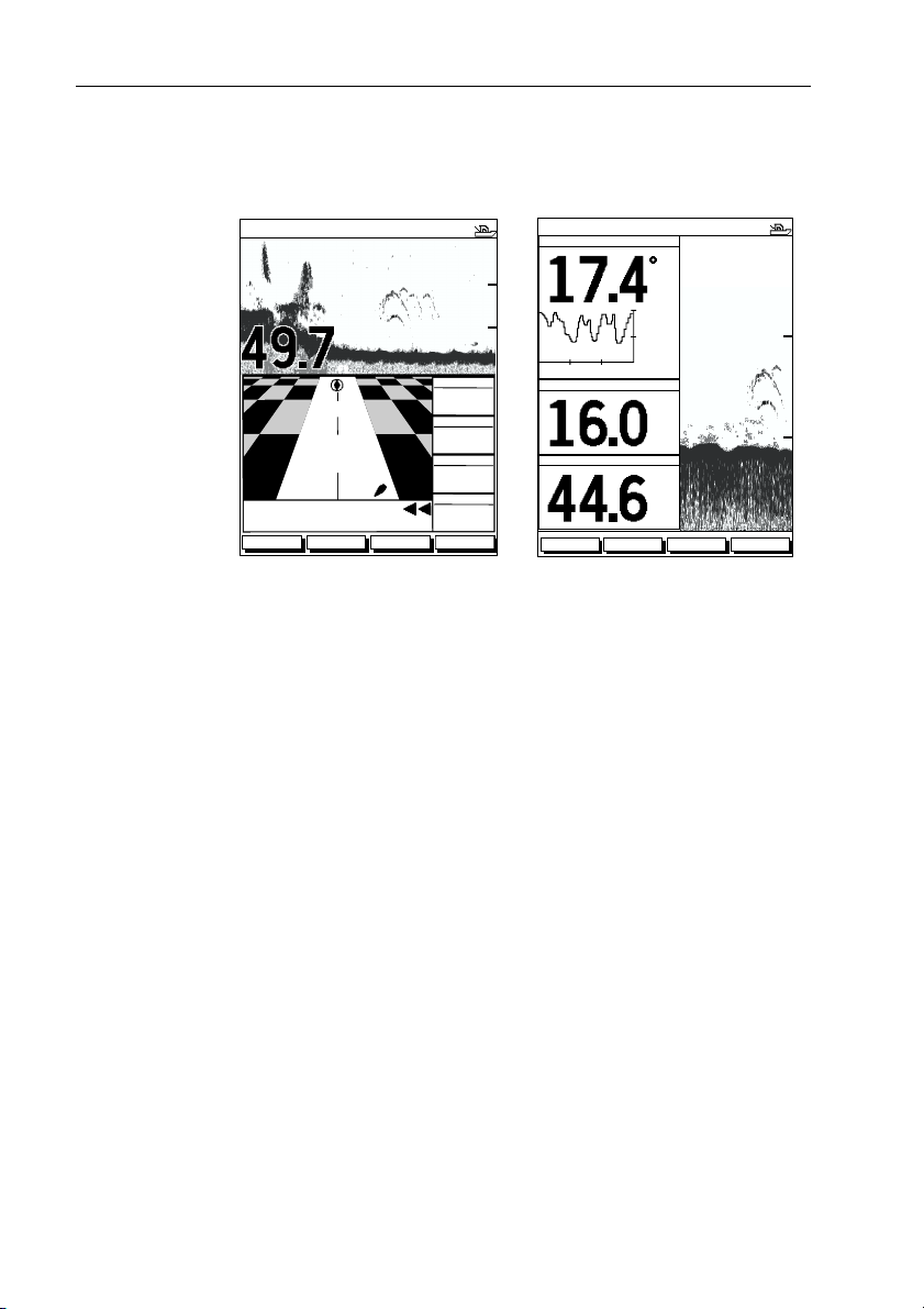
You can also set Windows On to split the display into two half-
screen windows (horizontal or vertical) to show supplementary
data, or to display sonar and chart or radar simultaneously.
Horizontal Half -Screen Window Options
Using horizontal half screens, the main operating mode is displayed in the upper window; you choose what is displayed in the
lower window. The following information, if available on your
system, can be shown:
Table 1-1: Horizontal Half-Screen Window Options
Full-screen
mode Horizontal Half-Screen Window Options
hsb
2
,
Sonar Mode Course Deviation Indicator (CDI), Bearing and Distance
Chart Mode CDI, BDI, Navigation Data (databoxes), Radar, Sonar
Radar Mode CDI, BDI, Navigation Data, Chartplotter, Sonar
Data Log Mode Half-screens not available
Indicator (BDI), Depth/Temp graph, Chart plotter, Radar
Vertical Half -Screen Window Options
This option splits the sounder vertically. The left hand window displays data boxes; there are three different sets of data (A, B, and C)
that you can select for display. The following information is available only in Sonar Mode:
Table 1-2: Vertical Half-Screen Window Options
Full-screen
mode
A Temperature, Speed, Depth
B Position (latitude and longitude), Course Over Ground
C Waypoint Range and Bearing, COG, SOG, Depth
Vertical Half-Screen Window Options
(COG), Speed Over Ground (SOG), Depth
Page 18
1-8 DSM250 Digital Sounder Module
Note: Receiving and displaying position data requires that a GPS is
connected to your Raymarine system.
Horizontal Half-Screen
AUTO GCRZFH
50kHz
ft
XTE
0.28nm
WPT BRG
351°T
WPT RNG
0
20
40
60
Vertical Half-Screen
AUTO GC FH
TEMPERATURE
30 0MINUTES
50kHz
20.1
15.1
10.1
SPEED
DEPTH
F
kts
0
20
40
26.8nm
STEER PORT
WAYPOINT 001
ZOOMFREQUENCY
BTM.LOCK A-SCOPE
03
TTG
h:59m
ft
ZOOMFREQUENCY
BTM.LOCK A-SCOPE
60
60
D6206-1
Figure 1-4: Half-Screen Windows in Sonar Mode
Details on selecting windows are given in Chapter 3.
For details on the radar, chartplotter or fishfinder display, please
refer to the Owner’s Handbook supplied with that unit.
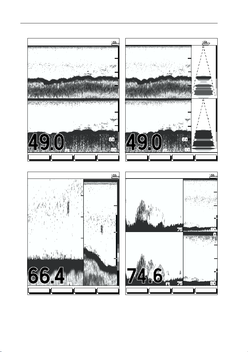
Sonar Options
The DSM250 provides controls to select additional modes:
• Frequency – you can select the transducer frequency: 50 kHz for
wide coverage and deep water, 200 kHz for a detailed view, both
frequencies simultaneously or auto-frequency. The default setting is auto-frequency, which determines the optimum frequency
of operation based on the current depth.
• Bottom Lock – changes the operating mode to re-set the bottom.
It provides a bottom-up view: the bottom is used as the reference,
its image is flattened and depths are displayed here.
Bottom lock mode is used primarily to filter out the bottom structure and display fish details only.
• A-Scope – displays a real-time image of the bottom structure and
fish directly below the transducer. The A-Scope window also displays the patented Bottom Coverage width indication.
Page 19

Chapter 1: Overview 1-9
• Zoom – enlarges all or part of the bottom graph display. You can
select x2, x4, or x6 magnification and the zoom area can be automatically or manually adjusted.
You can select the Zoom or Bottom Lock image to be displayed in
place of the regular bottom graph display. Alternatively, you can
set the display window to be split vertically with the bottom graph
displayed in the right hand screen and the Zoom or Bottom Lock
image displayed in the left hand screen. See Figure 1-5 .
If you choose dual frequency, the scrolling bottom graph is displayed in both frequencies, split horizontally. Zoom, Bottom
Lock, or A-Scope can be displayed with the dual frequency graph.
All of these options are available when the sonar data is displayed
in a half-screen window.
Sounder Functions
The DSM250 includes the following functions:
• Automatic or manual selection of scroll speed for bottom graph
display
• Automatic or manual selection of transducer frequency
• Automatic or manual selection of depth range limits
• Automatic or manual selection of Gain, Color Gain, and STC settings
• Set up alarms for Fish, Shallow water and Deep water
• VRM marker to determine depth and distance
Operation of these functions is described in Chapter 3 and
Chapter 6.
Page 20
1-10 DSM250 Digital Sounder Module
AUTO GC Z H
SPLIT
0
20
AUTO GC Z H
SPLIT
0
20
40
60
200kHz
200kHz
50kHz
50kHz
ft
ZOOMFREQUENCY
Split Frequency Split Frequency with A-Scope
AUTO GC Z H
BTM.LOCK A-SCOPE
200kHz
80
0
20
40
60
80
200kHz
200kHz
50kHz
50kHz
AUTO GC Z H
ft
ZOOMFREQUENCY
SPLIT
0
30
20
20
200kHz
40
10
200kHz
50kHz
40
60
80 6.8
0
20
40
60
80
27.2
27.2
BTM.LOCK A-SCOPE
55
20
40
60
75
55
20
0
80
0
BL
0
ft
ZOOMFREQUENCY
Bottom Lock Split with Bottom Graph Zoom Split with Split Frequency
BTM.LOCK A-SCOPE
60
80
80
X4
ft
ZOOMFREQUENCY
Figure 1-5: Sonar Display Options
40
60
75
BTM.LOCK A-SCOPE
80
D6202-1
Page 21
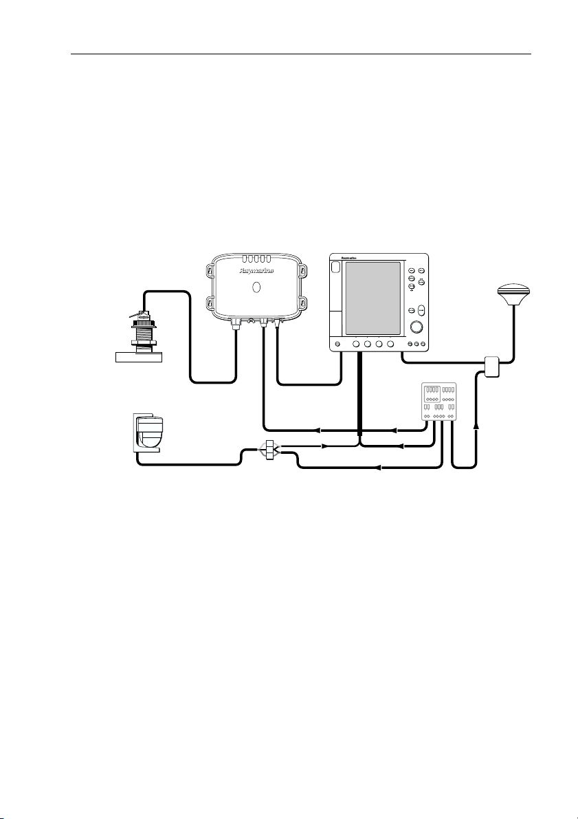
Chapter 2: Installation 2-1
Chapter 2: Installation
2.1 Introduction
This chapter provides installation instructions for your DSM250.
Basic systems, such as that in Figure 2-1 below, are explained.
Details for mounting the DSM250 and connecting the equipment
are included.
Transducer
Compass
Digital Sounder Module
hsb
12/24V Supply
2
hsb
PLUS Display Unit
GPS
Junction
SeaTalk
2
Distribution Panel
Box
D6164-1
NMEA
12/24V Supply
12V Supply
12V Supply
Figure 2-1: DSM250 in an Integrated System
Note: If you wish to practice using the unit before installation, connect the HSB cable to a PLUS display unit and use the simulator mode
as described in Chapter 3. For power, connect a 12V or 24V DC
power supply, attaching the red wire via a quick blow 8A fuse to positive and the black wire to negative. See Section 3.6 for details.
For the system to display depth, water temperature and speed, you
must install the transducer type(s) capable of transmitting the
appropriate data.
For full functionality of the radar and chartplotter you need to provide position and heading data. For details, refer to the handbooks
for those products.
Page 22

2-2 DSM250 Digital Sounder Module
Planning the Installation
Before you install your system, plan the installation, considering:
• Correct transducer for your application. See document number
81196, Transducers for Fishfinders Owner’s Handbook.
• Location of the display unit, as described in Section 2.3
• Cable Runs, including cables for an integrated system (to provide
heading and position data, etc.), as described in Section 2.4.
EMC Installation Guidelines
All Raymarine equipment and accessories are designed to the best
industry standards for use in the recreational marine environment.
Their design and manufacture conforms to the appropriate Electromagnetic Compatibility (EMC) standards, but correct installation is required to ensure that performance is not compromised.
Although every effort has been taken to ensure that they will perform under all conditions, it is important to understand what factors could affect the operation of the product.
The guidelines given here describe the conditions for optimum
EMC performance, but it is recognized that it may not be possible
to meet all of these conditions in all situations. To ensure the best
possible conditions for EMC performance within the constraints
imposed by any location, always ensure the maximum separation
possible between different items of electrical equipment.
For optimum EMC performance, it is recommended that wher-
ever possible:
• Raymarine equipment and cables connected to it are:
• At least 3 ft (1 m) from any equipment transmitting or cables
carrying radio signals, e.g., VHF radios, cables and antennas.
In the case of SSB radios, the distance should be increased to
7ft (2m).
• More than 7 ft (2 m) from the path of a radar beam. A radar
beam can normally be assumed to spread 20 degrees above
and below the radiating element.
• The equipment is supplied from a separate battery from that used
for engine start. Voltage drops below 10 V and starter motor transients can cause the equipment to reset.
Page 23
Chapter 2: Installation 2-3
This will not damage the equipment, but may cause the loss of
some information and may change the operating mode.
• Raymarine specified cables are used. Cutting and rejoining these
cables can compromise EMC performance and must be avoided
unless doing so is detailed in the installation manual.
• If a suppression ferrite is attached to a cable, this ferrite should not
be removed. If the ferrite needs to be removed during installation
it must be reassembled in the same position.
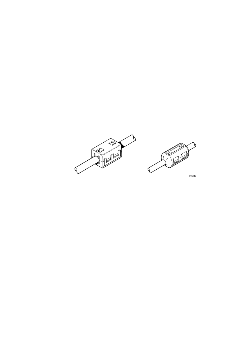
Suppression Ferrites
The following illustration shows typical cable suppression ferrites
used with Raymarine equipment. Always use the ferrites supplied
by Raymarine.
D3548-3
Figure 2-2: Typical Suppression Ferrites
Connections to Other Equipment
If your Raymarine equipment is to be connected to other equipment using a cable not supplied by Raymarine, a suppression ferrite must always be attached to the cable that is closest to the
Raymarine unit.
Page 24

2-4 DSM250 Digital Sounder Module
2.2 Unpacking and Inspecting the Components
Unpack your system carefully, to prevent damage to the equipment. Save the carton and packing, in case you need to return a
unit for service.
Check that you have all the correct system components. These
depend on your system package, as follows:
Table 2-1: Parts and Accessories
Item Part No. Supplied / Option
DSM250 Digital Sounder Module E62007 supplied
Handbook, DSM250
Handbook, Transducers for Fishfinders
Quick Reference Card, Fishfinder mode
Mounting screws, #8 (x4) N/A supplied
Power cable, 3 pin, 3 m R69053 supplied
2
hsb
cable assy
3 ft 3 in (1 m)
10 ft (3 m)
20 ft (6 m)
30 ft (10 m)
60 ft (20m)
2
hsb
In Line Terminator
2
hsb
Splitter Cable
Transducer and Cables (See
Transducers for Fishfinders Handbook
81196
81211
81196
86066
R55001
R55002
R55003
R55004
E55010
R58117
E55040
— —
)
2.3 Selecting the Equipment Location
Sounder Module Mounting Location
The DSM250 is waterproof to CFR46 is and designed to be
mounted either above or below deck. The unit should be protected
from physical damage and excessive vibration.
WARNING:
Mount the DSM250 in a protected area away from prolonged
exposure to rain, salt spray, and direct sunlight, but well
ventilated. Locate the sounder as close to the transducer as
possible. Raymarine suggests not locating the DSM250 on the
main console.
supplied
supplied
supplied
option
supplied
option
option
option
option
option
Page 25

Chapter 2: Installation 2-5
CAUTION:
Do not mount the DSM250 in the engine compartment.
When planning the installation, the following should be considered to ensure reliable and trouble free operation:
• Access: There must be sufficient space below the unit to enable
cable connections to the panel connectors, avoiding tight bends in
the cable.
• Interference: The selected location should be far enough away
from devices that may cause interference, such as motors, generators, and radio transmitter/receivers (see the EMC guidelines earlier in this section).
• Magnetic compass: Mount the unit at least 3 ft (1m) away from a
magnetic compass.
• Cable runs: The unit must be located near a DC power source.
The power cable supplied is 10 ft (3 m), but a longer cable can be
used if desired. Refer to Section 2.4.
The maximum length of cable between the sounder module and
the transducer unit should not normally exceed 30 ft (10 m). If
you need to use a longer cable, refer to Section 2.4.
• Environment: Good ventilation is required to prevent the unit
from overheating.
2.4 Cable Runs
Consider the following before installing the system cables:
• You will need to attach the power, transducer, and HSB cables.
• All cables should be adequately secured, protected from physical
• Sharp bends must be avoided.
CAUTION:
Removal of the transducer cable from the DSM250 while
power is turned on can cause sparks. As with any electronic
device, be sure the sounder module is mounted where it is well
ventilated and free from gasoline fumes.
Additional cables will be required if you are installing an integrated system.
damage, and protected from exposure to heat.
Avoid running cables through bilges or doorways, or close to
moving or hot objects.
Page 26

2-6 DSM250 Digital Sounder Module
• Where a cable passes through an exposed bulkhead or deckhead,
a watertight feed-through should be used.
• Secure cables in place using tie-wraps or lacing twine. Coil any
extra cable and tie it out of the way.
You will need to run the following cables:
• Power cable, supplied with the unit. This 10 ft (3 m) cable has a
connector plug at one end for connecting to the sounder module,
and 3 wires at the other end for connecting the power supply. The
power cable may be extended by up to 60 ft (20 m) using a wire
gauge of AWG 12 or greater. The DSM250 is intended for use
on ships’ DC power systems rated from 10.7 V to 32 V.
• HSB cable, supplied with the unit. This 10 ft (3m) cable is used to
connect the DSM250 to the display unit. Other lengths of HSB
cables are available from Raymarine. See Table 2-1 Parts and
Accessories on page 2-4.
• Transducer cab le, supplied with the transducer. This 30 ft (10 m)
cable has a connector plug (with an outer nut that you must attach)
at one end for the display unit or extension cable. The transducer
cable may be extended up to a maximum of 60 ft (20 m) using
optional extension cables. For details, see document number
81196, Transducers for Fishfinders Owner’s Handbook.
WARNING:
Do not cut the transducer cable or remove the connector.
Do not try to shorten or splice the cable. Cutting the
transducer cable will severely reduce sonar performance.
If the cable is cut, it must be replaced—it cannot be repaired.
Cutting the cable will also void the warranty.
Page 27
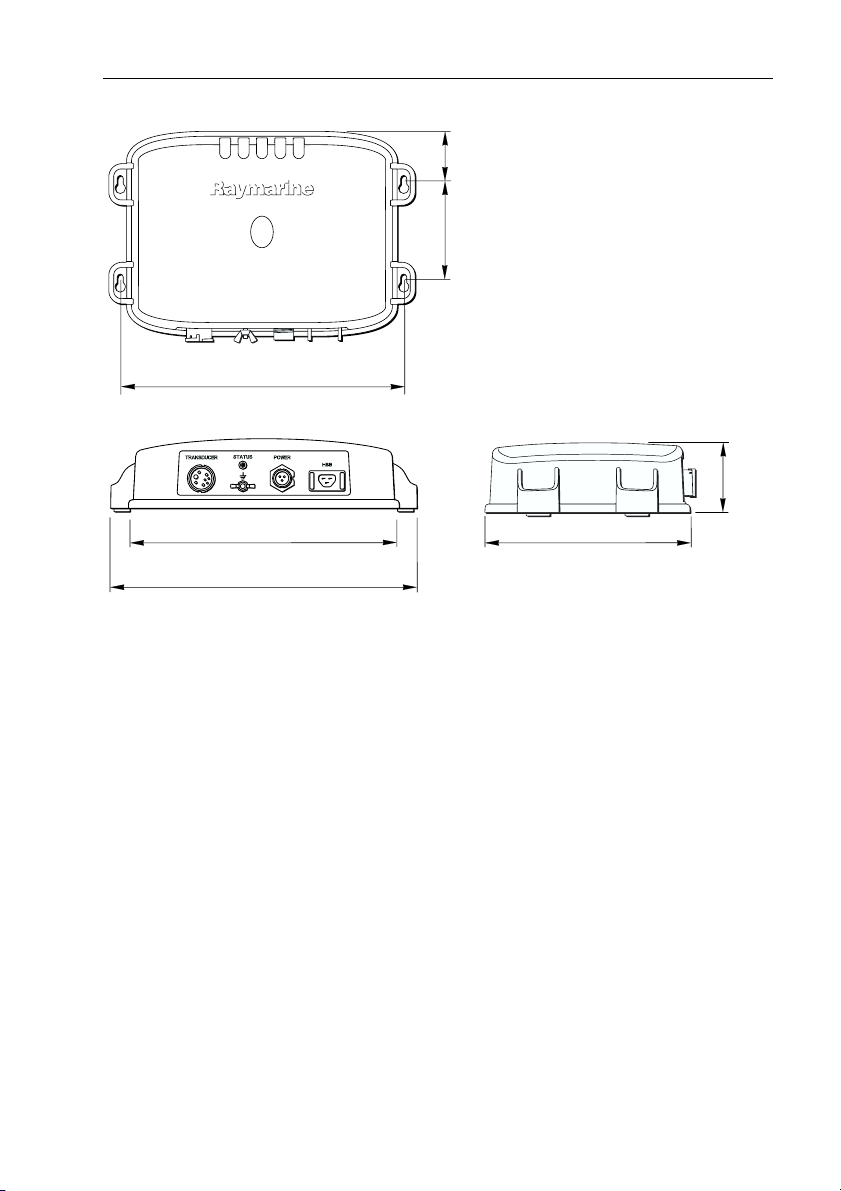
Chapter 2: Installation 2-7
1.65 in
(41.8 mm)
3.46 in
(88 mm)
Weight: 2.2 lbs (1.0 Kg)
9.96 in (252.9 mm)
9.51 in (241.6 mm)
10.76 in (273.3 mm)
Figure 2-3: DSM250 Unit Dimensions
Compass Safe Distance: 39 in (1 m)
D6168-1
7.37 in (187.2 mm)
2.43 in
(61.7 mm)
Page 28

2-8 DSM250 Digital Sounder Module
2.5 Mounting the Sounder Module
The DSM250 can be installed either above or below deck using
the supplied hardware.
CAUTION:
Do not mount the DSM250 in the engine compartment.
To allow for proper water drainage and ease of cable connection,
the DMS250 should be mounted vertically, so that the cables can
hang below the unit, as in Figure 2-4 .
To mount the DSM250:
1. Hold the module in the location where you want to mount it, making sure the unit is perpendicular to the floor, as in Figure 2-4 .
2. With a pencil, mark the tops (narrow ends) of the four key holes
onto the mounting surface. Set aside the module.
3. Drill a 9/64" pilot hole at each of the four marked locations.
Note: For fiberglass with a gelcoat surface, you should overdrill
the surface to prevent the gelcoat from chipping when driving in
the screw. Before drilling the pilot hole, hand drill the marked location with an oversized bit and countersink to approximately
3/8" diameter.
4. Drive the supplied #8 screws into the pilot holes. Screw them in
about half way.
5. Mount the module to the surface, slipping the screw heads
through the four key holes.
6. Press the module downward so the screws align with the narrow
end of the keyholes.
7. Tighten the screws. Do not overtighten.
Page 29
Chapter 2: Installation 2-9
D6183-1
Figure 2-4: Mounting the DSM250
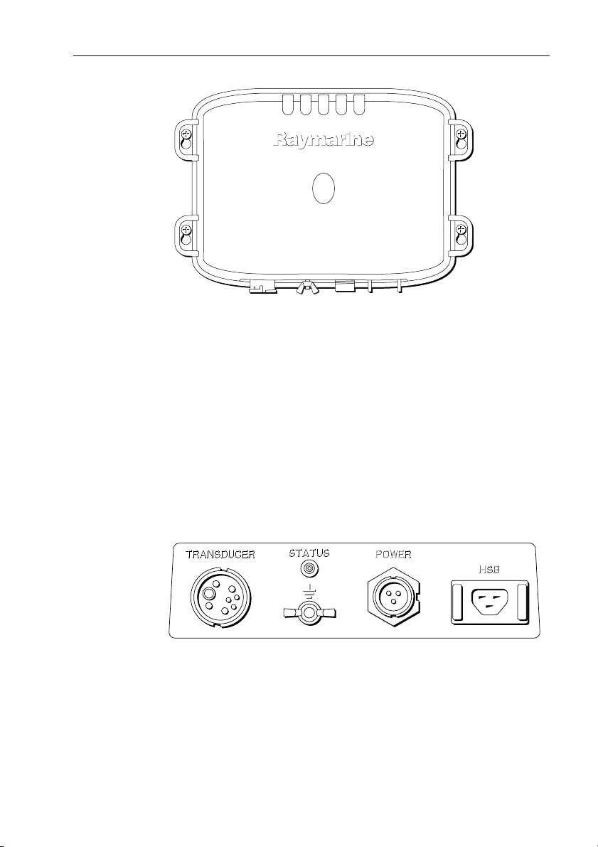
2.6 System Connections
The rear of the display unit provides the following connection
sockets:
• Transducer connection.
• Ground connection.
• Power, for 12 V, 24 V, or 32 V DC power connection and one RF
ground (screen) connection.
• HSB, in/out connector for connecting to an
play (Chartplotter, Fishfinder or Pathfinder Radar)
2
hsb
PLUS Series dis-
D6161-1
Figure 2-5: DSM250 Connector Panel
The following sections detail the connectors used when installing
the DSM250.
Page 30

2-10 DSM250 Digital Sounder Module
DC Power Connection
The DSM250 is intended for use on ships’ DC power systems
rated from 10.7 V to 32 V.
The power connection to the unit should be made at either the output of the battery isolator switch, or at a DC power distribution
panel. Raymarine recommends that power is fed directly to the
DSM250 via its own dedicated cable system and MUST be protected by a thermal circuit breaker or fuse on the red (positive)
wire, installed close to the power connection.
A 10 ft (3 m) power cable is supplied for connecting the ship’s DC
power to the unit. The power cable may be extended by up to 60 ft
(20 m) using a wire gauge of AWG 12 or greater.
DC power is connected at the three-pin POWER connector on the
unit’s connector panel. The connector (viewed from the outside)
and pin functions are shown in the following diagram and table.
f
1
2
3
D6162-1
Figure 2-6: Power Connector
Pin No. Function Color
1 Battery positive (12/24/32 V systems) Red
2 Battery negative Black
3 Shield (drain wire) No insulation
The RED wire must be connected to the feed from the positive (+)
battery terminal and the BLACK wire to the feed from the negative (–) battery terminal. The shield wire (drain) should be connected to the ship’s RF ground as described in Ground
Connection on page 2-11.
Install a quick blow 8 amp fuse on the red (positive) wire.
Page 31

Chapter 2: Installation 2-11
WARNING:
If the power connections are accidentally reversed th e system will
not work. Use a multimeter to ensure that the input power leads
are connected for correct polarity.
There is no power switch on the DSM250. The unit turns on when
the power cord is attached to ship’s power and plugged into the
POWER connector on the connector panel.
Note: You should locate the DSM250 so that the power cord can be
easily removed, if necessary. If the sounder is placed in a difficult-toreach location, Raymarine strongly suggests installing an on/off
switch on the DSM250 power cord at a point where it is easily accessible.
Ground Connection
It is important that an effective RF ground is connected to the system. A single ground point should be used for all equipment. You
may ground the DSM250 by connecting the drain wire (shield) of
the Power Input cable to the ship’s RF ground. If you need to
extend the wire, the extension wire should be an 8 mm braid or
AWG 10 multi-stranded cable.
If your vessel has a dedicated ground strap available, you may
alternatively attach it to the ground wing nut on the rear panel of
the module.
If your vessel does not have an RF system, connect the drain wire
to the negative battery terminal.
The DC system should be either:
• Negative grounded, with the negative battery terminal connected
to the ship’s ground.
• Floating, with neither battery terminal connected to the ship’s
ground.
WARNING:
This system is not intended for use on “positive” ground vessels.
The power cable Ground (earth) connections must be connected
to the ship’s ground as described above.
Page 32

2-12 DSM250 Digital Sounder Module
2
hsb
Connection
The DSM250 must be connected to an
2
hsb
PLUS Radar, Chartplotter, or Fishfinder display unit to show echo sounder data. The
DSM250 will not work with older HSB (non-PLUS) displays.
Note: Older HSB (non-PLUS) display units must be upgraded to
hsb
before they can function with the DSM250.
An HSB cable is required to connect the sounder module to the
display unit for showing echo sounder data. A 3m (10 ft) HSB
cable is supplied with the DSM250. These cables are also available
in lengths of 1, 6, 10, and 20 m. See Table 2-1 Parts and Accesso-
ries on page 2-4 for the complete list and associated part numbers.
The HSB cable is attached to the three-pin male connector marked
HSB on the connector panel of the sounder module. The connector
pins are shown in the following diagram; this is information is
provided as an aid to fault diagnosis.
HSB connector
HSB connector
Pin Pin name Function
1 CGND Screen
Pin 1
Pin 3
Pin 2
2 HSB_POS HSB
3 HSB_NEG HSB
2
Rear of Display Unit
1
2 3
HSB
D4253-4
Figure 2-7: HSB Connector
The HSB cables have ferrite clamps attached at each end to ensure
EMC conformance.
Page 33

Chapter 2: Installation 2-13
Transducer Connection
A 30 ft (10m) cable is supplied with the transducer. The transducer cable may be extended up to a maximum of 60 ft (20 m)
using optional extension cables. For details, see document number
81196, Transducers for Fishfinders Owner’s Handbook.
The transducer cable connector (and Y-shaped connector, if supplied) has a nut that has been removed to aid installation. To enable you to complete the installation without cutting the cable,
ensure that any holes you drill are large enough to accept the connector, with the nut removed (approximately 13/16" or 21 mm).
WARNING:
Take care not to pull on the cable. This can damage the
transducer wires.
Before attaching the transducer cable, you will need to attach the
connector nut and split ring. These items, plus a wedge tool, are
included in the transducer packaging.
The transducer cable is attached to the 7 pin male connector
marked
How you connect the cable depends on the type of transducer you
have installed:
TRANSDUCER on the connector panel of the DSM250.
• Combined depth/speed/temp transducers (‘triducers’) have a 7
pin female connector. Attach the transducer cable connector
directly to the display unit.
• Combined speed/temperature transducers have a 3 pin female
connector that requires the use of an additional Y-shaped cable
(Raymarine part number E66022) to attach to the 7 pin connector
on the display. This Y-cable is included with your speed/temperature transducer.
Attach the 7 pin female connector on the Y-cable to the sounder
module, and then attach the transducer cable to the 3 pin male
connector on the Y-cable.
• Depth-only transducers have a 7 pin female connector.
Attach the transducer cable connector directly to the sounder
module.
If being installed in conjunction with a speed/temperature transducer, attach the Y-cable’s 7 pin female connector to the sounder
module, and then attach the transducer cable to the 7 pin male
connector on the Y-cable.
Page 34

2-14 DSM250 Digital Sounder Module
Note: If your system requires both a Y-cable and a transducer extension cable, ensure that you connect the Y-cable to the sounder module
and the extension cable to the transducer.
The connector pins are shown in the following diagram, together
with the connections and wire colors; this is information is provided as an aid to fault diagnosis.
WARNING:
Do not cut the transducer cable or remove the connector.
Do not try to shorten or splice the cable. Cutting the transducer
cable will severely reduce sonar performance.
If the cable is cut, it must be replaced—it cannot be repaired.
Cutting the cable will also void the warranty.
5
2
1
4
3
7
6
D4850-2
Figure 2-8: DSM250 Transducer Connector
Pin
Function Color
No.
1 Speed Red 5 Speed/Temp Ground Brown
2 Tem p White 6 + Depth Blue
3 Shield Drain 7 - Depth Black
4 Sense Green
Pin
Function Color
No.
CAUTION:
Removing the transducer cable from the rear of the DSM250
while the sounder module is powered on can cause sparks. Only
remove the transducer cable after power has been removed from
the DSM250.
Page 35

Chapter 2: Installation 2-15
If the transducer cable is accidentally removed while the
DSM250 is powered on, remove power from the sounder module,
replace the transducer cable, and then return power to the
module. As a safety feature, the DSM250 only recognizes that the
transducer is connected at power-up.
EMC Conformance
Always check the installation before going to sea to make sure
that it is not affected by radio transmissions, engine starting, etc.
D6177-1
Figure 2-9: Properly Mounted Sounder Module
Page 36

2-16 DSM250 Digital Sounder Module
Page 37

Chapter 3: Getting Started 3-1
Chapter 3: Getting Started
3.1 Introduction
This chapter provides basic instructions to get you started using
the DSM250 Digital Sounder Module. It describes automatically
updating the display unit’s software to be compatible with the
DSM250, if necessary. It also describes Simulator mode and can
help you to become familiar with the basic functions of the display’s controls in Sonar operation mode. More detailed information on using the controls and operating in Sonar mode is
provided in Chapter 5 and Chapter 6, respectively.
Note: All se ttings described in this chapter are retained when the unit
is powered off. However, there is a one-minute delay from the time
you make the setting change to when the DSM250 places it in memory. If you power down the sounder less than one minute after making
a change, the setting is lost.
3.2 Powering on the Sounder Module
There is no power switch on the DSM250. The unit turns on when
the power cord is attached to ship’s power and plugged into the
POWER connector on the connector panel.
WARNING:
The DSM250 should be located so that the power cord can be
easily removed, if necessary. If the sounder is placed in a difficultto-reach location, Raymarine strongly suggests installing a
power switch on the DSM250 power cord at a point where it is
easily accessible.
Status LED
The LED on the front panel blinks green when the module is powered on and operating normally. If the unit detects a problem, the
LED blinks amber to indicate a warning or red for an error. The
number of times the LED blinks is a code representing the nature
of the problem. See Status LED on page 7-6 for more details.
Page 38

3-2 DSM250 Digital Sounder Module
3.3 Updating Software on the Display Unit
Before it can show sonar data received from the DSM250, the display unit must be running a software version that recognizes the
sounder module on the
gram routine that automatically polls the software version running
on the display unit and if necessary, updates it (via
compatible with the DSM250.
➤ To automatically check and update the display unit software version:
1. Ensure both the DSM250 and display unit are powered off.
2. Ensure the HSB cable is properly connected between the units.
3. Disconnect the transducer cable from the DSM250. (This is
essential.)
4. Power on the DSM250.
5. Within 30 seconds of powering on the DSM250, power on the dis-
play unit.
If running an older version, the display software is updated and the
unit beeps. When the software update is complete (or if no update
is required), the normal startup screen appears on the display.
6. Power off the DSM250 and reconnect the transducer.
7. Power on the DSM250.
2
hsb
network. The DSM250 contains a pro-
2
hsb
) to be
3.4 Selecting Repeater Mode
Depth data that is to be shared over the
from the device that has been designated as the master sonar unit.
Only a DSM250 or an
ter unit. For the DSM250 master to repeat its sonar image data to
a display unit, the display must be designated as the REPEATER.
When using the DSM250 with a PLUS radar or chartplotter display, this is not an issue—the DSM250 is automatically set as the
master and the display unit the repeater. However, the DSM250
can also repeat its image data on a fishfinder display. In this case,
both units are capable of collecting sonar data so you must tell the
display it is to be a repeater for the DSM250 and not a master unit
on its own.
If your DSM250 is repeating its sonar data over a PLUS radar or
chartplotter display, the proper settings are made automatically.
You need do nothing else.
hsb
2
hsb
network is sourced
2
PLUS fishfinder display can be a mas-
Page 39

Chapter 3: Getting Started 3-3
However, if your repeater display is a PLUS fishfinder, you must
tell the unit to be a repeater.
➤ To set the fishfinder display to be the sonar repeater:
MENU
SONAR
SET UP¬
1. Press the MENU key.
The Menu soft keys appear.
2. Press the SONAR SET UP soft key.
The Sonar Set Up menu appears.
3. Press the trackpad until the SONAR HSB MODE parameter is high-
lighted (selected).
4. Press the REPEATER soft key.
5. Press ENTER.
The display unit is now designated as the Repeater.
Full details on setting up your DSM250 and display are given in
Chapter 4.
3.5 Selecting Sonar Mode
If properly connected to an
Fishfinder display unit, you can begin viewing echo sounder data
by setting the display to Sonar mode.
2
hsb
PLUS Radar, Chartplotter, or
DISPLAY
Note: Data, such as depth, speed, temperature, log, and trip are still
available even if Sonar mode is not selected.
➤ To set the mode, press the DISPLAY key to show the DISPLAY pop-up,
then press again to cycle through the modes available, shown in
Figure 3-1 .
Page 40

3-4 DSM250 Digital Sounder Module
"DISPLAY" TO SELECT FULL SCREEN OPTION
SOFTKEYS TO SELECT WINDOW OPTION
CURSOR
BRG
RNG
o
099
2.410
R
nm
0
0
RADAR
WINDOWS
OFF ON
CHART SONAR LOG
ft
SELECT
WINDOWS
HOR VER
60
SPLIT
D6191-1
Figure 3-1: Using the DISPLAY Key
The selected mode is shown by an icon with a black (monochrome display) or red (color LCD) border and the mode is displayed on the screen.
When SONAR mode is shown (as in Figure 3-1 ), press ENTER or
CLEAR. The default soft keys are displayed. The display shows
the sounder screen.
Page 41

Chapter 3: Getting Started 3-5
AUTO G RZ
50kHz
0
20
40
Figure 3-2: Typical Sonar Mode Display
3.6 Simulator Mode
The DSM250 includes a simulator function that enables you to
practice operating in Sonar Mode without data from the transducer. The sounder must be connected to an
Chartplotter, or Fishfinder display unit to show echo sounder data.
The DSM250 will not work with older HSB (non-PLUS) displays.
Note: Older HSB (non-PLUS) display units must be upgraded to
before they can function with the DSM250.
Before using Simulator mode, make sure the HSB cable is connected from the DSM250 to the display unit and that both the
DSM250 and display unit are connected to ship’s power.
If you have not fully installed the sonar module, you can still operate
in Simulator mode by connecting the module and display devices
via the HSB cable. Then connect the DSM250 and the display unit
to a 12V or 24V DC power supply, attaching the red wire from the
power lead to positive (+) and the black wire to negative (-).
ft
ZOOMFREQUENCY
BTM.LOCK A-SCOPE
60
D6180-1
hsb
2
PLUS Radar,
hsb
2
Page 42

3-6 DSM250 Digital Sounder Module
Figure 3-3 demonstrates how to setup the DSM250 for Simulator
mode; Chapter 2 gives full installation details.
Digital Sounder Module
2
hsb
PLUS Display Unit
2
hsb
Figure 3-3: Simulator Mode Setup
Viewing Simulator Data
After you have properly connected and powered up the DSM250
and display units, you can toggle Simulator mode on and off using
the Sonar Setup menu.
➤ To view simulated sounder images:
MENU
SONAR
SET UP¬
1. Press the MENU key on display unit.
The Setup soft keys appear.
2. Press the SONAR SET UP soft key.
The Sonar setup menu pop-up is displayed.
3. Use the trackpad to move the selection bar over the option
SONAR SIMULATOR. The simulator soft keys are displayed.
4. Press the ON soft key to switch on the sonar simulator.
5. Press ENTER twice to return to the default display.
When simulator mode is on a simulator dialog box is displayed.
RF Ground
Red
Black
DC Volts
D6197-1
When the display is switched off then on again, simulator mode is
maintained. It is recommended that you select the System Set Up
Menu and switch off simulator mode when you have finished.
Note: Any waypoints placed on the chartplotter in simulator mode
are retained in the database list and are available for use in routes.
Page 43

Chapter 4: System Setup 4-1
Chapter 4: System Setup
4.1 Introduction
Once you have installed your DSM250 and are familiar with its
basic operation (described in Chapter 2 and Chapter 3), you need
to set it up so that it displays information according to your preferences.
MENU
This is achieved using the soft key controls that are displayed
when you press the ME
In most cases, you will only need to use the MENU key options
when you first set up your system. As you become more familiar
with your system, you may decide to customize some aspects,
such as the screen and help setting.
Note: All se ttings described in this chapter are retained when the unit
is powered off. However, there is a one-minute delay from the time
you make the setting change to when the DSM250 places it in memory. If you power down the sounder less than one minute after making
a change, the setting is lost.
This chapter covers the following topics:
• Changing the default set up parameters
• Sounder specific parameter functions and default settings
You should check the functions of the parameters and decide on
the new settings before making the changes.
NU key.
4.2 Changing the Set Up Parameters
The set up parameters are divided into two sections:
• System, to control the aspects of the system that are not specific to
the sounder module.
• Sonar, to control the Sonar-mode display preferences, including
HSB mode, calibration, and simulator.
This section provides instructions for displaying and changing the
default values. The following sections list the parameters and
their possible settings and describe the function of each parameter
in turn.
Page 44

4-2 DSM250 Digital Sounder Module
➤ To change settings:
1. Press the MENU key in Sonar mode to display the set up soft keys.
SYSTEM
SET UP¬
SONAR
SET UP¬
SCROLL
SPEED
TRIP
RESET
D5019-1
2. Press the soft key for the set up you desire.
The requested set up menu is displayed, listing the parameters
and their current settings.
3. Use the trackpad to move the selection bar up and down the list.
An arrow is displayed at the top or bottom right-hand corner if you
can scroll the list to display further parameters.
As each line is highlighted, the soft keys are updated to show the
settings available.
• For parameters that have a numeric value, or more than four
possible settings, a scroll list is displayed above two of the soft
keys.
• Some parameters are controlled by a slider that is displayed
above two of the soft keys.
• For some parameters, a soft key provides access to a submenu of further options.
4. Press the soft key corresponding to the desired setting or, for
scroll lists, use the soft keys to scroll forwards or backwards
through the list until the desired setting is displayed. This setting
is retained when you move the selection bar on to the next parameter in the menu list.
For sliders, press the appropriate soft key repeatedly to increase
or decrease the slider value in individual steps, or press and hold
the key to change the setting quickly.
5. Once you have set all the desired values, press ENTER to clear the
menu and return to the set up soft keys.
6. Press ENTER, MENU, or CLEAR to clear the soft keys and return
to the default display.
Page 45

Chapter 4: System Setup 4-3
4.3 System Set Up Parameters
SYSTEM
SET UP¬
The SYSTEM SET UP option enables you to set up your system configuration and personal preferences.
The following table lists the System menus and their options,
shows the factory default setting, and provides a space for you to
make a note of your new setting. Each parameter is described in
the following subsections.
Table 4-1: System Set Up Parameters
Menu Options
DATA BOXES
POSITION
SPEED
DEPTH
COG
SOG
TIME
DATE
WIND
WAYPOINT
CROSS TRACK ERROR
HEADING
LOG/TRIP
PILOT
VMG
TEMPERATURE
TIDE SET/DRIFT
BEARING MODE MAGNETIC OR TRUE TRUE
OFF, LAT/LONG, or TDs
OFF or ON
OFF or ON
OFF or ON
OFF or ON
OFF or ON
OFF or ON
OFF, APPARENT, TRUE, BOTH
OFF, LAT/LON, RNG/BRG/TTG
OFF or ON
OFF or ON
OFF or ON
OFF or ON
OFF, WIND, WPT, or BOTH
OFF or ON
OFF or ON
Factory
Default
OFF
OFF
OFF
OFF
OFF
OFF
OFF
OFF
OFF
OFF
OFF
OFF
OFF
OFF
OFF
OFF
New
Setting
CURSOR REFERENCE MAG/TRUE or RELATIVE RELATIVE
CURSOR READOUT OFF, LAT/LONG, RNG/BRG, or
BOTH
DAY/NIGHT DAY/NIGHT DAY
HELP OFF or ON ON
SOFT KEYS OFF or ON ON
KEY BEEP OFF or ON ON
MOB DATA DR or POSITION DR
PILOT POP-UP OFF or ON OFF
RNG/BRG
Page 46

4-4 DSM250 Digital Sounder Module
Table 4-1: System Set Up Parameters
Menu Options
MENU TIMEOUT PERIOD NO TIMEOUT, 10, 20, or
DISTANCE UNITS NAUTICAL MILES, STATUTE
SPEED UNITS KNOTS, MILES PER HOUR, or
DEPTH UNITS METERS, FEET, OR FATHOMS FEET
TEMPERATURE UNITS CENTIGRADE or FAHRENHEIT FAHRENHEIT
VARIATIO N SOURCE AUTOMATIC or MANUAL AUTOMATIC
BRIDGE NMEA HEADING OFF or ON OFF
NMEA-OUT SET UP
APB
BWC
BWR
DBT
DPT
MTW
RMB
RSD
RTE
TTM
VHW
VLW
WPL
GGA
GLL
RMA
RMC
VTG
ZDA
30 SECONDS
MILES, KILOMETERS, or
KILOYARDS
KM PER HOUR
OFF or ON
OFF or ON
OFF or ON
OFF or ON
OFF or ON
OFF or ON
OFF or ON
OFF or ON
OFF or ON
OFF or ON
OFF or ON
OFF or ON
OFF or ON
OFF or ON
OFF or ON
OFF or ON
OFF or ON
OFF or ON
OFF or ON
Factory
Default
NO TIMEOUT
NAUTICAL miles
KNOTS
ON
ON
ON
ON
ON
ON
ON
ON
ON
ON
ON
ON
ON
ON
ON
ON
ON
ON
ON
New
Setting
CURSOR ECHO
RADAR CURSOR IN
CHART CURSOR IN
SEATALK CURSOR OUT
CURSOR ECHO LOCAL
DATE FORMAT DD/MM/YY or MM/DD/YY MM/DD/YY
TIME FORMAT 12 HO UR o r 24 HO UR 12 HOUR
OFF or ON
OFF or ON
OFF or ON
OFF or ON
OFF
OFF
OFF
ON
Page 47

Chapter 4: System Setup 4-5
Table 4-1: System Set Up Parameters
Menu Options
TIME OFFSET UTC, or local offset value:
GPS SOG/COG FILTER HIGH, MEDIUM, or LOW
COMPASS SET UP LINEARISE COMPASS or
LANGUAGE English (UK), English (US),
SIMULATOR OFF, DATA, RADAR or BOTH OFF
Plus or minus up to 12 hours, in
whole hours
ALIGN HEADING
Danish, French, Germ an,
Dutch, Icelandic, Italian, Norwegian, Portuguese, Spanish,
Swedish, or Finnish
Data Boxes
Press the SELECT BOXES soft key to display the data box sub-menu.
This enables you to select up to 6 data boxes that you can display
on the sounder.
Note:
1. A fixed set of sixteen (nine in the monochrome displays) of these
data items are available for display in the Nav Data half-screen
window (see Chapter 3).
2. In addition to these grouped data boxes, boxes for the cursor
readout, VRM/EBL data, waypoint data, MOB data and simulator status are displayed when selected or when the appropriate
function is active.
3. Radar data is available only if the display is a PLUS Series radar
display or is connected to one via
hsb
Factory
Default
UTC
English (US)
2
.
New
Setting
Data boxes provide regularly used data in a compact form so that
most of the graphics can still be seen. The ones you select here
can be turned on and off as a group during normal operation, and
you can also move them around the screen individually using the
context-sensitive cursor. Refer to Viewing Data Boxes on page 5-
14.
Page 48

4-6 DSM250 Digital Sounder Module
Bearing Mode
The mode (magnetic or true) of all the bearing and heading data
displayed. This is indicated in the radar status bar after the heading value, if displayed.
Cursor Reference
The mode of the bearing data displayed for the cursor readout.
The bearing information can be displayed in either of two forms:
• Relative: The bearing relative to your vessel’s heading.
• Mag/True: The actual bearing in either degrees magnetic or
degrees true. This option is only available in Radar mode if your
system includes a radar display and you have heading data from a
compass.
If you choose this mode, the selection you made for the previous
parameter (Bearing Mode), °M or °T, is displayed in the cursor
(Rng/Brg) data boxes. The current units are shown for the heading
value in the status bar at the top of the screen.
Cursor Readout
This option controls whether radar cursor data is shown in latitude
and longitude or in range and bearing. Alternatively, you can
show both types of readout, in separate boxes, or turn the cursor
data box off.
You can also turn the cursor readout box(es) on and off during
normal operation, via the SCREEN default soft key.
Day/Night
This option enables you to change the display between day and
night modes.
On a color LCD, NIGHT mode uses a different color palette, more
suited to night time viewing. The default setting is DAY.
For monochrome displays, the normal DAY presentation displays
black targets on a white background. If you select NIGHT, the pic-
ture is reversed, so that white targets are shown on a black background to reduce the intensity of the image.
Page 49

Chapter 4: System Setup 4-7
Help
When Help is set to ON, a prompt appears when selecting a soft
key or menu choice and when using the context-sensitive cursor.
The help message is cleared when an action is selected.
Soft Keys
When the Soft Keys option is set to ON, the default soft keys are
displayed if no other operation is in progress.
When the Soft Keys option is set to OFF, the default soft keys are
only displayed when a soft key is pressed. They also disappear if
no operation is performed for 10 seconds.
Key Beep
This option controls whether or not the keys sound a tone when
you press them.
MOB Data
This option controls whether MOB data is based on position data,
or on dead reckoning (DR). Dead reckoning normally provides a
better indication of the course to an object in the water, on the
assumption that your vessel and the object are both subject to the
same tide and wind effects.
Autopilot Pop Up
This option controls whether or not the autopilot pop up is displayed. When set to ON, when the status and locked heading of the
autopilot changes, they are displayed in a pop up box. The box is
removed from the display after two seconds.
When Autopilot Pop set to OFF, the pop up box is disabled.
Menu Timeout Period
With no timeout set, menus and soft key labels remain displayed
until you clear them by pressing ENTER, CLEAR or the appropriate dedicated key.
If you set a value here, the menus and soft key labels are cleared if
a key has not been pressed for the specified number of seconds.
Page 50

4-8 DSM250 Digital Sounder Module
This setting does not affect the default soft key labels, which are
controlled by the Soft Keys option (see above).
Units
You can set the units for speed, depth, and temperature. The units
you set will be used to display all data, including information
received from other instruments on the system. However, the distance units do not affect the instrumented range of the radar,
which is always in nautical miles.
Note: The ‘Units’ values set here are also used in the other display
modes.
Variation Source
The variation value is the difference between True and Magnetic
direction data for heading or bearing values. The Variation Source
option provides soft keys for selecting Auto or Manual variation
mode, displays the current variation value for each and highlights
the currently selected mode.
Auto Mode
If you select Auto mode, the unit obtains the value of variation
automatically, normally from received data. The variation value
that is used depends on the data available and is selected in the
following order of priority:
1. Variation value from the same source as the heading data:
• If heading data is being taken from NMEA, then variation is
also taken from NMEA
• If heading is taken from SeaTalk, then SeaTalk variation is
used
2. Variation value from a different source:
• If heading data is being taken from NMEA, but no NMEA
variation is available, then variation is taken from SeaTalk
• If heading is taken from SeaTalk, but no SeaTalk variation is
available, then variation is taken from NMEA
3. A calculated variation value, using position data, if no SeaTalk or
NMEA value is available
4. The current manual variation value, if no SeaTalk or NMEA
value and no position data is available
Page 51

Chapter 4: System Setup 4-9
Manual Mode
If you select Manual mode, by pressing either of the MANUAL
keys, you can specify the local variation value according to the
area in which you are operating.
Press the appropriate MANUAL key to adjust the variation up or
down, to a maximum of 30° East or West.
This value is then transmitted to any other SeaTalk instruments on
your system. It is retained if you turn the display off and on again.
In Manual mode, incoming NMEA variation is ignored. However,
if the variation is changed on another SeaTalk instrument, the new
value is used and the manual value that is displayed is updated.
Note: The Manual variation value defaults to 0°, so it is important to
set up a value if variation is not available from an external source.
Bridge NMEA Heading
The display unit sends NMEA input data to the SeaTalk bus. The
Bridge NMEA Heading option can be used to prevent NMEA
heading data being bridged onto the SeaTalk bus.
For example, if you have a course computer connected on SeaTalk
and NMEA, and an active compass connected on NMEA (for
MARPA), SeaTalk data overrides NMEA data in the course computer.
You should therefore switch OFF the Bridge NMEA Heading
option to ensure the course computer receives the same NMEA
heading input as the rest of the system.
NMEA-Out Set Up
This option lets you disable the transmission of specific NMEA
sentences, which may be necessary if you have other instruments
sending the same data as your sounder.
For example, if the DPT (depth) sentence is set ON but the
sounder’s transducer is designed to sense temperature and speed
only, the depth value will be transmitted as zero. If you also have
an ST60 Depth instrument installed, there may be confusion
between the zero depth sent by the sounder and the actual depth
sent by the ST60. Turning OFF the DPT sentence disables the read-
ing from the sounder.
Page 52

4-10 DSM250 Digital Sounder Module
The factory default for all NMEA sentences is transmission ON.
Disable the sentence by selecting the OFF soft key.
The following table displays the available NMEA sentences and
their meanings.
Table 4-2: NMEA Sentences
Sentence Meaning
APB Autopilot Sentence “B”
BWC Bearing & Distance to Waypoint
BWR Bearing & Distance to Waypoint – Rhumb Line
DBT Depth Below Transducer (see note below)
DPT Depth (see note below)
MTW Water Temperature
RMB Recommended Minimum Navigation Information
RSD Radar System Data
RTE Routes
TTM Trac ked Targe t M ess age
VHW Water Speed and Heading
VLW Distance Travelled through the Water
WPL Waypoint Location
GGA Global Positioning System Fix Data
GLL Geographic Position – Latitude/Longitude
RMA Recommended Minimum Specific Loran-C Data
RMC Recommended Minimum Specific GPS/TRANSIT Data
VTG Course Over Ground and Ground Speed
ZDA Time and D ate
The changes do not take effect until after ENTER is pressed. Consult your NMEA instrumentation documentation to determine
which strings should remain ON.
Page 53

Chapter 4: System Setup 4-11
Note: The DSM250 outputs the same depth value for DBT and DPT,
regardless of the Depth Offset value in Sonar Setup.
Cursor Echo
You can set up an integrated system so that radar and chartplotter
displays connected via SeaTalk can display each other’s cursors.
Cursor echo functions so that you can display a chart cursor on the
radar picture, or a radar cursor on the chart picture (you cannot
display a remote radar cursor in a radar window nor can you display a remote chart cursor in a chart window). When the appropriate options are switched on, each display shows its own cursor,
plus the cursor of the other display with appropriate cursor text
(RDR or CHRT) to indicate its origin. This means that you could
move the cursor over a target on the radar display and check the
identity of the target by looking at the radar cursor position on the
chartplotter.
Press the CURSOR ECHO soft key to display the cursor transfer soft
keys. The following options can be toggled ON or OFF:
• Radar Cursor In: displays the cursor from another radar on the
chart display or chart window (default - OFF).
• Chart Cursor In: displays the cursor from another or chartplot-
ter on the radar display or radar window (default - OFF).
Note: The remote display must have SeaTalk Cursor Out enabled.
• SeaTalk Cursor Out: enables the output, onto SeaTalk, of the
display’s own cursor (default - OFF).
• Cursor Echo Local: echoes the cursor position between open
windows on the same display (default - ON).
If you set the options to OFF, no cursor echo information is displayed.
Date and Time Settings
Set your preferred date format (DD/MM/YY or MM/DD/YY) and
time format (12 or 24 hour). If you wish to display local time, use
the soft keys to change from UTC to the desired time offset. This
can be up to plus or minus 12 hours, in hourly steps.
Page 54

4-12 DSM250 Digital Sounder Module
GPS SOG/COG Filter
The SOG/COG filter averages the velocity vectors to compensate
for the oscillating motion of the vessel, giving a clearer indication
of the vessel’s course and speed. The filter does not affect the calculation of the GPS position. The velocity vectors calculated from
the GPS Signal give an instantaneous measure of speed and direction of the GPS antenna. The COG and SOG can therefore seem
erratic under certain conditions. For example, when a vessel is
moving slowly through rough seas, the antenna moves from side
to side as well as in the direction of the vessel.
Slow moving vessels, or vessels sailing in rough seas will benefit
from a high setting, whereas a power boat that can quickly change
speed and direction will benefit from a low setting.
Select the SOG/COG filter setting as required. This can be set to
HIGH, MEDIUM or LOW.
Compass Set Up
This option is used to calibrate a Raymarine heading sensor such
as the Pathfinder Smart Heading System. Controls are provided
for LINEARISE COMPASS, which detects and corrects for heading
errors caused by metal objects, and ALIGN HEADING, which
matches the displayed heading to a known heading or transit.
Refer to the Handbook supplied with your heading sensor for
more details.
Language
Select the language in which you wish information to be displayed. The selected language will be used for screen text, labels,
menus, and options, but will not affect the letters displayed by the
context-sensitive cursor. The language setting also affects the display format for lat/long position information.
Simulator
The simulator enables you to operate your display without data
from the transducer and/or external data sources. The system set
up simulator options have the following functions:
• Data provides simulated numerical data, and a waypoint display.
Page 55

Chapter 4: System Setup 4-13
• Radar provides simulated radar picture, with example targets.
The picture does not change if you change the range, although
the range rings are adjusted (see radar documentation).
• Both provides simulated data and radar picture.
When the simulator is switched on, a SIMULATOR data box is dis-
played during operation, showing the simulation selected.
Sonar simulator mode is set in the Sonar setup menu, described in
Section 4.4.
4.4 Sonar Set Up Parameters
SONAR
SET UP¬
The SONAR SET UP option enables you to set up the sounder
according to your system configuration and your personal preferences.
The following table lists the Sonar Set Up parameters and their
options, shows the factory default setting, and provides a space
for you to make a note of your new setting. Each parameter is
described in the following subsections.
Table 4-3: Sonar Mode Set Up Parameters
Parameter Options
TARGET DEPTH ID OFF
ON
COLOR BAR OFF
ON
DEPTH DIGIT SIZE LARGE
SMALL
SONAR HSB MODE REPEATER
MASTER
DEPTH OFFSET Value 0.0
SPEED CALIBRATE 0% to 200% 100%
TEMP CALIBRATE -9.0 °F to +9.0 °F 0°F
Factory
Default New Setting
OFF
ON
LARGE
MASTER
SONAR HISTORY LARGE or SMALL LARGE
SONAR INT REJ AUTO, L OW or HIGH AUTO
SONAR SIMULATOR OFF
ON
OFF
Page 56

4-14 DSM250 Digital Sounder Module
Target Depth ID
You can select whether the depth is shown for sonar echoes displayed on the screen. When Target Depth ID is set to ON, the
depth is displayed just above each fish echo. When set to OFF, the
depth of each echo is not displayed.
Color Bar
The color bar indicates the range of echoes displayed in each
color (shade of gray for monochrome displays). When set to ON
the color bar is displayed on the right hand side of the display.
Depth Digit Size
The depth under the boat is displayed in the bottom left hand corner of the display. You can select small or large digits for the
depth display.
Sonar HSB Mode
Note: This parameter only pertains when the display to which you
are outputting DSM250 image data is a PLUS fishfinder. If your display is a PLUS radar or chartplotter display, the REPEATER setting
is automatically selected and cannot be changed.
The Sonar HSB Mode setting designates whether the display
showing sounder data is the MASTER unit from which depth data is
to be sourced or a REPEATER of sonar data received from a master
unit. Only one unit should be designated the master at a time.
Note: Ensure that there is only one sonar master unit on the
work. Having more than one master unit will cause unpredictable results.
A sonar MASTER unit is connected directly to the transducer. Only
a DSM250 or a PLUS fishfinder display can be designated as the
master. A REPEATER display is connected via
unit so it can display sonar data the master has collected. A
REPEATER can be a radar, chartplotter or fishfinder display.
Because the DSM250 does not have a display of its own, the
DSM250 is always designated as the MASTER. Therefore, all dis-
play units showing sonar data from the DSM250 must be designated as a REPEATER.
2
hsb
to the master
hsb
2
net-
Page 57

Chapter 4: System Setup 4-15
This is not an issue when showing DSM250 data on a radar or
chart display because these units can never be a sonar master. In
this case, the DSM250 is automatically set as the master and the
display unit as the repeater. In fact, the MASTER selection is grayed
out when the sounder module is connected to a PLUS radar or chart
display.
However, if the display unit is a PLUS fishfinder, you are given a
choice. You must set the fishfinder display to REPEATER so that
there is no conflict on the
2
hsb
network (the DSM250 is always
designated as a master). You would only select MASTER when you
want to control the PLUS fishfinder display rather than the
DSM250. In this case, the fishfinder display unit must have its
own transducer connected and the DSM250 must be powered off
or have its HSB cable disconnected (thus removing it from the
2
hsb
network).
Note: If you switch the PLUS fishfinder display from REPEATER to
MASTER, you must remove the DSM250 from the
2
hsb
network and
power off & on the display unit for the changes to take effect.
Summary
1. When the display is a PLUS radar or chart unit, you can ignore
this parameter; the REPEATER setting is made for you automatically.
2. When the display is a PLUS fishfinder and you are using the
DSM250, select REPEATER.
3. When the display is a PLUS fishfinder and you want the display to
show its own sonar data rather than that of the DSM250, select
MASTER. In this scenario, the DSM250 must be powered off or be
physically removed from the
hsb
2
network.
Depth Offset
The depth offset is added to the measured depth value before it is
displayed. You can specify the depth as a positive value (WATER-
LINE OFFSET) or a negative value (KEEL OFFSET). The depth offset
can be set adjusted in 0.1 increments of the units you have
assigned for Depth Units in the setup parameters of the display
unit: meters, fathoms, or feet.
Page 58

4-16 DSM250 Digital Sounder Module
Speed Calibrate
If the transducer is equipped with a speed paddle wheel, the
DSM250 calculates the speed of the boat through the water. The
speed calibrate option enables you to adjust the displayed speed
so that it matches your actual speed through the water. You can
adjust the displayed speed from 1% to 200%.
If the sounder reading is too low, set Speed Calibration to more
than 100%. If the sounder reading is too high, set Speed Calibration to less than 100%.
Temperature Calibrate
If the transducer is equipped with a thermistor, the DSM250 calculates the temperature of the water. The temperature calibrate
option enables you to adjust the displayed temperature. You can
adjust the displayed temperature by -9.0°F to +9.0°F.
Sonar History
Sonar History determines the number of data sample columns that
appear on the screen at one time. The options are: SMALL, which
displays 240 columns of data or LARGE, which shows 480 columns.
Information displayed in a single column using the LARGE setting
would occupy two columns with SMALL. As a result, twice as
much data history is displayed under the LARGE setting. Data displayed using SMALL appears wider and scrolls across the screen
faster.
Sonar Interference Rejection
Two or more sonar-equipped vessels operating within range of
each other can create interference on the sounder screen. This
usually appears as vertical streaks in the water that do not represent actual targets.
The DSM250 includes a SONAR INT REJ option that can reduce
such interference, either manually or automatically. LOW rejects
only a small amount of the extraneous objects. Use this setting
when you want to be sure that what has been removed are really
false returns.
Page 59

Chapter 4: System Setup 4-17
HIGH cleans up much more interference but can degrade the
appearance of actual targets. AUTOMATIC selects the best rejection
level for you.
The default setting is AUTOMATIC.
Sonar Simulator
The simulator enables you to operate your display without data
from the transducer, in order to become familiar with the sounder
features and functions.
All controls are functional in Simulator mode with the exception
of STC.
Version/Serial Numbers
The area at the bottom of the Sonar Setup screen gives version
information for the system.
This area is informational only; it is not editable.
DISPLAY SW VERSION displays the software version of the display
unit.
MASTER SW VERSION displays the software version and product type
of the master unit, which under most circumstances would be the
DSM250.
MASTER S/N displays the serial number of the master unit, which
under normal circumstances would be the DSM250.
Page 60

4-18 DSM250 Digital Sounder Module
Page 61

Chapter 5: Basic Display Controls 5-1
Chapter 5: Basic Display Controls
5.1 Introduction
This chapter will help you to become familiar with the functions
of the display’s controls in Sonar mode. More detailed information on operating Sonar display mode is provided in Chapter 6.
Note: All se ttings described in this chapter are retained when the unit
is powered off. However, there is a one-minute delay from the time
you make the setting change to when the DSM250 places it in memory. If you power down the sounder less than one minute after making
a change, the setting is lost.
Simulator
The DSM250 includes a simulator function that enables you to
practice operating display controls in Sonar Mode without data
from the transducer. Section 3.6 describes how to switch the display to simulator mode.
The DSM250 must be connected to an
plotter, or Fishfinder display unit to show echo sounder data. The
DSM250 will not work with older HSB (non-PLUS) displays.
Note: Older HSB (non-PLUS) display units must be upgraded to
before they can function with the DSM250.
2
hsb
PLUS Radar, Chart-
hsb
2
5.2 Setting Color and Brightness
Brightness settings depend on the type of display you have. Monochrome displays offer lighting and contrast settings, while color
displays have brightness and color settings.
Lighting and Contrast (Monochrome Displays)
You can change the level of backlighting and contrast for the
screen and keys. The key lighting is set the same as the screen
lighting, except that it remains switched on at its lowest level even
when the screen lighting is turned off, so that you can always find
the keys.
Page 62

5-2 DSM250 Digital Sounder Module
➤ To change the lighting and contrast:
1. Press the MULTI key (or the MULTI knob on CRT radar units) to
display the soft key controls:
The last-used soft key is highlighted in inverse video (white text
on a black background).
37%70%
POWER
AUTO LO HI
LIGHT CONTRAST
WHT LINE
OFF ON
2. Press the LIGHT soft key if it is not already highlighted.
3. The LIGHT soft key toggles lighting ON/OFF.
4. Use the trackpad (up or down) to increase or decrease the setting.
You can press and hold the trackpad to change the setting more
rapidly. The lighting level is adjusted as you change the setting.
5. Press the CONTRAST soft key. Adjust the setting in the same way as
for the lighting. There are 64 different contrast levels.
50%
6. Press ENTER to return to the default screen, with the new lighting
and contrast levels retained, or press CLEAR to discard the
CONTRAST
changes and return to the default screen.
If lights are left ON when you switch off the display, the next time
the display is switched on, the lights will be ON, but at the default
setting of 42%. The new contrast level is retained until you reset
it, unless you set the control very low or very high; in this case,
the contrast will be restored as follows:
Contrast set < 30%restored to 30%
Contrast set > 70%restored to 70%
Brightness and Color Settings (Color Displays)
D4895-2
The MULTI key on a color LCD unit provides controls to set up
the display colors and brightness. You can choose the background
color and the color threshold; color threshold lets you determine
which echoes are displayed, by selecting the minimum color
strength the sounder uses.
Page 63

Chapter 5: Basic Display Controls 5-3
You can also select the color set, for a bold or soft color palette.
The brightness of the screen can be adjusted over a wide range,
suitable for viewing in daylight (high brightness level) or at night
(low brightness level).
The key lighting is automatically adjusted as you alter the screen
lighting, so that you can always find the keys. If you set the backlight to a high level, the key lighting is dimmed; if you set the
backlight to a low level, the key lighting level is increased.
Adjusting the Brightness
➤ To change the screen brightness:
1. Press the MULTI key to display the soft key controls:
70%
POWER
AUTO LO HI
LIGHT
2. The LIGHT soft key indicates the brightness level, use the trackpad
(up or down) to increase or decrease the setting. You can press and
hold the trackpad to change the setting more rapidly. The brightness level is adjusted as you change the setting.
3. Press ENTER to return to the default screen, with the new bright-
ness level.
➤ To set the screen brightness to 100%:
MULTI
Press and hold the M
increased to 100%.
The brightness level is retained when you switch off the display.
Note: During night-time use, the brightness level may be set very low.
When subsequently operated during the day it may not be apparent
that the display is on. Press MULTI, and then use the trackpad to increase brightness. Alternatively, press and hold MULTI for one second to set the brightness to 100%.
COLOR
SETTINGS
WHT LINE
OFF ON
D4896-2
ULTI key for one second. The brightness is
Page 64

5-4 DSM250 Digital Sounder Module
Selecting the Background Color
Five colors are available for the sonar display background –
black, dark gray, light gray, white, and dark blue. The color you
select is used on all the sounder windows (scrolling bottom,
Zoom, Bottom Lock, and A-Scope).
You will probably find that you need to change the background
color in different light conditions. For example, a white background is probably easiest to see in bright sunlight, but a black
background may be preferable at night.
➤ To change the background color:
MULTI
COLOR
SETTINGS
B'GROUND
COLOR
1. Press the MULTI key to display the soft key control.
2. Press the COLOR SETTINGS soft key.
3. Press the BGROUND COLOR soft key. The background color soft
keys are displayed below a pallet of available colors. The selected
color is highlighted.
4. Press the left or right BACKGROUND COLOR soft key until the
desired color is highlighted.
The sounder display changes, so you can see the effect as you
change the background color.
5. Press ENTER or CLEAR twice to return to the MULTI soft keys.
MULTI
COLOR
SETTINGS
Selecting the Color Threshold
You use the color threshold control to determine the minimum
echo strength that is displayed. Each range of echo strengths is
displayed in a color as shown in the color bar; you select the minimum strength that is displayed by blanking echo colors below the
required minimum.
If you blank a color, the corresponding echoes are displayed in the
background color. You can remove up to six colors, but you cannot remove the strongest color.
The color threshold you select is used on all the sounder windows
(scrolling bottom, Zoom, Bottom Lock, and A-Scope).
➤ To change the color threshold:
1. Press the MULTI key to display the soft key controls.
2. Press the COLOR SETTINGS soft key.
Page 65

Chapter 5: Basic Display Controls 5-5
3. Press the COLOR THRESH soft key.
The color threshold soft keys are displayed below color indicator
COLOR
THRESH
showing the available echo colors.
The weakest color is at the bottom of the indicator, the strongest
color at the top; you can remove colors from the bottom up.
4. Press the left or right ADJUST COLOR THRESHOLD soft key to
change the color threshold.
Pressing the left key removes out the next color up, it increases the
minimum strength displayed.
Pressing the right key displays the next color down, it decreases
the minimum strength displayed.
5. Press ENTER or CLEAR twice to return to the MULTI soft keys.
Selecting the Color Settings
➤ To change the color palette:
MULTI
COLOR
SETTINGS
COLOR SET
1 2
1. Press the MULTI key to display the soft key controls.
2. Press the COLOR SETTINGS soft key.
3. Press the COLOR SET soft key.
This toggles between color set 1, bolder colors, and color set 2,
softer colors.
4. Press ENTER or CLEAR twice to return to the default screen.
5.3 Controlling the Display
You control the display using the cursor and control keys. You
start all operations from the default screen, from which the default
soft keys are displayed:
ZOOM BTM.LOCKFREQUENCY
When you have completed an action using the soft keys, press
ENTER or CLEAR to return to the default screen; you may need to
press ENTER or CLEAR several times to back-track through the
soft key hierarchy.
Note: If you have set up your system so that the default soft keys are
not displayed all the time, press any soft key to display the labels.
The remainder of this section describes how to select the mode of
operation and switch half-screen windows on/off.
A-SCOPE
D5010-1
Page 66

5-6 DSM250 Digital Sounder Module
The controls are summarized in the laminated Quick Reference
card that accompanies this handbook.
Selecting the Display Mode
If the data is available on your system, the following display
modes can be selected:
• Radar
•Chart
• Sonar (Fishfinder)
• Data Log
You use the DISPLAY key to select the full-screen display mode.
The DISPLAY key also accesses the soft keys for the half-screen
window options for additional information.
➤ To select Sonar mode:
DISPLAY
SPLIT
HOR VER
1. Press the DISPLAY key.
The DISPLAY pop-up appears, as shown in Figure 5-1 . The
selected mode is shown by an icon with a black (monochrome display) or red (color LCD) border and the mode is displayed on the
screen.
2. Continue to press DISPLAY until SONAR mode is shown.
3. Press ENTER or CLEAR.
The Sonar screen is displayed with its default soft keys. The associated half-screen window soft keys are also displayed.
You can also set Windows On to split the display into two halfscreen windows (horizontal or vertical) to show supplementary
data, or to display sonar and chart or radar simultaneously. Split
screen options are described in the following sections.
Page 67

Chapter 5: Basic Display Controls 5-7
"DISPLAY" TO SELECT FULL SCREEN OPTION
SOFTKEYS TO SELECT WINDOW OPTION
CURSOR
o
BRG 099
RNG 2.410nm
R
0
0
RADAR
WINDOWS
WINDOWS
OFF ON
OFF ON
CHART SONAR LOG
ft
SELECT
SELECT
WINDOWS
WINDOWS
HOR VER
HOR VER
SPLIT
SPLIT
60
D6212-1
Figure 5-1: Selecting the Display Mode
Horizontal Half -Screen Window Options
Using horizontal half screens, the main operating mode is displayed in the upper window; you choose what is displayed in the
lower window.
The following information, if available on your system, can be
shown:
Table 5-1: Horizontal Half-Screen Window Options
Full-screen
mode
Sonar Mode C DI, BDI , Dep th/Te mp, Cha rt, R ada r
Horizontal Half-Screen
Window Options
Chart Mode CDI, BDI, Nav Data, Radar, Sonar
Radar Mode CDI, BDI, Nav Data, Chart, Sonar
Data Log Mode Half-screens not available
Page 68

5-8 DSM250 Digital Sounder Module
• Chart display: If data is available on the display or via the
link, it can be displayed.
• Radar display: If data is available on the display or via the
link, it can be displayed.
• Depth/temp graph (Sonar mode only): This shows a plot water
temperature and depth against time.
• CDI: This gives the Course Deviation Indicator graphical display, with data relating to the target waypoint.
• BDI: This gives the Bearing and Distance Indicator graphical display, with data relating to the target waypoint.
• Nav Data (Chart or Radar mode): This shows sixteen data
boxes, providing navigational data in the units specified in your
set up.
➤ To select a Horizontal half-screen window for display:
1. From the full-screen Sonar mode, press the DISPLAY key.
The following soft keys are displayed with an image of each
available window:
DISPLAY
WINDOWS
OFF ON
SELECT
WINDOWS
2. Set SPLIT to HOR. To select a different window, press either SELECT
WINDOWS soft key until the desired window is highlighted. If nec-
essary, press WINDOWS OFF ON to toggle Windows on.
3. Press ENTER.
4. To toggle Windows off, press the WINDOWS OFF ON soft key.
SPLIT
HOR VER
D5011-1
hsb
hsb
2
2
If any data boxes were displayed at the bottom of the full-screen
image, they are switched off until you return to full-screen mode.
Note: You can use the SCREEN soft key in chart mode to switch the
data boxes on. They are displayed in the upper window.
Figure 5-2 and Figure 5-3 show the half-screen horizontal win-
dows (in Sonar mode).
Page 69

Chapter 5: Basic Display Controls 5-9
CDI Window
AUTO GCRZFH
50kHz
0
BDI Window
AUTO GCRZFH
50kHz
0
ft
STEER PORT
WAYPOINT 001
BTM.LOCK A-SCOPE
ZOOMFREQUENCY
WINDOWS
WINDOWS
OFF ON
OFF ON
SELECT
SELECT
WINDOWS
WINDOWS
Depth/Temperature Window
AUTO GCRZFH
TEMPERATURE (°C)
26.4
26.0
25.6
25.2
24.8
24.4
24.0
23.6
23.2
ft
ZOOMFREQUENCY
50kHz
MINUTES
BTM.LOCK A-SCOPE
0.28nm
WPT BRG
351°T
WPT RNG
26.8nm
03
SPLIT
SPLIT
HOR VER
HOR VER
DEPTH (ft)
XTE
TTG
h:59m
XTE
20
40
60
60
20
40
60
60
225°T
ft
1.45nm
40
30
20 20
nm nm
10 10
STEER STARBOARD
WINDOWS
OFF ON
WAYPOINT 001
ZOOMFREQUENCY
SELECT
WINDOWS
BTM.LOCK A-SCOPE
WPT BRG
351°T
WPT RNG
23.1nm
TTG
01
h:13m
SPLIT
HOR VER
D6165-1
Chart Window
0
AUTO GCRZFH
20
40
60
60
12.8
50
91
131
170
200
0102030405060
50kHz
ft
ZOOM MORE¬FREQUENCY CHRT SNR
0
20
40
60
60
WINDOWS
OFF ON
SELECT
WINDOWS
SPLIT
HOR VER
WINDOWS
OFF ON
Figure 5-2: Horizontal Half-Screen Windows
SELECT
WINDOWS
SPLIT
HOR VER
D6166-1
Page 70

5-10 DSM250 Digital Sounder Module
Radar Window
AUTO GCRZFH
50kHz
0
20
40
DISPLAY
WINDOWS
OFF ON
ft
ZOOM MORE¬FREQUENCY RDR SNR
SELECT
WINDOWS
SPLIT
HOR VER
60
60
D6211-1
Figure 5-3: Radar Half-Screen Window
Vertical Half -Screen Window Options
You can also use the DISPLAY key to select a data window that is
vertically split with the full-screen Sonar mode display. Vertical
half-screen windows are only available in Sonar mode. Three data
windows are available, each window provides several large-format data boxes for specific information as follows:
• Data Window A – provides surface temperature with a 30 minute
temperature graph, speed through water, and depth.
• Data Window B – provides position, course over ground (COG),
speed over ground (SOG), and depth.
• Data Window C – provides waypoint range and bearing, course
over ground (COG), speed over ground (SOG), and depth.
Page 71

Chapter 5: Basic Display Controls 5-11
"DISPLAY" TO SELECT FULL SCREEN OPTION
SOFTKEYS TO SELECT WINDOW OPTION
CURSOR
o
BRG 099
R
RNG 2.410nm
CHART SONAR LOG
RADAR
0
0
WINDOWS
OFF ON
ft
SELECT
WINDOWS
SPLIT
HOR VER
60
D6191-1
Figure 5-4: Selecting Vertical Half-Screen Windows
Note: Receiving and displaying position data requires that a GPS is
connected to your Raymarine system.
AUTO GC F
TEMPERATURE
30 0MINUTES
SPEED
DEPTH
ZOOMFREQUENCY
50kHz
F
20.1
15.1
10.1
kts
ft
BTM.LOCK A-SCOPE
0
20
40
60
60
60
AUTO GC F
POSITION
81°06^34W
28°17^07N
COURSE OVER GROUND
SPEED OVER GROUND
DEPTH
ZOOMFREQUENCY
50kHz
T
kts
ft
BTM.LOCK A-SCOPE
20
40
60
60
60
0
D6207-1
WINDOWS
OFF ON
WINDOWS
OFF ON
SELECT
WINDOWS
SPLIT
HOR VER
Figure 5-5: Vertical Half-Screen Windows A and B
SELECT
WINDOWS
SPLIT
HOR VER
D6208-1
Page 72

5-12 DSM250 Digital Sounder Module
AUTO GC F
Rng 2.95nm
Brg 093°T
COURSE OVER GROUND
SPEED OVER GROUND
WAYPOINT
50kHz
0
20
T
WINDOWS
OFF ON
DEPTH
ZOOMFREQUENCY
kts
ft
SELECT
WINDOWS
BTM.LOCK A-SCOPE
SPLIT
HOR VER
40
60
60
60
D6209-1
Figure 5-6: Vertical Half-Screen Window C
Returning to the Full-Screen Display
To return to the full-screen display you can turn windows off, as
previously described. To return to full-screen display:
DISPLAY
➤ Press and hold the DISPLAY key for 2 seconds to return to the
currently selected full-screen (upper window) display.
Switching Between Sounder and Other Modes
When you have both sounder and chart displayed in half-screen
windows the soft key CHRT SNR lets you toggle operating control
between the sounder and the chart window.
ZOOM MORE¬FREQUENCY
CHRT SNR
D5013-1
➤ To change the active window when you are displaying the sonar/chart
horizontal split window, press the CHRT SNR soft key to toggle control
between the sounder and chart display. The current active display is
highlighted in gray (monochrome display) or red (color LCD) on the
CHRT SNR label and the cursor appears in that window.
Page 73

Chapter 5: Basic Display Controls 5-13
Alternatively, when you have both sounder and radar displayed in
half-screen windows the soft key RDR SNR lets you toggle operat-
ing control between the sounder and the radar window.
ZOOM MORE¬FREQUENCY RDR SNR
➤ To change the active window when you are displaying the sonar/radar
horizontal split window, press the RDR SNR soft key to toggle control
between the sounder and radar display. The current active display is
highlighted in gray (monochrome display) or red (color LCD) on the
RDR SNR label and the cursor appears in that window.
If a window is active, i.e., control of the cursor via the trackpad is
available in that window, and you switch windows off, control
automatically returns to the full-screen (upper/right window)
mode.
5.4 Display Control Functions
Sonar mode automatically locates the bottom and displays the
information using an appropriate scroll speed and range. However, controls are provided so you can adjust scroll speed and
range. You can also select the transducer frequency and select certain data for display. This section describes how to use the controls to set-up your sounder display:
• Viewing databoxes
• Changing the scroll speed
• Changing the range
• Selecting the power setting
• Selecting the frequency
In addition this section describes how to select the Sonar mode
display options.
• Display Bottom Lock
• Display A-Scope
• Zoom an area of the image.
Page 74

5-14 DSM250 Digital Sounder Module
Viewing Data Boxes
The cursor data box and a group of up to six data boxes can be
displayed if the information is available on your system. Yo u
select which data is displayed in the boxes during system set
up as described in Chapter 4. The default data box positions are
along the bottom of the display. Each box can be moved to the
desired position on the screen using the context-sensitive cursor.
To switch data boxes on and off as a group you need to go to
Chart mode. Switching the databoxes on/off in Chart mode also
affects their display in Sonar mode and vice-versa. You can switch
them off and on individually using the System Set Up menu, as
described in Section 4.3.
Changing the Scroll Speed
The standard fishfinder display is the scrolling bottom image.
This is a graphical representation of the echoes seen by the
sounder. New information appears at the right hand side of the
display and scrolls to the left.
The speed at which the display scrolls is adjustable. As illustrated
in Figure 5-7 , if you select a faster speed, more detail is displayed
and is useful when you are looking for fish; if you select a slower
speed the information remains on the display for longer.
Section of bottom shown
at higher scroll speed
Section of bottom shown
at slower scroll speed
Figure 5-7: Effect of the Scroll Speed
Display shows
more detail
Display shows
longer history
D5024-3
Page 75

Chapter 5: Basic Display Controls 5-15
The DSM250 defaults to manual scroll adjustment at full speed
(100%). Use the trackpad to decrease the scroll speed in 10%
increments down to 0% (pause). Unlike automatic adjustment,
manual scroll speed is not related to boat speed over the bottom.
Alternatively you can have the sounder automatically adjust the
scroll speed, based on boat speed. If you select automatic adjustment, the scroll speed is related to boat speed as follows:
• Less than, or equal to 0.5 kts, scroll speed is constant at 10%
• Between 0.5–15 kts, scroll speed varies linearly with boat speed
• Greater than 15 kts, scroll speed is constant at 100%
You can also pause the display in either manual or automatic
mode. The depth indication continues to be updated.
➤ To change the scroll speed:
MENU
1. Press MENU, then press the SCROLL SPEED soft key.
2. If necessary, press the SCROLL AUTO MAN soft key to toggle the
SCROLL
SPEED
setting between AUTO and MAN.
3. For manual adjustment, use the trackpad to change the scroll
speed in 10% increments from 0 to 100%. You can press and hold
the trackpad to change the value more rapidly.
4. Press ENTER to return to the Menu soft keys, then ENTER again to
return to the default display.
➤ To pause the scrolling display:
MENU
1. Press MENU, then press the SCROLL SPEED soft key.
2. Press the PAUSE soft key. The display stops scrolling and the key is
PAUSE
relabeled RESUME.
3. To resume scrolling, press the RESUME soft key. The key is relabeled PAUSE.
4. Press ENTER to return to the Menu soft keys, then ENTER again to
return to the default display.
Selecting the Power Setting
The POWER soft key provides adjustment of the transducer signal.
When AUTO is selected (default), the sounder automatically determines the optimal power setting based on the current depth,
speed, and (bottom) signal strength. When AUTO is selected the
current automatic power setting is indicated in the top status line
by an L (low) or H (high).
Page 76

5-16 DSM250 Digital Sounder Module
If, however, you wish to manually adjust the power to suit current
conditions, you can select either LO or HI power. LO power (100
W) is normally used in depth ranges less than 8 ft (2.4 m) and HI
power (600 or 1000 W, depending on your transducer) is typically
selected for depths greater than 12 ft (3.7 m).
➤ To change the power setting:
MULTI
1. Press the MULTI key (MULTI knob on CRT radar units) to display
the soft key controls.
POWER
AUTO
LO
2. Press the POWER soft key to toggle between AUTO, LO, or HI
HI
power. The selected setting is highlighted.
3. Press ENTER or CLEAR to return to the default screen.
Changing the Sounder Range
By default, the sounder automatically adjusts the display range,
selecting the shallowest range that keeps the bottom in the lower
half of the display window. Shift is disabled (the value is ignored)
when auto-range is selected.
Alternatively, the RANGE key lets you select the maximum depth
displayed on the scrolling bottom and A-Scope displays. You can
also set the shift value to move the image window up or down
within the current range.
The following range/shift values are available:
Table 5-2: Range and Shift Values
Feet Fathoms Meters
Range Shift Range Shift Range Shift
5 1 1 1 2 1
10 2 2 1 4 1
15 5 3 1 6 2
20 5 4 1 8 2
30 10 5 1 10 2
40 10 8 2 15 5
50 10 10 2 20 5
60 20 15 5 25 5
Page 77

Chapter 5: Basic Display Controls 5-17
Table 5-2: Range and Shift Values
Feet Fathoms Meters
80 20 20 5 30 10
100 25 25 5 40 10
150 50 30 10 50 10
200 50 40 10 60 20
250 50 50 10 80 20
300 100 60 20 100 25
400 100 80 20 150 50
600 200 100 25 200 50
800 200 150 50 300 100
1000 250 200 50 400 100
1500 500 250 50 500 100
2000 500 300 100 600 200
2500 500 400 100 800 200
3000 1000 500 100 1000 250
1
3500
875 600 150 1200 300
RANGE
RANGE
AUTO MAN
4000 1000 700 175 1400 350
4500 1500 750 250 1500 500
5000 1250 850 170 1700 425
1
Depths greater than 3000 ft (1000 m) require a high performance transducer
➤ To adjust the range and shift values:
1. Press RANGE, this sets adjustment to manual and the range soft
keys are displayed. The range adjusts up or down depending on
the direction pressed.
2. Use the RANGE key to adjust the range: press the up arrow to
select a shallower range, press the down arrow to select a deeper
range.
3. If desired, press the RANGE AUTO MAN soft key to select AUTO
range.
AUTO range is indicated by the letter R in the status bar.
Page 78

5-18 DSM250 Digital Sounder Module
4. To adjust the shift, press the appropriate SHIFT soft key: use the up
soft key to select a shallower shift, use the down soft key to select
a deeper shift. The image window is shifted up by the selected
amount. Pressing the SHIFT keys sets the range to MANUAL.
5. Press ENTER to return to the default display.
Hunt Mode
The DSM250 features a digital “Hunt mode” that automatically
searches for the bottom while the sounder is in Auto Range. If
bottom cannot be determined while AUTO RANGE is selected, the
DSM250 pings the last known depth, and then incrementally
increases the ping depth to a maximum value determined by the
transducer type (see Table 5-3 ) until the bottom is found. If bot-
tom is not found, the sounder returns to the original depth and
repeats the process.
If AUTO FREQUENCY is also selected (see Selecting the Frequency
on page 5-19) when the sounder completes the auto range hunt
process, the process is repeated in the other frequency. If MANUAL
FREQUENCY is selected, hunt mode only continues in the selected
frequency. This process continues until bottom is detected or you
switch to manual range mode.
The maximum depth to which Hunt mode searches is determined
by the high power output of the transducer, as follows:
Table 5-3: Maximum Depths for Hunt Mode
200 kHz 50 kHz
600 W
1000 W
1000 ft (400 m) 3000 (1000 m)
1500 ft (500 m) 5000 (1700 m)
For example, let’s say a DSM250 with a 1000 W transducer is set for
auto range & auto frequency and bottom is currently detected at 500
ft using 200 kHz. The bottom signal becomes lost, so the sounder
switches to Hunt mode. Pinging begins at 500 ft using 200 kHz and
increments to 1500 ft. If bottom is not detected, the sounder switches
to 50 kHz, repeats pinging at 500 ft, and increments up to a maximum of 5000 ft. If bottom is still not detected, the DSM250 returns
to 500 ft using 200 kHz to continue the process.
Page 79

Chapter 5: Basic Display Controls 5-19
When bottom is found, Hunt mode ceases and the sounder adjusts
to the range and frequency appropriate for the new depth.
While the DSM250 searches in Hunt mode, a constantly changing
‘stairstep’ pattern is displayed as the sounder switches depths and
frequencies. This situation is most likely to happen while the vessel is travelling at a high rate of speed.
If you do not wish to view this stairstep hunt pattern, switch to
MANUAL RANGE to turn off Hunt mode. Then, when you reduce
speed, return to AUTO RANGE to continue the hunt for bottom.
Selecting the Frequency
The DSM250 uses dual frequency sonar—50 kHz and 200 kHz—
and can be used in either auto or manual modes.
The DSM250 can automatically select the appropriate frequency,
based on the current display range. As the depth increases while
in Auto Frequency mode, the sounder module shifts from 200
kHz to 50 kHz at 250 ft (80 m). As the depth decreases, the
sounder module switches from 50 kHz to 200 kHz at 150 ft (50
m).
The Auto Frequency setting is also useful for automatically
searching for bottom, as described in Hunt Mode on page 5-18.
Alternatively, you can manually select either frequency, or both
frequencies simultaneously (split frequency). Each is suitable for
a particular purpose:
50 kHz Frequency
When using this frequency, the transducer scans a wide area. The
50 kHz signal penetrates water well, so is good for use in deep
water.
200 kHz Frequency
When using this frequency, the transducer scans a narrower area,
but produces a more detailed view. The 200 kHz signal is good for
finding fish near the bottom or close together. It is better for use in
shallow water.
Page 80

5-20 DSM250 Digital Sounder Module
Split Frequency
The transducer can operate in both 50 kHz and 200 kHz frequencies at the same time. If you choose split frequency operation, the
scrolling bottom display is split horizontally; the upper half shows
the 200 kHz detailed view and the lower half shows the 50 kHz
image.
➤ To change the frequency:
FREQUENCY
1. Press the FREQUENCY soft key. The frequency selection soft keys
are displayed.
2. Press the appropriate soft key – 50 KHZ, 200 KHZ or SPLIT. The
scrolling bottom is displayed in the selected frequency.
If you choose split, the scrolling bottom is displayed in both frequencies with 200 kHz in the upper window and 50 kHz in the
lower window.
3. If desired, press the AUTO FREQUENCY soft key to set AUTO mode
ON. AUTO frequency is indicated by the letter F in the status bar.
4. Press ENTER or CLEAR to return to the default display.
You can choose the split frequency display with the sonar display
options, Bottom Lock, A-Scope, or Zoom.
Using Bottom Lock
The scrolling bottom display provides a top-down view, refer-
enced from the surface of the water. Bottom Lock shows a water
column of fixed height, referenced from the bottom, that appears
flat. It removes bottom detail to provide an image of objects
directly above the bottom and is useful when you are looking for
fish that feed close to the bottom.
You can select the Bottom Lock image to be vertically split with
the scrolling bottom display or it can replace the scrolling bottom
display.
As illustrated in Figure 5-8 , the bottom is shown as a straight
line. Note that some bottom features may extend above this line.
The actual depth reading is given in the bottom left hand corner of
the Bottom Lock display.
Page 81

Chapter 5: Basic Display Controls 5-21
Range intervals on Bottom Lock are measured up from the bottom
(rather than down from the surface). Thus, the bottom is shown as
zero and the top number indicates the maximum distance above
the bottom being displayed. You can adjust the Bottom Lock
range.
If the A-Scope or Zoom image was displayed, selecting Bottom
Lock automatically switches OFF A-Scope and Zoom.
If you have split frequency selected, the Bottom Lock image is
displayed in both frequency windows.
If Target Depth ID is ON (see Target Depth ID on page 4-14), the
target depth is displayed as distance from the bottom.
➤ To display the Bottom Lock image:
BTM.LOCK
1. Press the BTM. LOCK soft key. The Bottom Lock selection soft
keys are displayed.
2. Press the BTM. LOCK OFF ON soft key to toggle the function ON.
3. Press the BTM. LOCK FULL SPLIT soft key to toggle between a full
window bottom lock image or split windows. The bottom lock
image is displayed.
If you select split windows, the sounder display is split vertically,
with the bottom lock image in the left hand window and the scrolling bottom display in the right hand window.
In a split window display, a vertical bar appears (along the right
hand edge of the scrolling bottom image) that references the
range being displayed in the bottom lock window. This bar varies
in height as the bottom lock range is changed.
4. To adjust the range, press the appropriate BTM LOCK RANGE soft
key: press the up arrow to select a larger range, press the down
arrow to select a smaller range.
5. Press ENTER or CLEAR to return to the default display.
Page 82

5-22 DSM250 Digital Sounder Module
AUTO GC Z H
200kHz
0
30
20
20
40
10
BL
ft
ZOOMFREQUENCY
BTM.LOCK A-SCOPE
Figure 5-8: Bottom Lock Display with Split Windows
➤ To reposition the bottom lock image:
1. Use the trackpad to move the cursor to the bottom image until the
text B
BL
2. Press ENTER, a horizontal line appears, indicating the cursor is
L is displayed near the cursor.
active. Use the trackpad to move the line to the desired bottom
lock image position.
3. Press ENTER to reposition the bottom lock image, or CLEAR to
cancel the operation.
Using A-Scope
The scrolling bottom display provides a historical record of sonar
echoes. Use the A-Scope screen to show raw sonar data directly
from the transducer beam. This gives you a “real time” image of
fish and bottom structure directly below the transducer. This function is very useful in showing the strength of the echo returned
from a fish. At the lower end of the window, A-Scope also displays the patented Bottom Coverage width indication.
0
60
80
80
D6186-1
Page 83

Chapter 5: Basic Display Controls 5-23
➤ To display the A-Scope image:
A-SCOPE
A-SCOPE
MODE
1 2 3
A-SCOPE
OFF ON
1. Press the A-SCOPE soft key. The display is split vertically, with the
A-Scope image in the right hand window and the scrolling bottom
image in the left hand window.
2. Press the A-SCOPE MODE soft key to select one of the three modes
for A-Scope, as demonstrated in Figure 5-9 :
i. Mode 1, in which the A-Scope image is angled outward as the
signal width (indicated with dotted lines) increases with
depth.
ii. Mode 2, in which the image expands to take up the entire
A-Scope window, providing greater resolution.
iii. Mode 3, in which only the left hand side of the image dis-
played in Mode 2 expands to the entire A-Scope window. This
mode provides the greatest resolution.
3. Press ENTER to accept your selection.
Note: If the Bottom Lock or Zoom image is displayed, selecting AScope automatically switches OFF Bottom Lock and Zoom.
If you have split frequency selected, the A-Scope image is displayed in
both frequency windows.
➤ To remove the A-Scope image:
1. Press the A-SCOPE soft key.
2. Press the A-SCOPE ON OFF soft key to toggle off A-Scope.
3. Press ENTER.
Page 84

5-24 DSM250 Digital Sounder Module
A-SCOPE Mode 1 Mode 2
AUTO G Z
Figure 5-9: The Three Modes of A-Scope
Using Zoom
Zoom enlarges all or part of the scrolling bottom display. You can
select automatic zoom so the sounder keeps the bottom in the
lower half of the display window. Alternatively, you can manually
pick the area to be zoomed.
50kHz
ZOOMFREQUENCY
0
25
50
75
100
52.3
100
BTM.LOCK A-SCOPE
52.3
A-SCOPE
Mode 3
52.3
A-SCOPE
D6189-1
ZOOM
ZOOM
FULL SPLT
➤ To select Zoom:
1. Press the ZOOM soft key.
2. Press the ZOOM ON OFF soft key to toggle zoom on.
3. Press the ZOOM FULL SPLT soft key to toggle between a full win-
dow zoom image or split windows.
If you select split windows, the display is split vertically, with the
zoom image in the left hand window and the scrolling bottom display in the right hand window. See Figure 5-10 .
In a split window display, a vertical Zoom Range Bar appears
(along the right hand edge of the scrolling bottom image) that
marks the range being displayed in the zoom window. This bar
varies in height with the selected zoom level. The depths of the
upper and lower boundaries of the Zoom Range Bar are displayed in the upper and lower right corners of the Zoom window.
Page 85

Chapter 5: Basic Display Controls 5-25
Zoom Cursor,
controlled by trackpad
Manual mode only
AUTO G RZ
ZOOM
50kHz
55
0
20
40
ZOOM
AUTO MAN
ZOOM
X 2 4 6
ZOOM
ZOOM
OFF ON
Zoom Factor
x4
ZOOMFREQUENCY
BTM.LOCK A-SCOPE
60
D6200-1
Figure 5-10: Zoom with Split Screen
4. Press the ZOOM AUTO MAN soft key to toggle the setting between
AUTO and MAN. The automatic setting adjusts the position of the
zoom window so that bottom details are always in view. The manual setting enables you to reposition the range of the zoomed
image.
5. For zoom level selection, press the ZOOM X 2 4 6 soft key until the
desired zoom level is selected. The greater the zoom, the smaller
the area you are viewing, so the smaller the Zoom Range Bar.
6. Press ENTER or CLEAR to select.
➤ To turn off Zoom:
1. Press the ZOOM soft key.
The Zoom soft keys are displayed.
2. Press the ZOOM ON OFF soft key to toggle zoom off.
3. Press ENTER or CLEAR to return to the default display.
If manual zoom is selected, you can reposition the area of the
image that is zoomed.
Zoom Range Bar
Page 86

5-26 DSM250 Digital Sounder Module
➤ To reposition the zoom window:
1. If you have not already done so, make sure the unit is set to
MANUAL zoom.
2. If the cursor is not already visible, press ENTER for the cursor to
appear.
3. Use the trackpad to place the cursor in the zoom window. The text
ZOOM is displayed near the cursor, as in Figure 5-10 .
4. Press ENTER. A horizontal Zoom Position Line appears, indicat-
ing the cursor is active. See Figure 5-11 .
5. Use the trackpad to move the Zoom Position Line up or down on
the screen:
Moving the line UP toward the surface moves the Zoom Window
DOWN toward the bottom.
Moving the Zoom Position Line DOWN moves the Zoom Window UP.
Note: If you wish to move the window beyond what is displayed,
you must move the Zoom Position Line to the edge of the window,
press
ENTER
, return the Zoom Position Line to the opposite edge
of the window, and then repeat the process. You may need to do
this several times.
6. After you have moved the Zoom Position Line to the desired posi-
tion, press ENTER to reposition the zoom image, or CLEAR to
cancel the operation.
Page 87

Chapter 5: Basic Display Controls 5-27
Zoom Position Line,
move UP to lower Zoom window
move DOWN to raise window
AUTO G RZ
ZOOM
50kHz
55
0
20
40
x4
ZOOMFREQUENCY
BTM.LOCK A-SCOPE
60
D6201-1
Figure 5-11: Repositioning the Zoom Window
Selecting Zoom automatically switches OFF Bottom Lock and AScope, if either of these images were being displayed.
If you have split frequency selected, the selected Zoom image is
displayed in both frequency windows.
Note:
1. The vertical Zoom Range Bar shows the range being displayed in
the zoom (left side) window.
2. The size of this zoom range is determined by the zoom factor (2x,
4x or 6x).
3. The position of the zoom range on the scrolling bottom (right
side) window is determined by whether you are using automatic
or manual zoom mode.
AUTO positions the zoom range at the sea bottom.
In MANUAL, the range is positioned by moving the Zoom Position Line with the trackpad.
Page 88

5-28 DSM250 Digital Sounder Module
Page 89

Chapter 6: Sonar Mode Operation 6-1
Chapter 6: Sonar Mode Operation
6.1 Introduction
Basic operation, including a description of the different display
options, was given in Chapter 5. This chapter explains how to use
the display unit to show sonar data. It describes how to fine-tune
the image and use the controls to get additional information.
This chapter covers the following topics:
• Interpreting and Adjusting the Sounder Image, including fish and
bottom indications, using the white line feature and adjusting gain
(sensitivity)
• Viewing Data Windows
• Setting up and Using Alarms for fish, shallow water and deep
water
• Using a VRM to Determine Depth and Distance from Boat to a
particular spot
• Placing Waypoints
• Using the Man Overboard (MOB) function
Note: The settings described in this chapter are retained when the
unit is powered off. However, there is a one-minute delay from the
time you change the setting to when the DSM250 places it in memory.
If you power down the sounder less than one minute after making a
change, the setting is lost.
Note: Many of the parameters on the DSM250 have both manual and
automatic modes. The automatic setting takes advantage the hardware’s advanced digital technology. As a result, the sounder typically performs better in automatic mode than in manual.
For better performance, Raymarine recommends that you select
AUTO mode wherever it is an option.
6.2 Interpreting and Adjusting the Sounder Image
The DSM250 uses sound waves to find fish and show the bottom
of a lake or sea. The transducer sends high-frequency sound
waves into the water; these sound waves strike fish, the bottom, or
other objects in the water and return as echoes. The DSM250
interprets these echoes to present an image of the fish and bottom.
Page 90

6-2 DSM250 Digital Sounder Module
The strength of echoes is indicated by different colors (or shades
of gray in monochrome displays). You can use this information to
determine the size of fish and the bottom structure. Other objects
in the water, such as debris and air bubbles, also return echoes;
these echoes are generally weaker than the fish or bottom echoes
and produce background noise or clutter on the display.
The sounder provides controls to reduce the background noise and
to adjust the way in which echoes of different strengths are displayed. The color displays also let you select the background
color and remove the display colors for weaker echoes.
The sounder provides a White Line feature which helps to distinguish between the bottom and fish (or other objects such as weed)
that are close to the bottom.
Fish Indications
When the sounder detects a fish, it displays an arch-shaped mark.
In general, a larger arch indicates a larger fish, though this rule is
not always true. Let’s say that there are two fish of the same size:
one is close to the surface, the other is near the bottom. The fish
which is close to the surface has a larger arch because, being
closer, more sound waves get returned to the module.
To display the depth of the fish, switch on the TARGET DEPTH ID
from the SONAR SET UP menu, as described in Section 4.4, Sonar
Set Up Parameters.
The sound waves are actually reflected by the swim bladder near
the center of the fish, not by the body of the fish. The size of this
swim bladder is different for different kinds of fish and this can
affect the size of fish arches on the image. A fish with a large
swim bladder produces a large fish arch, while a fish with a small
one produces a small arch. Several arches together show a school
of fish. Figure 6-1 illustrates some typical fish indications.
Page 91

Chapter 6: Sonar Mode Operation 6-3
An arch-shaped image indicates a fish.
The same fish appears differently when shown by the
50 kHz
200 kHz
50 kHz or 200 kHz transducer beams.
A shallow arch is generated when the the boat is
moving slowly.
This indicates a group of small fish.
A fish moving under a stopped boat shows as a line.
When the boat is moving very fast, a fish appears as
two parallel lines.
D5017-2
Figure 6-1: Fish Indications
Effect of Frequency and Boat Speed
The return from a fish has a different appearance depending on
the frequency used: 50kHz produces a wide beam, so a fish spotted by this frequency gives a broad arch; the 200 kHz beam is narrower so the same fish produces a narrower arch.
The shape of the arch is also affected by the speed of the boat. If
the boat is moving slowly, the arches tend to be longer; if the boat
is moving more quickly, the arches are short and peaked. If the
boat is moving very fast, a fish may be indicated by vertical lines.
In Bottom lock mode the fish arches may appear distorted as the
bottom topography is removed from the image.
Bottom Indications
The bottom usually produces a strong echo, enabling the DSM250
to display great detail. The sounder module can indicate many different kinds of bottom conditions.
As illustrated in Figure 6-2 , a hard bottom appears as a thin line.
Page 92

6-4 DSM250 Digital Sounder Module
A
B
C
D
Hard bottom (sand)
Soft bottom (mud)
Rocky bottom
White line feature on:
D5016-2
Figure 6-2: Sounder Bottom Indications
An uneven bottom which is covered with rocks or coral produces
a complex display; the bottom image is irregular, with long tails
pointing upward. A wreck produces a similar image.
A softer bottom or a bottom covered with seaweed produces a
wide line, as the sound waves reflect from different layers of the
bottom. In Figure 6-2 (section B), the sounder is getting a good
echo from the bottom, so the upper layer of the bottom is shown
as dark gray.
Notice that the lower layer of the bottom is shown as a lighter
gray, this indicates a weaker echo. This could mean that the upper
layer is soft; some sound waves may get through this layer and be
reflected by a more solid layer below.
It is also possible that the sound waves are making two complete
trips – hitting the bottom, bouncing off the boat, then reflecting
off the bottom again; this can happen if the water is shallow, the
bottom is hard, or gain is set high.
Page 93

Chapter 6: Sonar Mode Operation 6-5
Using White Line
The White Line feature separates echoes from fish near the bottom and the bottom itself. When the White Line is switched on,
the sounder displays the echoes differently.
On color LCDs, the strongest echoes are displayed in the background color with a thin line on top. All other echoes remain
unchanged.
On monochrome displays, the weakest echoes continue to be displayed in the background color (white), but colors for the other
signal are reversed. Thus, from the strongest to the second weakest the colors are: light gray with a thin black line on top, dark
gray, black.
➤ To switch the white line feature on and off:
MULTI
1. Press the MULTI key (knob). The WHT LINE soft key is displayed.
WHT LINE
OFF ON
2. Press the WHT LINE soft key to toggle the white line feature ON or
OFF.
Adjusting Display Gain (Sensitivity)
The sounder provides controls for GAIN, COLOR GAIN, and STC.
These controls, accessed from the GAIN key (or GAIN knob on
radar CRT units), are used to reduce background noise and determine how different strength echoes are shown. Automatic adjustment of each of these parameters is available; alternatively you
can manually adjust the settings using the trackpad.
GAIN
MANUAL
75%
COLR GAIN
A
U
T
O
STC
GAIN
ADJUST
200 50
AUTO
45%
CRUISING
Note: Automatic Gain settings take advantage the hardware’s advanced digital technology. As a result, the sounder typically performs
better in automatic mode than manual. For better performance Ray-
marine recommends selecting AUTO mode for all Gain options.
If you change the settings, the new GAIN, COLOR GAIN, or STC val-
ues and mode (auto or manual) remain set even when you turn off
the display.
Page 94

6-6 DSM250 Digital Sounder Module
GAIN
ADJUST
200 50
MULTI
GAIN
GAIN
ADJUST
200 50
You adjust gain for each transducer frequency independently.
Press the GAIN
ADJUST soft key to highlight the frequency for
which you are making adjustments. You may change settings for
one frequency while displaying the other.
➤ To adjust a parameter:
1. Press the GAIN key or rotate the GAIN knob on radar CRT units.
The gain sliders are displayed. The slider last used is highlighted
(displayed in inverse video) to show that it is selected.
2. If necessary, press the GAIN ADJUST soft key to select the desired
frequency for adjustment.
3. If necessary, press the desired soft key to highlight (select) the
desired slider.
Press it again, if necessary, to toggle between AUTO a nd MAN UAL
modes.
4. In manual mode, use the trackpad to move the selected slider up or
down. You can press and hold the trackpad to move the slider
quickly rather than in single steps.
As you move the slider, the value displayed in the slider is
updated. The new setting takes immediate effect.
Note: Because the changes to the settings take effect immediately,
you cannot revert to the previous settings by pressing CLEAR.
5. When you have set all the controls to the levels you desire, press
ENTER or CLEAR to return to the default display.
GAIN
MANUAL
80%
GAIN
Gain
The GAIN, or sensitivity, of the display adjusts background noise
by varying echo strength for display. The value of the gain control
determines the strength above which echoes are displayed. If the
gain is low only the strongest echoes are displayed. As the gain is
increased, weaker echoes (from air bubbles, for example) are also
displayed.
Pressing the GAIN soft key cycles the sounder from manual
through three levels of automatic
Manual gain should be set high enough to see fish and bottom
detail but without too much background noise. Generally, a high
gain is used in deep and/or clear water; a low gain in shallow and/
or murky water.
gain adjustment.
Page 95

Chapter 6: Sonar Mode Operation 6-7
The automatic gain modes finds the ideal sensitivity level for you,
based on depth and water conditions. Automatic gain modes take
advantage the hardware’s advanced DSP technology. As a result,
the sounder typically achieves a sharper image in any of the automatic gain modes than is possible in manual mode.
The DSM250 provides three pre-defined automatic gain settings:
CRUISING is the lowest automatic gain setting. It is ideal for view-
AUTO
45%
ing sonar image with a minimum of background noise as you are
travelling to your fishing spot.
TROLLING is a slightly higher gain setting that displays more
CRUISING
detailed echos as you search for targets.
FISHING is the highest automatic gain setting. It gives the best
details of the targets you have located but also displays the most
background noise and surface clutter.
Note: The automatic gain modes are named so as to suggest when
you might use them. However, it is not necessary for you to select, for
example, Fishing Mode only when you are fishing. You may want to
take advantage of Fishing Mode’s higher gain even when cruising at
high speeds. Your personal preference should determine which automatic gain mode you use, not necessarily your boat speed.
MULTI
GAIN
MANUAL
50%
CLR GAIN
Color Gain
The COLOR GAIN determines how echoes of different strengths are
displayed. Three shades of gray (monochrome display) or seven
colors (color LCD) per palette are available and the echo strengths
are divided into three (monochrome) or seven (color) bands to
correspond with each shade of gray/color.
The color bar on the right hand side of the display, when set to ON
in the Sonar Set Up menu (see Section 4.4), shows the colors
being used, with strongest echo color at the top and the weakest
echo color at the bottom.
The COLOR GAIN control sets the lower limit for the top color
band:
All echoes with a signal strength above this value are displayed in
the strongest shade/color.
All echoes weaker than this value are divided equally between the
remaining shades/colors.
Page 96

6-8 DSM250 Digital Sounder Module
Setting a low value produces wide band for the weakest color, but
a small signal band for the other colors; setting a high value gives
a wide band for the strongest color, but a small signal band for the
other colors.
Note: On a color LCD, the sounder also provides a COLOR THRESH-
OLD control to reduce the number of colors displayed.
THRESHOLD
with
COLOR GAIN
to determine how echoes are displayed.
Use
COLOR
The DSM250 provides automatic or manual COLOR GAIN adjustment. Automatic adjustment displays colors based on current conditions, with as many colors as possible, while minimizing noise
and clutter. As conditions change the auto-color gain adjusts. If
you select manual adjustment, you will need to re-adjust the gain
as conditions change.
STC
MULTI
GAIN
MANUAL
15%
STC
STC (Sensitivity Time Control) reduces surface clutter by reducing
the gain in the top 100 ft of the display. This function is useful for
reducing noise (caused by air bubbles and floating debris) that
often appears in shallow water. A low STC value has little effect on
gain in shallow water; a high STC
value decreases the gain in shal-
low water so that only the strongest echoes are displayed.
Although you can manually set the STC level, Raymarine recommends letting the sounder module choose the proper level for you
by selecting AUTO STC. Automatic STC mode takes advantage the
hardware’s advanced DSP technology, which typically achieves a
sharper image in auto mode than is possible in manual mode.
STC is not available in Sonar Simulator mode.
Using Alarms
MULTIALARMS
The ALARMS key is used to set up alarms; three alarms are available to alert you of fish, shallow water, and deep water. Each
alarm can be toggled ON and OFF and you set the depth at which
shallow and deep water alarms are triggered: ranging from
2–3000 ft (or 2–4900 ft for high performance transducers).
You may want to use the shallow and deep water alarms when you
are anchored. Set the limits to just above and below your anchor
depth; the sounder triggers an alarm if the anchor drags and the
boats moves into shallower or deeper water.
Page 97

Chapter 6: Sonar Mode Operation 6-9
• Fish Alarm – If this alarm is ON the unit sounds a buzzer when-
ever it finds a fish. Different buzzer tones are used to indicate fish
detected by the 50 kHz and 200 kHz frequencies.
• Shallow water – You set depth at which the shallow water alarm
triggers. When the depth is less than that set, the buzzer sounds
and a pop-up window describing the alarm is displayed. You cannot set the shallow alarm to be deeper than the deep alarm.
• Deep water – You set depth at which the deep water alarm triggers.When the depth is more than that set, the buzzer sounds and a
pop-up window describing the alarm is displayed. You cannot set
the deep alarm to be shallower than the shallow alarm.
Note: The Deep Alarm must be set at a depth that is greater than the
depth at which the Shallow Alarm is set. Conversely, the Shallow
Alarm must be set at a depth that is less than the depth at which the
Deep Alarm is set.
After you have acknowledged the sounding of a shallow or deep
water alarm, a minimum of 30 seconds must elapse before a
another shallow/deep alarm can sound again.
The top line status bar shows the condition of the alarms:
• indicates an alarm is enabled. The speaker symbol is unfilled
until an alarm is triggered and silenced, then the symbol is shown
solid.
• S indicates the shallow alarm is enabled; a pop-up window indicates when the alarm is triggered.
• D indicates the deep alarm is enabled; a pop-up window indicates
when the alarm is triggered.
• indicates the fish alarm is enabled.
External Alarms
All SeaTalk system alarms (except autopilot, shallow, and deep)
alarms are received and displayed in Sonar mode. You can silence
these alarms by pressing any key. No other action is taken except
to silence the alarm.
Page 98

6-10 DSM250 Digital Sounder Module
➤ To set an alarm:
1. Press the ALARMS key. The alarms soft keys are displayed.
ALARMS
FISH
ALARM
OFF ON
SHALLOW
ALARM
DEEP
ALARM
D5031-1
2. For the shallow or deep alarms, press the SHALLOW ALARM or
DEEP ALARM soft key then use the up or down soft keys to change
the alarm limit.
Press the up arrow (right) soft key to select deeper water; press the
down arrow (left) soft key to select shallower water.
3. If desired, press the ALARM OFF ON soft key to toggle the alarm on
or off. If you turn the shallow or deep alarm off, its value is
retained and will be used when you turn the alarm on again.
4. Press ENTER or CLEAR to save the changes and clear the list.
➤ To silence an alarm and clear the alarm message, press any key.
6.3 Using VRM to Determine Depth & Distance from Vessel
VRM/EBL
The VRM (variable range marker) key is used in Sonar mode to
determine the depth and distance-behind-boat of an object on the
display. The VRM function is available on the scrolling sonar display, bottom lock, and zoom windows.
A VRM is displayed as a cross hair with height and width of the
display window. The center of the crosshair is the reference for
which depth and distance-behind-boat are displayed. You can use
the context-sensitive cursor to move the VRM over a particular
object.
Depth is displayed, in the system units, on the right hand edge of
horizontal line. In the scrolling sonar and zoom windows depth is
measured from the surface down. In the bottom lock window,
depth is measure from the bottom up.
Distance-behind-boat is displayed next to the vertical line, at the
top of the window. The VRM distance units correspond to the
depth units assigned in the system set up parameters you have
assigned for your display unit, as follows:
Page 99

Chapter 6: Sonar Mode Operation 6-11
System Depth Unit VRM Distance Unit
Meters meters
Feet feet
Fatho ms feet
The distance-from-boat continues to update as your boat moves.
However, the vertical line does not scroll with the scrolling sonar
image. If the display range changes, the VRM adjusts its relative
position so that it does not move out of the visible display area.
When you switch on the VRM, it is displayed at its last position
(unless off screen, in which case it is displayed on-screen).
If the sounder is in split frequency display mode or a zoom window is displayed with the scrolling sonar image, then the VRM is
shown in both windows at the same position.
If bottom lock is displayed with the scrolling sonar image, the
crosshair lines appear in bottom lock window but not in the scrolling sonar window.
VRM/EBL
VRM
➤ To switch the VRM on, or re-position an off-screen VRM:
1. Press VRM/EBL.
The VRM is displayed in its last-used position.
The cursor is positioned at the center of the crosshair and has control of the VRM, as indicated by four-way arrow, the solid
crosshair and the text VRM.
2. Use the trackpad to position the center of the crosshair over the
desired object. The depth and distance-from-boat are updated as
you move the cursor.
3. Press ENTER to drop the VRM. The crosshair is displayed as a
dashed line.
➤ To move a VRM:
1. Move the cursor over the VRM you wish to change then press
ENTER.
The cursor is positioned at the center of the crosshair and has control of the VRM, as indicated by four-way arrow, the solid
crosshair and the text V
RM.
Page 100

6-12 DSM250 Digital Sounder Module
2. Use the trackpad to move the cursor and VRM to the desired position.
3. Press ENTER to drop the VRM, or CLEAR to abandon the operation and return the VRM to its previous position.
➤ To switch the VRM off:
VRM/EBL
VRM
6.4 Waypoints
MARKS
The MARKS key lets you to place up to 998 waypoints. A waypoint is a position, normally entered on a chart as a reference, or
as a place to go to. This section provides details that are specific
to placing Waypoints in Sonar mode.
Note: You can only place a waypoint in Sonar mode if you have valid
position data from a GPS.
A waypoint can be placed at the cursor position or at the vessel’s
current position (this is sometimes known as an event mark); all
waypoints placed on the sounder are stored in a waypoint database list with position, depth and temperature when it was placed.
Waypoints placed on the sounder are displayed as a solid vertical
line on the scrolling bottom, Zoom and Bottom Lock displays.
The waypoint number is shown at the top of the vertical line. The
waypoint scrolls to the left with the scrolling bottom display.
If you place a waypoint at the cursor position in Sonar mode and a
chart window is open, the waypoint is displayed on the chart. You
can GOTO, EDIT and ERASE a cursor waypoint.
Press VRM/EBL. The VRM is switched off.
or
Move the cursor over the VRM, until the text VRM appears, then
press CLEAR.
Note: When in chart mode, if you place a waypoint at the cursor position, it is not shown on the display in Sonar mode.
If you place a waypoint at the vessel position in Sonar mode it is
shown in the chart window.
 Loading...