

Page 1

Raynav 300 GPS
Plotter
Owner’s Handbook
Document Number: 81171_5
Date: September 2002
Page 2

Page 3

Prelim Pages iii
Raynav 300 GPS Plotter Owner’s Handbook
SAFETY NOTICES
WARNING: NAVIGATION AID
This device is intended to be used as an aid to navigation. Its
accuracy can be affected by many factors, including equipment
failure or defects, environmental conditions and incorrect
handling or use. It is the user’s responsibility to exercise common
prudence and navigational judgement. This device should not be
relied upon as a substitute for such prudence and judgement.
CAUTION:
Do not connect/disconnect the GPS Antenna from the display
unit whilst power is applied. Such action could cause irreparable
damage.
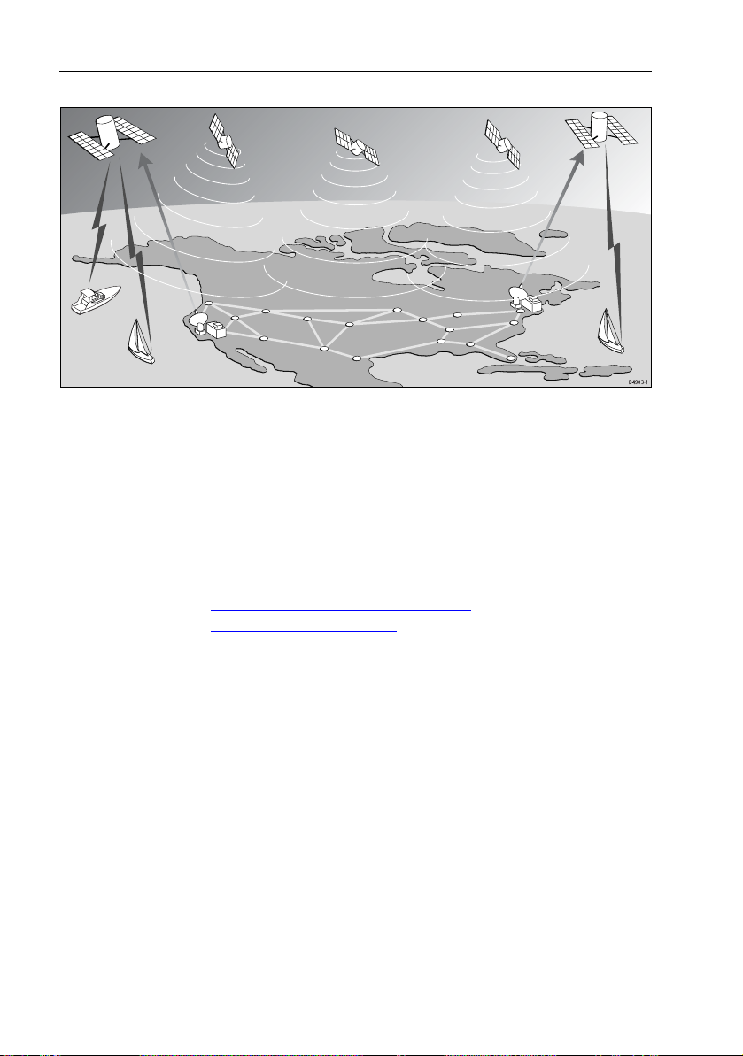
WAAS Satellite Differential GPS
W AAS provides differential augmentation to GPS. It was designed to
enhance the basic GPS service to satisfy the aviation industry’ s
navigation requirement for instrument flight rule navigation and
landing, IFR and approach landings. WAAS has been i n near
continuous broadcast since December 1999 and is also available for
other GPS applications such as marine navigation, surveying,
agriculture and automotive systems.
W AAS consists of a network of ground reference stations across the
United States that monitor GPS satellite data. The master stations
collect data from the reference stations and create a GPS correction
message, taking into account selective availability (SA), GPS
satellite orbit and clock drift, and sig nal delays caused by the
atmosphere and ionosphere. The ‘corrected’ differential messages
are then broadcast through two Geostationary Eart h Orbit (GEO)
satellites on the same frequency as the GPS signal. The Raymarine
Raynav 300 and 301GPS receiver utilizes one of its 12 channels to
‘listen’ and decode the corr ected W AAS mes sages. The result is a
DGPS system that provides improved accuracy (<3 meters) in
comparison with standard GPS (100 meters with SA, 15 m without
SA) and land based DGPS (10 meters) systems.
The W AAS system is shown diagrammatically in Figure i.
Page 4
iv Raynav 300 GPS Plotter
D4903-1
Figure i: The WAAS System
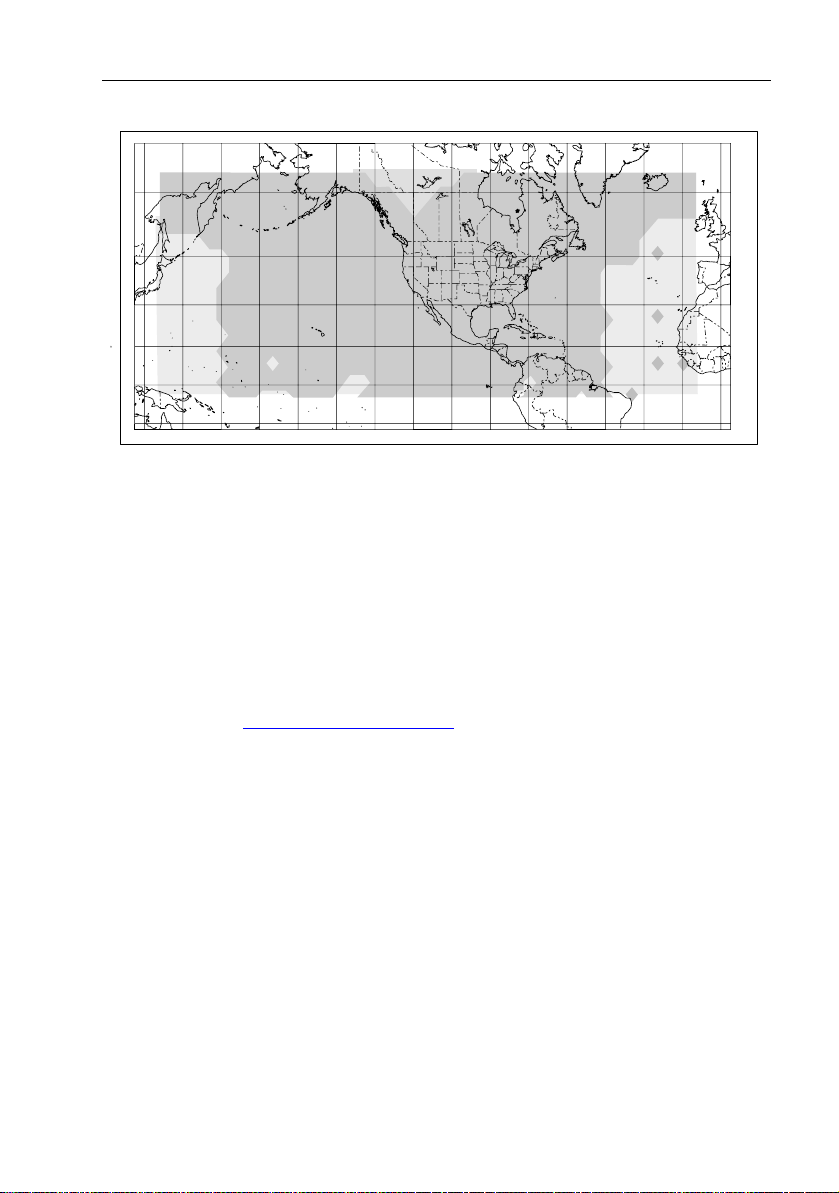
Availability of the WAAS System in North America
The W AAS system is presently broadcasting and being tested for
aviation use. It is expected to be certified by the FAA in 2002. During
this testing and certification period, continuous service is expected;
however, brief signal outages may occur as refin ements and upgrades
are made to the system. The status of W AAS an d planned outages are
available on-line at the following websites:
http://wwws.raytheontands.com/waas
or http://www.raymarine.com
Y our unit is shipped from the factory in normal GPS mode. For
improved accuracy provided by the W AAS system, you need to
enable the W AAS capability of your unit.
➤ T o enable W AAS:
1. Press the MENU key
2. Press GPS SETUP soft key
3. Press FIX MODE soft key to select SD mode.
Extended Offshore Coverage
Using two GEO satellites, W AAS provides aug mented differential
GPS coverage for most of North America. Since the W AAS
differential messages are broadcast by GEO satellites, the W AAS
signals cover a greater area both inland and offshore in comparison
with land based DGPS systems. Coverage for North America is
shown in Figure ii.
Page 5
Prelim Pages v
75˚N
60˚N
45˚N
30˚N
15˚N
0˚
15˚S
Figure ii: WAAS Coverage Map
Coverage Outside of North America
Europe and Asia are developing similar systems to WAAS called
EGNOS and MSAS respectively. Combined wit h W AAS, these
systems will provide global satellite based dif ferential GPS
augmentation into the future.
EGNOS is currently in the early testing and qualificat ion phases and
signal outages may occur at any time. The status of EGNOS and any
planned outages are available on-line at Raymarine’ s website:
http://www.raymarine.com
Y our unit is shipped from the factory in normal GPS mode. For
improved accuracy provided by the EGNOS system, you need to
enable the EGNOS capability of your unit.
0˚15˚W30˚W45˚W60˚W90˚W 75˚W105˚W120˚W135˚W150˚W165˚W 15˚E135˚E 150˚E 165˚E 180˚
D4910-1
➤ T o enable EGNOS:
1. Press the MENU key
2. Press GPS SETUP soft key
3. Press FIX MODE soft key to select SD mode.
Accuracy and Continuation of Broadcast Coverage
The navigational accuracy of equipment using these satellite
broadcast SD signals during the testing and qualificat ion phases is not
guaranteed by Raymarine Limited or Raytheon Corporation, nor is
the continuation of the broadcast SD signals the responsibilit y of
Raymarine Limited or Raytheon Corporation.
Page 6

vi Raynav 300 GPS Plotter
Preface
This handbook covers the Raynav 300 GPS Plotter manufactured by
Raymarine.
It contains important information on the installation and oper ation of
your new equipment. In order to obtain the best results in operation
and performance, please read this handbook thoroughly .
Raymarine’s Pr oduct Support representatives or your authorized
dealer are available to answer any questions you may have.
Warranty
T o register your Raynav 300 GPS Plotter ownership, please take a
few minutes to fill out the warranty registration card found at the end
of this handbook. It is important that you complete the owner
information and return the card to the factory in order to receiv e full
warranty benefits.
EMC Conformance
All Raymarine equipment and accessories are designed to the best
industry standards for use in the leisure marine environment.
The design and manufacture of Raymarine equipment and
accessories conform to the appropriate Electromagnetic
Compatibility (EMC) standards, but correct installation is required to
ensure that performance is not compromised.
Technical Accuracy
T o the best of our knowledge, the information in this handbook was
correct when it went to press. However, the Raymarine policy of
continuous product improvement may change prod uct specifications
without notice.
Consequently , unavoidable differences may occur between the
product and the handbook from time to time, for which Raymarine
cannot accept liability .
Copyright
Raymarine
SeaTalk
SmartRoute
C-MAP
©
Raymarine Limited 2001
®
is a registered trademark of Raymarine Limited.
®
is a registered trademark of Raymarine Limited.
™
is a trademark of Raymarin e Limited.
®
and C-MAP NT® are registered trademarks of C-Map s.r.l.
Page 7

Prelim Pages vii
Contents - Raynav 300 Plotter
SAFETY NOTICES......................................................................... iii
WAAS Satellite Differential GPS ............................................. iii
Availability of the WAAS System in North America ...........iv
Extended Offshore Coverage ............................................. ...iv
Coverage Outside of North America ......................................v
Accuracy and Continuation of Broadcast Coverage ..............v
Preface ........................................................................................ vi
Warranty ................................................................................vi
EMC Conformance ................................................................vi
Technical Accuracy ...............................................................vi
Chapter 1: Overview .................................................................................. 1-1
1.1 Introduction..............................................................................1-1
How this Handbook is Organized ............................................1-1
1.2 Features ....................................................................................1-2
General ....................................................................................1-2
Display ....................................................................................1-2
1.3 The Plotter Display ..................................................................1-3
Plotter Functions .....................................................................1-3
1.4 Operating Controls...................................................................1-4
Trackpad and Cursor ...............................................................1-5
Dedicated Keys .......................................................................1-6
Soft Keys ..................................... ............................................1-7
Pop-Up Menus ........................................................................1-7
Database Lists .........................................................................1-8
Chapter 2: Getting Started ....................................................................... 2-1
2.1 Introduction..............................................................................2-1
Conventions Used ...................................................................2-1
Simulator .................................................................................2-1
2.2 Power On/Off...........................................................................2-1
Changing the Lighting and Contrast ........................................2-3
2.3 Controlling the Display............................................................2-4
Selecting the Display Mode ....................................................2-4
2.4 Plotter Display Control Functions............................................2-6
Moving Around the Plotter Screen ..........................................2-6
Customizing the Display Options ...........................................2-8
Simulator Mode .......................................................................2-9
Page 8

viii
Chapter 3: Operation ..................................................................................3-1
3.1 Introduction..............................................................................3-1
3.2 Changing the Display Mode....................................................3-1
Data Display Pages ..................................................................3-2
GPS/W aypoint Data ................................................................3-3
Boat/Environment Data ...........................................................3-6
CDI/BDI Data .........................................................................3-9
Data Boxes ............................................................................3-10
Data Log ................................................................................3-11
3.3 W orking with W aypoints........................................................3-12
Introduction ...........................................................................3-12
Placing a W aypoint ...............................................................3-13
Selecting a W aypoint .............................................................3-16
W aypoint Data Display ..........................................................3-17
Editing W aypoint Details ......................................................3-17
Erasing a W aypoint ................................................................3-19
Moving a W aypoint ...............................................................3-19
Using the ST60 or ST80 Navigator Keypad ..........................3-20
3.4 W orking with Routes..............................................................3-23
Creating a New Route ............................................................3-24
Saving the Current Route ......................................................3-27
Displaying Route Information ...............................................3-28
Clearing the Current Route from the Screen ..........................3-30
Retrieve a Route from the Database ......................................3-32
Using the Route List to Erase or Name a Route .....................3-32
Editing a Route ......................................................................3-33
3.5 Following Routes and Going to W aypoints ...........................3-35
Going To an Individual T arget Point ......................................3-35
Follow a Route .......................................................................3-36
Other Follow Route Options .................................................3-37
Stop Follow or Stop Goto ......................................................3-38
Ta rget Point Arrival ...............................................................3-39
3.6 Transferring W aypoints and Routes.......................................3-40
Displayed SeaTalk Waypoints ...............................................3-40
Transferring Database Lists ...................................................3-40
3.7 Using Tracks ..........................................................................3-41
Setting Up a Track .................................................................3-42
Clearing the Current Track ....................................................3-43
SmartRoute ............................................................................3-44
Managing Tracks ...................................................................3-44
Page 9

Prelim Pages ix
3.8 Man Overboard (MOB) ........................................................3-46
3.9 Alarms & Timers...................................................................3-47
3.10 Cursor Echo...........................................................................3-49
Chapter 4: Setting Up the GPS Plotter .................................................... 4-1
4.1 Introduction..............................................................................4-1
4.2 Changing the Set Up Parameters..............................................4-2
4.3 System Set Up Parameters .......................................................4-3
Bearing Mode ..........................................................................4-4
Cursor Reference .....................................................................4-4
Cursor Readout ........................................................................4-5
Day/Night ................................................................................4-5
Help .........................................................................................4-5
Soft Keys .................................................................................4-5
Key Beep .................................................................................4-5
MOB Data ...............................................................................4-5
Autopilot Pop Up .....................................................................4-6
Menu Timeout Period ..............................................................4-6
Units ........................................................................................4-6
V ariation Source ......................................................................4-6
NMEA OUT Set Up ................................................................4-7
Cursor Echo .............................................................................4-7
Date and Time Settings ............................................................4-7
GPS Source .............................................................................4-8
GPS SOG/COG Filter .............................................................4-8
NMEA Input ............................................................................4-8
Language .................................................................................4-8
Simulator .................................................................................4-8
4.4 Plotter Set Up Parameters ........................................................4-9
Chart Orientation .....................................................................4-9
W aypoint Symbols ................................................................4-10
W aypoint Numbers ................................................................4-10
Default W aypoint Symbol .....................................................4-10
Vectors ...................................................................................4-10
Datum Selection ....................................................................4-11
Position Offset .......................................................................4-11
4.5 GPS Set Up.............................................................................4-12
Fix Mode ...............................................................................4-12
D-GPS Set Up ........................................................................4-13
Restart GPS ...........................................................................4-15
Chapter 5: Installation .............................................................................. 5-1
5.1 Introduction..............................................................................5-1
EMC Installation Guidelines ...................................................5-1
Page 10

x
5.2 Unpacking and Inspecting the Components.............................5-3
Items Missing? ........................................................................5-3
Registering this Product ..........................................................5-3
5.3 GPS Antenna Installation.........................................................5-4
Surface Mounting ....................................................................5-4
Pole Mounting .........................................................................5-6
5.4 Plotter Installation....................................................................5-7
Trunnion (yoke) Mounting ......................................................5-8
Panel Mounting .......................................................................5-9
5.5 Connecting to Other Equipment.............................................5-10
5.6 Cable Running........................................................................5-11
Introduction ...........................................................................5-11
Connectors .............................................................................5-11
5.7 System Check and Initial Switch On......................................5-14
EMC Conformance ...............................................................5-14
System Check ........................................................................5-14
Initial Switch On ....................................................................5-15
Checking the Plotter Operation .............................................5-15
Chapter 6: Maintenance & Fault Finding .................................................6-1
6.1 Maintenance.............................................................................6-1
Routine Checks .......................................................................6-1
EMC Servicing and Safety Guidelines ....................................6-1
Disposal ...................................................................................6-2
6.2 Resetting the System................................................................6-2
6.3 Problem Solving.......................................................................6-3
Appendix A: Technical Summary............................................................ A-1
Appendix B: SeaTalk and NMEA Data.....................................................B-1
Appendix C: List of Abbreviations ..........................................................C-1
GPS Antenna Mounting Template ............................................................ T-1
Raynav 300 GPS Plotter Mounting Template ......................................... T-3
Index................................................................................................................ xi
Page 11

Chapter 1: Overview 1-1
Chapter 1: Overview
1.1 Introduction
This handbook describes the Raynav 300 GPS Plotter.
Note: Many illustrations in this handbook show example screens. The
screen you see on your display depends on your system configuration and
set up options, so it may differ from the illustration.
How this Handbook is Organized
Chapter 1 - Overview (this chapter) provides an overview of the
features and functions of the Raynav 300 GPS Plotter. Y ou should read
this chapter to familiarize yourself with the GPS Plotter.
Chapter 2 - Getting Started provides an overv iew of the controls. It also
explains how to start using the GPS Plotter.
Chapters 3 - Operation provides detailed operating information for the
main plotter functions - plotting waypoints and routes, fol lowing routes,
using tracks, SmartRoute, Man Overboard and Data Lo g Mode.
Chapter 4 - Setting Up the GPS Plotter provides instructions for
setting up your GPS Plotter system to suit your preferences. Y ou should
read this chapter to determine how to set up your system preferences.
Chapter 5 - Installation provides planning considerations and detailed
instructions for installing the GPS Plotter.
Chapter 6 - Maintenance & Fault Finding provides information on
user maintenance and what to do if you experience pr oblems.
Appendix A lists the technical specifications for the GPS Plotter.
Appendix B defines the SeaT alk and NMEA data that is transferred on
integrated systems.
Appendix C provides a list of abbreviations used in this handbook.
An Index pro vides an easy lookup to specific keywords or topics.
Installation T emplates are included at the end of this h andbook.
A summary of the GPS Plotter controls and functions are provided on the
Quick Reference Card supplied with your syst em.
Page 12

1-2 Raynav 300 GPS Plotter
1.2 Features
General
The Raynav 300 GPS Plotter has a built-in GPS that provides the
following navigational signals:
• Satellite Differential GPS (eg, WAAS).
• Ground based Differential GPS, when used with an additional R TCM
beacon receiver.
• Standard GPS.
These are listed in order of accuracy and their availability is dependent
upon your location. The Raynav 300 GPS Plotter uses the best avai lable
signal to provide optimum accuracy .
The Raynav 300 GPS Plotter is waterproof to CFR46 and can be installed
either above or below deck.
The unit comprises
• Low profile ant enna
•4
½ in. LCD display comprising:
• Eight dedicated (labelled) control keys
• Four soft keys with lab els displayed on-screen
•Trackpad
The display and keys can be illuminated for nig ht-time use.
Display
• Computes positi on information from SDGPS, DGPS or GPS
• Displays and transmits SeaT alk and NMEA data
• Cursor echo across SeaT alk
• Choice of orien tation: Head Up, Course Up and North Up
Display Modes
The GPS Plotter can display data in the following modes,
cycled through by means of the
• Default GPS/W aypo int display
• Boat Data (three pages) / Environmen t Data (two pages)
• Bearing & Distance In dicator (BDI) / Course Deviation Indicator
(CDI)
• Data B oxes
• Data Log
• Plotter display
• Return to default GPS/W aypoint display
DISPLAY key:
Page 13

Chapter 1: Overview 1-3
Those modes containing more than one page of data provide additional
soft keys giving access to the sub-sets of data within each group, each
cycled through with the associated soft key.
1.3 The Plotter Display
When a position fix has been established, your vessel’ s positio n, if on
screen, is shown as a boat shape, pointing in the direction of the current
heading (or COG if heading data is not available). If no heading or COG
data is available, the vessel is shown as a circle.
A status bar at the top of the screen displays the scale, with either cursor
position, range and bearing or , when the cursor is homed (locked) to the
vessel (by pressing FIND SHIP), vessel position, Speed Over Ground
(SOG) and Course Over Ground (COG).
Note: When the cursor is homed, it is ‘locked’ to the vessel and moves
with it. The screen is automatically panned to keep the vessel and cursor
in such a position that they are 10% from the edge of the window with t he
heading vector (be it shown or not) passing through t he center of the window.
The current route is shown and any waypoints you have placed are
displayed (unless you set them to off in Set Up). Inform ation can be
viewed on-screen by positioning the cursor over a w aypoint, current
route or track.
Functions are available to control the display as follows:
• Zoom in/out
• Pan the D isplay
• Centre the Chart on the Vessel
Plotter Functions
Display Functions
The Raynav 300 GPS Plotter includes the following functions:
• Place, Move, Erase and Edit a W aypoi nt
• Goto W aypo int or Cursor
• Create, Save, Name, Edit and Follow a Route
• Review Route and W a ypoint Lists
• Display vessel’ s track; Save and Name the T rack for re-call to screen
•Use SmartRoute to make the current track in to a route
• Set Up Alarms and T imers
Page 14

1-4 Raynav 300 GPS Plotter
• Man OverBoard (MOB) to navigate back to a missing person or
object
• Data Log di splay
For systems with an autopilot, when the status and locked heading
information change, the new data can be displayed.
GPS Data Pages
Amongst a number of information pages, the GPS Data pages provide a
series of four textual displays, selected by the associated soft key . These
provide essential information associated with plotting a course for your
vessel.
•Fix status
• St eering Indication
• Position Latitud e/Longitude
• W aypoint Bearin g and Range
• Course Over Groun d (COG)
• Speed Over Ground (SOG)
• Current T ime
• Sunrise and Sunset Times
• T wilight T imes
The range of pages is detailed in Selecting the Display Mode on page 2-4.
The complete range of pages is described fully in Data Display Pages on
page 3-2.
1.4 Operating Controls
Operation utilizes a number of buttons and on-screen controls. These
include:
• A trackpad providing up, d own, left, right and diagonal control of an
on-screen cursor.
• Eight dedicated (labelled) control keys .
• Four soft keys with labels displayed on screen.
• Pop-up menus, displayed on-screen, from which options are selected.
• Databas e lists, displayed on-scre en, which enable editing of items.
Note: The cursor is the cross-hair symbol (+) visible on the display. The
trackpad moves the cursor to select a position or item on the chart.
The controls are shown in Figure 1-1. They are back-lit for night-time
use. When you use certain controls, a help message is displayed at the top
of the screen (unless you switch help off as described in Chapter 4). The
following paragraphs describe the controls and on-screen facilities.
Page 15
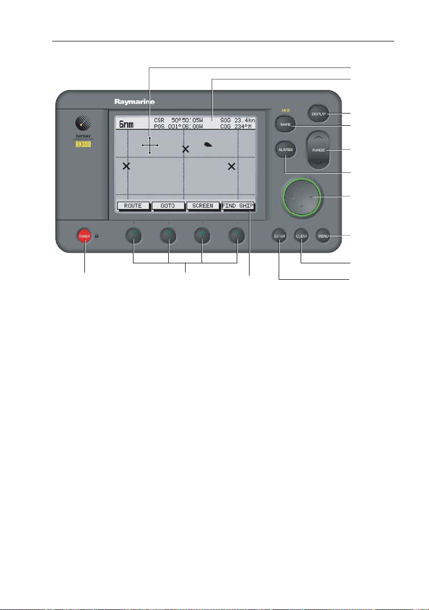
Chapter 1: Overview 1-5
Cursor
Status Bar
DISPLAY key
MARK key
RANGE key
ALARMS key
Trackpad
MENU key
POWER key Soft keys Soft key labels
Figure 1-1: Raynav 300 GPS Plotter Operating Controls
Trackpad and Cursor
The trackpad is used to:
• Move the cursor around the screen
• Select an item fr om a pop-up menu
• Adjust a variable soft key con trol
The cursor is used to:
• Select a position on the screen.
• Select and, if valid, move an item, e.g. a waypoint, on the screen.
• Select an area of the screen to zoom in to.
• Pan the d isplay .
Moving the Cursor
Press the corresponding edge of the trackpad to move the cursor
horizontally , vertically or diagonally; the longer you press, the faster the
cursor moves. The current cursor position is shown in the Status Bar at
the top of the display .
Note: When certain menus and soft keys are displayed, the cursor is not
active. If you find that you cannot move the cursor, it may be because the
unit is in one of these modes. Press CLEAR (repeatedly) until the default
soft keys are displayed; the cursor should then respond.
D4925_2
CLEAR key
ENTER key
Page 16

1-6 Raynav 300 GPS Plotter
Context-Sensitive Cursor Control
The cursor is context-sensitive. Some items on the screen have
information associated with them. Whan you place the cursor over such
objects, the information is displayed in a pop-up box. In addition, soft
keys aredisplayed for cert ain items. For example, when you p lace the
cursor over a waypoint, the waypoint data is displayed i n a pop-up box
and the waypoint soft keys are displayed.
Text Label Feature
BOX Data box (any type)
MOB Man Over Board marker
WPT Chart Waypoint
COG Course Over Ground vector
HDG Heading vector
POS Vessel’s position
RTE Route leg
TIDE Tide vector
Dedicated Keys
The dedicated keys: DISPLAY, MARK, RANGE, ALARMS, ENTER,
CLEAR, MENU and POWER have fixed functions.
Some keys can be used in two ways:
• Pr ess: Press the key momentarily and then release it. This method is
used for most key operations.
• Pr ess and hold: Press the key and hold it down for the length of time
stated (for example, 3 seconds), then release it.
When you press a dedicated key , one of the following happens:
1. The associated operation is actioned, eg. change chart scale (RANGE).
2. A pop-up menu is displayed, provi ding further options.
3. A set of soft keys is displayed, providing furth er functions.
As you press a key , a single audio beep confirms the key action. If the
key-press is invalid for the current screen or mode, three rapid beeps
sound. If required, you can turn these sounds off as part of your set up
procedure (see System Set Up Parameters on page 4-3).
Page 17
Chapter 1: Overview 1-7
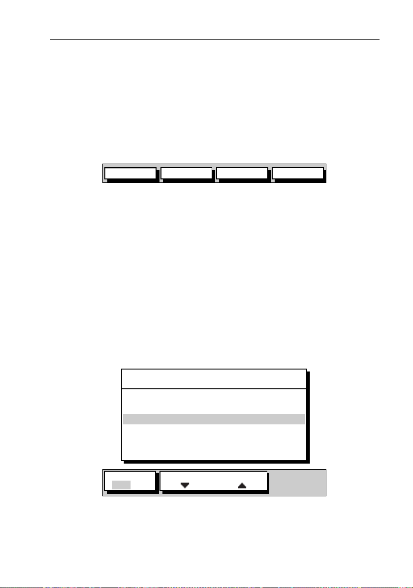
Soft Keys
The four keys below the screen are called soft keys because their
functions change according to the operation. The soft keys are grouped
into related sets and subsets providing access to the various functions.
The soft key labels are displayed on the screen just above the keys. The
default soft keys are displayed until you press a key , or select an item on
the screen; the soft keys asso ciated with the action ar e then displayed as
shown in Figure 1-2.
GOTO SCREENROUTE FIND SHIP
D4897-1
Figure 1-2: Default Soft Keys
Note: If the key text is greyed out, it is not currently available.
When you press a soft key , one of the following happens:
1. The associated operation is actioned.
2. A sub-set of soft keys is displayed, providi ng further functions.
3. A pop-up menu is displayed, providing furt her options.
As with dedicated keys, soft key operations ar e confirmed (or denied) by
key beeps, see Dedicated Keys above.
Pop-Up Menus
Pop-up menus usually provide set up options. When a pop-up menu is
on-screen, a set of associat ed soft keys is also displayed as shown in
Figure 1-3.
ALARMS SET UP
ARRIVAL ALARM
OFF TRACK ALARM
ANCHOR ALARM
COUNTDOWN TIMER
ALARM CLOCK
ALARM
OFF ON
SELECT DISTANCE
Figure 1-3: Typical Pop-up Menu
Use the trackpad to select an option from the menu, then use the
appropriate soft key to set the option. For example, you can togg le the
ANCHOR ALARM on/off using the soft key s.
0.01nm
ON
OFF
00:10:00
OFF
D4898_2
Page 18
1-8 Raynav 300 GPS Plotter
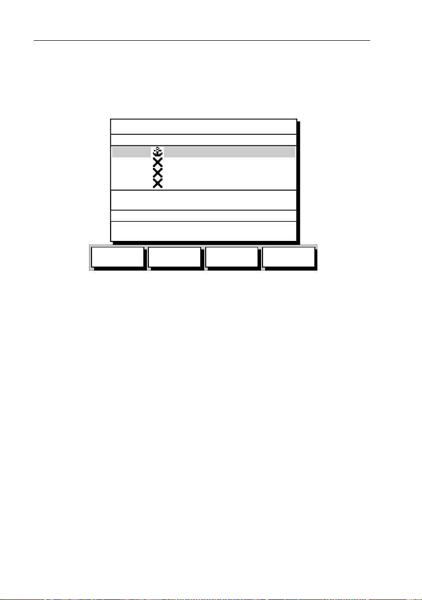
Database Lists
The waypoints, routes and tracks created on the display unit are stored in
database lists. You can view these lists and select items for editing as
shown in Figure 1-4 .
WAYPOINT LIST
SYMBOL NAME
WPT 001
WPT 002
WPT 003
WPT 004
POSITION
BRG 348°m
TEMP 20°C
DATE 23/11/01
N 50°50^000
W 001°06^000
RNG 1.00nm
DEPTH 12.3m
TIME 08:45:12
GOTO
WAYPOINT
EDIT
WAYPOINT
MAKE NEW
WAYPOINT
WAYPOINT
TRANSFER
D4906-2
Figure 1-4: Typical Waypoint List
As with pop-up menus, when a database list is on-screen, a set of
associated soft keys is also displayed. Use the trackpad to select an item
from the list, then use the appropriate soft key to select the function.
Page 19

Chapter 2: Getting Started 2-1
Chapter 2: Getting Started
2.1 Introduction
This chapter provides information, instructions and a simple
familiarization exercise in using the display . Operating information is
detailed in Chapter 3.
Conventions Used
Throughout this handbook, the dedicated (labelled) keys are shown in
bold capitals; for example, ENTER. The soft key functions, menu names
and options are shown in normal capitals; for example, SCREEN.
Operating procedures, which may consist of a singl e key-press or a
sequence of numbered steps, are indicated by a ➤ symbol in the margin.
Simulator
The plotter display unit includes a Simulator mode, which allows you to
practice operating your plotter without data from a G PS antenna. Y ou
will need to use the set up options to switch the display unit to Simulator
mode, see Section 2.2, Power On/Off. Y ou can use it in ei ther of two
ways:
• Before the plotter has been installed on your vessel. In this case, you
only need to connect the plotter display unit to a 1 2V DC power supply , fused at 1A, connecting the red core from the power lead to positive (+) and the black core to negative (-); see Cable Running on page
5-11 for full d etails.
• After the plotte r has been installed on your vessel, but while in the
marina or at anchor .
2.2 Power On/Off
➤ T o turn the display unit on, press the POWER key.
The keys light up and the introductory logo is disp layed.
The GPS Status screen is displayed as shown in Figure 2-1.
Page 20
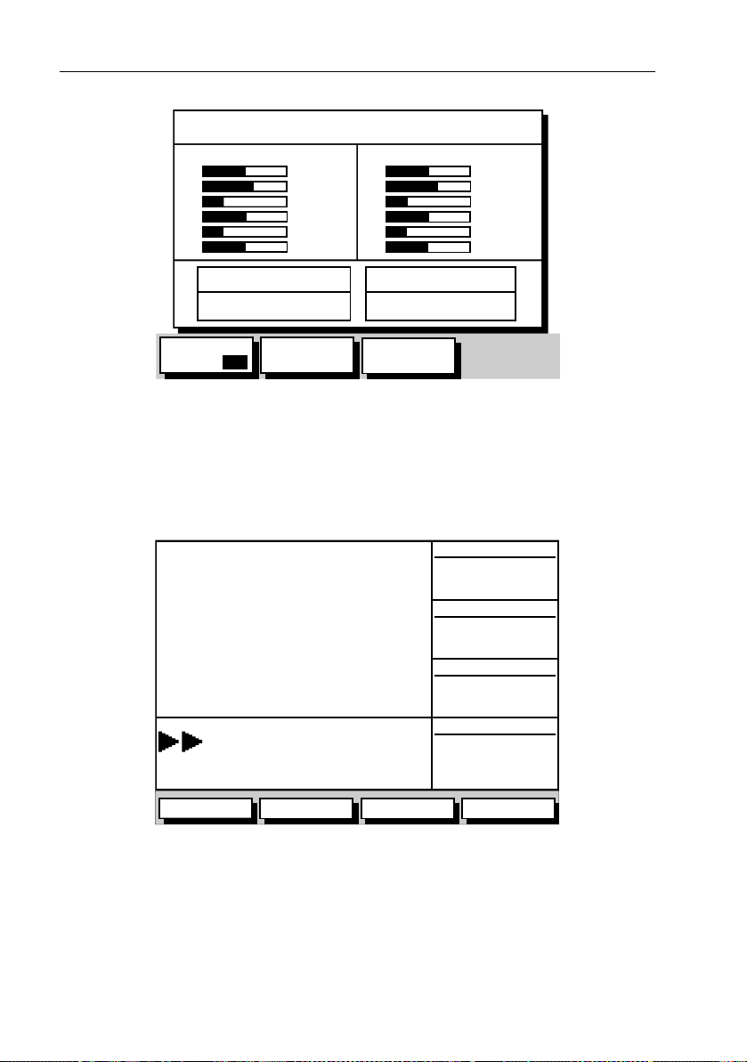
2-2 Raynav 300 GPS Plotter
GPS STATUS
SAT SIGNAL STATUS
15
09
08
10
20
17
LOCKED
IN USE
IN USE
LOCKED
LOCKED
LOCKED
HDOP FIX STATUS
SAT SIGNAL STATUS
23
18
26
12
14
03
LOCKED
IN USE
IN USE
LOCKED
LOCKED
LOCKED
1.0 D-FIX
FIX MODE
GPS D SD
D-GPS
SET UP
RESTART
GPS
D5551_1
Figure 2-1: GPS Status Screen
The GPS Status screen is displayed until a satellite fix has been acquired.
When satellite acquisition is complete, the READY FOR NAVIGATION
pop-up box displays for two seconds.
T o proceed whilst satellite acquisition continues, press the CLEAR key;
the GPS Data Screen is displayed.
SD-FIX
WPT BRG
320°M
50°50^000N
WPT RNG
0.55nm
001°06^000W
COG
050°M
STEER STARBOARD
WPT 004
GOTO GPS DATAROUTE WPT DATA
Figure 2-2: GPS Data Screen
➤ T o switch the display unit off, press and hold the POWER key for at least
three seconds. A 3-second countdown timer is displayed; when it reaches
SOG
12.0kts
D4936-1
Page 21
Chapter 2: Getting Started 2-3
CONTRASTLIGHT
ON
42% 60%
zero the display and key backlights extin guish. If the POWER key is
released within this period, power-down is cancelled.
Changing the Lighting and Contrast
Y ou can change the level of b acklighting and contrast for the screen and
keys. The key backlighting always retains a minimal level to enable the
keys to be seen at night.
➤ T o change the lighting and contrast:
1. Press the POWER key to display the lighting controls (Figure 2-3).
D4927_1
Figure 2-3: Lighting Controls
2. Use the LIGHT soft key or trackpad left/right to select LIGHT contr ol.
•Use the LIGHT so ft key to toggle lighting ON/OFF.
• Use trackpad up/down to select lighting level (eight levels).
3. Press the CONTRAST soft key , or trackpad left/right, to select the CON-
TRAST cont rol. Adjust the contrast setting in the same way as for the
lighting (100 contrast levels).
4. Press ENTER to remove the soft key sliders and return to the default
screen, with the new lighting and contrast levels retained.
When the display unit is switc hed on, screen lighting is restored to ON if
it was ON previously . Whilst the unit is switched on, the chosen lighti ng
level is retained until it is reset. The new contrast level is retained until it
is reset, even after power-off, unless it has been set eit her very low or very
high; in this case, the contrast will be restored on power -up as follows:
• Contrast set <30% restored to 30%
• Contrast set >70% restored to 70%
Note: Factory default settings are LIGHT OFF and CONTRAST 50%.
Page 22

2-4 Raynav 300 GPS Plotter
2.3 Controlling the Display
The display is controlled by means of the cursor and control keys. Most
plotter operations are started from the default soft k eys displayed in the
plotter screen (Figure 2-4).
GOTO SCREENROUTE FIND SHIP
Figure 2-4: Default Soft Keys
On completion of an action using the soft keys, press CLEAR to return to
the default screen; you may need to press CLEAR several times to
back-track through the soft key hierarchy.
Note: If you have set up your system so that the default soft keys are not
permanently displayed, press any soft key to display the labels.
Selecting the Display Mode
The DISPLAY key is used to select the desired display mode. The
following modes can be selected.
➤ Select the following modes by repeat presses of the DISPLAY key
(Figure2-5):
• GPS/W aypoint display
• Boat Data (three pages)-Environment Data (two pages)
• Course Deviation In dicator (CDI)-Bearing/Distance Indicator (BDI)
• Data B oxes
• Data Log
• Plotter display
• Return to GPS/Waypoint display
The complete ranges of pages available in Boat and Environment Dat a
modes are described in Chapter 3.
D4897-1
Page 23
Chapter 2: Getting Started 2-5
Press
POWER
... after preliminary displays, the default display is shown
Waypoint data
SD-FIX
SD-FIX
SD-FIX
GPS data
SD-FIX
Press
DISPLAY
to return to
GPS/Waypoint
Data
CSR 50°50^05W SOG 23.4kn
6nm
POS 001°06^00W COG 234°M
GOTOROUTE SCREEN FIND SHIP
DISPLAY
Press to show
Plotter Display
TIME POSITION CMG DMG
09:00 50°50^000N 239°m 4.8nm
20/12 001°06^000W
09:30 50°51^000N 241°m 5.2nm
20/12 001°07^000W
10:00 50°52^000N 240°m 4.5nm
20/12 001°08^000W
ROUTE
GOTO
STOP LOG
50°50^000W
001°06^000W
ROUTE GOTO GPS DATA WPT DATA
CLEAR LOG
SD-FIX
SD-FIX
SD-FIX
STEER STARBOARD
WPT 004
STEER STARBOARD
WPT 004
Note: In any display mode
press DISPLAY key for 2 seconds
to return to default display.
OWN POS
XTE
XTE
XTE
320°M
WPT BRG
WPT RNG
WPT BRG
WPT BRG
0.55nm
COG
352°M
WPT RNG
0.55nm
COG
050°M
GPS DATA WPT DATA
SOG
12.0kts
050°M
SOG
12.0kts
SOG
SOG
WPT DATA
WPT DATA
WPT DATA
SOG
SOG
SOG
WPT DATA
WPT DATA
Environment data
SD-FIX
SD-FIX
Boat data
SD-FIX
DEPTH 12.5m
SPEED 11kts
ROUTE GOTO BOAT DATA ENVIROMNT
ROUTE
Press
DISPLAY
to show
Boat/Environment
Data
APPARENT WIND
TRUE WIND
0.55nm
GPS DATA WPT DATA
12.0kts
DISPLAY
225°T
10
WPT BRG
320°M
WPT RNG
050°M
DEPTH 12.5M
SPEED 11kts
STEER STARBOARD
WPT 004
STEER STARBOARD
WPT 004
Press to show
CDI or BDI
355°T
40 40
30 30
20 20
nm nm
10
STEER STARBOARD
STEER STARBOARD
WPT 004
WPT 004
GOTO CDI
WIND
WIND
WPT BRG
WPT BRG
WPT RNG
COG
050°M
SOG
SOG
COG
SOG
SOG
WPT DATA
SOG
WPT DATA
WPT DATA
XTE
0.05nm
XTE
WPT BRG
0.05nm
300°T
WPT BRG
WPT RNG
300°T
23.2nm
WPT RNG
TTG
23.2nm
04
h 12m
TTG
BDI BDI
04
h:12m
BDI
Press
DISPLAY
to show
Data Log
WPT RNG WPT BRG PILOT
28.7nm
TIME SPEED COG
10:40:18
DEPTH POSITION
36.5ft
124°T
17kts
50°50^000N
001°06^000W
GOTOROUTE
MANUAL
124°T
15.1kts
Figure 2-5: Display Modes
SOG
Press
DISPLAY
to show
Data Boxes
D4964-2
Page 24

2-6 Raynav 300 GPS Plotter
2.4 Plotter Display Control Functions
Y ou will normally operat e the GPS Plotter with the display showing one
of the Navigation Data pages.
The range of pages is listed in Selecting the Display Mode on page 2-4
and illustrated in Figure 2-5. The complete range of pages is described
fully in Data Display Pages on page 3-2.
Moving Around the Plotter Screen
When using the plotter screen, the default orientation is North-Up, where
the vessel moves across the screen. Y ou will need to pan the display if
your vessel moves out of the current area, or if you wish to examine or
place waypoints in another area. Alternatively , you can home the cursor
onto the vessel using FIND SHIP.
There are four ways in which you can move around the display:
• Use the trackpad to pan the display .
• Automatically home (re-center) the vessel using the FIND SHIP soft
key.
• Use the context-sensitive cursor to change the display cent er.
• Change the display scale to zoom out and in to a new area centered on
the cursor position. This method is useful if the area you wish to see is
a long distance away.
Panning the Display
Panning the display is useful if the area you wi sh to see is only just off the
screen.
➤ Use the trackpad to move the cursor to the edge of the d isplay; the display
will pan across.
Using FIND SHIP
FIND SHIP is used to center the vessel on the screen, even if it is currently
off screen:
➤ Press the FIND SHIP soft key; the following actions occur:
• The display is re-drawn with the vessel ’s position i n the center .
• The cursor is homed (locked) to the vessel’ s position and moves with
it.
• When the vessel moves near the edge of the screen, th e display is
redrawn to place the vessel and cursor at the center.
• Whilst homed, th e status bar indicates vessel position, speed and
course over ground.
Page 25

Chapter 2: Getting Started 2-7
➤ T o release the cursor from homed mode, use the trackpad to move the
cursor away from the vessel’ s current position. The status bar shows the
current cursor position, bearing and range. The cursor no longer moves
with the vessel and no redraw occurs if the vessel moves off scr een.
Changing the Display Center
Y ou can move the area of the display center using the context-sensitive
cursor. This all ows you to center your vessel in the center of the screen, or
to move the display so that your vessel is displayed off-cen ter anywhere
on the screen.
➤ T o move your vessel’ s position off-center:
1. Move the cursor over your vessel’s position until the letters POS are
displayed.
2. Press ENTER to take control of the vessel’s position. The letters POS
are now in inverse video and the cursor symbol has changed to a
four-way arrow . This indicates that the cursor can be used to move the
display in any direction.
3. Use the trackpad to move the cursor to the required position.
4. Press ENTER to select the position and return to normal cursor con-
trol. The display is redrawn with the vessel’ s position at the cursor .
Alternatively, you can press CLEAR to abandon the move and leave
the display (and vessel) in its former position.
➤ To center the display:
1. Use the trackpad to move the cursor to the vessel’s position. The cursor text POS is displayed.
2. Press CLEAR. The display pans to show your vessel’ s position is in
the center of the screen.
Changing the Display Scale
The RANGE key allows you to change the display scale so that you can
see a smaller or larger area on the screen.
Y ou can change the display scale:
• T o see either a larger scale (of a smaller area) or a larger area (at a
smaller scale) on the screen.
• T o move the display to anot her area, by zooming out to a smaller
scale, then zooming in on another position cent ered on the cursor .
Each time you press the RANGE key , the display scale changes to the next
available setting. The status bar, shown in Figure 2-6, indicates the
distance from top to bottom of the screen, in nautical miles.
Page 26

2-8 Raynav 300 GPS Plotter
6nm
VES 43°27^05N
POS 001°02^83W
Figure 2-6: Status Bar
SOG 23.4kts
COG 234°M
D4902-1
➤ T o change the scale rapidly , press and hold top or bot tom of the RANGE
key.
The distance indicator at the left-hand side of the status bar is updated
whenever you change the display scale.
➤ T o zoom in to a larger-scal e (more detailed) display:
1. Use the trackpad to position the cursor in the area you wish to see in
larger scale.
2. Press the bottom of the RANGE key to zoom into the area.
The display, centered on the cursor , is enlarged to show a larger scale
and the distance indicated in the status bar is updated.
➤ T o zoom out to a smaller-scale (less detailed) display, press the top of the
RANGE key as many times as required, up to the maximum scale of
1200nm.
Customizing the Display Options
The SCREEN soft key enables the following screen display options to be
set on or off:
• Cursor Box (CRSR BOX)
•Grid (GRID)
• Personalized (CUSTOM)
The factory default for these options is ON.
Switching the Cursor Data Box On/off
The cursor data box provides the cursor’s p osition in latitude/longitude
and/or bearing/range.To see a full image, switch the data box off.
➤ T o control the cursor data box:
1. Press the SCREEN soft key.
2. Press the CRSR BOX soft key to toggle the setting between ON and OFF.
T o return to the default soft key display , press CLEAR.
➤ T o move the cursor box:
1. Use the trackpad to position the cursor over the box until the letters
BOX are displayed.
2. Press ENTER to take control of the box, use the trackpad to move it to
the required position and press ENTER again.
Page 27

Chapter 2: Getting Started 2-9
Switching Grid On/off
The Plotter display can be set to show grid lines of latitude and longitude
which can help determine position.
➤ T o turn the grid on or off:
1. Press the SCREEN default soft key.
2. Press the CHRT GRID soft key to toggle the setting ON and OFF.
3. To return to the default soft key display , press CLEAR.
Simulator Mode
When simulator mode is started, your initial simulated p osition is
wherever the cursor was last positione d. T o practice using the Plotter in a
particular area, use the tr ackpad to pan to that area, then switch simulator
ON.
A data box indicating SIMULATOR ON is displayed in the center of the
screen (this may obscure the cursor; if necessary use the trackpad to move
the cursor into view). Y ou can use the context-sensitive cursor to move
this box
Note: If you use FIND SHIP when in Simulator mode, the Status Bar at the
top of the screen shows SIM FIX. If real position data is available (via
GPS) and the simulator is active, simulated data takes precedence.
On power-up the simulator defaults to its previous setting at last p ower-down. Care should be taken to determine desired mode on power-up.
Simulated data should never be used for navigational purposes.
Any waypoints placed on the plotter in simulator mode are retained in the
W aypoint List and are available for use in routes.
➤ T o view a simulated display:
1. Press MENU followed by the SYSTEM SET UP soft key . The System Set
Up menu pop-up is displayed.
2. Use the trackpad up/down to move the selection bar over the option
SIMULATOR. The simulator soft keys are displayed.
3. Press the ON soft key to start simulation.
4. Press ENTER twice to return to the default display .
Page 28

2-10 Raynav 300 GPS Plotter
Page 29

Chapter 3: Operation 3-1
Chapter 3: Operation
3.1 Introduction
This chapter explains how to navigate with the Raynav 300 GPS Plotter.
It covers the following topics:
• Controlling waypoints, including placing, moving, editing and deleting waypoints.
• Changing the display mode.
• Using a range of data pages to displ ay navigation data.
• Maintaining a Data Log of T ime, Position, Course Made Good
(CMG) and Distance Made Good (DMG).
• W orking with wayp oints and routes, including creating a new route,
managing routes using the Route List and editing routes.
• Following routes an d going to waypoints.
• T ransferring waypoints and routes
• Using tracks, including sho wing tracks, track set up, saving tracks
and converting a track to a route (SmartRoute).
• Using the Man Overboard (MOB) feature.
• Setting up Al arms and Timers .
• Cursor echo from other equipm ent.
CAUTION:
The GPS Plotter makes it easy to place a waypoint and travel
towards it. However , you should always check first that the route is
safe. When using the GPS Plotter in combination with a SeaT alk
autopilot, the autopilot will prompt for confirmation before it steers
the vessel towards the waypoint.
3.2 Changing the Display Mode
The DISPLAY key is used to select the desired screen mode. The
following modes can be selected:
• Default GPS/W aypoi nt display
• Boat Data (three pages) / Environment Data (two pages)
• Course Deviation Indicator (CDI)/Bearing & Distance Indicator
(BDI)
• Data Boxes
• Data Log
• Plotter display
• Return to default GP S/W aypoint display
Page 30

3-2 Raynav 300 GPS Plotter
The modes that contain more than one page of data provide additional
soft keys which cycle through the pages. The highli ghted soft key
indicates the screen mode currently displayed.
Note: Press the DISPLAY key for at least two seconds in any display
mode to return to the GPS/W ayp oi nt display.
Data Display Pages
In all graphical display pages, the steering instruction is STEER
STARBOARD if the XTE is 0.01nm or more to port, STEER PORT if the XTE
is 0.01nm or more to starboard or ON COURSE if XTE is less than 0.01 on
either side.
If no Goto or follow is in progress, the steering instruction is NOT
FOLLOWING and no steering arrows are shown.
The arrows either side of the steering instruction and pointing towards it
are dependent on the XTE. The first arrow is shown when the diff erence
reaches 0.01nm and the second at 0.05nm.
T extual data provides Position, SOG, COG , Bearing and Range to
waypoint, Time and Date, T ime T o Go (TTG), Steering Indicator,
Sunrise, Sunset, Fix Status and XTE. Any unavailable d ata is replaced by
dashes, one per character . When there is no GPS fix but there is a value for
the last fix, this is shown instead.
The waypoint name is shown unless there is no target, in which case NOT
FOLLOWING is shown. If Goto cursor is in progress, GOTO CURSOR is
shown.
The FIX status indi cates D-FIX for a differential fix, SD-FIX for a satellite
differential fix, FIX for a GPS or other Fix, or NO FIX where a fix has not
been acquired. If the simulator is ON, the word SIMULATOR appears after
the fix status.
BRG , RNG and XTE data relate to the target waypoint.
Time refers to local time zone which is set in the System Set Up menu, see
Chapter 4.
The Time T o Go (TTG) and Estimated T ime of Arrival (ETA) data relate
to the target waypoint (not the whole route) and are based on the Speed
Over Ground (SOG) towards the target. If the Velocity Made Good
(VMG) is negative, or data is not available, these fields are replaced by
dashes, one per character.
Sunrise and Sunset times are for today and at the vessel’ s position.
Page 31

Chapter 3: Operation 3-3
GPS/Waypoint Data
GPS Data
The GPS Data display comprises four text data pages, selected in turn by
the GPS DATA soft key. These pages are shown in Figure 3-1 to
Figure 3-4.
SD-FIX
WPT BRG
320°M
WPT RNG
50°50^000N
001°50^000W
STEER STARBOARD
WPT 004
ROUTE GOTO GPS DATA WPT DATA
Figure 3-1: GPS Data Page #1
SD-FIX
0.55nm
COG
050°M
SOG
12.0kts
WPT BRG
320°M
WPT RNG
COG
SOG
ROUTE GOTO GPS DATA WPT DATA
320°
12.5
STEER STARBOARD
WPT 004
Figure 3-2: GPS Data Page #2
M
kts
0.55nm
POSITION
50°50^000N
001°06^000W
TIME
12:34:00
D4936-2
D4937-2
Page 32

3-4 Raynav 300 GPS Plotter
SD-FIX
WPT BRG
320°M
WPT RNG
12:34:00
23/02/00
STEER STARBOARD
WPT 004
ROUTE GOTO GPS DATA WPT DATA
Figure 3-3: GPS Data Page #3
SD-FIX
0.55nm
COG
050°M
SOG
12.0kts
TWILIGHT
05:30
SUNRISE
12:34:00
23/02/00
STEER STARBOARD
WPT 004
ROUTE GOTO GPS DATA WPT DATA
Figure 3-4: GPS Data Page #4
06:43
SUNSET
18:00
TWILIGHT
18:54
D4938-2
D4939-2
Page 33

Chapter 3: Operation 3-5
Waypoint Data
The W aypoint Data display comprises three data pages, selected in turn
by the WPT DATA soft key . These pages are shown in Figure 3-5 to
Figure 3-7:
SD-FIX
XTE
0.06nm
TTG
BRG
RNG
ROUTE GOTO GPS DATA WPT DATA
SD-FIX
320°
0.55
STEER STARBOARD
WPT 004
Figure 3-5: Waypoint Data #1
M
nm
01h:00m
COG
050°M
SOG
12.0kts
XTE
0.06nm
TTG
BRG
RNG
ROUTE GOTO GPS DATA WPT DATA
320°
0.55
STEER STARBOARD
WPT 004
Figure 3-6: Waypoint Data #2
M
nm
01h:00m
ETA
13:34:00
TIME
12:34:00
D4940-2
D4941-2
Page 34

3-6 Raynav 300 GPS Plotter
SD-FIX
BRG
RNG
ROUTE GOTO GPS DATA WPT DATA
Boat/Environment Data
Boat Data
The Boat Data display comprises three data pages, selected in turn by the
BOAT DATA soft key. These pages ar e shown in Figure 3-8 to Figure 3-10:
SD-FIX
DEPTH
320°
0.55
STEER STARBOARD
WPT 004
Figure 3-7: Waypoint Data #3
12.5
M
nm
m
OWN POS
50°50^000N
001°06^000W
WPT POS
50°50^000N
001°06^000W
COG
050°M
SOG
12.0kts
D4942-2
WPT BRG
320°M
WPT RNG
0.55nm
COG
SPEED
ROUTE GOTO BOAT DATA ENVIROMNT
11
kts
STEER STARBOARD
WPT 004
Figure 3-8: Boat Data #1
050°M
SOG
12.0kts
D4943-2
Page 35

Chapter 3: Operation 3-7
SD-FIX
WPT BRG
320°M
WPT RNG
DEPTH
TEMP
ROUTE GOTO BOAT DATA ENVIROMNT
SD-FIX
12.5
11°
STEER STARBOARD
WPT 004
Figure 3-9: Boat Data #2
M
C
0.55nm
COG
050°M
SOG
12.0kts
PILOT
AUTO
RUDDER
HDG
LOCK
ROUTE GOTO BOAT DATA ENVIROMNT
325°
323°
STEER STARBOARD
WPT 004
Figure 3-10: Boat Data #3
M
M
---
COG
050°M
XTE
0.05nm
D4944-2
D4945-2
Page 36

3-8 Raynav 300 GPS Plotter
Environment Data
The Environment Data display comprises two data pages, selected in turn
by the ENVIRONMT soft key. These pages are sho wn in Figure 3-11 and
Figure 3-12.
WIND (TRUE)
WIND
SSW 7
RUDDER
105°
32.0
STEER STARBOARD
ROUTE GOTO BOAT DATA ENVIROMNT
WIND (APP)
STBD
kts
WPT 004
Figure 3-11: Environment Data #1
050°M
320°M
---
COG
HEADING
WIND
SSW 7
RUDDER
105°
32.0
STEER STARBOARD
ROUTE GOTO BOAT DATA ENVIROMNT
STBD
kts
WPT 004
Figure 3-12: Environment Data #2
050°M
320°M
---
COG
HEADING
D4946-2
D4947-2
Page 37

Chapter 3: Operation 3-9
CDI/BDI Data
The Course Deviation Indicator (CDI) / Bearing Deviation Ind icator
(BDI) display comprises two data pages, selected alternately by the CDI
and BDI soft keys. These pages are shown in Figure 3-13 and
Figure 3-14:
CDI Data
The CDI display shows Cross Track Error (XTE) and Distance to
W aypoint presented in a ‘runway’ format as shown in Figure 3-13:
355°T
XTE
0.05nm
WPT BRG
300°T
WPT RNG
23.2nm
TTG
STEER STARBOARD
WPT 004
GOTO CDIROUTE BDI
Figure 3-13: CDI Display
The ‘runway’ represents a 0.3nm width with the vessel sy mbol shown at
the bottom. Individual text boxes show Cross T rack Error (XTE),
Bearing to W aypoint, Distance to Wa ypoint and Time to Go (TTG). TTG
is calculated on the basis of distance to destination and V e locity Made
Good (VMG) towards destination.
At waypoint ranges greater than 4nm, the symbol remains at the top of t he
screen. As the waypoint range falls below 4nm, the symbol moves down
the centre line.
The checkered pattern moves down the screen to simulate movement
when SOG is greater than 2 knots (0.5knots if D-FIX or SD-FIX).
04
h:12m
D4932-2
BDI Data
The BDI graphical display shows deviation from the Bearin g to
W aypoint and Distance to W aypoint as shown in Figure 3-14. Individual
text boxes show Cross Track Error (XTE), Bearing to W aypoint,
Distance to W aypoint, Time to Go (TTG). TTG is calculated on the basis
Page 38

3-10 Raynav 300 GPS Plotter
of distance to destination and V elocity Made Good (VMG) towards
destination.
40
nm nm
The line to the waypoint symbol is shown at an angle eq ual to the
difference between the COG and the Bearing to W aypoint to a maximum
±15°. The waypoint symbol is the symbol of the targ et waypoint as
of
shown on the display .
Four range arcs are shown with automatic scaling to provide 0.4nm, 1nm,
5nm, 10nm, 25nm, 50nm, 100nm, 200nm, 400nm, 1000nm, 20 00nm and
4000nm range scales. In each case the range scale has graduations at ¼, ½
and ¾ of the current scale.
Data Boxes
The Data Boxes display is shown in Figure 3-15.
225°T
30
20
10
10
STEER STARBOARD
WPT 004
GOTO CDIROUTE BDI
Figure 3-14: BDI Display
20
30
40
XTE
0.05nm
WPT BRG
300°T
WPT RNG
23.2nm
TTG
h:12m
04
D4933-2
WPT RNG WPT BRG PILOT
28.7nm
TIME SPEED COG
10:40:18
DEPTH POSITION
36.5ft
Figure 3-15: Data Boxes Screen
124°T
17kts
50°50^000N
001°06^000W
GOTOROUTE
MANUAL
124°T
15.1kts
SOG
D4934-2
Page 39

Chapter 3: Operation 3-11
Data Log
The GPS Plotter can be set to log passage data every 30 minutes. Up to 48
log entries are held. When 48 entries have been saved, the first entries
start being overwritten.
If the number of log entries exceeds the table size, use the trackpad
up/down to scroll the list and view further log entries. Each line i n the log
shows:
• T ime of log entry
• Position at ti me of log entry
• Course Made Good (CMG) since last lo g entry
• Distance Made Good (DMG) since last log entry
Y ou can stop the log at any time and you can clear the log from memory .
➤ T o use Data Log Mode:
1. Press DISPLAY repeatedly until the Data Log table is displayed.
2. Press the START LOG soft key to start logging; the START LOG soft key
changes to STOP LOG.
At 30 minute intervals, the current time, vessel’ s position, distance made
good (DMG) and course made good (CMG) are recorded as shown in
Figure 3-16.
TIME POSITION CMG DMG
09:00 50°50^000N 239°m 4.8nm
20/12 001°06^000W
09:30 50°51^000N 241°m 5.2nm
20/12 001°07^000W
10:00 50°52^000N 240°m 4.5nm
20/12 001°08^000W
GOTO STOP LOGROUTE CLEAR LOG
Figure 3-16: Data Log Screen
3. Press the STOP LOG soft key to stop log ging.
4. Press the CLEAR LOG soft key to clear all log entr ies.
D4924-1
Page 40

3-12 Raynav 300 GPS Plotter
3.3 Working with Waypoints
Introduction
Y ou can place up to 998 waypoint s on the GPS Plotter.
A waypoint is a position entered on the display as a reference or
destination point. All waypoints placed on the GPS Plotter are stored in a
waypoint database list which includes symbol, position, bearing, range
and additional data. All waypoints in the database are displayed on the
plotter screen, unless you set waypoint display of f in the Set Up menu, as
described in Chapter 4. Y ou can select a waypoint, either graphically or
from the W aypoint List, for editing .
The waypoint can be placed either at the current cursor posi tion or
numerically at the current vessel’ s position. W aypoints can also be
entered manually as either Lat/Long coordinates or Loran TDs which are
automatically converted to Lat/Long coordinates. A waypoint placed at
the vessel’s po sition includes additional information (if available)
providing depth, temperature and time when it was placed. A ny type of
waypoint can be included in a route.
Note: You can place waypoints before you install the GPS Plotter on
your vessel.
When a new waypoint is placed, it uses either the factory defau lt symbol
(a cross) or an alternative symbol available from the Set Up menu, see
Chapter 4. The waypoint is added to the W aypoint List and tagged with
the next available number . The waypoint’ s symbol and name can be
edited at any time. When the cursor is positioned over a waypoint, the
waypoint bearing and range are displayed in a pop- up box.
W aypoints in the current route are available on other SeaTalk instruments
that support current route transfer, for example, an ST80 Masterview .
Y ou can also transfer waypoints between the GPS Plotter and other
NMEA or SeaT alk instruments using the W aypoint T ransfer functions.
This section explains how to perform the followi ng tasks using the
on-screen cursor and the waypoint list:
• Placing a W aypoint
• Selecting a W aypoint
• Displaying W ay point data
• Editing a W aypoint (symbol, name & position)
• Erasing a W aypoint
• Moving a Waypoint
Page 41

Chapter 3: Operation 3-13
At the end is a section about using the ST60/80 Navigator Keypad to
select, edit and name your waypoints.
Placing a Waypoint
➤ T o access the Place W aypoint soft keys, press MARK; the Place
W aypoint soft keys are displayed as shown in Figur e3-17:
PLACE WPT
AT CURSOR
PLACE WPT
AT VESSEL
WAYPOINT
LIST
D4905-1
Figure 3-17: Waypoint Soft Keys
➤ T o place a waypoint at the cur sor (plotter screen) or the vessel’s current
position:
1. Press either the PLACE WPT AT CURSOR or the PLACE WPT AT VESSEL
soft key . The waypoint is added to the W aypoint List and tagged using
the next available number.
If you place a waypoint at the cursor , the W aypoint soft keys shown
in Fi gure 3-23 are shown. Press CLEAR to remove these softkeys.
2. Press CLEAR to rem ove the Place W aypoint soft keys.
➤ T o place a waypoint as a latitude/longitude position usi ng the W aypoint
List:
1. Press MARK, followed by the WAYPOINT LIST soft key; the Wayp oint
List and associated soft keys are displayed as shown in Figure 3-18:
WAYPOINT LIST
SYMBOL NAME
WPT 001
WPT 002
WPT 003
WPT 004
POSITION
BRG 348°m
TEMP 20°C
DATE 23/11/01
N 50°50^000
W 001°06^000
RNG 1.00nm
DEPTH 12.3m
TIME 08:45:12
GOTO
WAYPOINT
EDIT
WAYPOINT
MAKE NEW
WAYPOINT
WAYPOINT
TRANSFER
D4906-2
Figure 3-18: Waypoint List and Soft Keys
The list details all waypoints in alpha-numerical order . The selected
waypoint is indicated by the highlight bar; its position in Lat/Long,
Page 42

3-14 Raynav 300 GPS Plotter
bearing and range, date, time and, if placed at vessel, depth and temperature (if available) are shown.
2. Press the MAKE NEW WAYPOINT soft key; the New W aypoint screen is
displayed, together with its associated soft keys, see Figure 3-19.
NEW WAYPOINT
SYMBOL NAME
WPT 005
POSITION
BRG 124°m
SYMBOL NAME LAT/LONG LORAN TDs
N 50°50^000
W 001°06^000W
RNG 12.6nm
D5518-1
Figure 3-19: New Waypoint Screen
3. The new waypoint is listed at the vessel’s current position or , if not
available, the cursor’s current position; The waypoint is named with
the next available number .
If required, edit the waypoint using the LAT/LONG, SYMBOL and
NAME soft keys. Operation of these soft keys is identical to the SYMBOL, NAME and POSITION soft ke ys described in Editing Waypoint
Details on page 3-17.
4. When editing is complete, press ENTER to place the waypoint in the
waypoint list (or CLEAR to abort the operation ).
5. When complete, press CLEAR as required to exit to the default display.
➤ T o place a waypoint as Loran TDs:
1. Press MARK, followed by t he WAYPOINT LIST soft key; the Waypoint
List and associated soft keys are displayed as shown previously
(Figure 3-18):
2. Press the MAKE NEW WAYPOINT followed by the LORAN TDs soft key;
the WPT POSITION (LORAN TDs) screen is displayed, together with it’ s
associated soft keys, see Figure 3-20.
Page 43

Chapter 3: Operation 3-15
WPT POSITION (LORAN TDs)
CHAIN 6731 - NELS Lessay
SLAVES Y - Z (24 -39)
TD 1 29138.0 us
TD 2 44713.8 us
ASF 1 +0.0
ASF 2 +0.0
CHAIN ASF1/ASF2 SET TD 1 SET TD 2
D5519-1
Figure 3-20: Waypoint Position Screen (Loran TDs)
Note: You can enter Waypoints as Loran TDs which are converted to
Lat/Long coordinates. You can subsequently only edit their positi ons as
Lat/Long coordinates.
3. Edit the Loran parameters as required, using:
i. the CHAIN soft key, which en ables selection of both the Chain and
it’s Slaves, see Figure 3-21;
Press ENTER to accept the changes (or CLEAR to cancel the
changes); the display returns to the W aypoint Position Screen.
WPT POSITION (LORAN TDs)
CHAIN 6731 - NELS Lessay
SLAVES Y - Z (24 -39)
TD 1 29138.0 us
TD 2 44713.8 us
ASF 1 +0.0
ASF 2 +0.0
SELECT CHAIN
SELECT SLAVES
D5525-1
Figure 3-21: Select Chain/Slaves Screen
ii. the ASF1/ASF2 soft key , which presents two soft keys for editing
ASF 1 and ASF 2 parameters independently, see Fi gure 3-22;
Press ENTER to accept the changes (or CLEAR to cancel the
changes); the display returns to the W aypoint Position Screen.
SET ASF 1 SET ASF 2
D5526-1
Figure 3-22: ASF 1/ASF 2 Soft Keys
Page 44

3-16 Raynav 300 GPS Plotter
iii. the SET TD 1 and SET TD 2 soft keys, which enable editing of each
TD’s co-ordinate values.
Note: Except for the CHAIN setting, numerical data is edited using the
trackpad as described in Editing Waypoint Details on page 3-17 .
4. When editing is complete, press ENTER to save the waypoint details.
(or CLEAR to cancel the operation); the display returns to the New
W aypoint screen.
5. Press ENTER to place the waypoint in the waypoint list (or CLEAR to
abort the operation).
6. When complete, press CLEAR as required to exit to the default display.
Selecting a Waypoint
Selecting a waypoint from the W aypoint List allows yo u to GOTO and
EDIT (symbo l, name, position, erase) the waypoint. The W aypoi nt List
also provides options to make a new waypoint and tr ansfer waypoints.
Positioning the cursor over a waypoint selects that waypoint and accesses
the waypoint soft keys. These keys enable you to go to (described in
Following Routes and Going to W aypoints on page 3-35), edit (symbol,
name, position), erase or move the waypoint.
➤ T o select a waypoint using the W aypoint List:
1. Press MARK, followed by the WAYPOINT LIST soft key.
The W aypoint List and associated soft keys are displayed, see
Figure 3-18.
2. Use the trackpad to move the selection bar through the list to highlight
the required waypoint.
The selected waypoint can be edited via the displayed soft keys.
➤ T o select a waypoint using the cursor:
1. Move the cursor over the waypoint, until the letters WPT are displayed.
The W aypoint Data box (see Waypoint Data Display below) and the
soft keys are displayed as shown in Figure 3-23:
GOTO
WAYPOINT
EDIT
WAYPOINT
ERASE
WAYPOINT
MOVE
WAYPOINT
Figure 3-23: Waypoint Soft Keys
The selected waypoint can be edited via these soft keys.
D4959_1
Page 45

Chapter 3: Operation 3-17
Waypoint Data Display
In plotter mode, waypoint data can be viewed in two ways; either using
the context-sensitive cursor to select the wa ypoint and display the pop-up
W aypoint Data Box, or by viewing waypoint details from the W aypoint
List.
➤ T o display the waypoint details from the W aypoint List:
1. Select the waypoint from the Waypoint List as described in Selecting
a W aypoint on page 3-16.
The details for the selected waypoint are displayed. Temperature,
depth, date and time are included (if available) for waypoints placed
at the vessel’s position.
2. To remove the W aypoint List and return t o the default soft key display, press CLEAR twice.
➤ T o display the W aypoint Data Box:
1. Move the cursor over the waypoint.
• The W aypoin t Data Box is displayed which indicates waypoint
number/name, bearing and range (or lat/lon if selected in the system set up menu, see System Set Up Parameters on page 4-3).
• Whilst the cu rsor is over the waypoint, the waypoint soft keys are
displayed, see Figure 3-23.
➤ T o remove the W aypoint Data Box and soft keys either:
1. Move the cursor away from the waypoint, or...
2. Press CLEAR.
Editing Waypoint Details
Y ou can change the name, symbol an d position of any waypoint (except
the target waypoint).
➤ To edit a waypoint:
1. Select the waypoint, using the cursor or the Waypoint List, as
described in Selecting a W aypoint on page 3-1 6. The waypoint soft
keys are displayed.
2. Press the EDIT WAYPOINT soft key. The Edit W aypoint soft keys are
displayed:
SYMBOL
Note: The ERASE WPT soft key is only available via the Waypoint List.
NAME POSITION
Figure 3-24: Edit Waypoint Soft Keys
ERASE WPT
D4908-1
Page 46

3-18 Raynav 300 GPS Plotter
3. To edit the symbol, press the SYMBOL soft key.
Use the soft keys, shown in Figure3-25, to highlight the required
symbol, then press ENTER to confirm the selection.
Press CLEAR to return to the default soft keys.
SELECT SYMBOL
Figure 3-25: Waypoint Symbol Selection
D4909_1
4. T o edit the waypoint name, press the NAME soft key .
The NAME WAYPOINT window is displayed.
5. Use the trackpad to enter or edit the name:
• Use the trackpad left/right to move the cursor to the charac ter to
be changed.
• Use the trackpad top/bot tom to scroll through the characters.
6. When name editing is complete, press ENTER to save the name and
remove the window , or CLEAR to cancel the operation. The waypoint
name replaces the waypoint number .
7. Press CLEAR to return t o the default soft keys.
8. T o edit the waypoint position, press the EDIT WAYPOINT soft key, fol-
lowed by POSITION.
The W aypoint Position pop-up box is displayed.
9. Use the soft keys to select LAT, LON, BRG or RNG.
Note: If no fix has been acquired, the SET BRG and SET RNG soft keys are
unavailable and grayed out.
10. Use the trackpad to edit the value:
• Use the trackpad left/right to move the cursor to the charac ter to
be changed.
• Use the trackpad top/bot tom to scroll through the characters.
• Adjust each parameter until the w aypoint position is correct.
11. When position editing is complete, press ENTER to save the position
or CLEAR to cancel the operation.
The W aypoint Position window is removed from the screen and the
default soft keys are displayed.
Page 47

Chapter 3: Operation 3-19
Erasing a Waypoint
In plotter mode you cannot erase the tar get waypoint or waypoints that
are used in routes. However, you can remove a waypoint from the current
route - see Editing a Route on page 3-33.
If you try to erase a waypoint that is used in a saved route you are warned
WAYPOINT IS USED IN A ROUTE & CANNOT BE DELETED.
➤ T o delete a waypoint using the W aypoint List:
1. Select the waypoint from the Waypoint List as previously described.
The W aypoint List soft keys are displayed.
2. Press the EDIT WAYPOINT soft key , followed by ERASE WPT. The way-
point is removed from the screen and the W aypoint List is upd ated.
3. If the the deleted waypoint was the only waypoint in the list, the
default soft keys are displayed, otherwise, press CLEAR three times to
return to the default soft keys.
➤ T o delete a waypoint using the cursor:
1. Move the cursor over the waypoint until the letters WPT are displayed.
The waypoint soft keys are displayed.
2. Press the ERASE WAYPOINT soft key . The waypoint is removed from
the screen and the W aypoint List is updated.
Moving a Waypoint
Y ou can move any waypoint except the tar get waypoint (the waypoint
you are navigating towards). Y ou can use the Waypoint soft keys and
cursor to move the selected waypoint, or you can edit the waypoint
position.
CAUTION:
T ake care when editing waypoints as it is possible to move waypoints
that are used in routes stored in the Route List.
➤ T o move a waypoint using the W aypoint Edi t functions:
1. Select the waypoint using either the cursor or the W aypoint List as
described in Selecting a W aypoint on pag e 3-16; the waypoint soft
keys are displayed.
2. To edit the waypoint position, proceed as previously described in
Editing W aypoint Details on page 3-17.
➤ To move a waypoint using the cursor:
1. Move the cursor over the waypoint, until the letters WPT are d isplayed.
The waypoint soft keys are displayed.
Page 48

3-20 Raynav 300 GPS Plotter
2. Press MOVE WAYPOINT, the cursor changes to a four-headed arrow .
3. Move the cursor to the required waypoint position.
4. Press ENTER to set the position and return to normal cursor control or
press CLEAR to cancel the operation.
Using the ST60 or ST80 Navigator Keypad
If you have an ST60 or ST80 Navigator Keypad conn ected on SeaT alk it
can be used to name or edit your waypoints, tracks, or routes on an y
display in the system. The keypad can also be used to select entries in the
W aypoint List. The Navigator provides 10 dedicated alphanumeric keys,
a multidirectional cursor control pad, plus Insert and Delete keys. A small
red LED glows when the keypad is operational
Note: When using the Navigator Keypad, you should be aware that it can
control several displays simultaneously; any display in edit mode (i.e.
ready for alpha-numeric data entry) will be affected by the Na vigator
Keypad.
2
1
def3ghi
abc
5mn6
4
jkl
7
rst
ins
8
uvw9xyz
0 del
opq
NAVIGATOR
D1934-2
Figure 3-26: ST80 Navigator Keypad
Most of the alphanumeric keys are used to input multiple characters.
Each time you press one of these keys in succession, the next character on
that key is input. For example, each press of the 1 key alternately inputs
A, B, C, then 1.
The Navigator’s arrow keys function much like th e radar/chart display’ s
trackpad, enabling you to move the cursor position or input alpha,
numeric, or special characters (. , - / ‘ & ).
The ins key functions the same as the ENTER key on radar/chart display
and del inserts a space during edit mode. A short beep is emitted when a
key is pressed.
Page 49

Chapter 3: Operation 3-21
Selecting an Entry in the Waypoint List
The Navigator can be used to select an existing item in the W aypoint List.
This can be accomplished using the arrow or alphanumeric keys.
➤ T o select an existing item in the W aypoint List:
1. Use the up and down arrow keys to move the selection bar up and
down the list to highlight the desired entry .
or
Press the alphanumeric key that contains the first letter or number of
the desired waypoint name. The selection bar moves to the entry
starting with that letter or number .
If more than one entry begins with that character , the selection bar
moves to the first one in the list. Each time the same key is pressed,
the selection bar moves to the entry starting with the next character
on the key . If no entry exists for that character , the entry startin g with
the nearest previous charac ter is selected. If the numeric value of the
key is input when no numeric entry exists, the selection bar moves to
the first alpha entry.
For example, let’s say we have four waypoints named ORION,
POLARIS, QUANTUM, and 6-GUN. Pressing the opq/6 key four
successive times would select the waypoints ORION (O), POLARIS
(P),QUANTUM (Q), then 6-GUN (6). However, pressing the rst/7
key four successive times would select QUANTUM for the first
three key presses because entries beginning with the associated letters do not exist and Q is the next previous beginning letter . The
fourth press of the rst/7 key would select 6-GUN b ecause no entries
begin with a 7 and 6 is the next previous beginning number .
2. Use the ins key like the display’s ENTER key , to close the W aypoin t
List. The del key and left and right arrow keys do not function in
select mode.
Editing Entries in the Waypoint, Route, or Track Lists
Y ou can also use the Navigator K eypad to edit an existing item or to name
a new item in the W aypoint List, Route List, or Track List . Y ou first must
enter the edit mode for the list you want to modify . Methods for editing
each list are described in the respective sections of this chapter.
Page 50

3-22 Raynav 300 GPS Plotter
➤ T o edit an item in a list using the Navigator Keypad:
1. If necessary, use the right and left arrow keys to move the cursor to the
desired character position.
2. Press an alphanumeric key until the desired character is displayed.
Each time you press one of these keys in succession, the next character on that key is input.
or
1. Use the up and down arrow keys to scroll through the list of alpha,
numericand special characters until the desired character is displayed
(just as you would with the trackpad). Note that you must use t his
method to input special characters; they are not available u sing the
alphanumeric keys.
Use the del key to insert a space, if required.
2. Use the arrow keys and alphanumeric keys to input the remainder of
the characters required to complete the editing.
3. When done, press the ins key to enter your changes.
Page 51

Chapter 3: Operation 3-23
3.4 Working with Routes
A route is made up of a series of waypoints (maximum 50). To make a
route you place a series of waypoints and/or use existing ones.
When a route is created, it b ecomes the current route and is displayed on
screen. The current route is maintained when you po wer-off. Only one
route can be current and is displayed (if in the field-of-view) as solid lines
connecting waypoints. If you are following the route, the current leg is
shown as a dotted line and previous legs are removed from the screen
(although the waypoints remain displayed). The current route (and its
waypoints) is transferred via SeaT alk to a repeater plotter display and
other instruments. Y ou can also use the Waypoint Transfer functions to
transfer the route database to a repeater display, see Transferring
W aypoints and Routes on page 3-40.
When you have created a route you can use the GOTO soft keys to follow
the route. In addition, the GOTO default soft key provides various options
as described in Section 3.5.
Up to 20 routes can be saved in the route database. Y ou can then select a
route from the database list as the current route, see Retrieve a Route fr om
the Database on page 3-32.
The current route can be edited by adding and moving waypoints. The
current route is always placed at the top of the database list and named
CURRENT ROUTE, so you can edit the current route without af fecting the
original route in the database. When a route has been saved, options are
provided to name or erase a route and to display route details.
Route information can be used to review your passage plan by adjusting
the planned Speed Over Ground (SOG).
Note: On an integrated system, it is possible for the current route to be
overwritten by a route from another unit; it is advisable, th erefore, to
save all routes.
This section explains how to perform the following tasks:
• Creating a new route.
• Saving the cur rent route in the database list.
• Clearing the current route.
• Retrieving a route from the database list as the current route.
• Displaying route info rmation, including the route leg data and waypoint details. Use the waypoint details to review your passage plans
for different speeds.
• Using the database list to erase and name existing routes.
• Editing a rout e by adding, removing and moving waypoints.
Page 52

3-24 Raynav 300 GPS Plotter
Creating a New Route
Note: If there is a current route, it is cleared when MAKE ROUTE is select-
ed. If following the current route you are prompted to STOP FOLLOW.
Press the YES soft key to continue, or NO to abandon route creation. If the
route has not been saved you are prompted to save it.
Routes can be created by either or both:
• Using the Route Bui lding T able to select existing waypoints; th is
assumes that a number of waypoints already exist.
• Placing new waypoints on the screen using the cursor .
After a route has been created, it can be edited as described in Editing a
Route on page 3-33.
➤ T o make a new route using the Route Building T able:
Note: In the following, it is assumed that the user is starting from a data
page display with the default soft keys shown (Figure 3-27).
GOTO GPS DATAROUTE WPT DATA
Figure 3-27: Default Soft Keys (Typical)
1. Press the ROUTE soft k ey; the Route soft keys are displayed
(Figure 3-28).
D4921-1
MAKE
ROUTE
EDIT
ROUTE
SAVE
ROUTE
ROUTE
LIST
D4983-1
Figure 3-28: Route Soft Keys
2. Press the MAKE ROUTE soft key; the two column Route Building
T able is displayed with its associated soft keys (Figure 3-29).
WAYPOINTS
COWES
GURNARD LEDGE
MAIN CHANNEL
NEEDLES FAIRWAY
PORT SOLENT
50°50^000N
001°06^000W
348°m 2.30nm
INSERT
WAYPOINT
REMOVE
WAYPOINT
NEW ROUTE
01 HARBOUR
02 MAIN CHANNEL
03 COWES
04 LYMINGTON
50°52^230N
001°02^390W
300°m 1.00nm
ACCEPT
ROUTE
REVERSE
ROUTE
D4985-2
Figure 3-29: Route Building Table
Page 53

Chapter 3: Operation 3-25
The Route Building T able shows available W aypoints in the l eft hand
column (in alphanumeric order). The right hand column contains the
waypoints in the New Route. The number to the left of the way point
name in the New Route column indicates its order in the route. The lower
part of the table shows position, bearing and range of the h ighlighted
waypoint.
3. Use the trackpad left/right to alternate between the two columns; the
highlighted title indicates the selected column. Use the trackpad
up/down to scroll through the lists.
4. Select a waypoint from the Waypoint Li st, go to the New Route column and select a position in the list.
5. Press the INSERT WAYPOINT soft key to place the waypoint below the
selected position in the Route.
6. To remove a waypoint from the New Route column, hig hlight the
waypoint and press the REMOVE WAYPOINT soft key.
Notes: (1)A waypoint cannot be used more than once in a route; those al-
ready used are grayed out.
(2)The INSERT WAYPOINT or REMOVE WAYPOINT action adds/re-
moves the highlighted waypoint to/from the Route column, regardless of which column is selected.
3. When all waypoints have been entered, press the ACCEPT ROUTE soft
key (or ENTER) to complete the route.
Note: The completed route is stored in the display unit and will be re-displayed if you turn the unit off then on again. However, on an integrated
system it is possible for a current route from another unit to overwrite this
route; it is therefore recommended that you Save the route, as described
in Saving the Current Route on page 3-27.
➤ T o make a new route by placing waypoints using the cursor:
Note: You can pan the display and change the scale whilst placing waypoints.
1. Use the DISPLAY key to select Plot ter mode.
2. If necessary, move the cursor to the area in which you wish to make
the route and select a suitable scale.
3. Press the ROUTE soft key; the route soft keys are displayed as shown
in Fi gure 3-30.
MAKE
ROUTE
EDIT
ROUTE
CLEAR
ROUTE
Figure 3-30: Route Soft Keys
MORE¬
D4913-1
Page 54

3-26 Raynav 300 GPS Plotter
4. Press the MAKE ROUTE soft key; the make route soft keys are displayed as shown in Figure 3-31.
PLACE
WAYPOINT
UNDO
WAYPOINT
ACCEPT
ROUTE
USE WPT
LIST
D4928-1
Figure 3-31: Make Route Soft Keys
5. Move the cursor to the position on the plotter where the first waypoint
is to be placed, then press the PLACE WAYPOINT soft key; the new
waypoint appears on the screen at the cursor position.
A new waypoint is temporarily added to the Waypoint List with the
first available waypoint number. The waypoints in the current route
are re-numbered to identify the new positions. The number shown
adjacent to the waypoint identifies its position in the route.
Note: The cursor can be positioned on an existing waypoint - the text
WPT indicat es that the existing waypoint is being re-used rather than
placing a new one. Press PLACE WAYPOINT to include this waypoint in the
route. If you Clear the route before it is Saved, the waypoint is removed.
6. Move the cursor to the next waypoint position. A dotted line connects
the cursor to the last placed waypoint.
7. Press PLACE WAYPOINT again. The waypoint is placed and the dotted
line changes to a solid line.
If you placed the waypoint incorrectly , you can delete the last -placed
waypoint by pressing the UNDO WAYPOINT soft key.
8. Repeat steps (6) and (7) until you have placed all your waypoints. Up
to 50 waypoints can be included in a route.
9. To remove a waypoint move the cursor over it and pr ess UNDO WAY-
POINT; the waypoint is remo ved and the cursor is placed over the previous waypoint.
10. When all waypoints have been entered, press the ACCEPT ROUTE soft
key (or ENTER) to complete the route.
The new route is displayed on the screen and becomes the current
route, but it is not yet active.
➤ T o use a combination of the Cursor and Route Building Table methods,
alternate between them using the USE CURSOR/USE WPT LIST soft key.
When in the plotter screen, the first waypoint of a new route is outlined
with a square, indicating that it will be the target waypoint when the route
is activated. If selected, the waypoint data box is displayed for the tar get
waypoint.
Page 55

Chapter 3: Operation 3-27
Saving the Current Route
Y ou can save up to 20 named routes in the Route Database List. These
routes can then be re-displayed a nd followed at a later date. When you
save the route, all new waypoints are saved in the W aypoint List.
Note: When a change to this route is attempted, eg. CLEAR ROUTE and the
current route has not been saved, you are prompted to save it.
➤ T o save and name the current route :
1. Press the ROUTE so ft key followed by MORE to access the SAVE ROUTE
soft key.
2. Press the SAVE ROUTE soft key . The Save Route Li st and the NAME
ROUTE soft keys are displayed as shown in Figure 3-32 with the next
available entry on the Route List highlighted.
SAVE ROUTE
CURRENT
1 ALDERNEY-SOLENT
2 COWES-PORTSMOUTH
3 BRAYE-CHERBOURG
4 HOME TO COWES
5 NO NAME
NAME ROUTE?
YES NO
D4911-1
Figure 3-32: Save Route Soft Keys
Note: The trackpad up/down can be used to select another position in the
list; this can be an empty position or an existing ro ute that you no longer
require.
3. If you do not wish to name or re-name the route, press the NO soft key
to clear the list. The route is saved and is listed as ROUTE NOT NAMED.
4. To name the route press the YES soft key. Use the trackpad to move the
cursor right or left to the character you wish to edit. Then use the top
or bottom of the trackpad to increase or decrease the letter or number .
5. Press ENTER to finish and clear the Name List, or press CLEAR to
cancel the operation. T o return to the default soft key display , press
ENTER again.
Page 56

3-28 Raynav 300 GPS Plotter
Displaying Route Information
The following route information can be displayed:
• Full route detai ls, using the soft keys.
• Route leg or waypoin t information, using the context-sensitive cursor.
Full Route Details
➤ T o display information about any route in the d atabase:
1. Press the ROUTE soft k ey , followed by MORE, then press ROUTE LIST.
The Route List is displayed with the selected route highlighted as
shown in Figure 3-33.
ROUTE LIST
CURRENT
1 ALDERNEY-SOLENT
2 COWES-PORTSMOUTH
3 BRAYE-CHERBOURG
4 ROUND THE WORLD
5 NO NAME
SHOW
ROUTE
ERASE
ROUTE
ROUTE
INFO
NAME
ROUTE
D4916-1
Figure 3-33: Route List and Soft Keys
2. Use the trackpad up/down to select the required route, then press the
ROUTE INFO soft key.
The Route Information is displayed as shown in Figure 3-34.
Page 57

Chapter 3: Operation 3-29
INFO FOR ROUTE - NEW ROUTE
WPT POSITION BRG DISTANCE TOTAL TIME
°T nm nm ETA
01 50°50^00N --- 0.0 0.0 0:00
001°06^00W
02 50°51^00N 239 4.8 4.8 0:20
001°07^00W
TIME: 14:03:39 DATE: 10/29/2001
TIME
ETA HOURS
ACTUAL
SOG
4.5kts
PLANNED SOG
6.1kts
D4930-3
Figure 3-34: Route Information Screen
3. Use the soft keys to toggle between ETA or HOURS (elapsed) time and
to change the Speed Over Ground (SOG) value used in the time calculations. The current selection s are highlighted.
➤ To change the SOG used for ET A calculations:
1. Press the PLANNED SOG soft key to switch to PLANNED SOG.
2. Press the up or down PLANNED SOG arrow soft keys to increment/decrement the planned SOG value.
The Time values in the Route Informatio n list are updated.
3. Press the ACTUAL SOG key to use the actual SOG value rat her than a
planned one.
4. Press CLEAR to remove the Route Information window, then CLEAR
again to return to the route soft keys.
5. To return to the default soft key display , press CLEAR.
Page 58

3-30 Raynav 300 GPS Plotter
Route Leg and Waypoint Information
➤ T o display information about a route leg, mov e the cursor over the leg
until the letters RTE appear. The Route Leg data box i s displayed, together
with the Follow Route soft keys as shown in Figure 3-35.
ROUTE 01
ROUTE NOT NAMED
LEG 02 - 03
270°T 13.4nm
FOLLOW
ROUTE
EDIT
ROUTE
CLEAR
ROUTE
REVERSE
ROUTE
D4912-1
Figure 3-35: Route Leg Data Box and Soft Keys
Note: If a route is being followed, the FOLLOW ROUTE soft key changes to
STOP FOLLOW.
T o remove the data box, move the cursor away from the route or press
CLEAR.
➤ T o display information about a route waypoint, move the cursor over the
waypoint until the letters WPT appear. The W aypoint Data Box is
displayed with the Follow Route soft keys as shown in Figure 3-36.
WPT 017
60°08^21N
030°17^99W
RTE 01 WPT 02
FOLLOW
FROM HERE
Figure 3-36: Waypoint Data Box and Soft Keys
The W aypoint can be edited by means of the associated soft keys, see
Editing W aypoint Details on page3-17.
T o remove the data box, move the cursor away from the waypoint or
press CLEAR.
EDIT
WAYPOINT
REMOVE
WAYPOINT
MOVE
WAYPOINT
D4960-1
Clearing the Current Route from the Screen
If the current route has not been saved, you have the option of saving it; if
you are following the current route, you have the option to st op.
➤ T o clear the current route, either:
1. Place the cursor over a route leg until the text RTE is displayed.
The Route soft keys are displayed as shown in Figure 3-35.
Page 59

Chapter 3: Operation 3-31
Press the CLEAR ROUTE soft key to clear the route.
or...
2. Press the ROUTE default soft key.
The Route soft keys are displayed as shown in Figur e3-30:
Press the CLEAR ROUTE soft key to clear the route.
or...
3. If following the current route, the STOP FOLLOW soft keys are displayed as shown in Figure 3-37.
ROUTE 01
ROUTE NOT NAMED
LEG 02 - 03
270°T 13.4nm
STOP
FOLLOW
EDIT
ROUTE
CLEAR
ROUTE
REVERSE
ROUTE
D4961-1
Figure 3-37: Stop Follow Soft Keys
4. If the route has not been saved the SAVE ROUTE soft keys are displayed
as shown in Figure 3-38.
SAVE ROUTE?
YES NO
D4915-1
Figure 3-38: Save Route Soft Keys
i. To save the r oute in the database, press YES.
ii. To clear the route, without saving it in the route database, press
NO.
5. Continue as described previously in Saving the Current Route on
page 3-27. The current route is cleared from the screen and the default
soft keys are displayed. Y ou can now use the ROUTE soft keys to make
a route, or to show another route from the database.
Page 60

3-32 Raynav 300 GPS Plotter
Retrieve a Route from the Database
A route can be selected from the Route List for use as the current route.
The Route List is accessed from the second set of ROUTE soft keys.
➤ T o select a route as the current route:
1. From plotter mode, press the ROUTE soft key , followed by MORE, then
ROUTE LIST. The Route List is displayed with the selected route high-
lighted, see Figure3-33.
Note: In any mode other than plotter mode, the ROUTE LIST soft key is
available without pressing the MORE... soft key.
2. Use the trackpad up/down to select the required route then press the
SHOW ROUTE soft key . The Route List is removed and the selected
route is shown on screen as the current route. If the current route has
not been saved, you are prompted to do so.
Using the Route List to Erase or Name a Route
The Route List can be used to delete a route or re-name a route.
➤ T o delete or re-name a route in the Route List:
1. Press the ROUTE so ft key , followed by MORE, then press ROUTE LIST.
The Route List is displayed. The selected route is highlighted, see
Figure 3-33.
Note: In any mode other than plotter mode, the ROUTE LIST soft key is
available without pressing the MORE... soft key.
2. Use the trackpad up/down to select the required route and press the
appropriate soft key - ERASE ROUTE or NAME ROUTE.
3. If you ERASE a route you are promp ted to confirm.
i. Press NO to cancel the operation, then CLEAR if you wish to
remove the Route List or...
ii. Press YES to erase the route from the list, then CLEAR to remove
the Route List.
4. T o NAME a route, use the trackpad left/right to select the character you
wish to edit. Use the trackpad top/bottom to change the character.
5. Press ENTER to confirm the new name and return to the Route List or
CLEAR to cancel the operation.
6. Press CLEAR twice to return to the default soft key display .
Page 61

Chapter 3: Operation 3-33
Editing a Route
After a route has been crea ted, it can be edited by:
• Inserting a W aypo int into the route
• Adding waypoints at t he end of the route
• Removing a W aypoi nt
• Reversing a Route
• Moving a W aypoint as described in Section 3.3.
Note: Apart from Moving a Waypoint used in other route(s), any changes made to the route affect the current route only. The current route must
always be Saved in order to keep the changes.
Inserting a Waypoint into a Route
The context-sensitive cursor can be used to insert one or more waypoints
into the current route. However, if the ro ute is being followed, a waypoint
cannot be inserted into the current leg.
➤ T o insert a new waypoint into the current route:
1. Move the cursor over the route leg into which a waypoint is to be
inserted; the letters RTE appear and the Route Leg Data Box and Route
soft keys are displayed, see Figure 3-35.
2. Press ENTER; the cursor changes to a four-way arrow , controlling a
new waypoint. The waypoint is connected to the exist ing waypoints
on either side with a dashed line.
3. Move the new waypoint to the required position and press ENTER to
place it and return to normal cursor operation, or CLEAR to abandon
the operation.
The new waypoint is temporarily added to the W aypoint List and named
with the first available waypoint number . The waypoints in the current
route are re-numbered to identify the new positions.
Note: If you clear the route without saving it, the new waypoint is removed.
Adding/Removing Waypoints at the End of the Route
W aypoints can be added or removed by either using the W ayp oint List,
see Placing a W aypoint on page 3-13, or as described below .
➤ T o add waypoints to the end of the route:
1. Press the ROUTE soft key, follo wed by the EDIT ROUTE soft key .
The Make Route soft keys are displayed (Figure3-31) and the cursor
is connected to the last-placed waypoint with a dotted line. Further
Page 62

3-34 Raynav 300 GPS Plotter
waypoints can be added to the route in the same way as for a new
route.
2. Move the cursor to the required location, and press PLACE WAYPOINT
soft key.
3. Place as many waypoints as required and press the ACCEPT ROUTE
soft key; the default soft keys are displayed.
Note: If you have placed waypoint(s) incorrectly, press the UNDO WAY-
POINT soft key. Repeat to remove successive waypoints from the route, in-
cluding existing waypoints.
Removing a Waypoint from within the Route
➤ T o remove a waypoint from within the curren t route:
1. Move the cursor over the required waypoint until the letters WPT
appear; the waypoint soft keys are displayed.
2. Press the REMOVE WAYPOINT soft key. The waypoint is removed from
the route and the route is re-numbered.
Note: You can remove the last waypoint from a route, as described in
Adding/Removing Waypoints at the End of the Route above.
• If the route has not been saved, the waypoint is erased.
• If the route has been saved, the waypoint remains o n the screen, but is
no longer in the route.
Reversing the Route
This option enables a return route to be generated from an existing route
which is then followed in reverse order, with waypoints renumbered
accordingly.
➤ T o reverse the current route either:
• Press the ROUTE soft key followed by MORE.
i. Press REVERSE ROUTE.
ii. Press CLEAR to return to the default soft key display .
or...
• Move the cursor over a rou te leg until the letters RTE appear; the route
soft keys are displayed.
i. Press the REVERSE ROUTE soft key; the current route is reversed on
the screen and the waypoints are renumbered accordingly .
ii. Press CLEAR to return to the default soft key display .
Page 63

Chapter 3: Operation 3-35
3.5 Following Routes and Going to Waypoints
The default GOTO soft key accesses the funct ions to follow a route and
Goto a waypoint or cursor. When a target destinat ion is selected, the
GPS Plotter calculates bearing, distance and cross track error (XTE).
This information can be shown on screen and is sent on SeaT alk and
NMEA for use by an Autopilot or display on a compatible SeaT alk or
NMEA repeater. You can also restart the XTE from the vessel’s posi tion
and set XTE to zero at that point.
When the GPS Plotter is following a route, the target dest ination is
indicated by a square around the waypoint and a dotted line shows the
intended track, from your start point or previous waypo int, to the target
waypoint.
This section describes the following:
• Go to an individual t arget point (an existing waypoint or the cur sor).
• Follow a route eit her forward, or reversed.
• Joining a rout e at a selected waypoint, advancing to waypoints or
restarting XTE.
• Stop and Restart Follow/Goto.
• T arget Poin t Arrival
An alarm is triggered when approaching a waypoint. This sect ion
describes what occurs when arriving at waypoints. Chapter 4 describes
how to set the alarm.
The GPS Plotter can also display the vessel’s actual track which can be
recorded for later display . The Track function is described in Section 3.7,
Using Tracks.
➤ To access the Goto/Follow soft keys, press the GOTO default soft key; the
GOTO soft keys are displayed as shown in Fi gure 3-39.
GOTO
WAYPOINT
GOTO
CURSOR
FOLLOW
ROUTE
Figure 3-39: GoTo Soft Keys
Note: The soft keys differ if a follow or goto is already in progress.
Going To an Individual Target Point
Rather than following a route, you can go directly to a selected tar get
point. This can be an existing waypoint (not in the current route) or the
cursor position.
D4917_1
Page 64

3-36 Raynav 300 GPS Plotter
➤ T o navigate directly to an existing waypoint:
1. Select the waypoint from the Waypoint List as described i n
Section 3.3.
or...
Using the trackpad, position the cursor over the req uired waypoint
until the letters WPT and the waypoint soft keys are displayed as
shown in Figure 3-23
2. Press the GOTO WAYPOINT soft key .
Navigation to the selected waypoint begins. The soft key STOP GOTO
is displayed.
3. T o return to the default soft key display, move the cursor away from
the waypoint or press CLEAR.
➤ T o navigate directly to the cursor position:
1. Use the trackpad to position the cursor as required.
2. Press the GOTO default soft key, follo wed by GOTO CURSOR.
If navigation is currently in progress you are w arned ALREADY FOL-
LOWING ROUTE. CANCEL ROUTE AND GOTO CURSOR?
i. To cancel the GOTO CURSOR operation, press NO.
ii. To continue with the GOTO CURSOR operation (and stop the cur-
rent GOTO ROUTE), press YES.
A temporary waypoint is placed as the target and navi gation starts
towards it. The waypoint is shown as a square with a circle and dot at
its centre and is connected to the vessel’ s starting position with a
dashed line.
The STOP GOTO soft key is displayed.
Note: The temporary waypoint is not added to the Waypoint List. When
the GOTO is complete or is stopped, the temporary waypoint remains on
the plotter screen until either another Goto or Follow is started or it is removed.
3. T o return to the default soft key display, move the cursor away from
the waypoint or press CLEAR.
Follow a Route
Note: The current route may have been created on this display unit, or
created on another unit and received on this display via SeaTalk. If a
route has been reversed, or if a route on screen was being followed but
stopped before completion, the target waypoint, outlined by a square
box, may be different to that when the route was created. Always check
the target waypoint before initiating a Follow Route action.
Page 65

Chapter 3: Operation 3-37
➤ To follow the current route:
1. Press the GOTO default soft key to display the Goto/Follow soft keys
(Figure 3-39).
or...
Place the cursor over a route leg until the letters RTE and the route soft
keys (Figure 3-35) are displayed.
2. Press the FOLLOW ROUTE soft key.
Y our vessel’ s current position becomes the orig in and the target waypoint in the current route becomes the active tar get; the soft keys are
displayed as shown in Figure 3-40.
STOP
FOLLOW
GOTO
CURSOR
RESTART
XTE
Figure 3-40: Follow Route Soft Keys
➤ T o follow the current route in reverse using the soft keys:
1. Reverse the route as described in Reversing the Route on page 3-34.
2. Press the GOTO default soft key; the Goto/Follow soft keys are dis-
played.
3. Press the FOLLOW ROUTE soft key.
➤ T o follow the current route in reverse using the cursor:
1. Place the cursor over the route leg until the letters RTE and the route
soft keys are displayed.
2. Press REVERSE ROUTE then FOLLOW ROUTE.
Other Follow Route Options
Y ou can use the soft keys to follow a route from a selected waypoint (Join
a route), or if already following, you can advance to the next waypo int.
Y ou can also restart the cross track error (XTE), setting the current vessel
position as the new origin.
In addition, you can move a selected waypoint as described in
Section 3.3, or remove a waypoint from the route as described in
Section 3.4.
Note: You cannot remove a waypoint from a route if it is the target.
WAYPOINT
ADVANCE
D4914-1
Page 66

3-38 Raynav 300 GPS Plotter
Joining a Route
➤ T o start following the current route at a selected wayp oint:
1. Move the cursor over the required route waypoint until the letters
WPT and t he waypoint soft keys are displayed.
2. Press the FOLLOW FROM HERE soft key.
Y our vessel follows the route, u sing the selected waypoint as the tar-
get point.
3. To return to the default display , move the cursor away from the way point or press CLEAR.
Advancing to a Waypoint
When you are following a route, you can advance to the next waypoint,
even if you have not reached the current target waypoint:
➤ T o advance to a waypoint:
1. Press the GOTO default soft key to display the Goto/Follow soft keys.
2. Press the WAYPOINT ADVANCE soft key. The current leg of the route is
abandoned and the next waypoint becomes the tar get. The display is
updated to show the new route leg.
Note: You can advance past the end of a route back to the start.
Restart Cross Track Error (XTE)
Whilst following a route or going to a targ et point, you can restart the
XTE. This sets the XTE to zero and moves the origin to the actual vessel
position.
Restarting XTE is useful if you find the vessel off track and prefer to go
straight to your target, rather than goin g back to the original track.
➤ T o restart XTE:
1. Press the GOTO default soft key, the Fo llow/Goto soft keys are dis-
played.
2. Press the RESTART XTE soft key. The route origin moves to the vessel’ s
current position, resetting the XTE to zero.
Stop Follow or Stop Goto
➤ T o stop following the route or target poin t either:
• If necessary , press the GOTO soft key , then press the STOP GOTO/FOL-
LOW soft key
or...
Page 67

Chapter 3: Operation 3-39
• Move the cursor over an y waypoint or leg in the current route, then
press the STOP GOTO/FOLLOW soft key.
The dotted line from your vessel to the target waypoint d isappears.
If you subsequently use the FOLLOW ROUTE soft key to restart navigation,
the route is followed from the point at which it was stop ped. This is
indicated by a square around the target waypoint. If you want to follo w
from another waypoint you can initiate the follow then use the WAYPOINT
ADVANCE or FOLLOW FROM HERE soft key to step through the route.
Target Point Arrival
Y ou can set up target alarms (see Alarms & Timers on page 3-47) to alert
you when the vessel is approaching the target point. The arrival alarm i s
defined as an invisible circle, with a specified radius, around the tar get.
The alarm is triggered when either of the following conditions is met:
• The distance to the t arget point is less than that specified fo r the
Arrival alarm.
• Your vessel reaches the closest point of approach to the target
(defined by an imaginary circle around the waypoint).
➤ To cancel the Arrival alarm and go towards the next waypoint in the
route, either:
•Press any key
or...
• W ait for 10 seconds.
If another leg exists, the target becomes the origin, the next waypoi nt
becomes the target point and the two are connected by a dotted line
indicating the current leg. This does not occur for a single point Goto.
Any previous route leg is removed from the screen, bu t waypoints
remain.
Note: When following a route using a SeaTalk autopilot, the autopilot
will not turn to the new waypoint until it is accepted at the autopilot control unit.
Page 68

3-40 Raynav 300 GPS Plotter
3.6 Transferring Waypoints and Routes
Displayed SeaTalk Waypoints
In an integrated system, when a route is made current on any SeaT alk
equipment it is sent to all other SeaT alk equipment. This ro ute will
override any other current route. When GOTO waypoint or GOTO cursor is
in operation it is considered a route.
The current route can be edited on any equipment with route edit
capability.
Note: Waypoints transferred as part of a route are not automatically
saved by the unit; however you can save the route locally, thus adding the
waypoints to the local Waypoint List.
Transferring Database Lists
Database lists can be transferred between units by various means. The
method you choose will depend on the links available (SeaT alk o r
NMEA) and whether you want to transfer individual waypoints or the
complete W aypoint and Route List:
• Y ou can receive waypoints that are t ransmitted by other equipment on
SeaTalk or NMEA.
When this option is selected, any waypoints received on SeaT alk or
NMEA are transferred and appended, one-by-one, to the W aypoint
List. Routes received on NMEA are appended to the Route List.You
can use this function to add waypoints from a PC connected via
NMEA.
• Y ou can send the W aypoint and Route Lists from the display unit to
other instruments via NMEA using the SEND WPT LIST function.
Sending the W aypoint List does not af fect current routes. The
NMEA link could be to a PC.
Receiving Waypoints from Other Equipment
➤ T o receive incoming waypoints on SeaT alk or NMEA:
1. Display the Waypoint List by pressing MARK followed by the WAY-
POINT LIST soft key.
Press the WAYPOINT TRANSFER soft key.
2. Press the soft key RECEIVE WPTS FROM ST/NMEA; the soft key
changes to STOP RECEIVING WAYPOINTS.
When waypoints are transmitted by other equipment they are added
to the W aypoint List on the display unit. Routes transmitted on
NMEA are appended to the Route List.
Page 69

Chapter 3: Operation 3-41
3. To disable waypoint transfer , press the soft key STOP RECEIVING WAYPOINTS.
Alternatively , press CLEAR twice to close the W aypoint List.
Note: Where multiple waypoints have the same position, the last waypoint sent is the only one included in the Waypoint List.
Sending Waypoints to Other Equipment
➤ T o send the W aypoint List on NMEA:
1. Display the Waypoint List as previously described, then press t he
WAYPOINT TRANSFER soft key.
2. Press the SEND WPT LIST ON NMEA soft key; the soft key changes to
STOP SENDING WAYPOINTS.
The W aypoint and Route Lists are transmitted fro m the display unit
to other equipment on NMEA.
3.7 Using Tracks
The Track function is used to mark, on-screen, the trail that your vessel
has followed, as though it had left a visible fixed wake.
While Track is on, it is recorded i n memory as the Current Track and is
retained following a POWER OFF/ON. You specify the interval at which
track points are created and a line is drawn on-screen between each point.
The current track remains on-screen until you clear the track.
Breaks in the track will be caused when any of the following occu r for
longer than the specified interval: the track is swi tched off then on; the
GPS fix is lost; the plotter is switched off.
Using the SmartRoute function, a track (or the last segment of a track
with breaks) can be converted to and saved as a route which is
automatically reversed, ready for use as your return voyage, see
SmartRoute on page 3-44.
A total of 4500 track points can be saved, in up to five track files (each
containing a maximum of 750 points).
The Current Track can be saved, named and retrieved for display at a later
date. For example, you may wish to display a previous track and place
waypoints along it that you can follow . You can only display one track at
a time; you must clear a current track from the screen if you want to
display a saved track.
This section describes how to:
• Set up a track and specify the Track Point interval.
• Clear the Current Track.
Page 70

3-42 Raynav 300 GPS Plotter
• Manage tracks using the T rack List, including Saving, Naming, Erasing and Showing a track.
• Convert the current t rack to a route.
Setting Up a Track
The track soft keys are used to switch the Track on and to specify the
interval at which track points are placed. The time interval between track
points can be set to 1s, 5s, 10s, 30s, 1min, 3min, 5min, 10min or
30minutes. The distance spacing between track points can be set to
0.1nm, 0.5nm or 1.0nm. The maximum track length is 750 points per
track. When this limit is reached, track points continue to be placed, but
the oldest points start to be overwritten. T rack points continue to be
placed until TRACK OFF is selected. When the unit is powered off, the
current track (thus far) is retained in memory .
Setting a short time interval between track points is best suited to
navigation within a close or complex environment, eg. an estuary or
marina whereas, in contrast, a great er distance interval is best suited to a
long haul voyage.
Refer to the setting guide shown in Figur e3-41 to determine the best
setting for your planned voyage; this is particularly import ant if you wish
to use SmartRoute to conv ert your track to a route.
1 sec
5 sec
10 sec
30 sec
1 min
3 min
5 min
10 min
30 min
TRACK TIME
TRACK INTERVAL SETTING
0.1 nm
0.5 nm
1.0 nm
TRACK DISTANCE
12½ min
1 hr, 2½ min
2 hrs, 5 min
6 hrs, 15 min
12 hrs, 30 min
1 day, 13 hrs, 30 min
2 days, 14 hrs, 30 min
5 days, 5 hrs
15 days, 15 hrs
75 nm
375 nm
750 nm
D4948-2
Figure 3-41: Track Interval Setting Guide
Y ou can change the setting at any time. The setting ap plies only to the
current track and is not saved as a stored track.
Page 71

Chapter 3: Operation 3-43
Note: Track points are not ‘wasted’ when the vessel is stationary as there
is a minimum distance separation, even when using a tim e interval setting.
➤ To set up a track:
1. From the plotter display, press the MENU key to display the set up soft
keys as shown in Figure3-42.
SYSTEM
SET UP¬
CHART
SET UP¬
TRACK
SET UP¬
GPS
SET UP¬
D4918-1
Figure 3-42: Set Up Soft Keys
2. Press the TRACK SETUP soft key to display the first level Track soft
keys as shown in Figure3-43:
TRACK
OFF ON
CLEAR
TRACK
MAKE INTO
ROUTE
MORE…
D4919_1
Figure 3-43: First Level Track Soft Keys
3. Press the MORE... soft key to display the second level T rack soft keys
as shown in Figure 3-44.
TRACK INTERVAL
1S
TRACK
LIST
MORE¬
D4920-1
Figure 3-44: Second Level Track Soft Keys
4. Press the appropriate TRACK INTERVAL up/down soft key to set an
appropriate TIME or DISTANCE interval.
5. Press MORE to return to the first level Track soft keys.
6. Press the TRACK OFF ON soft key to toggle tracks on/of f.
Y our vessel’ s trail will be displayed on-screen, with a line joining the
points at the selected interval.
7. To return to the default soft key display , press CLEAR.
Clearing the Current Track
Y ou can clear the current track from the screen. When you select CLEAR
TRACK, if the current track has not been saved, you have the opti on of
saving it.
➤ To clear the current track:
1. Press the CLEAR TRACK soft key .
2. If the track has not been saved, the SAVE TRACK soft keys are dis-
played.
Page 72

3-44 Raynav 300 GPS Plotter
i. To clear the tr ack without saving it in the Track List, pr ess NO.
ii. To save the tr ack in the list, press YES.
The NAME TRACK soft keys are displayed and you should continue as
described in Saving and Naming the Current T rack below .
The current track is cleared from the screen.
3. T o return to the default soft key display, press CLEAR.
SmartRoute
SmartRoute enables the current track, or last segment of a track with
breaks, to be converted to a route.
➤ T o convert the current track into a route:
1. Select MAKE INTO ROUTE and press ENTER.
The current track/last segment is converted to a new route, with t he
most recently placed track point as the start of the route, ie. the track
is reversed.
If there is an unsaved current route on screen, the option to save the
route is given, see Section 3.4, Working with Routes.
2. Check the route and, in particular, that the route deviation from the
original, given in the warning box, is within navigable limi ts.
Managing Tracks
It is a staightforward task to set up a Current Track which is retained even
if you switch off your display unit. In addition, up to five different tracks
can be saved so that you can use them at a later date. This section explai ns
how to perform the following tasks:
• Save and name the Current Track.
• Name, Erase and Show a previously saved track.
Saving and Naming the Current Track
Up to five named tracks can be held in the Track List. These tracks can be
retrieved at a later date.
➤ T o save and name the current track:
1. Press the TRACK LIST soft key . The track list pop-up and associated
soft keys are displayed.
2. The next available entry on the track list is highlighted. If required,
use the trackpad to select an alternative position in the list; this can be
a blank slot, or an existing track that you no longer require.
3. Press SAVE TRACK. The Name Track soft keys are disp layed as shown
in Figure 3-45.
Page 73

Chapter 3: Operation 3-45
NAME TRACK?
YES NO
D4922-1
Figure 3-45: Name Track Soft Keys
4. To name the route press the YES soft key.
i. Use the trackpad left/right to select the character you wish to edit
and the trackpad top/bottom to change the character .
ii. Press ENTER to finish and clear the Trac k List.
5. To save the unnamed track, press the NO soft key to clear the list. The
track is saved and is listed as TRACK NOT NAMED.
6. Press ENTER to finish and clear the Track List.
7. To return to the Track soft key display , press CLEAR.
8. To return to the default soft key display , press CLEAR again.
Naming, Erasing and Showing a Track
➤ To name an existing track, erase a track or show a track:
1. Press the TRACK LIST soft key; the Track List is displayed.
The highlight indicates the selected track.
2. Using the trackpad top/bottom, select the required track and press the
SAVE TRACK, NAME TRACK or ERASE TRACK soft key.
3. To NAME a track, use the trackpad left/right to select the character you
wish to edit and the trackpad top/bottom to change the character.
4. Press ENTER to finish the operation or CLEAR to cancel the name.
5. To ERASE a track you are prompted to confirm:
i. Press NO to cancel the operation, then ENTER if you wish to
remove the Track List.
ii. Press YES to erase the track from the Track List, then ENTER to
remove the Track List.
6. If you select SHOW a track when a current, unsaved track is displayed,
you are prompted to save the current track. Proceed as described in
Clearing the Current T rack on page 3-43 or press the NO soft key to
cancel the operation.
The Track List is removed and the selected track is displayed.
Page 74

3-46 Raynav 300 GPS Plotter
3.8 Man Overboard (MOB)
If a person or object is lost overboard, use the Man Overboard (MOB)
function to return to the location immediately .
Note: To obtain an MOB position, you need either of the following:
• Position data from the GPS antenna.
• Heading and speed data, so that the positi on can be calculated by dead
reckoning.
Select the type of data used for the MOB position by means of the Set Up
Menus (see Chapter 4).
➤ T o initiate the MOB procedure, press and hold the MARK key for two
seconds.
The display unit performs the following tasks automatically and the
plotter screen is updated accordingly:
• Switches the range scale to 1/2nm.
The MOB waypoint symbol replaces any current active waypoint
and route.
• Displays the MOB d ata box, showing the bearing and distance from
your vessel to the MOB waypoint position and the elap sed time since
the MOB was initiated.
• As the vessel moves away from the MOB position, a dotted line is displayed connecting the MOB position with the vessel’ s current position.
1
/
nm
2
CSR 50°50^05W SOG 23.4kn
POS 001°06^00W COG 234°M
(DR)
MOB
nm
0.33
RNG
T
162°
BRG
MOB
00:05:24
SCREEN FIND SHIP
D5544-1
Figure 3-46: MOB Display (Plotter Screen)
• Sounds a 4-second alarm pattern every 30 seconds.
• Sends an MOB message to other units in the system, via the SeaTalk
connection.
Page 75

Chapter 3: Operation 3-47
• Replaces all current waypoi nt data with MOB data.
➤ To cancel the MOB, press and hold the MARK key for 2 seconds.
The chart is re-drawn at its previous scale, and the MOB symbol and data
box are removed.
Note: The MOB procedure can also be initiated or cancelled remotelyfrom other Raymarine equipment connected via SeaTalk.
3.9 Alarms & Timers
The Plotter reports the following alarms which are set using the
ALARMS key as detailed in Table 3-1.
Table 3-1: Alarm and Timer Definitions
Alarm Indicates
Arrival Your vessel has arrived at the active waypoint: it has either reached
Off Track Your vessel has exceeded the specified distance (maximum cross
Anchor Your vessel has drifted from its anchor position (set when the alarm
Countdown The countdown timer has reached zero.
Alarm Clock The time matches the specified alarm time.
the arrival circle (the radius of which is specified) or, has reached its
closest point of approach (defined by a line passing through the
waypoint and the perpendicular to the route leg).
track error) from the active route leg.
was turned on) by more than the specified distance.
Use the ALARMS key menu to set alarms on or off and set their limits.
When an alarm is triggered, the alarm buzzer sounds and a pop-up
window describing the alarm is displayed.
➤ To silence the alarm and clear the message, press any key.
If the alarm was generated by the Plotter, the appropriate action is taken.
For example, following an arrival alarm, the next route leg is activated.
External Alarms
All SeaT alk system alarms (e xcept autopilot alarms) are r eceived and
displayed on the Plotter. Y ou can silence these alarms by pressing any
key; no other action is taken by the Plotter except to silence the alarm.
Page 76

3-48 Raynav 300 GPS Plotter
Setting Alarms and Timers
➤ T o set up an alarm or timer:
Press the ALARMS key. The Alarms Set Up list is displayed, showing the
current settings as shown in Figur e3-47.
ALARMS SET UP
ARRIVAL ALARM
OFF TRACK ALARM
ANCHOR ALARM
COUNTDOWN TIMER
ALARM CLOCK
ALARM
OFF ON
SELECT DISTANCE
0.01nm
ON
OFF
00:10:00
OFF
D4898_2
Figure 3-47: Alarms Set Up Menu
1. Use the trackpad up/down to navigate through the list. As each line is
highlighted, the soft keys are updated to show the current settings and
controls, as shown in Figure 3-47.
2. Use the up/down arrow soft keys to change the alarm value. For
example, in the case of the arrival alarm, adjust the radius around the
waypoint at which you require the arrival alarm to be triggered.
3. Alarm distances are set in the range 0.01nm to 9.99nm, in steps of
0.01nm. The countdown timer is set in hours and mi nutes. The alarm
clock is set in hours and minutes.
4. If required, press the ALARM OFF ON soft key to toggle the alarm on o r
off. If you turn an alarm off, its val ue is retained and will be used when
you turn the alarm on again.
Note: All alarms and timers can be switched on and off, except for the Arrival Alarm which is always on.
5. Press ENTER to save the changes and clea r the menu.
Page 77

Chapter 3: Operation 3-49
3.10 Cursor Echo
In a plotter display, or in a system with any plotter display connected via
Seatalk, you can set the display to enable cursor transfer . Cursor echo is
accessed from the Set Up Menu and enables the display of a plotter cursor
on other equipment, or another equipment’ s cursor on the plotter display .
Refer to Chapter 4 to set up cursor echo.
Note: Waypoints placed at the cursor are placed at the local cursor position. The following options are provided:
• Remote Radar, Plotter or Chart Cursor (SeaT alk): displays the
cursor from a radar, plotter or chart display connected via SeaT alk.
• Cursor Out: output s the display’s cu rsor to the SeaT alk bus.
When the appropriate option is switched on, the display shows both its
own cursor and that of the other display . The other display’ s cursor has
the letters RDR or CHT appended to it, indicating its origin. Thi s means that
you could move the cursor over a tar get on your Pathfinder radar display
and check the identity of the target by look ing at the radar cursor position
on the plotter .
Page 78

3-50 Raynav 300 GPS Plotter
Page 79

Chapter 4: Setting Up the GPS Plotter 4-1
Chapter 4: Setting Up the GPS Plotter
4.1 Introduction
When you have installed your system and are familiar with its basic
operation, you may wish to set it up to operate according to your
requirements and display information according to your pref erences.
This is achieved using the Set Up controls which are displayed when you
press the MENU key . These settings can be changed at any time.
When you have set your preferences, they are retained until you reset
them; they are retained even when the unit is powered off.
This chapter provides instructions for displaying and changing the
factory default values to your preferences.
The set up parameters are divided into four sections:
• System, controlling ov erall functionality .
• Plotter, con trolling the plotting functions, including waypoint infor-
mation and vectors.
• Track, detailed in Using Tracks on page 3-41.
• GPS, displaying the GPS Navigati on Status, selecting the GPS Fix
Mode or setting up a Differential GPS (DGPS).
The following sections list the parameters, their possible setting s and
describe the function of each parameter in turn.
Page 80

4-2 Raynav 300 GPS Plotter
4.2 Changing the Set Up Parameters
➤ T o set the default parameters:
1. Press the MENU key to display the Set Up soft keys shown in
Figure 4-1. The options available depend upon the current operating
mode; the full range of options is shown when in Plotter Mode.
SYSTEM
SET UP¬
PLOTTER
SET UP¬
TRACK
SET UP¬
GPS
SET UP¬
D5552-1
Figure 4-1: Set Up Soft Keys
2. Press the soft key corresponding to the Set Up you require.
The requested Set Up menu is displayed, listing the parameters and
their current settings.
3. Use the trackpad up/down to move the highlight through the list.
Arrows are displayed at the top/bottom rig ht-hand corner if you can
scroll the list to display further parameters.
As each line is highlighted, the soft keys are updated to show the settings available.
• For parameters that have a numeric value, o r more than four possible
settings, a scroll list is displayed above two of the soft keys.
• Some parameters are controlled by an adjustable slider that is displayed above two of the soft keys.
• For some parameters, a soft key provides access to a sub-menu of further options.
4. Press the soft key corresponding to the desired setting or, for scroll
lists, use the soft keys to scroll forwards or backwards through the list
until the required setting is highlighted. This setting is retained when
you move the selection bar on to the next parameter in the menu list.
5. When all the required values have been set, press ENTER to imple-
ment the changes and return to the set up soft keys.
6. Press CLEAR to clear the soft keys and return to the default display .
Y ou can return all the settings to their original factory settings, if required,
by performing a reset as described in Chapter 6.
Page 81

Chapter 4: Setting Up the GPS Plotter 4-3
4.3 System Set Up Parameters
The System menus and their options are listed in T able 4-1. It also shows
the factory default setting and provides a space to make a note of the new
default setting. Each parameter is described in the following subsections.
Table 4-1: System Set Up Parameters
Menu Options
BEARING
MODE
CURSOR REFERENCE
CURSOR
READOUT
DAY/NIGHT DAY or NIGHT DAY
HELP OFF or ON ON
SOFT KEYS OFF or ON ON
KEY BEEP OFF or ON ON
MOB DATA DR or POSITION DR
PILOT POP-UP OFF or ON OFF
MENU
TIME-OUT
PERIOD
DISTANCE
UNITS
MAGNETIC or TRUE TRUE
MAG/TRUE or RELATIVE RELATIVE
OFF
LAT/LONG
RNG/BRG
BOTH
NO TIMEOUT
10, 20, 30 SECONDS
NAUTICAL MILES
STATUTE MILES
KILOMETRES
KILOYARDS
Factory
Default
RNG/BRG
NO TIMEOUT
NAUTICAL
MILES
New
Default
SPEED UNITS KNOTS
DEPTH UNITS METERS
TEMPERATURE UNITS
VARIAT ION
SOURCE
MILES PER HOUR
KM PER HOUR
FEET
FATH OMS
CENTIGRADE
FAH REN HEI T
AUTO or MA NUAL AUTO
KNOTS
FEET
FAHRENHEIT
Page 82

4-4 Raynav 300 GPS Plotter
Table 4-1: System Set Up Parameters (Continued)
Menu Options
NMEA-OUT
SET UP
CURSOR ECHO RADAR CURSOR IN - OFF/ON
DATE FORMAT DD/MM/YY
TIME FORMAT 12 HOUR
TIME OFFSET UTC, or local offset value:
GPS SOURCE MASTER or REPEATER MASTER
GPS SOG/COG
FILTER
NMEA INPUT NMEA or RTCM NMEA
LANGUAGE English (UK),
OFF or ON
(for each sentence)
CHART CURSOR IN - OFF/ON
SEATALK CURSOR OUT - OFF/ON
MM/DD/YY
24 HOUR
Plus or minus up to 13 hours, in
whole hours
HIGH, MEDIUM or LOW MEDIUM
English (US),
Danish, French, German,
Dutch, Icelandic, Italian,
Norwegian, Portuguese,
Spanish, Swedish, Finnish
Factory
Default
ON
(all)
OFF
OFF
OFF
MM/DD/YY
12 HOUR
UTC
English (US)
New
Default
SIMULATOR OFF or ON OFF
Bearing Mode
This is the mode (magnetic or true) of all the bearing and heading data
displayed as indicated in the status bar.
Cursor Reference
The mode of the bearing data displayed for the cursor readout. The
bearing information can be displayed in either of two forms:
• Relative: The bearing relative to your vessel’ s heading.
• Mag/True: The actual bearing in either degrees magnetic or degrees
true. This option is only available if you have heading data from a
compass.
If you choose this mode, the selection you made for the pr evious
parameter (Bearing Mode), °M or °T , is displayed in the cursor
Page 83

Chapter 4: Setting Up the GPS Plotter 4-5
(RNG/BRG) data boxes. The current units are shown for the heading
value in the status bar .
Cursor Readout
This option controls whether the cursor data is shown in latitude an d
longitude or in range and bearing. Alternatively , you can show both types
of readout, in separate boxes, or turn the cursor data box off.
Y ou can also turn the cu rsor readout box(es) on and off during normal
operation, via the SCREEN default soft key (see Chapter 2).
Day/Night
This option allows you to change the target presentatio n between DAY and
NIGHT modes.
In normal day presentation, black targets are displayed on a white
background. If NIGHT presentation is selected, the image is reversed, so
that white targets are shown on a black background to reduce the intensity
of the image.
Help
When Help is set to ON, a prompt appears in place of the status bar when
selecting a soft key or menu choice and when using the context-sen sitive
cursor. The help message is cleared when an action is selected.
Soft Keys
When the Soft Keys option is set to ON, the default soft keys are displayed
if no other operation is in progress.
When the Soft Keys option is set to OFF, the default soft keys are only
displayed when a soft key is pressed and they disappear if no operation is
performed for 10 seconds.
Key Beep
This option controls whether or not the keys sound when pr essed.
Note: The alarms continue to sound.
MOB Data
This option controls whether MOB data is based on GPS data, or on dead
reckoning (DR). Dead reckoning normally provides a better i ndication of
the course to an object in the water , on the assumption that your vessel
and the object are both subject to the same tide and win d effects.
Page 84

4-6 Raynav 300 GPS Plotter
Autopilot Pop Up
This option controls whether or not the autopilot pop up is displayed.
When set to ON, if the status and locked heading of the autopilot changes,
they are displayed in a pop up box. The box is removed from the display
after two seconds.
When Autopilot Pop Up is set to OFF, the pop up box disabled.
Menu Timeout Period
With no time-out set, menus an d soft key labels remain displayed until
you clear them by pressing ENTER, CLEAR or the appropriate dedicated
key.
Units
Y ou can set the units for speed , depth and temperature. The units set will
be used to display all data, including information received from ot her
instruments on the system. However , the distance units do not affect the
instrumented range of the display , which is always in nautical miles.
Variation Source
The variation value is the difference between True and Magnetic
direction data for heading or bearing values. The V ariation Source option
provides soft keys for selecting Auto or Manual variation mode, displays
the current variation value for each and highlights the currently selected
mode.
Auto Mode
If Auto mode is selected, the value of variation is obtained automatically ,
normally from received data. The variation value that is used depends on
the data available, and is selected in the following order of priority:
1. V ariation value from the same source as the heading data:
If heading data is being taken from NMEA, then variation is also
taken from NMEA.
If heading is taken from SeaT alk, then SeaT alk variation is used.
2. V ariation value from a dif ferent source:
If heading data is being taken from NMEA, but no NMEA variation
is available, then variation is taken from SeaTalk.
If heading is taken from SeaT alk, but no SeaT alk variation is avail-
able, then variation is taken from NMEA.
3. A calculated variation value, using position data, if no SeaT alk or
NMEA value is available.
Page 85

Chapter 4: Setting Up the GPS Plotter 4-7
4. The current manual variation value, if no SeaTalk o r NMEA value
and no position data is available.
Manual Mode
If MANUAL mode is selected, by pressing either of the MANUAL soft keys,
the local variation value can be specified according to the area in which
you are operating. Press the appropriate MANUAL soft k ey to adjust the
variation up or down, to a maximum of 30° East or W est.
This value is then transmitted to any other SeaT alk instruments on yo ur
system. It is retained if you turn the display of f and on again.
In Manual mode, incoming NMEA variation is ignored. However , if the
variation is changed on another SeaT alk instrument, the new value is
used and the manual value that is displayed is updated.
Note: The Manual variation value defaults to 0°, so it is important to set
up a value if variation is not available from an external source.
NMEA OUT Set Up
Each NMEA sentence can be set to either OFF or ON individually . The
factory default is ON for each sentence.
Cursor Echo
Y ou can set up your system so that radars, plotters and chartplotters
connected via SeaTalk can display each other’s cursors.
Press the CURSOR ECHO soft key to display the cursor transfer soft keys.
The following options can be toggled ON or OFF:
• Radar Cursor In: displays th e cursor from another radar on the plot-
ter display or chart window (default - OFF).
• Chart Cursor In: displays the cursor from another plotter or chartplotter (default - OFF).
• SeaTalk Cursor Out: enables the output, onto SeaT alk, of the dis-
play’s own cursor (default - OFF).
Note: The remote display must have SeaTalk Cursor Out enabled.
If you set the options to OFF, no cursor echo information is displayed.
Date and Time Settings
Set your preferred date format (DD/MM/YY or MM/DD/YY) and time
format (12 or 24 hour). If you wish to display l ocal time, use the soft keys
to change from UTC to the required time offset. This can be up to
hours, in hourly steps.
±13
Page 86

4-8 Raynav 300 GPS Plotter
GPS Source
The Raynav 305 GPS Plotter includes a built-in GPS receiver . However,
it is possible to use GPS data from another GPS receiver connected via
SeaTalk or NMEA.
This option allows you to specifiy the source of the GPS data.
Select MASTER to use the built-in GPS receiver , or REPEATER to u se
external GPS data. The factory default is MASTER.
GPS SOG/COG Filter
Select the SOG/COG filter setting as required. This can be set to HIGH,
MEDIUM or LOW. The factory default is MEDIUM.
The velocity vectors calculated from the GPS Signal give an
instantaneous measure of speed and direction of the GPS antenna. The
COG and SOG can therefore seem erratic under certain conditions. For
example, when a vessel is moving slowly through rough seas, the antenna
moves from side to side as well as in the direction of the vessel.
The SOG/COG filter averages the velocity vectors to compensate for the
oscillating motion of the vessel, giving a clearer indication of t he vessel’s
course and speed.
Slow moving vessels, or vessels sailing in rough seas will benefit fr om a
high setting, whereas a power boat that can quickly chan ge speed and
direction will benefit from a low setting.
The filter does not affect the calculation of the GPS position.
NMEA Input
Select the NMEA input setting as appropriate. This can be set to either
NMEA or RTCM. RTCM input is 4800 baud onl y .
Language
Select the language in which you wish information to be displayed. The
selected language will be used for screen text, labels, menus and options,
but will not affect the letters displayed by the context-sensitive cursor .
The language setting also affects the display format for lat/long position
information.
Simulator
The simulator allows you to operate your Plotter with out data from the
antenna and/or external data sources. When the simul ator is switched on,
a SIMULATOR data box is displayed during operation, showing that
simulation has been selected.
Page 87

Chapter 4: Setting Up the GPS Plotter 4-9
4.4 Plotter Set Up Parameters
The PLOTTER SET UP option allows you to set up the Plotter according to
your system configuration and your personal preferences.
The following table lists the Plotter Set up parameters and their options,
shows the factory default setting and provides a space for you to mak e a
note of your new default setting. Each parameter is described in the
following subsections.
Table 4-2: Plotter Set Up Parameters
Parameter Options
Factory
Default
New
Default
CUSTOMISE PLOTTER See below for
CHART ORIENTATION NORTH UP
WAYPOINT SYMBOLS OFF
WAYPOINT NUMBERS OFF
DEFAULT WAYPOINT
SYMBOL
HEADING VECTOR OFF, 3 MINS,
COG VECTOR OFF, 3 MINS,
TIDE VECTOR OFF, 10 MINS, 1
DATUM SELECTION WGS 84, LOCAL WGS 84
POSITION OFFSET
SETUP
details
COURSE UP
HEAD UP
ON POINTS
ON ALL
ON
Fish, skull,
X or anchor symbol
10 MINS
INFINITE
10 MINS
INFINITE
HOUR
INFINITE
OFF
ON
NORTH UP
ON ALL
ON
X
OFF
OFF
OFF
OFF
Chart Orientation
The plotter orientation is normally North Up, but can be changed to
Course Up or Head Up if heading data is available. The orientat ion
modes give the following displays:
Page 88

4-10 Raynav 300 GPS Plotter
• North Up: The screen is di splayed with north upwards. As you
change heading, the ship’s heading marker moves. This is the d efault
mode and is the only mode available if there is no heading data.
• Course Up: The p lotter is stabilized and displayed with the currently
selected course upwards. If you select a new course, the picture
rotates to display the new course upwards.
The reference used for the Course Up depends on the information
available. The first available in the following is used:
• A locked heading over a SeaT alk connection
• The heading at the time Course Up was sel ected
T o update the Course Up reference whilst Course Up is the current
mode, re-select Course Up from the set up menu.
• Head Up: The display shows the vessel’ s current heading upwards.
As the heading changes the image will rotate.
Waypoint Symbols
This setting controls whether or not the waypoints are shown on the
display, with their appropriate symbols. The active waypoint, and
waypoints in the current route, are always shown.
Waypoint Numbers
This setting controls whether or not the waypoint numbers are shown for
any waypoints in the current route.
Default Waypoint Symbol
This setting provides a selection of symbols for the default waypoint
display.
Vectors
Heading, Tide and Course Over Grou nd vectors can be displayed as a line
from your vessel. The length of the vector is determined by your choice of
SOG and the time period. An infinite vector extends to the edge of t he
screen.
• Heading Vector indicates your current heading.
• COG Vector indicates your course over ground.
• T ide V ector indicates the tide set. Tide information is calculated from
the speed through water , compass heading plus COG and SOG.
Page 89

Chapter 4: Setting Up the GPS Plotter 4-11
Datum Selection
Y ou can select either WGS 84 or LOCAL datum. In LOCAL mode, you are
presented with a Datum Names list. Use the trackpad up/down to scroll
through the list; press ENTER to select the option and close the menu.
Note: When the datum (reference grid) is changed, the geographical
position of waypoints remains constant. However, the latitud e/longitude
values change as a result of their ha ving been calculated from a different
datum. When adding waypoints numerically to the waypoint li st, or via
SeaTalk, NMEA, it is important that they are referenced to the same datum in which the display is to be operated.
Position Offset
Y ou can offset the vessel posi tion to allow for differences between the
GPS and paper chart data. This may be useful if you are using a datum
that is not available on the Chartplotter, or if you are referring to a p aper
chart drawn to unknown datum.
Y ou can change the of fset by moving the cursor to the known vessel
position. This offset is applied to all incoming p osition data. The default
offset value is zero.
When position offset is switched on, all displayed vessel position data is
annotated (C) to indicate it has been corrected.
T o switch the position offset on/of f:
Select the POSITION OFFSET option, then press the OFFSET OFF ON soft
key to toggle the option on/off. The last selected of fset value is added to
position data and the vessel is displayed at the correct ed position.
T o set a new offset va lue:
Select the POSITION OFFSET option, then press the SET UP OFFSET soft key .
If necessary , position offset is automatically toggled on.
Use the trackpad to move the cursor to the required vessel position; the
cursor position is displayed in a position of fset data box.
Press the ACCEPT OFFSET soft key , the vessel is displayed at the new
position. Press ENTER to return to the default display .
To set the offset value to zero:
Select the POSITION OFFSET option, then press the SET UP OFFSET soft key
Press the CANCEL OFFSET soft key . The position offset value is set to zero
Page 90

4-12 Raynav 300 GPS Plotter
4.5 GPS Set Up
The GPS set up page provides information for the status of t he tracked
navigation satellites plus HDOP and satellite Fix Status. I t also provides
the ability to set up a Coastal GPS by manually retuning it to a different
differential beacon.
➤ T o select GPS Set Up:
1. Press the GPS SET UP soft key to display the GPS Navigation Stat us
screen with associated soft keys as shown in Figure 4-2:
GPS STATUS
SAT SIGNAL STATUS
15
09
08
10
20
17
LOCKED
IN USE
IN USE
LOCKED
LOCKED
LOCKED
HDOP FIX STATUS
1.0 D-FIX
SAT SIGNAL STATUS
23
18
26
12
14
03
LOCKED
IN USE
IN USE
LOCKED
LOCKED
LOCKED
FIX MODE
GPS D SD
The GPS Navigation Status screen provides, fo r each tracked satellite,
the satellite number, a graphical signal strength bar and its current usage
status. Data for up to 12 satellites are shown.
Positional accuracy is dependent upon certain parameters; in particular
for GPS, the azimuth and elevation angles are used in a triangulation
process to calculate position. HDOP (Horizontal Dilution Of Position) is
a measure of this accuracy; a higher figure signifies greater error. In ideal
circumstances, the figure should be in the region of 1.0. The Fix Status
can indicate:
Fix Mode
Fix Mode provides selection of the method used to acquire a position fix .
D-GPS
SET UP
RESTART
GPS
D5551_1
Figure 4-2: GPS Status Screen
• FIX, where a satellite fix has been acquired.
• D-FIX, where a differential beacon fix has been acquired.
• SD-FIX, where a satellite di fferential fix has been acquired.
• NO FIX, where no fix can be acquired.
Page 91

Chapter 4: Setting Up the GPS Plotter 4-13
➤ T o select the required Fix Mode:
1. Press the FIX MODE soft key repeatedly to cycle through the available
modes.
i. Select GPS to calculate a fix using GPS data only.
ii. Select D to calculate a fix using Dif ferential GPS data from an
external RTCM beacon receiver .
iii. Select SD to calculate a fix using Satellite Differential data, if
available.
2. Press CLEAR to exit.
D-GPS Set Up
The D-GPS SET UP function is only available when a Differential GPS
receiver is connected and the unit is set as a GPS Source repeater (see
GPS Source on page 4-8) . It p rovid es the ability to set up an external
Differential GPS, either automatically (default) or by manually
retuning it to a different differential beacon.
Note: If the display unit is receiving RTCM data via the NMEA input
port, repeating a differential fix from another uni t, the D-GPS SET UP soft
key is grayed out. If receiving RTCM data, set up must be performed
manually on the external DGPS receiver .
➤ To set up a D-GPS:
Press the D-GPS SET UP soft key.
The D-GPS SET UP screen is displayed as shown in Figure 4-3.
DIFFERENTIAL GPS SET UP
MODE
BEACON ID
BEACON FREQUENCY
BIT RATE
SIGNAL STRENGTH
SIGNAL/NOISE RATIO (SNR)
DIFFERENTIAL AGE
SET BEACON FREQ.
MODE
AUTO MAN
287.5 kHz
Figure 4-3: D-GPS Set Up Screen
AUTO
1024
287.5kHz
100 bps
50dB
30dB
2 s
BIT RATE
100 bps
D4966_1
Page 92

4-14 Raynav 300 GPS Plotter
D-GPS Mode
➤ T o change the beacon selection mode:
Press the MODE soft key to toggle between AUTO and MAN modes; the
selected mode is highlighted and appears in the Set Up table.
In AUTO mode, the D-GPS is set to automatic and beacon selection is
made automatically by the beacon receiver .
In MANual mode, the user selected beacon and bit rate are sent to the
beacon receiver.
Beacon ID
This shows the Beacon ID of the beacon transmitter .
If no beacon has been locked onto, this item states NOT LOCKED.
Beacon Frequency
Both the menu item and associated soft keys show the currently used
differential beacon’ s frequency in kHz.
In AUTO mode, this is the frequency received from the beacon receiver
and the soft keys are disabled and grayed out.
In MAN mode, this frequency i s the user selected value which is sent via
SeaTalk/NMEA to the beacon receiver .
➤ T o set a new beacon frequency manually:
Press the SET BEACON FREQUENCY soft key arrows to increment or
decrement the frequency in 0.5kHz steps.
The frequency range available is 287.5kHz to 325. 0kHz.
Bit Rate
Both the menu item and associated soft keys show the currently used
differential beacon’ s bit rate in bps.
In AUTO mode, this is the value received from the beacon receiver and the
soft keys are disabled and grayed out.
In MAN mode, this is the user selected bit rate which i s sent to the beacon
receiver.
➤ T o set a new bit rate manually:
Press the BIT RA TE soft key repeat edly to toggle between the options
50bps, 100bps and 200bps.
Signal Strength and Signal to Noise Ratio
These items indicate the rece ived signal strength and Signal t o Noise
Ratio (SNR) in dB, received from the beacon receiver. If the display unit
Page 93

Chapter 4: Setting Up the GPS Plotter 4-15
is using R TCM data received via NMEA, this information is not available
and the item shows dashes, one per character.
The received Signal Strength and SNR are interrelated. SNR provid es a
measure of the quality of the received signal and is dependent upon signal
strength.
Differential Age
Differential Age indicates the time elapsed since the last di fferential
beacon correction update.
Restart GPS
This soft key enables re-acquisition of a GPS positi on fix. The GPS
receiver performs a cold start.
Page 94

4-16 Raynav 300 GPS Plotter
Page 95

Chapter 5: Installation 5-1
Chapter 5: Installation
5.1 Introduction
This chapter provides instructions to assist in planning the installation of
the Raynav 300 GPS Plotter aboard your vessel.
Note: If you wish to practice using the Raynav 300 GPS Plotter before
installation, you can connect it, via a 1A quick blow fuse, to a 12 VDC
power supply and operate it using the simulator mode, as descri bed in
Chapter 2: Getting Started.
EMC Installation Guidelines
All Raymarine equipment and accessories are designed to the best
industry standards for use in the recreational marine environment.
Their design and manufacture conforms to the appropriate
Electromagnetic Compatibility (EMC) standards, but correct installation
is required to ensure that performance is not compromised. Although
every effort has been taken to ensure that they will perform under all
conditions, it is important to understand what factors could af fect the
operation of the product.
The guidelines given here describe the conditions for optimum EMC
performance, but it is recognized that it may not be possible to meet all of
these conditions in all situations. T o en sure the best possible conditions
for EMC performance within the constraints imposed by any location,
always ensure the maximum separation possible between different items
of electrical equipment.
For opti mum EMC per formance, it is recommended that wherever
possible:
• Raymarine equipment and cables connected to it are:
• At least 3 ft (1 m) from any equipment transmitting or cables carrying radio signals e.g. VHF radios, cables and antennas. In the case of
SSB radios, the distance should be increased to 7 ft (2 m).
• More than 7 ft (2 m) from the path of a radar beam. A radar beam can
normally be assumed to spread 20 degrees above and below the radiating element.
• The equipment is supplied from a separate battery from that used for
engine start. V o ltage drops below 10 V , and starter mo tor transients,
can cause the equipment to reset. This will not damage the equipment,
but may cause the loss of some information and may change the operating mode.
Page 96

5-2 Raynav 300 GPS Plotter
• Raymarine specified cables are used. Cutting and rejoining these
cables can compromise EMC performance and must be avoided unless
doing so is detailed in the installation manual.
• If a suppression ferrite is attached to a cable, this ferrite should not be
removed. If the ferrite needs to be removed during instal lation it must
be reassembled in the same position.
Suppression Ferrites
The following illustration shows typical cable suppression ferrites used
with Raymarine equipment. Always use the ferrites supplied by
Raymarine.
D3548-4
Figure 5-1: Typical Suppression Ferrites
Connections to Other Equipment
If your Raymarine equipment is to be connected to other equipment using
a cable not supplied by Raymarine, a suppression ferrite MUST always
be attached to the cable near to the Raymarine unit.
Page 97

Chapter 5: Installation 5-3
5.2 Unpacking and Inspecting the Components
Unpack your Raynav 300 GPS Plotter carefully . Retain the carton and
packing materials in the event that you need to return the unit for service:
System Parts and Accessories
Item Part No. Supplied with
RN300 System E32017
Sun Cover E35008 All
Active Antenna E35009 All
Trunnion Mount Kit E35011 All
Power Cable R38024 All
TNC Coaxial Extension Cable 10m E36011 Optional
Panel Mount Kit R38061 Optional
Handbook 81171 All
Quick Reference Card 86053 All
Items Missing?
If any one (or more) of the above items is missing or damaged, pl ease
contact your Raymarine dealer or our Product Support Department to
obtain replacement parts. Please note that missing or damaged items
cannot be replaced without proof of pur chase.
Registering this Product
When you have checked that you have all of the listed components,
please take the time to complete the pre-paid warranty registration card.
This ensures that the appropriate warranty conditi ons will apply .
Page 98

5-4 Raynav 300 GPS Plotter
5.3 GPS Antenna Installation
The GPS Antenna is designed to receive the signals emitted from the
satellites in a direct path. Ideally , the unit should be mounted horizontally
in a location that is open and clear of any masts or other structures that
could block line-of-sight reception of sign als.
The height of the GPS Antenna is not as important as it’s having a clear
view horizon to horizon for optimum signal reception. In fact, the lower
the unit can be mounted and have a clear view to satellites, the better . The
more stable the unit, the easier it is to track satellites lower to the horizon.
Note: Do mount the antenna up a mast as this will cause the antenna to
swing with the vessel, leading to significant errors in COG and SOG
readings.
The GPS Antenna can be mounted on a pole. Alternatively , you can use a
pole mounting bracket or surface mount kit.
When mounting the GPS Antenna flush to a deck surface avoid areas
where the unit will be trodden upon or where it may present a trippi ng
hazard.
The GPS Antenna should be separated by at least 3ft (1m) from other
antennas and electronic equipment. It should not be mounted in the direct
path of a Radar’s antenna beam.
When planning the location for the unit, consider finding a co nvenient
pathway for running the interconnecting cable between the GPS Antenna
and the Plotter or to the rest of an i ntegrated system. Ideally the ca ble
should be run in a manner such that it is hidden from view and, if possible,
be in a direct path to the point of connection. It is important to keep the
cable separated from other cables as far as possible to prevent
interference pick-up.
Note: DO NOT cut the cable; an extension cable is available from your
Raymarine dealer.
Surface Mounting
➤ T o surface mount the antenna, referring to Figure 5-2:
1. Select a suitable area which allows access to the underside of the
mounting surface for fixing and, using the template supplied in this
handbook, carefully drill the two 6mm (0.25in) fixi ng holes marked.
2. If the cable is to pass through the mounting surface drill the 6mm
(0.25in) or 19mm (0.75in) centre hole depending on whether the plug
is to pass through the surface or not.
If the cable is to exit from the side of the GPS Antenna above the
Page 99

Chapter 5: Installation 5-5
mounting surface, remove the two plastic tabs (1) obstructing the
cable channel.
Note: Failure to remove the plastic tabs from within the cable channel
could result in cable damage.
3. Screw the supplied brass studs (2) into the underside of the GPS
Antenna.
4. Affix the supplied gasket (3) to the mounting surface ensuring that the
holes match and pass the cable through the centre hole or the cable
exit channel.
5. Carefully position the GPS Antenna, passing the studs through the
holes in the mounting surface and secure to the mounting surface
using the thumb nuts provided (4).
1
2
4
Top view
3
2
4
Underside view
3
D4725_1
Figure 5-2: Surface Mounting Arrangement
Page 100

5-6 Raynav 300 GPS Plotter
Pole Mounting
➤ Refer to Figure 5-3:
1. Screw the pole mount base to a suitable pole or rail mount bracket,
having an industry standard 1inch 14TPI thread, until secure.
2. Pass the cable through the centre hole of the pole mount base (A) or
insert the cable into the side exit channel (B).
3. Check that the cable is positioned correctly and secure the GPS
Antenna to the pole mount base using the two screws prov ided.
If the cable is to exit from the side of the GPS Antenna through the
side channel, remove the two plastic tabs obstructing the cable channel.
Note: Failu re to remove the plastic tabs from within the cable channel
could result in cable damage.
.
D4726-2
Figure 5-3: Pole Mounting Arrangement
 Loading...