

Page 1
Training Manual
SCC Line
SelfCooking Center - Combi Master
Edition 10-2008a
1
Page 2

Edition 10-2008a
2
Page 3
Training Manual
SCC Line
Edition 10 - 2008a
General hints:
Isolate the appliance from mains supply before opening the appliance
When working with chemicals, i.e. aggressive cleaning materials
always wear protective clothing, goggles and gloves!
After maintenance / repair the appliance must be checked for electric
safety in accordance with your national, state and local requirements!
Whenever working on any gas component like:
Gas valve, gas blower and / or changing connected type of gas a detailed
ue gas analysis MUST be done using adequate CO and CO2
measuring equipment! This shall ONLY be done by trained technicians!
Always check appliance for possible gas leakages!
Edition 10-2008a
3
Page 4

List of content
Part 1: CM
Structure of serial number 6
CM Control Panel 7
CM Technique 8
Water level control Steam Generator 9
RATIONAL SC Automatic 10
Steam Control CM 11
Additional functions CM 12
CM PCB 14
Fan motor 40.00.274 15
CM - Sequence of events 16
Failure Codes CM 21
Service level CM 23
Software update CM units 31
Fault tree: Changing CM pcb / replace EEPROM 33
Part 2: SCC
SCC Control panel 35
Comparing display of software version 36
Display since software version SCC 02-01-01 37
CleanJet 41
Display Cleanjet +Care Index “G” (10-2008) 44
SCC Electric - Basic principle 45
Parts identification 46
General information to software version SCC 04-01-01 48
Difference SCC Index „E“ versus Index „G“ SCC Care Control 51
SCC pcb (42.00.002) 54
New I/O PCB SCC (42.00.064) 55
Fan motor SCC 40.00.274 56
Clima Plus Control SCC 57
SCC - Sequence of events 59
Service level SCC 65
Diagnostic mode SCC 67
Running Times SCC 73
Basic Settings 79
Function test SCC 87
Error code SCC 93
Flash SCC Software 98
SCC pcb change - EEPROM change 99
Download of unit service data 101
Download of HACCP data 105
Calibration SCC 107
Control Drain Valve 54.00.357 111
Edition 10-2008a
4
Page 5

Part 3: GAS
Gas burner principle 11 2
Gas Valve 113
Identification of gas burners / Gas blowers: 114
Sequence of events of Burner and Ignition control 115
CO
Values 116
2
CM Gas principle 117
Check Gas Type / Gas Conversion 118
Changing installation altitude: CM gas 119
Checking of dynamic input gas flow pressure 120
Flue gas analysis 121
Burner adjustment SCC - CM 07-2008 124
Changing Gas blower speed 125
SCC Gas principle 127
Gas conversion / fitting new gas valve 128
Adjustment of installation altitude above sea level 129
Checking of dynamic input gas flow pressure 130
Flue gas analysis 131
Burner adjustment SCC - CM 07-2008 134
Changing gas blower speed SCC Gas 135
Part 4: Common information
Ultravent 136
Water info 140
Intruction for manual descaling 141
Installation and Commissioning checklist 146
COMMISSIONING CHECKLIST SCC / CM 146
Preventative maintenance 150
Part 5: Fault trees
List of fault tree for SCC - CM 154
Part 6: Circuit diagram Training
Circuit diagram Training 178
Part 7: Service reference
SCC Service Reference 196
CM Service Reference 198
Edition 10-2008a
5
Page 6
Structure of serial number
SCC Line: E 61 S E 04 07 2345678
from 04.2004
Energy Unit size Model Version Year Month Serial
number
E - Electric
G - Gas
CPC Line: E 61 C B 03 07 2345678
from 06.1997
until 04.2004
Energy Unit size Model Version Year Month Serial
E - Eletric
G - Gas
61 - 6x1/1GN
62 - 6x2/1GN
11 - 10x1/1GN
12 - 10x2/1GN
21 - 20x1/1GN
22 - 20x2/2GN
61 - 6x1/1GN
62 - 6x2/1GN
11 - 10x1/1GN
12 - 10x2/1GN
21 - 20x1/1GN
22 - 20x2/2GN
S - SCC
M - CM
C - CPC
M - CM
D - CD
E - initial unit
F only CM, new
pcb
G -SCC + CM
SCC Care Control
A - initial unit
B - new humidity
C - CleanJet, CDS
D - Motor control
04 - 2004
10-2008
03 - 2003 07 - Juli 4-digit
07 - Juli 7-digit
number
number
number until
12.1998
number from
01.1999
7-digit
C Line: C 61 C 95 05 1234
from 10.1993
until 05.1997
C-Line Unit size Model Year Month Serial number
61 - 6x1/1GN
11 - 10x1/1GN
12 - 10x2/1GN
21 - 20x1/1GN
22 - 20x2/2GN
C - CCC
M - CCM
D - CCD
95 - 1995 05 - Mai 4-digit number
Classic Line: 06 M 94 07 1234
from 1986
until 05.1997
CD Unit size Model Year Month Serial number
00694071234
10194071234
20194071234
02094071234
06 - 6x1/1GN
11 - 10x1/1GN
21 - 20x1/1GN
22 - 20x2/2GN
C - CC
M - CM
94 - 1994 07 - Juli 4-digit number
14G94071234
21G94071234
6
CM 101Gas
CM 201Gas
Edition 10-2008a
Page 7
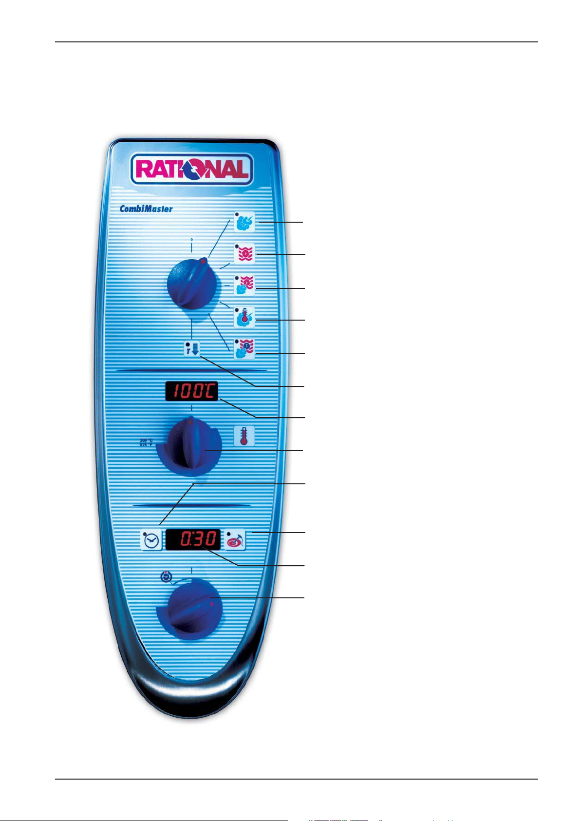
CM Control Panel
Steam (100°C / 212°F)
Hot Air (30°C - 300°C / 86 - 572°F)
Combi Steam (30°C - 300°C / 86 - 572°F)
CM
Low Temp. Steam (30°C - 99°C / 86 - 210°F)
Finishing (30°C - 300°C / 86 - 572°F)
Cool Down
Cabinet temperature display
Cabinet temperature setting
Timer
Gas: Reset key
Core temperature Set-Temp. -control
Timer - Core temperature display
Timer - Core temperature dial
Set-Temp. -control
Edition 10-2008
7
Page 8
CM
S2
B5
F3
CM Technique
M4
M1
B1
F4
B3
S3
B2
Y1
Y2
B1 Thermocouple cabinet
B2 Thermocouple quenching / Steam control
B3 Thermocouple core temperature
B5 Thermocouple steam generator (preheating, 180°C (356°F) max)
F3 Safety temperature limiter steam generator 160°C / 320°F
F4 Safety temperature limiter cabinet 360°C / 680°F
Y1 Solenoid valve lling
Y2 Solenoid valve quenching
M1 Fan motor (without jumper)
M4 Pump SC-Automatic
S2 Level electrode
S3 Door contact switch
CM 201/202 only:
M2 Fan motor top (with jumper)
8
Edition 10-2008
Page 9
CM
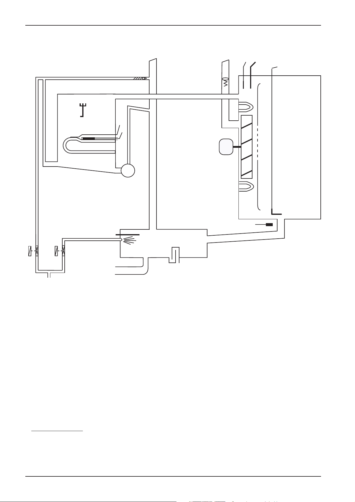
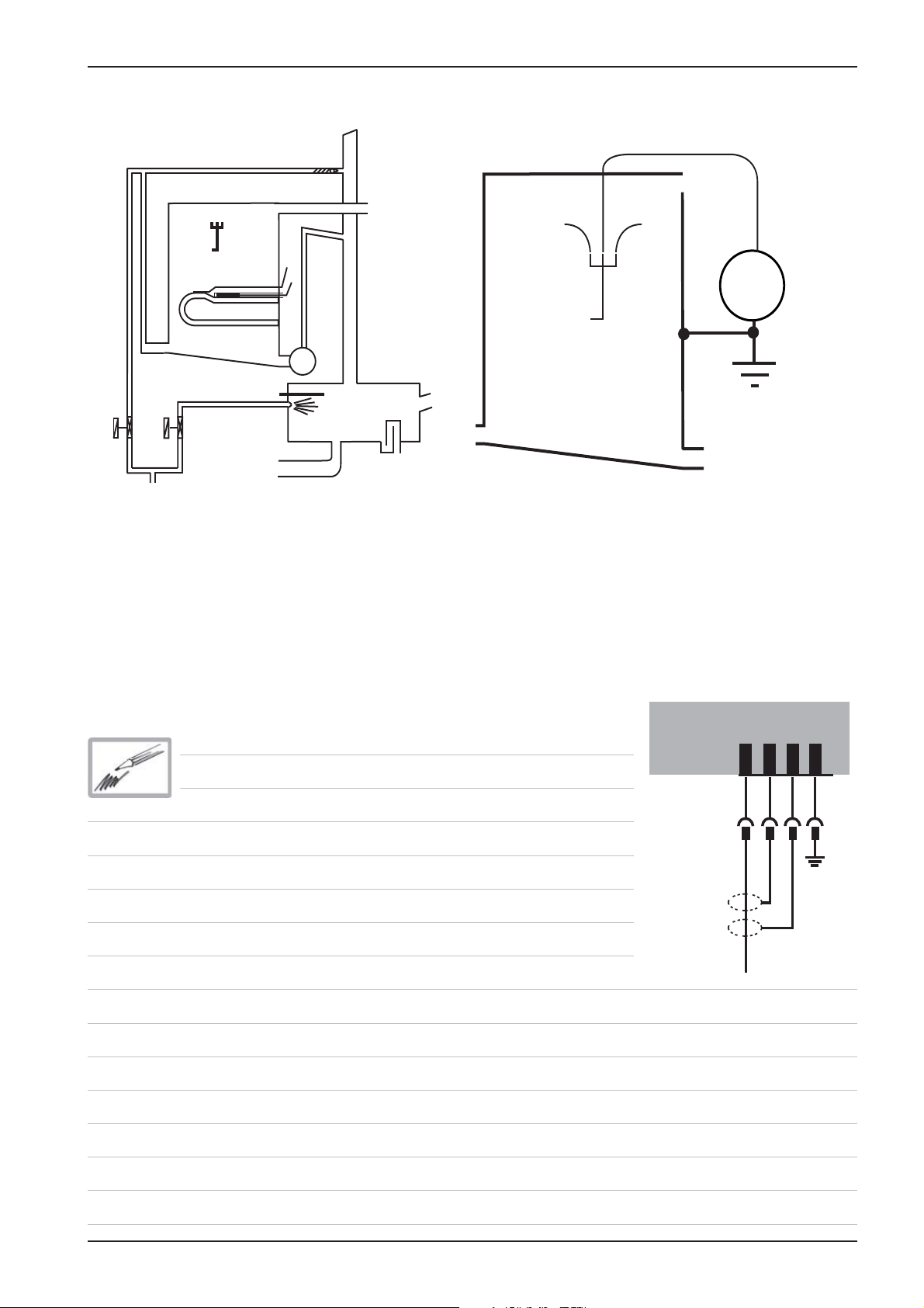
Water level control Steam Generator
S2
B5
F3
S2
M4
B2
V
AC
Y1
Center S2 ==> Ground: 2 - 6V AC: water level too low
steam heating must switch OFF
solenoid valve lling Y1 ON
Center S2 ==> Ground: 0V AC: water level reached
steam heating can switch ON
Every 2 minutes steam elements will switch off for
water level control
Y2
solenoid valve lling Y1 switched OFF
PCB
1 2 3 4
X12
Edition 10-2008
9
Page 10
CM
RATIONAL SC Automatic
During the production of steam, the concentration of minerals inside the steam generator will increase
over time. These minerals settle on the heating elements and heat exchanger as well as the interior
steam generator walls.
In order to reduce this effect the steam generator will be pumped off and ushed regularly depending
on the duration of steam production. This process needs approximately 45 seconds.
After emptying the steam generator it will be lled automatically with fresh water.
There are 4 conditions to start this SC Automatic:
1. Heating time of the steam generator must exceed 60 min.* (SCC Care Control: 120min)
and
2. the temperature of the thermocouple inside steam generator (B5) must be below 65°C (149°F)
and
3. the temperature of the thermocouple inside interior cabinet (B1) must be below 70°C (158°F)
and
4. the unit is switched ON.
* - can be adjusted from 20-120min
In case the unit is used permanently the above mentioned temperature conditions
can not be met.
In this case the following 2 conditions apply:
1. The heating time of the steam generator reaches the twice the set duration*,
i.e. 120 min. and
2. the unit door is open for longer than 30 seconds
After completion of the SC-Automatic the accumulated steam heating time is re-set to zero.
SC-Automatic does not replace the need for descaling and/or installing water treatment lter
10
Edition 10-2008
Page 11
CM
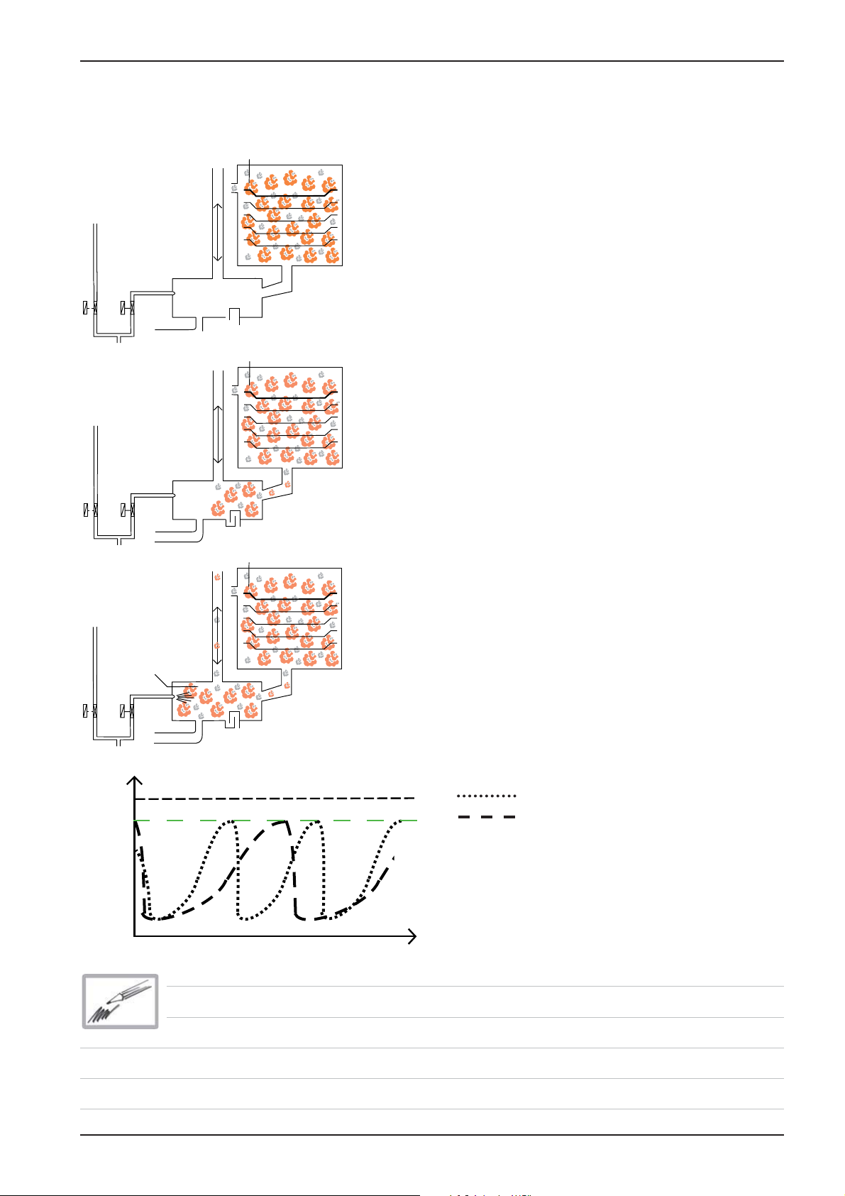
Steam Control CM
Intelligent steam control via quenching sensor
B1
1. Filling of interior cabinet based on time and
temperature control of B2 quenching sensor;
(cabinet if fully lled with steam and all sur-
B2
Y2
Y1
B1
faces have reached steam temperature).
2. After steam saturation inside cabinet steam
will also ll quenching chamber
Y1
Y1
Temp.
70°C
(158°F)
B2
Y2
B1
3. After reaching quenching temperature (B2)
quenching solenoid Y2 will be activated.
Depending on the frequency of temperature
raise of the quenching sensor B2 the duration
B2
Y2
B1 - 100°C(212°F)
of the next steam supply is calculated.
B2 temperature with partial load
B2 temperature with full load
4. The amount of steam inside the cabinet is
directly depending on the temperature variation of quenching sensor B2.
t (s)
Edition 10-2008
11
Page 12
CM
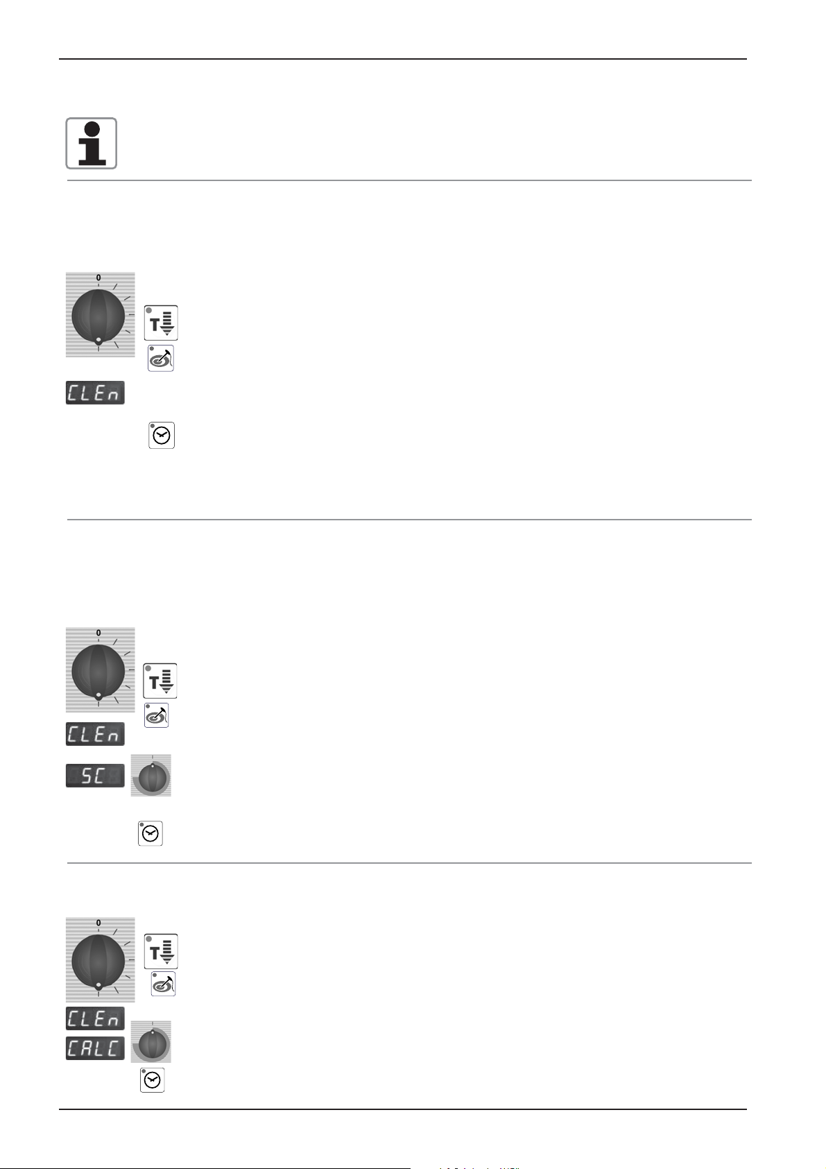
Additional functions CM
Below are listed the additionaly functions for the user / operator:
1. Cleaning program
1) Cool down cabinet below 60°C / 140°F
2) Spray inside cabinet with Rational cleaner
3) Close cabinet door
4) Select „Cool Down
5) Press core temperature key for 10 sec.
6) „CLEn“ will show in cabinet temperature display
7) Press timer key 1x; Cleaning program starts automatically (open cabinet door
and rinse interior cabinet after 40 min.) Close door again. Since Software version C1-06-05 a 10 min step hot air will follow to dry the interior cabinet.
8) After end of program, leave cabinet door open over night.
2. Empty steam generator
This should be done after each installation to verify free drain connection and prior to disconnection
the unit for storage.
1) Open cabinet door
2) Select „Cool Down“
3) Press core temperature key for 10 sec.
4) „CLEn“ will be shown in cabinet temperature display
5) Select „SC“ with temperature dial
6) Close water tap
7) Press timer key 1x and remain on „Cool Down“ position for about 45 sec.
12
3. Descaling program
1) Open cabinet door
2) Select „Cool Down“
3) Press core temperature key for 10 sec.
4) „CLEn“ will be shown in cabinet temperature display
5) Select „CALC“ with temperature dial
6) Press timer key 1x and follow procedure of the decalci cation instruction. (See
user manual CM).
Edition 10-2008
Page 13

Additional functions CM
4. Changing temperature display from °C to °F
1) Select any mode
2) Press timer and core temperature key simultaneously for 10 sec. until Display
changes from °C to °F or vice versa
3) Release both keys
Aborting of descaling program CM:
- Switch unit off and on again
- press core temperature key 1x
- remaining time of 20 minutes will be displayed. During this time the steam generator will be
ushed and the unit will be operated in steam mode for a couple of minutes to eliminate all remaining chemical residues.
CM
Edition 10-2008
13
Page 14
CM
F6.1
2 AT
X16
F6
CM PCB
42.00.004 from 04-2004 ---- 42.00.047 from 02-2006
42.00.004
Transformer
42.00.047
X16
2 AT
F6.1
X63
0,1 AT
F1 F2
X2 B3 Core temperature
2 AT
X3 B1 Interior cabinet
X7
X4 B2 Quenching / Steam control
X19
1
X20
1
X6 B5 Steam generator
X7 ON - OFF switch
X8 Buzzer
2 AT
F6
X7
X19
1
X20
1
X18
X23
1
X12 Level electrode
X 16 power supply from transformer (42.00.047)
X18 SC - pump
X19 Solenoid valves
X20 Energy management system / Sicotronic
X23 Vent hood (signal door open / closed)
X24 SSR
1
2
on
off
3
4
Temperatur
Poti
1
1
Since February 2006 PCB 42.00.004 is replaced by 42.00.047.
(Conversion kit: 87.00.139, pls. see Technical info 04-2006)
The transformer on the new PCB 42.00.047 is no more existing and replaced by
external transformer 40.00.227
X31
X8
X12
X26
X27
RS 485
1
1
X3X4X6
X30
RS 232
X50
X2
1
X32X24
Counting sequence
X26 SSR pulsing (USA version only)
X27 Door contact switch
X30 Serial interface (RS232)
X31 BUS interface
X32 Timer / Core Temp. Potentiometer
X50 external EEPROM
X63 Not used
14
Edition 10-2008
Page 15
Fan motor 40.00.274
CM
LED
Jumper 40.01.581 is used on oor model 201 and 202 for top position motor only!
Jumper is not used on models 61 - 102 with one motor only!
If jumper is not set correctly E12 will be displayed!
Jumper
LED code fan motor SCC and CM from 04/2004
Reason Remedy
1x Motor doesn’t start, no changing
signal from hallsensor
2x Voltage too low on motor pcb Check supply voltage or
Check for motor blockage or change motor.
change motor.
3x Voltage too high on motor pcb Check supply voltage or
change motor.
4x rpm measurement defective Change motor.
5x Motor pcb temperature >105°C Check cooling system (cooling fan, air
intake lter), otherwise change motor
6x Supply voltage <80V Check power supply
(F1-F2)
7x Motor pcb defective Change motor.
8x Motor pcb defective Change motor.
Units 3AC400-480V (without neutral) are equipped with motor 40.00.276 (3-phase supply)
This motor is equipped with a 4 pole plug for the supply voltage.
Edition 10-2008
15
Page 16
CM
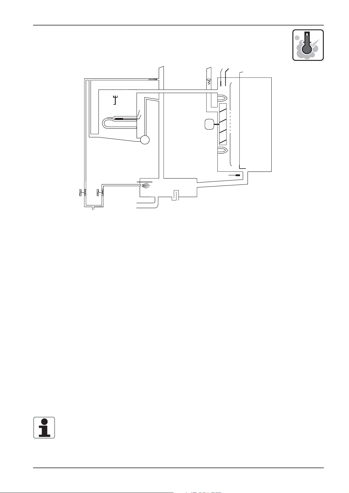
CM - Sequence of events
Mode: Steam 100°C (212°F), Temp. preset, not adjustable
S2
B5
F3
M4
B2
B1
F4
B3
M1
S3
Y2
Y1
Function Step Responsible sensor
1. Select Steam mode
2. Select time or core temperature
3. Close cabinet door Reed switch S3
4. Check water level inside steam generator Level electrode S2 inside Steam Generatorr
5. Time based preheating of steam generator, Thermocouple B5 inside Steam Generator
if B5 is below 85°C (185°F);
6. Timer starts after successful preheating Logic on PCB
(blinking dot in Display)
7. Steam supply up to steam saturation Quenching sensor B2
inside cabinet (Steam control)
8. Hot Air supply (only 50%) when set Cabinet sensor B1
temperature (100°C/212°F) can not be
reached in time by Steam alone
9. Quenching (set to 70°C/158°F) Quenching sensor B2
16
Edition 10-2008
Page 17
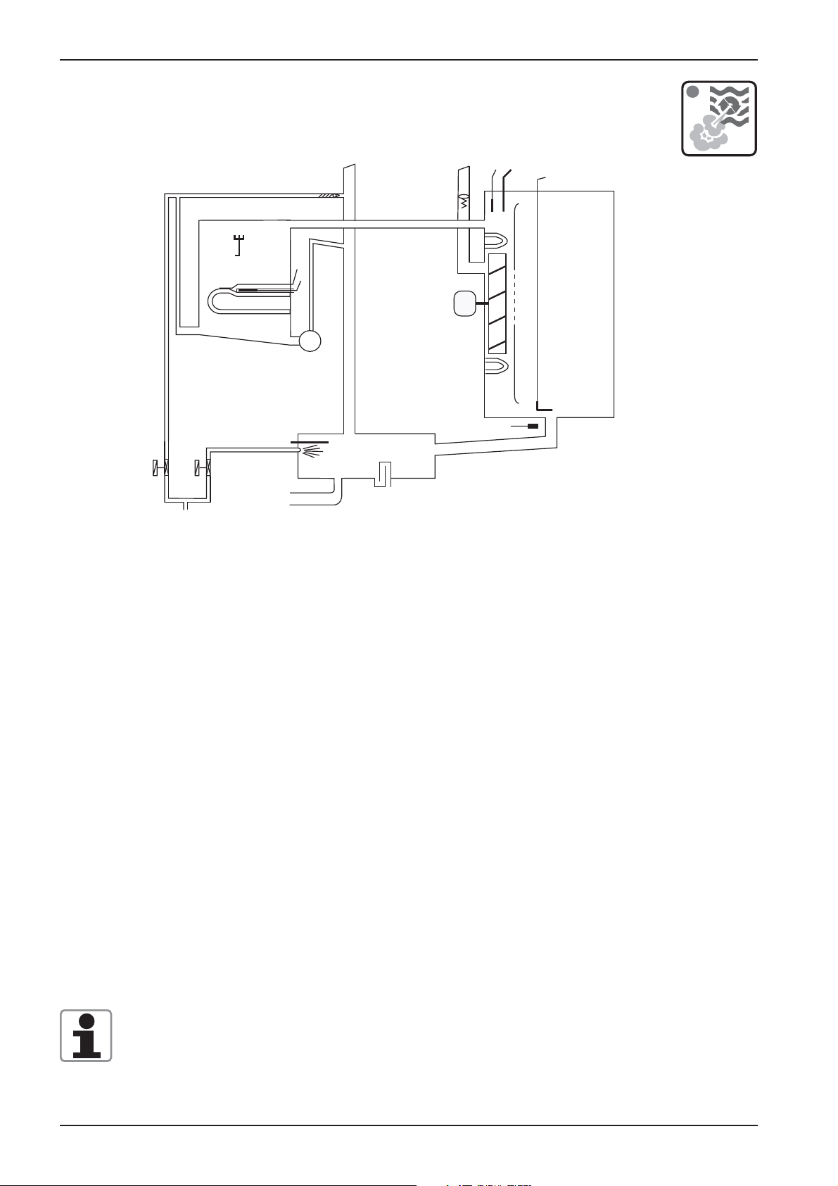
CM - Sequence of events
Mode: Low temperature steam; Temp. range 30-99°C (86-210°F)
B1
F4
S2
B5
F3
M1
M4
S3
B2
CM
B3
Y2
Y1
Function Step Responsible sensor
1. Select Low temperature steam mode
Set temperature 30-99°C (86-210°F)
2. Select time or core temperature
3. Close cabinet door Reed switch S3
4. Check water level inside steam generator Level electrode S2 inside Steam Generatorr
5. Time based preheating of steam generator, Thermocouple B5 inside Steam Generator
if B5 is below 85°C (185°F);
6. Timer starts after successful preheating Logic on PCB
(blinking dot in Display)
7. Steam supply until set temperature Cabinet sensor B1
inside cabinet is reached
8. Hot Air supply (only 50%) when set Cabinet sensor B1
temperature can not be reached in time
by Steam alone
9. Quenching (set to 70°C/158°F) Quenching sensor B2
Note: Reduction of fan motor speed
In case the actual temperature is 2°C / 4°F higher than the set temperature for longer than 2
minutes, the fan speed will be reduced automatically.
Edition 10-2008
17
Page 18
CM
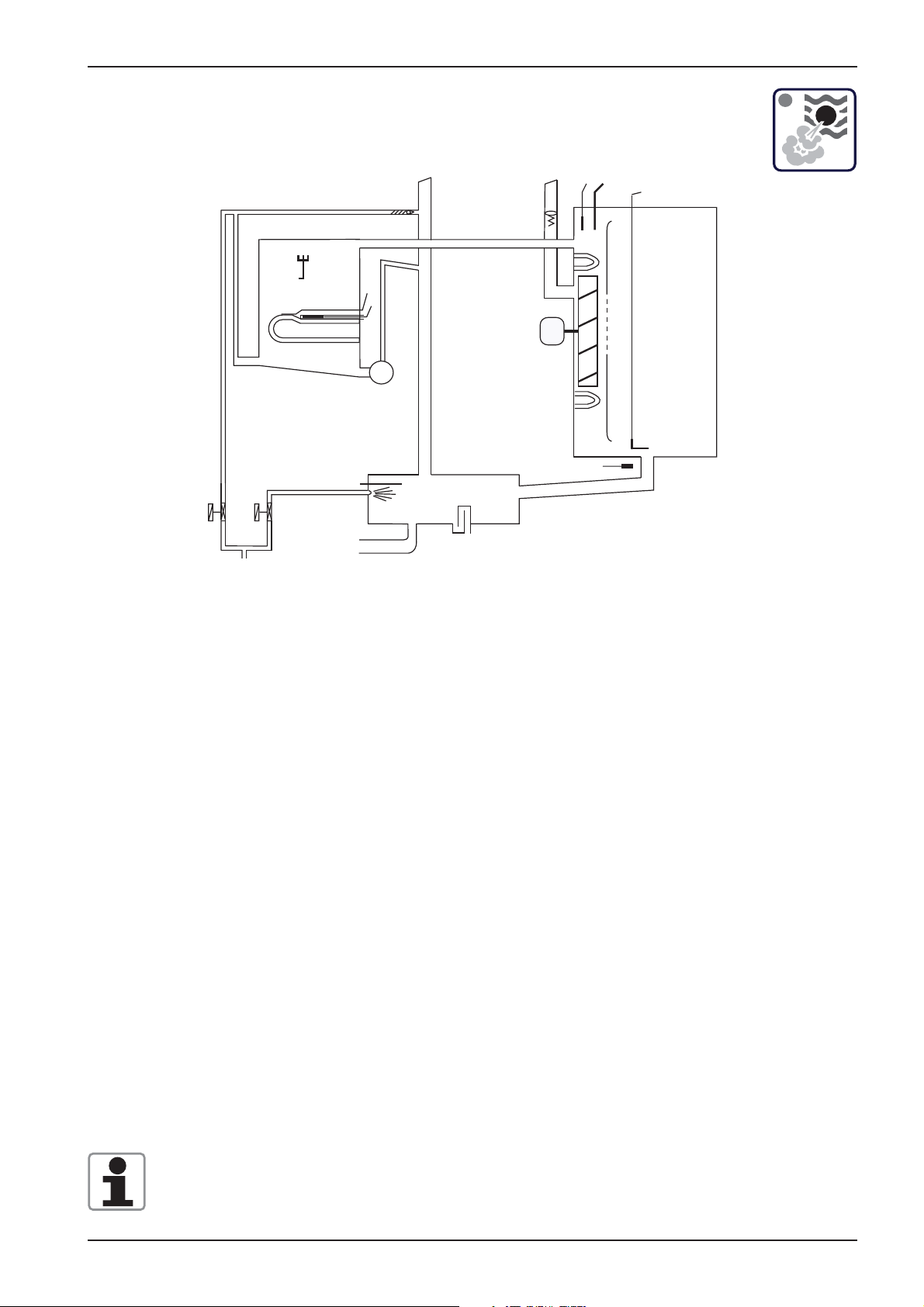
CM - Sequence of events
Mode: Combination; Temp. range 30-300°C (86-572°F)
S2
B5
F3
M1
M4
B2
B1
F4
B3
S3
Y2
Y1
Function Step Responsible sensor
1. Select Combi mode
Set temperature 30-300°C (86-572°F)
2. Select time or core temperature
3. Close cabinet door Reed switch S3
4. Check water level inside steam generator Level electrode S2 inside Steam Generatorr
5. Time based preheating of steam generator, Thermocouple B5 inside Steam Generator
if B5 is below 85°C (185°F);
6. Timer starts after successful preheating Logic on PCB
(blinking dot in Display)
7. Hot Air supply until set temperature Cabinet sensor B1
inside cabinet. Hot air has priority
8. Steam supply up to steam saturation Quenching sensor B2
inside cabinet (Steam Control)
9. Quenching (set to 70°C/158°F) Quenching sensor B2
Note: Reduction of fan motor speed
In case the actual temperature in the range of 30-99°C (86 - 210°F) is 2°C / 4°F higher
than the set temperature for longer than 2 minutes, the fan speed will be reduced automatically.
18
Edition 10-2008
Page 19
F
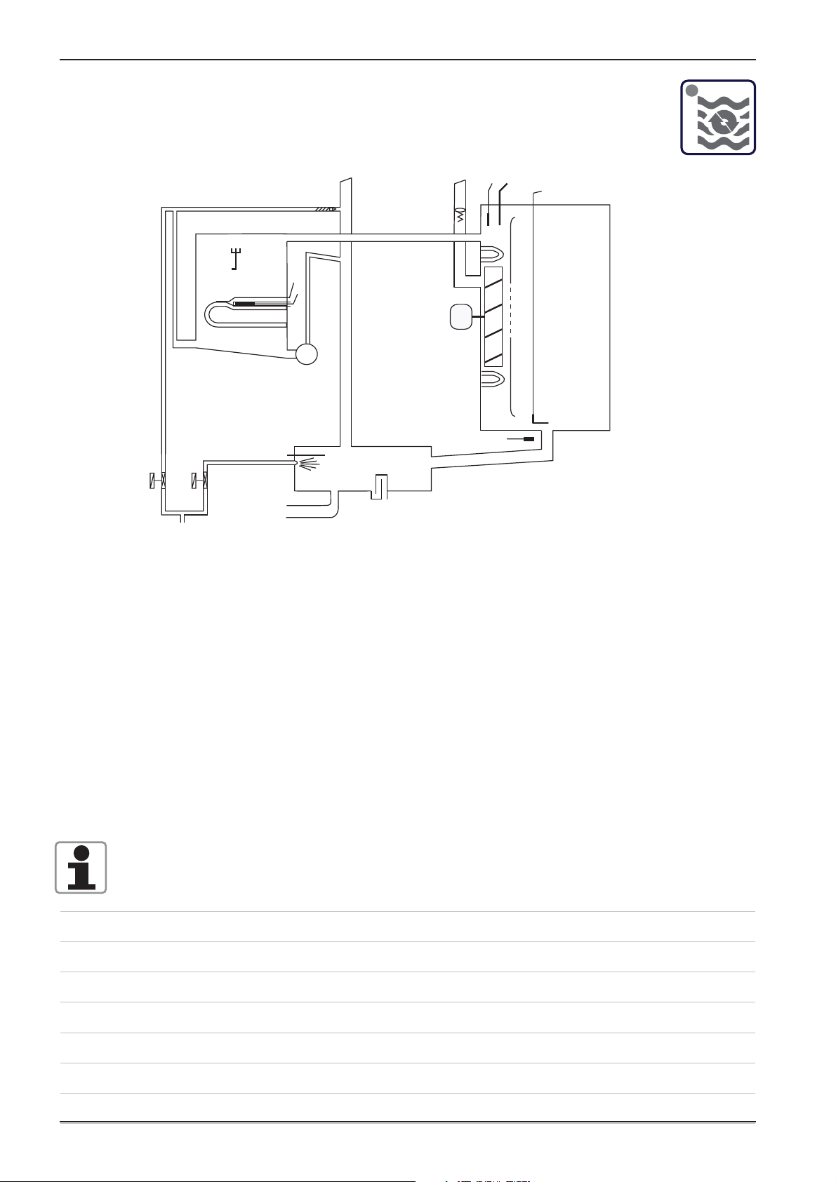
CM - Sequence of events
Mode: Finishing; Temp. range 30-300°C (86-572°F)
S2
B5
F3
M4
B2
CM
B1
F4
B3
M1
S3
Y1
Y2
Function Step Responsible sensor
1. Select Finishing mode
Recommended temperature
30-300°C (86-572°F)
2. Select time or core temperature
3. Close cabinet door Reed switch S3
4. Check water level inside steam generator Level electrode S2 inside Steam Generator
5. Time based preheating of steam generator, Thermocouple B5 inside Steam Generator
if B5 is below 85°C (185°F);
6. Timer starts after successful preheating Logic on PCB
(blinking dot in Display)
7a. Electric units: alternating
12 sec. Hot Air Cabinet sensor B1
6 sec. Steam Quenching sensor B2
7b Gas units: alternating
30 sec. Hot Air Cabinet sensor B1
15 sec. Steam Quenching sensor B2
8. Quenching (set to 70°C/158°F) Quenching sensor B2
Note: Reduction of fan motor speed
In case the actual temperature in the range of 30-99°C (86 - 210°F) is 2°C / 4°F higher
than the set temperature for longer than 2 minutes, the fan speed will be reduced automati-
cally.
Edition 10-2008
19
Page 20
CM
CM - Sequence of events
Mode: Hot Air; Temp. range 30-300°C (86-572°F)
S2
B5
F3
M4
B2
B1
F4
B3
M1
S3
Y2
Y1
Function Step Responsible sensor
1. Select Hot Air mode
Set temperature 30-300°C (86-572°F)
2. Select time or core temperature
3. Close cabinet door Reed switch S3
4. Timer starts immediately Logic on PCB
5. Hot Air supply unitl set temperature Cabinet sensor B1
is reached
6. Quenching (set to 90°C/194°F) Quenching sensor B2
Note: Reduction of fan motor speed
In case the actual temperature in the range of 30-99°C (86-210°F) is 2°C / 4°F higher than
the set temperature for longer than 2 minutes, the fan speed will be reduced automatically.
20
Edition 10-2008
Page 21
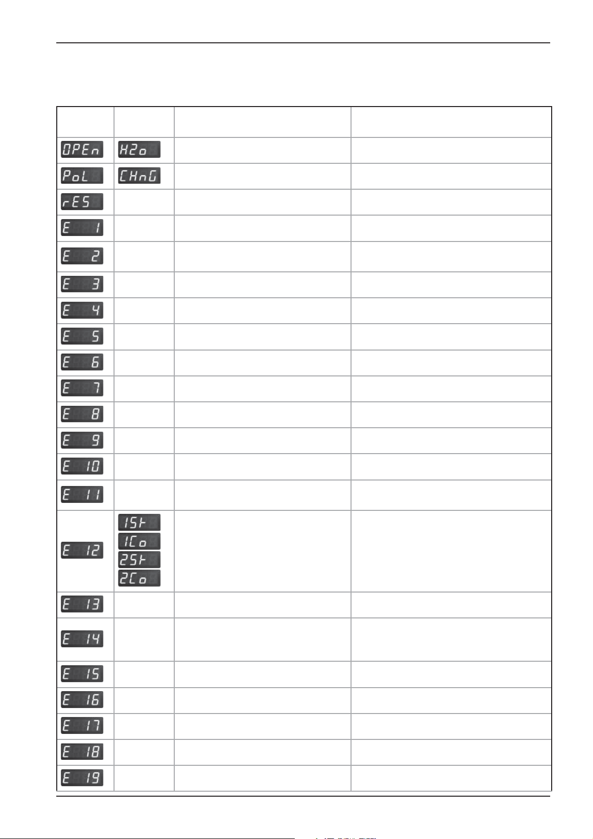
Failure Codes CM
The following error codes are shown to the operator:
For showing information of the cabinet display press core temperature key
CM
Time
display
Cabinet
display
Failure explanation Description / remedy
H2O open Lack of water / open water tap
Change Polarity Phase / Neutral (only gas units)
Reset Gas Flame detection after ignition faulty
external EEPROM Not initialised
Timeout of external
power optimising system
B1 Interior cabinet sensor Sensor broken
B2 Quenching sensor Sensor broken
B3 Core sensor Sensor broken
B5 Sensor steam generator Sensor broken
Thermocouple on PCB Sensor broken
Heating blocked by the extern. energyoptimising system for longer 2 min.
Poti interior cabinet Defective
Poti timer/core temperature Defective
external EEPROM Defective
Mode switch
Fan motor 1 (bottom)
Fan motor 1 (bottom)
Fan motor 2 (top)
Fan motor 2 (top)
M4 SC-pump Mal function
Solenoid valve lling Y1
(failure can only occur during the
descaling program)
PCB temperature above 85°C (185°F)
Steam generator Temperature B5 above 180°C (356°F)
After 5 sec switching on the unit, a
cooking mode couldn‘t be identi ed
St = Status (probably Motor defect)
Co = Communication, (Bus failure)
Mal function
Steam generator Temperature B5 below -5°C (23°F)
Interior cabinet temp. Temperature B1 above 340°C (644°F)
Free
Edition 10-2008
21
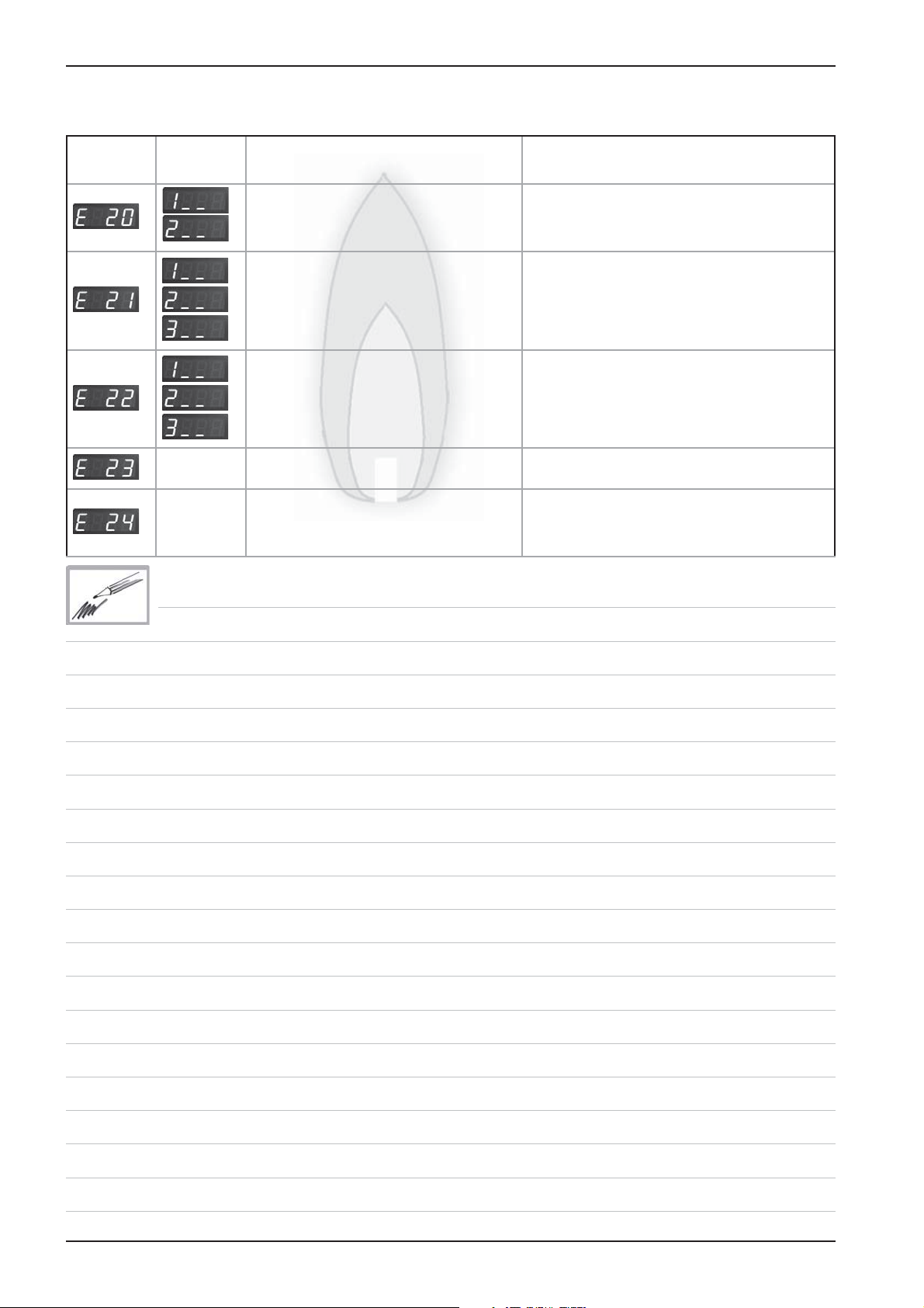
Page 22
CM
Failure Codes CM (cont.)
For showing information of the cabinet display press core temperature key
Time
display
Cabinet
display
Failure explanation Description / remedy
Ignition box 1
Ignition box 2 Ignition box does not reply, Bus failure
Ignition box 1 Steam
Ignition box 1 Hot air
Ignition box 2 Hot air
Ignition box 1 Steam
Ignition box 1 Hot air
Ignition box 2 Hot air
Free
EEPROM
Ignition box defective (change box)
Testing of ignition and monitoring
necessary
Actual data structure of the EEPROM
does not match with the software; flash
pcb first
22
Edition 10-2008
Page 23
CM
F6.1
2 AT
X16
F6
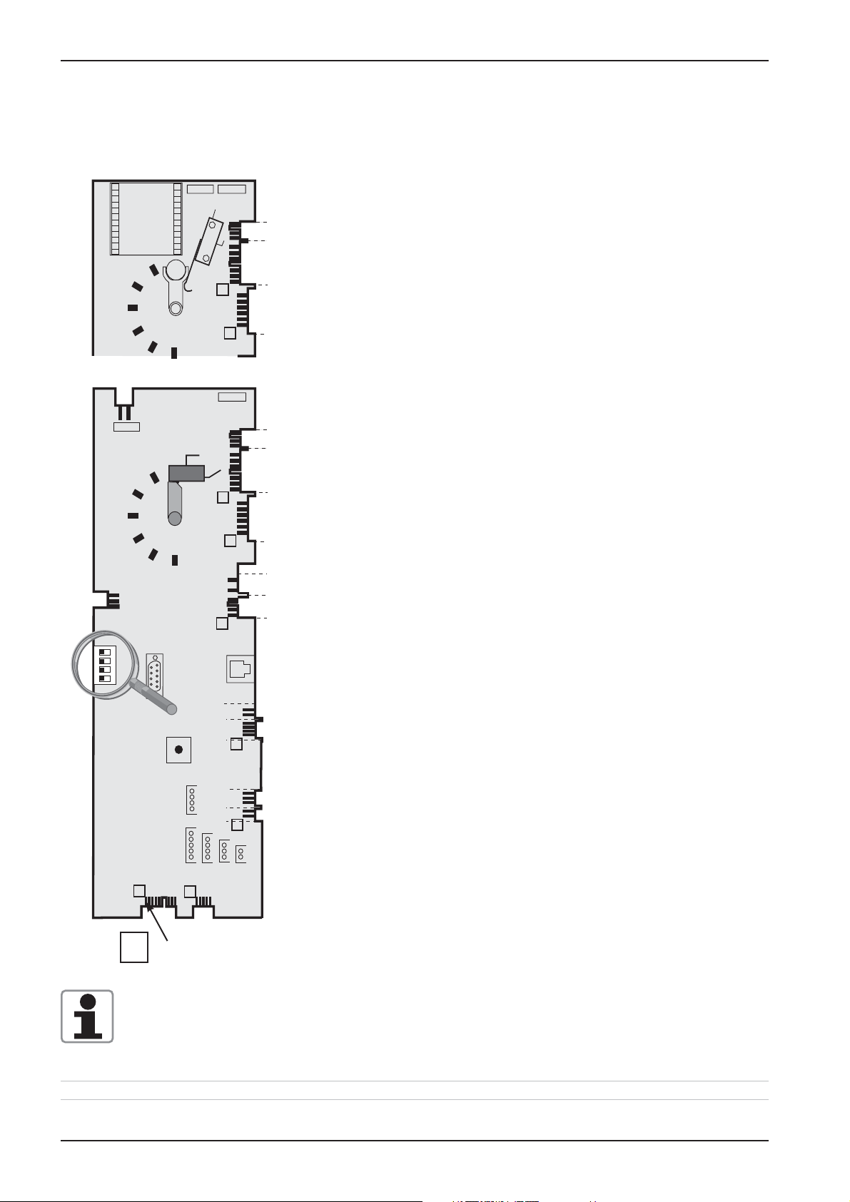
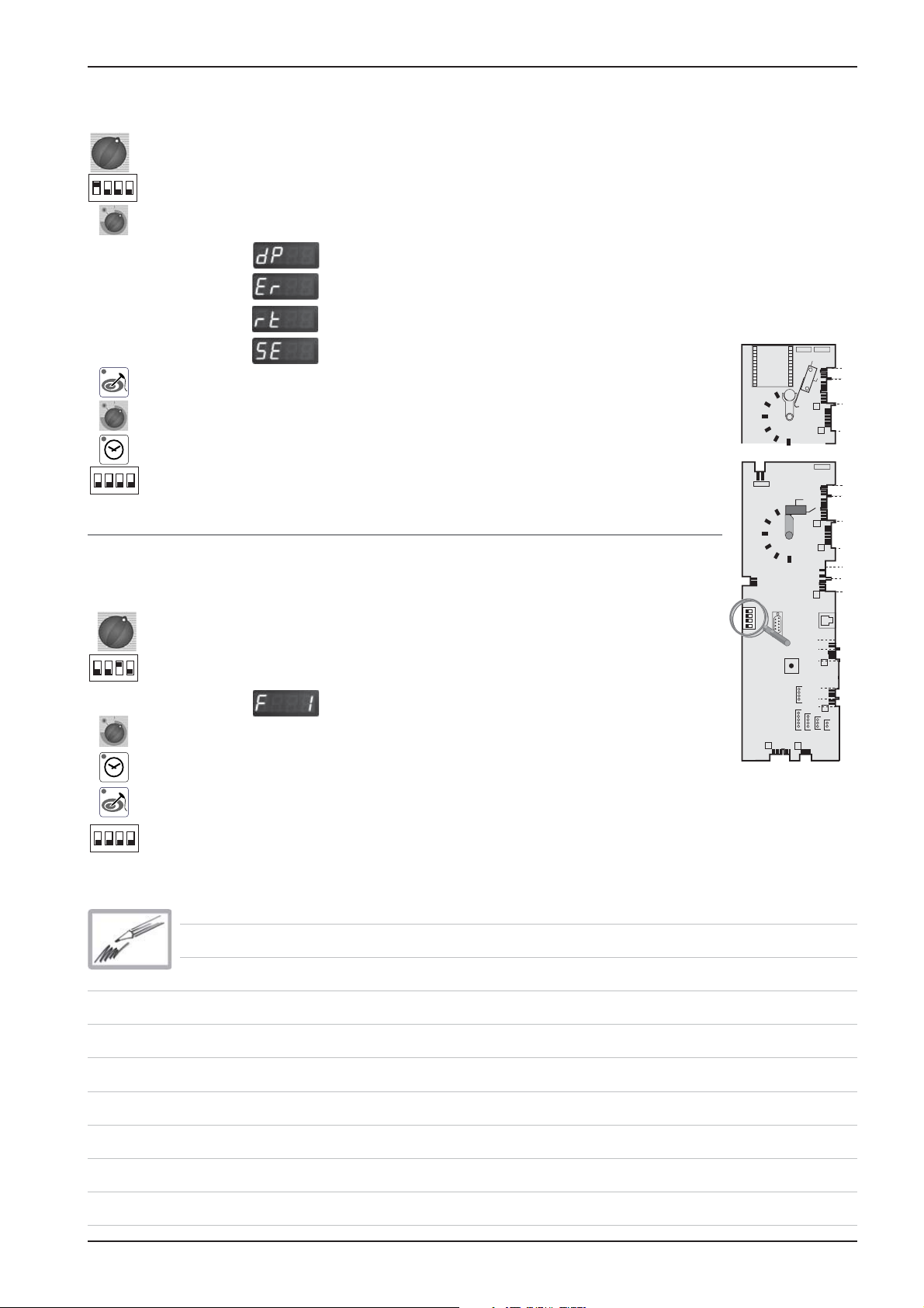
Service level CM
1) Switch unit ON
on
234
1
on
234
1
on
234
1
2) On operator PCB set DIP switch 1 to „ON“ position
3) Select service package with timer dial:
Diagnostic Program
Error code history
Running times
Basic settings
4)
Activate with core temperature key the desired service package
5) Select with timer dial the desired step
6) Activate selected step by pressing timer key
7)
To de-activate service package set DIP switch 1 to „OFF“ position
Function Test
.
X63
1
2
off
3
4
1) Switch unit ON
2) On operator PCB set DIP switch 3 to „ON“ position
First step of function test is displayed.
3) Select desired step of function test with timer dial
42.00.004
Transformer
42.00.047
X16
2 AT
F6.1
on
X30
RS 232
1
0,1 AT
X50
X2
1
F1 F2
1
X32X24
2 AT
X7
X19
1
X20
1
2 AT
F6
X7
X19
1
X20
1
X18
X23
X31
RS 485
X8
X12
1
X26
X27
1
X3X4X6
4) Activate preselected step by pressing timer key
5) Activate selected function step with core temperature key
on
234
1
6)
To de-activate function test set DIP switch 3 to „OFF“ position
.
Edition 10-2008
23
Page 24
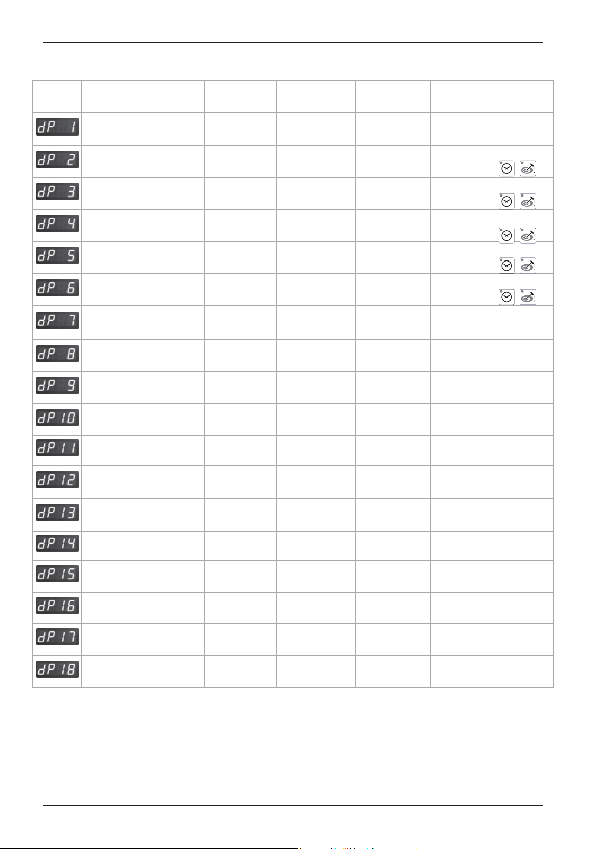
CM
Service level: dP -- Diagnostic Program
Description Connection
Software Version
B1 Cabinet sensor X 3 actual value max value
B2 Quenching sensor X 4 actual value max value
B3 Core sensor X 2 actual value max value
B5 Steam generator
sensor
PCB temperature actual value max value
S3 Door contact X27:(1-2) 1 - 0
S2 Water level steam
generator
Steam elements
0 - off; 1 - 50%; 2 - 100%
X 6 actual value max value
X12:(1-4) S2
X19:(1-3) Y1
Cabinet
Display
Software
Version: C - 1
S2: 0 - 1 Y1: 1 - 0
actual Temp.
B5
Time display
Software
07.01
0 - 1 - 2
Reset by pressing
for 5 sec.
Reset by pressing
for 5 sec.
Reset by pressing
for 5 sec.
Reset by pressing
for 5 sec.
Reset by pressing
for 5 sec.
0 = door open
1 = door closed
+
+
+
+
+
Hot Air elements
0 - off; 1 - 50%; 2 - 100%
Speed fan motor bottom BUS Set rpm actual rpm
Speed fan motor top BUS Set rpm actual rpm
Energy management
(Sicotronic)
SSR control (US version)
Unit size and type
Flame current Steam x.x A*
Flame current Hot air
top
Flame current Hot air
bottom
X 20 1 - 0
X24
actual Temp.
B1
61 - 202 ELE - GAS
0 - 1 - 2
1 - 0 0 = US version only
Hot air top
x.x A*
Hot air bottom
x.x A*
only oor model
201/202
since SW Version:
C1-06-05 ( ame current)
since SW Version:
C1-06-05 ( ame current)
since SW Version:
C1-06-05 ( ame current)
With SW Version C1-06-05 the ame current will show as 20-24A
*
(This value must be divided by 4 to get the correct ame current e. g. 22:4 = 5,5A.)
Starting with SW version C1-07-01 the actual ame current is shown .
24
Edition 10-2008
Page 25

CM
Service Level: ER -- Error code history
Since software version C1-07-01 the last 10 general error messages are shown
(applies for electric and gas models)
Er When timer key is pressed the error code will be displayed. i.e.:
Error number Error Code Description
Er1 3 B1 Cabinet sensor defective
Er2 14 Y1 Filling solenoid defective
Er3 ---- ER10
Gas error GE: (gas units only!)
Since software version C1-07-01 the last 16 gas error messages (GE11 - GE26) are shown in
addition to the general error messages. These error codes are generated by the ignition box
Error number Error Code Description
GE11 20 No rpm signal
GE12 32 No ame after 5 ignition sequences
GE13 --- GE26
Indication of ignition box error messages (1-32 is shown to the operator as „rES“):
1 Hot air or Steam no gas, gas valve or electrode defective
14 Hot air gas valve control, change ignition box
19 Hot air no ame because ame current is too low
check burner setting, ame current, ignition cable and plug
20 Hot air wrong or no rpm signal from gas blower
check gas blower, power supply gas blower and control harness of gas blower
22 Hot air no ame after 5 ignition sequences
no gas, gas valve or electrode defective
24 Steam gas valve control, change ignition box
29 Steam no ame because ame current is too low
check burner setting, ame current, ignition cable and plug
30 Steam wrong or no rpm signal from gas blower
check gas blower, power supply gas blower and control harness of gas blower
32 Steam no ame after 5 ignition sequences
no gas, gas valve or electrode defective
Possible failure in case of „E21“
33, 36 Change ignition box
35 Check frequency of main
39 Hot air Check burner setting, ignition electrode and distance, and ame current
40 Hot air Check ignition cable
42 Steam Check burner setting, ignition electrode and distance, and ame current
43 Steam Check ignition cable
Is shown on display „CHnG PoL“
34 Change polarity of mains
All other numbers (2-13, 15-18, 21, 23, 25-28, 31): change ignition box
Edition 10-2008
25
Page 26
CM
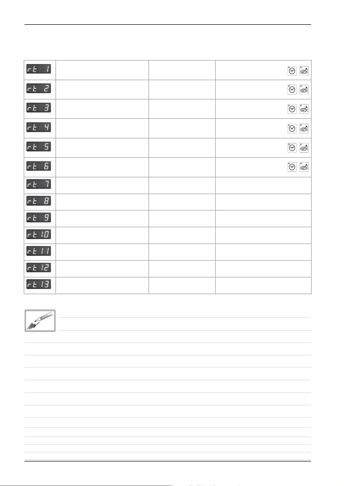
Service Level: rt -- Running Time
Description Timer display: 1-999
Temp. display: >1000
Comment
Total S3 door openings number
Total time Y1 valve lling min
Total time Y2 valve quenching min
Total time M4 SC-pump min
Total time steam heating time hrs
Total time hot air heating time hrs
Total time steam mode hrs Can not be reset
Total time hot air mode hrs Can not be reset
Total time combination mode hrs Can not be reset
Reset by pressing
for 5 sec.
Reset by pressing
for 5 sec.
Reset by pressing
for 5 sec.
Reset by pressing
for 5 sec.
Reset by pressing
for 5 sec.
Reset by pressing
for 5 sec.
+
+
+
+
+
+
Total time vario steam mode hrs Can not be reset
Total time nishing mode hrs Can not be reset
Total time cleaning program hrs Can not be reset
Total running time unit hrs Can not be reset
26
Edition 10-2008
Page 27
+
+
CM
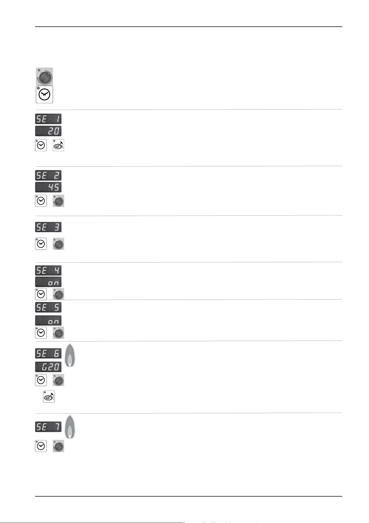
Service level: SE -- Basic settings
Switch unit OFF and ON again after any changes made!
Select desired step with timer dial
(fan motor and heating elements are automatically OFF)
Activate selected step with timer key
Steam heating time since last SC-Automatic
Press time and core key simultaneously for 5 seconds to set steam heating time
(SE2) to preset steam heating time plus 1 minute (default 45+1min) => test function
for SC-Automatic
Preset Steam heating time until SC-Automatic (default 60min)
Press time key and adjust preset steam heating time from 20 - 120 minutes with timer
dial
+
+
+
+
Flushing time SC-Automatik (default 45 seconds)
Press time key and adjust ushing time of SC-Automatik from 30 - 90 seconds with
timer dial
Operation SC pump (oFF - continuous or on - pulsing)
Press time key and select „on“ or „oFF“ with timer dial
Show mode (on - oFF) SHO
Press time key and select „on“ or „oFF“ with timer dial
Setting new gas type (G20, G25, G30, G31, 13A)
Press time key, keep it pressed and select new gas type with timer dial
Con rm new gas type by pressing core temperature key once.
Corresponding gas blower speed is automatically adjusted
NOTE: After changing gas type a waste gas analysis must be carried out in the function test.
+
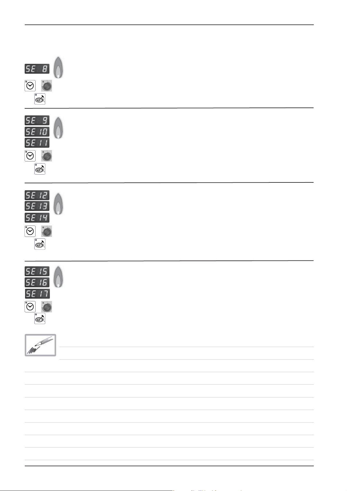
Presetting of CO2 screw in mm on gas valve after gas type modi cation / changing
gas valve
Press time key, keep it pressed and select with timer dial “ST“ for steam, “HA1“ for
hot air top or “HA2“ for hot air bottom (only 201/202) with timer dial;
Average lenght in mm of CO
screw on gas valve is shown on timer display
2
Edition 10-2008
27
Page 28
CM
Service level: SE -- Basic settings
Adjustment of installation altitude above sea level (since SW C1-06-05) -
500m - 4500m
+
+
+
Press time key, keep it pressed and select installaton altitude in 500m steps by timer
dial. Con rm altitude setting by pressing simultaneously core temperature key once
Adjusting speed of blower motor steam (+/ -10%)
(After blower speed adjustment the original rpm is shown in the temp. display, the
changed rpm is shown in the time display)
Press time key, keep it pressed and adjust displayed rpm with timer dial
SE9 = MIN rpm; SE10 = Start rpm; SE11 = MAX rpm
NOTE: After changing speed of blower motor a waste gas analysis MUST be carried
out in the function test.
Adjusting speed of blower motor hot air top (+/ -10%)
(After blower speed adjustment the original rpm is shown in the temp. display, the
changed rpm is shown in the time display)
Press time key, keep it pressed and adjust displayed rpm with timer dial
SE12 = MIN rpm; SE13 = Start rpm; SE14 = MAX rpm
NOTE: After changing speed of blower motor a waste gas analysis MUST be carried
out in the function test.
Adjusting speed of blower motor hot air bottom (+/ -10%)
(After blower speed adjustment the original rpm is shown in the temp. display, the
changed rpm is shown in the time display)
Press time key, keep it pressed and adjust displayed rpm with timer dial
+
SE15 = MIN rpm; SE16 = Start rpm; SE17 = MAX rpm
NOTE: After changing speed of blower motor a waste gas analysis MUST be carried
out in the function test.
28
Edition 10-2008
Page 29
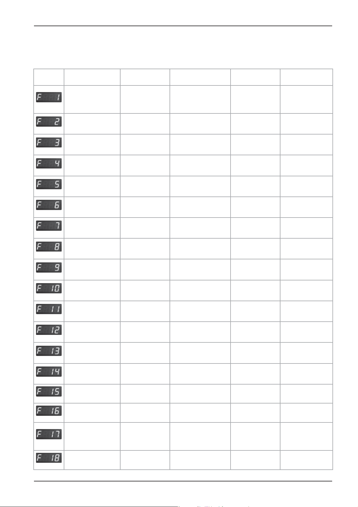
Service level: F -- Function test
NOTE: In Function test components are NOT protected against overload!
Set DIP switch 3 to „ON“ position!
CM
Function Connection
PCB
Steam 50%,
Electric unit X24:(1-2)
Steam 100%
Electric unit
Hot air 50%
Electric unit
Hot air 100%
Electric unit
Steam Gas unit BUS
Hot air top
Gas unit
Hot air bottom
Gas unit
Bottom Motor MAX
rpm
X24:(1-2)+(5-6)
X24:(7-8)
X24:(7-8)+(3-4)
BUS
BUS
BUS Set rpm Act. rpm
Cabinet
display
actual temp.B5
steam generator
actual temp.B5
steam generator
actual temp.B1
cabinet
actual temp.B1
cabinet
actual temp.B5
B5 Dampfgenerator
actual temp.B1
cabinet
actual temp.B1
cabinet
Time
display
1 / 0
1 / 0
1 / 0
1 / 0
1 / 0
1 / 0
1 / 0
Comment
Gas:
no function
Gas:
no function
Gas:
no function
Gas:
no function
Electric:
no function
Electric:
no function
Electric:
no function
Bottom Motor MIN
rpm
Top Motor
MAX rpm
Top Motor
MIN rpm
Solenoid valve
quenching
Solenoid valve
lling
SC Pump
Buzzer X8:(1-2) 1 / 0
All Displays / LED
Relais Ultravent
(door open
/ close)
BUS Set rpm Act. rpm
BUS Set rpm Act. rpm
BUS Set rpm Act. rpm
X19:(2-4)
X19:(1-3) Level electrode
X18:(1-2) M4
X12:(1-4) S2
X 23: (1-2-3) 1 / 0
actual temp.
B2 quenching
S2, 1 / 0
Level electrode
S2, 1 / 0
Y2
1 / 0
Y1
1 / 0
M4
1 / 0
only existing with
connected UV
no function
Edition 10-2008
29
Page 30
CM
Service Level: F -- Function Test
Note: In function test components are NOT protected against overload!
Set DIP switch 3 to „ON“ position!
Function Connection
I/O pcb
Gas blower Steam
MIN rpm
Gas blower Steam
Start rpm
Gas blower Steam
MAX rpm
Gas blower Hot air top
MIN rpm
Gas blower Hot air top
Start rpm
Gas blower Hot air top
MAX rpm
Gas blower Hot air bottom
MIN rpm
Gas blower Hot air bottom
Start rpm
BUS actual rpm Set CO
BUS actual rpm
BUS actual rpm Set CO
BUS actual rpm Set CO
BUS actual rpm
BUS actual rpm Set CO
BUS actual rpm Set CO
BUS actual rpm
Cabinet
display
Time
Display
Comment
Check CO2 value
2
Adjust CO2 value with
2
2
2
2
screw
CO
2
Check CO2 value
Adjust CO2 value with
screw
CO
2
Check CO2 value
Gas blower Hot air bottom
MAX rpm
BUS actual rpm Set CO
Adjust CO2 value with
2
CO
screw
2
30
Edition 10-2008
Page 31

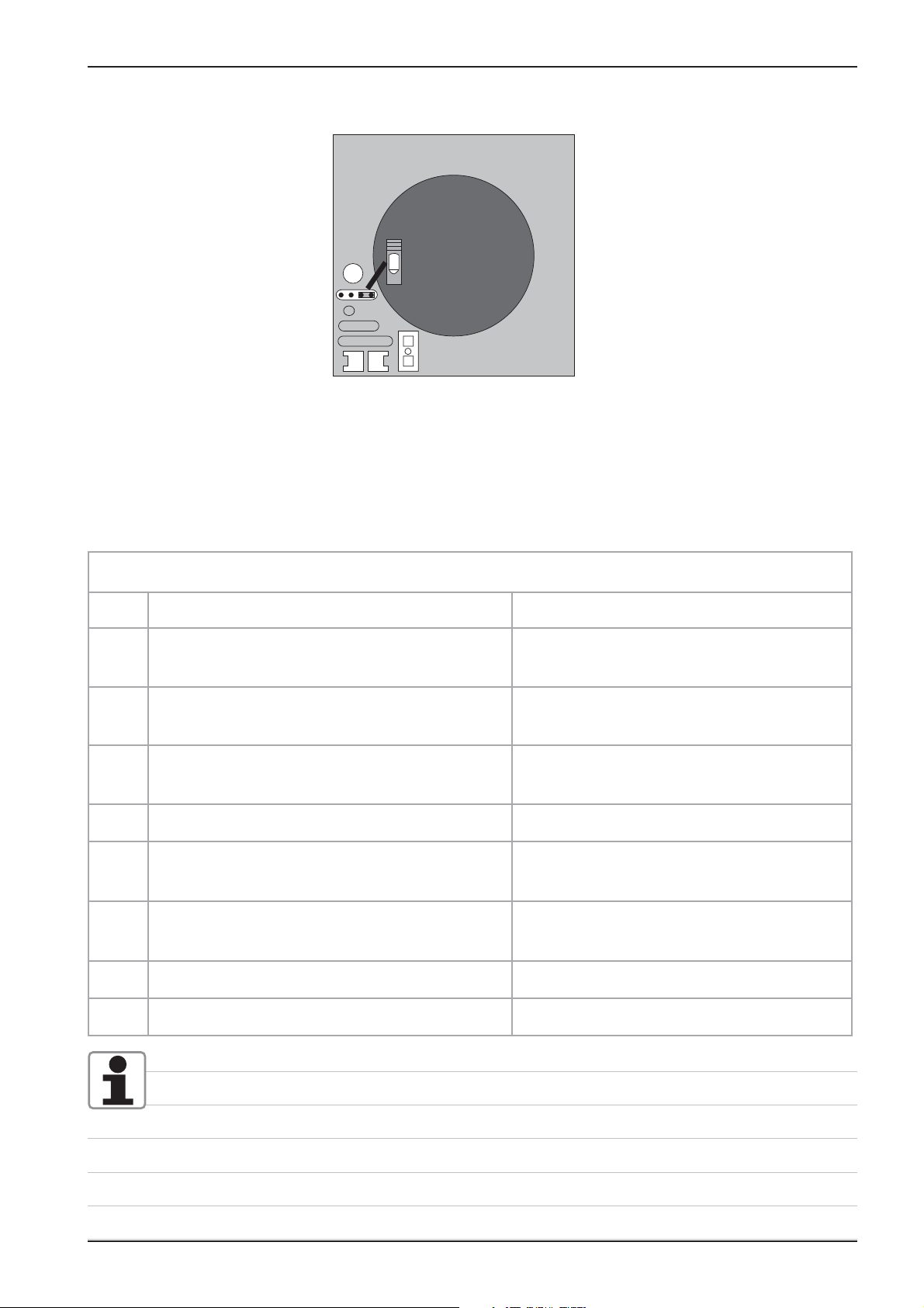
Software update CM units
1 General
To update a CM unit of new generation you need:
- CM-Software e.g. C-1-07.01.hex
- software „Megaload.zip“.
Both are available on the Rational Service internet page under:
„Technical documentation/Software update SCC-Line/CM“.
- download CM-Software e.g.“C-1-07.01.hex“
- download „megaload.zip“ to PC,
- open le„megaload.zip“,
- Start the program Setup.exe and follow the description on the screen,
- Start the program Megaload and carry out basic settings.
Open CM Software; e.g.: C-1-07.01.hex
Select desired interface on the PC, e.g. Com1
Transfer rate must be set to 19200 bps.
On the „Message“ window the progress of the download
software download is indicated.
CM
Now You can load the software:
- direct from PC to CM unit, (see item 4 next page) or
- with Flash-Box 87.00.037 to CM unit, (see following items 2, 3).
2
Load software to Flash-Box
Flash-Box kit contains of:
- Flash-Box
- Adapter cable RS 232
and USB-cable
(only required for down
loading the unit software to the Flash-Box).
- Connect RS 232 adapter cable to Flash-Box and to the selected interface (e. g. COM 1) of the PC.
- Connect USB-cable to Flash-Box and PC.
- After the USB cable was connected the les which are transferred will appear on the Message
window. An end sign indicates that the transfer is completed.
- Open lid of the
Flash-Box
- Set DIP - switch
2 to „ON“. (other
switches remain in
the „OFF“ position)
- On the Flash-Box set DIP- switch 2 to „OFF“ and 3 to „ON“ (the other switches remain „OFF“).
Flash-Box is ready for use.
Edition 10-2008
31
Page 32

CM
1
2
3
4
on
X7
X19
X20
X18
X23
X31
RS 485
X8
X12
X16
X17
X26
X27
3X32
X24
X63
F6.1
F6
X3X4XX6
X2
X50
on
off
0,1 AT
2 AT
X7
X19
X20
F2
0,1 AT
2 AT
Transformer
X16
X30
RS 232
3 Copy software from ash box to unit:
- Switch off unit with mode switch and open control panel;
- Connect RS 232 interface of CM pcb with ash box;
- Switch CM unit on. Displays of pcb remain off. Green LED of ash box starts
blinking.
- After successful uploading the CM pcb will switch on; the green LED on the
ash box stops blinking and remains on continuously.
- Switch unit off and disconnect ash box.
- Unit is ready for operation;
4 Load software via PC to CM unit:
- Switch off unit with mopde switch and open control panel
- Connect RS 232 interface of CM pcb with standard RS 232 cable to PC.
- Switch CM unit on. Displays of pcb remain off. The transfer status will be
displayed in a message window.
42.00.004
2 AT
0,1 AT
F1F1F2
Transformer
RS 232
42.00.047
X16
X7
0,1 AT
X19
F6.1
X20
X63
on
on
off
X30
RS 232
X50
X2
X
X24
- After successful uploading the CM pcb will switch on;
- Switch unit off;
- Close megaload program and disconnect RS 232 cable.
- Unit is ready for operation;
To connect via USB adapter the driver must be installed on the PC.
Set driver with the following setting:
Bit: 9600
Data bit: none
Parity: 8
Stop bit: none
Flow control: none
Connect USB cable with ash box and PC
Start Megaloader
Connect null modem cable with ash box and USB Adapter
After connecting the USB cable the download is shown in the display window.
32
Edition 10-2008
Page 33

Fault tree: Changing CM pcb / replace EEPROM
2 reasons to follow below procedure:
- Changing of pcb (software version on replacement pcb is not known)
- Unit display „E1“ - replace external memory with new EEPROM
Disconnect unit from power supply
(Remove fuses F1 and F2)
Replace new PCB
Note:
Do NOT connect external EEPROM as software version of pcb might
not be compatible with pcb without updating!
CM
Reconnect unit from power supply
( x fuses F1 and F2 back)
Software update of pcb to
C1-07-01 or later
Disconnect unit from power supply
(Remove fuses F1 and F2)
Reconnect EEPROM to pcb
Reconnect unit from power supply
( x fuses F1 and F2 back)
Error „E1“ still existing
Call Rational Service
Edition 10-2008
OK
33
Page 34

CM
34
Edition 10-2008
Page 35

SCC Control panel
SCC
Edition 10-2008a
35
Page 36

SCC
1
2
3
4
1
2
3
4
Comparing display of software version
Display up to software version
SCC 01-07-12
Display since software version
SCC 02-01-01
13:45
36
Edition 10-2008a
Page 37

1
2
3
4
1
2
3
4
1
2
3
4
Display since software version SCC 02-01-01
SCC
SelfCooking Control
Level 1
13:45
Large roast
SelfCooking Control
Level 2
roast braise
roast with
crackling
overnight
roasting
13:45
roasting
soft cooking
Back to previous level
soft
SelfCooking Control
Level 3
overnight
roasting
low
medium
close
door
62°C
high
Pan fries
CleanJet, HACCP, Delta T, E1/2
Start time, CDS, Descaling, Settings
Poultry
Selection of core temperature
Fish
Help: guide line for selected setting;
Side dishes
practical hints for product to be used in the
respective SCC cooking process
Potato product
Store selected setting
Egg dishes/Desserts
Searing
Bakery products
Finishing
Edition 10-2008a
37
Page 38

SCC
1
2
3
4
1
2
3
4
1
2
3
4
Display since software version SCC 02-01-01 to 03-01-05
Combi Steamer mode
0% 10% 20% 30% 40% 50% 60% 70% 80% 90% 100%
200°C
continous
Function level
CleanJet
E
CleanJet
Setting of humidity
Setting of cabinet temperature
Setting of time
Setting of core temperature
Moistening
Setting of fan speed (lowest level=intermittent)
Cool Down
Function level no link on I/O X20
E
No 230V on I/O X21
CleanJet programs
Delta -T cooking - 1/2 Energy
Telephone Chef-Line, delete all programs,
program lock, buzzer setting, time setting
Start time
Start time
setting start time
Download and upload of unit data like customer
programs, HACCP and service data
Service level
Settings
Settings
Settings
am/pm
24 h
h:m
08/22/03
10:24
10/22/06
22.10.06
english
am/pm
24 h
°C / °F
h:m
m:s
IP
22.08.03
°C /
english
Settings
Setting of time format
Setting of time laps
m:s
Setting of date format
°F
Setting of °C/°F
Setting of language
reset to factory setting
english, °C, buzzer perm., h:min
buzzer, Setting of buzzer sound
10:24
38
actual time IP Adress
IP
Edition 10-2008a
Setting of display intensity
Setting CleanJet request
(only active when frame shows in red)
Page 39

1
2
3
4
1
2
3
4
1
2
3
4
Display since software version SCC 02-01-01 to 03-01-05
SCC
Service Info
Descale
CDS
Typ
No: E11SE0707200.........
SW: SCC - 03 - 01 - 04
Service Info: Display of pending service faults
Descale
Descaling program: automatic process
empty steam generator (Door must be open!)
CDS
Typ
Display of scale level inside steam generator
Display of software version
No: E11SE0707200.... Serial number
SW: SCC - 03 - 01 - 04 Software version
Mod: SCC_101 - Model and size
Mod: SCC_101
humidity emergency control currently active
English
ON (will not be displayed when in „dry heat mode“)
humidity emergency control was active since last switch
English selected language
Chef Line
Chef Line
Prog
Prog
h:m
m:s
h:m
m:s
Prog
Display phone number of Chef-hotline
erase all customer programs
Setting time in hours/minutes (h:m) or
minutes/seconds (m:s)
setting buzzer (sound-duration)
Prog
setting existing SCC process or program can be
copied and get an index number, i.e. 1; name can
be edited and changed; „Program lock“
Password: 12345; TTREU
Edition 10-2008a
39
Page 40

SCC
1
2
3
4
1
2
3
4
Data downloading
Prog
Prog
update
Software
update
P, H, I 05, S05
Prog
HACCP
Info
Prog
Prog
Prog
HACCP
update
Copy customer program to stick
Reload customer programs from stick to unit
Erase customer programs
Download of HACCP-Data
Software updates (Icon only shows when unit detects
valid software on the USB stick
Info
P, H, I 05, S05
Download of service data to stick.
Only shows when USB stick is connected
Programming
)
Select customer program with central dial
Prog
Give program name
new
Roast
copy
(blank - between _ and @ sign)
existing SCC process or program can be copied
and get an index number, i.e. 1; name can be
edited and changed;
new
level
control
Change parameter and / or cooking mode of
copy
erase
change
change
program in a non-active program;
con rm change by:
selected program ashes; con rm delete by
erase
level
control
pressing again;
1. Give program name
2. Store
3. select mode, temperature, time (in minutes
and seconds) or core temperature,
4. Additional program with identical mode and
temperature, but different time can be stored
and selected alternating after pre-heating;
40
Edition 10-2008a
Page 41

1
2
3
4
CleanJet
SCC
CleanJet
rinse without
Tabs
interim
cleaning
medium
CleanJet
rinse
light
strong
rinse without
Tabs
rinse
interim
cleaning
light
medium
strong
Rinse with water only; cabinet will be dried out;
Rinse with 1 tab for cleaning after steaming;
Rinse with 1 cleaner tab for cleaning in between
cooking cycles; no drying of cabinet;
Cleaning of light soiling with drying of cabinet
Cleaning of medium soiling with drying of cabinet
Cleaning of strong soiling with drying of cabinet
Indicated number of tabs can be changed from software 03-01-01!
If unit shows Servcie 25 check if water hits the left rack at levels 3-4. Refer to fault tree at end
of manual.
Interrupting CleanJet programs
- A CleanJet program can only be interrupted by switching the unit off and back on again.
- After restarting the unit “CleanJet interrupt” is shown and the buzzer sounds for 20 seconds.
- If the interrupt key was not touched within 20 seconds, then the CleanJet program continuous
- If the interrupt key was touched, then the interrupt program starts. Next the request for removing the
tabs is coming up.
- After the door was opened and closed again, then the interrupt program starts with a duration of 10
minutes
- The interrupt program can also be aborted by switching the unit of and back on again. In this case
cabinet must be rinsed manually and by pressing the arrow back key the cleanjet function can be
stopped
Interrupting descaling program SCC:
As long as no descaler was lled into the steam generator the „Arrow back“ in window 1 is still
showing.
After the descaler was con rmed to be lled the only way to interrupt the descaling process is to:
- Switch unit OFF and ON again- Press „Abort“
- Remaining time of 1:08 will be displayed
- If now the key „Aborted“ is pressed again and the unit is switched OFF and ON again a
remaining time of 23 min will show.
- After another 2 min this time display will drop to 5 min
- Now the steam generator will be ushed 2x. After this the „Arrow Back“ will be shown.
- By touching this key the descaling program will be exited
Note: Rinse the cabinet thoroughly with fresh water and operate the unit in steam mode for some
minutes.
- Now the unit can be accessed for cooking again.
Edition 10-2008a
41
Page 42

SCC
1
2
3
4
1
2
3
4
1
2
3
4
Display Unit Index “E” since software version SCC 04-01-01
Function level
CleanJet
Settings
10:24
10/22/06
22.10.06
Settings
am/pm
24 h
°C
°F
Start time
h:m
m:s
IP
CleanJet
Start time
Settings
am/pm
24 h
h:m
m:s
08/22/03
22.08.03
°C
°F
english
CleanJet programs
Telephone Chef-Line, delete all programs,
program lock, buzzer setting, time setting
setting start time
Download and upload of unit data like customer
programs, HACCP and service data
Service level
Settings
Setting of time format
Setting of time laps
Setting of date format
Setting of °C/°F
Setting of language
english
reset to factory setting
english, °C, buzzer perm., h:min
buzzer, Setting of buzzer sound
Setting of display intensity
Setting CleanJet request
(only active when frame shows in red)
10:24
actual time IP Adress
IP
Half energy
Chef Line
Chef Line
Prog
h:m
m:s
Display phone number of Chef-hotline
erase all customer programs
Setting time in hours/minutes (h:m) or
minutes/seconds (m:s)
Prog
setting buzzer (sound-duration)
h:m
m:s
Prog
Prog
setting existing SCC process or program can be
copied and get an index number, i.e. 1; name can
be edited and changed; „Program lock“
Password: 12345; TTREU
42
only possible with manual mode selected
Edition 10-2008a
Page 43

1
2
3
4
1
2
3
4
1
2
3
4
Display Index “G” since software version SCC 04-01-01
+ care
+ care
SCC
Combi Steamer mode
0% 10% 20% 30% 40% 50% 60% 70% 80% 90% 100%
200°C
continous
Function level
CareControl
E
CareControl
CleanJet
+ care
Setting of humidity
Setting of cabinet temperature
Setting of time
Setting of core temperature
Moistening
Setting of fan speed (lowest level=intermittent)
Cool Down
Function level no link on I/O X20
E
No 230V on I/O X21
Indication of care status
CleanJet programs
Telephone Chef-Line, delete all programs,
program lock, buzzer setting, time setting
CleanJet
Start time
Start time
setting start time
+ care
Download and upload of unit data like customer
Settings
programs, HACCP and service data
Service level
Settings
Settings
am/pm
24 h
h:m
08/22/03
10:24
10/22/06
22.10.06
english
am/pm
24 h
°C
°F
h:m
m:s
IP
22.08.03
english
Settings
Setting of time format
Setting of time laps
m:s
Setting of date format
°C
Setting of °C/°F
°F
Setting of language
reset to factory setting
english, °C, buzzer perm., h:min
buzzer, Setting of buzzer sound
10:24
actual time IP Adress
IP
Half energy
Edition 10-2008a
Setting of display intensity
Setting CleanJet request
(only active when frame shows in red)
43
Page 44

SCC
1
2
3
4
CareControl
Display Cleanjet +Care Index “G” (10-2008)
Software SCC 04-01-01
CleanJet
rinse without
Tabs
interim
cleaning
medium
Intelligent cleaning process: The unit recognizes automatically the likely soiling of the
cabinet using the data of used cooking programs, cooking temperatures and running times.
rinse without
Tabs
Rinse with water only; cabinet will be dried out;
Air Baf e
rinse
Rinse with 1 tab for cleaning after steaming;
Care Container
rinse
light
strong
Cleanjet demand
The customer usage (based on used cooking programs, cooking temperatures and running times) determines the number of red bars in the
display “Cleanjet demand” ==> Intelligent cleanjet process.
If all bars show in red, “Care Control” is displayed.
interim
cleaning
light
medium
strong
Rinse with 1 cleaner tab for cleaning in between
cooking cycles; no drying of cabinet;
Cleaning of light soiling with drying of cabinet
Cleaning of medium soiling with drying of cabinet
Cleaning of strong soiling with drying of cabinet
CDS display
DS
CareControl
The number of pulses of the CDS sensor determines the number of red
bars in the CDS display.
If the customer always uses the recommended Care tabs when using
cleanjet, the steam generator will stay free of scale and the display will
not change to red bars.
Display Care Control
The combination of the above mentioned information is a measure of the
overall care status of the unit and as such the customers daily cleaning
pattern
Less cleaning (and less usage of care tabs) causes less blue bars.
Should the customer continue the low level cleaning pattern the bars will
start showing in red.
+
DS
=
CareControl
44
Edition 10-2008a
Page 45

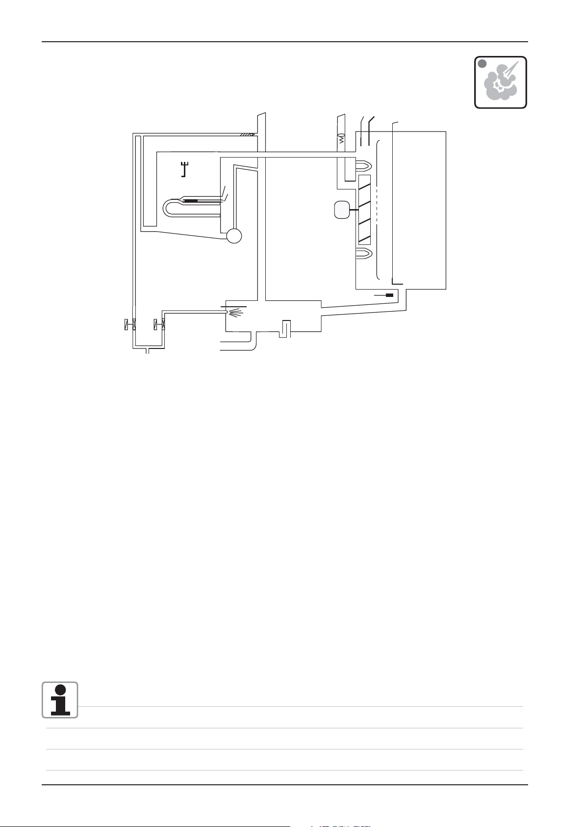
SCC Electric - Basic principle
Y
S4
S2
SCC
B1
F4
M3
B6 - B11
B5
F3
M4
Care
M12
Y4
1
Y3
S11
B2
Y2
S12
M7
P1
M1
B4
S3
M6
B1 Thermocouple interior cabinet
B2 Thermocouple quenching
B4 Thermocouple humidity
B5 Thermocouple steam generator (preheat, 180°C (356°F) max)
B6-B11 Thermocouples core temperature
F3 Safety thermostat steam generator 160°C (320°F)
F4 Safety thermostat interior cabinet 360°C (680°F)
Y1 Solenoid valve lling
Y2 Solenoid valve quenching
Y3 Solenoid valve moistening
Y4 Solenoid valve care
M1 Fan motor bottom
M3 Humidity ap motor
M4 SC-pump
M6 CleanJet pump
M7 Motor drain valve / ball valve
M12 Care pump
S2 Level electrode
S3 Door reed switch
S4 Micro switch humidity motor
S11 CDS sensor
S12 Micro switch drain valve
P1 Pressure sensor humidity
SCC 201/202 only:
M2 Fan motor top with jumper ( oor units only)
Edition 10-2008a
45
Page 46

SCC
Parts identification
(no CareControl)
17
19
1
2
6
5
7
3
4
18
20
21
16
11
8
10
9
12
14
15
1
2
3
13
12
13
14
22
23
46
4
5
6
7
8
9
10
11
15
16
17
18
19
20
21
22
Edition 10-2008a
Page 47

SCC
Parts identi cation CareControl
1
2
1
2
3
3
2
4
11
3
1
2
3
4
11
4
11
4
Edition 10-2008a
47
Page 48

SCC
General information to software version SCC 04-01-01
Software SCC 04-01-01 can also be used for units with index „E“ (from 04-2004).
With this software you have the following options:
Using the button “Cleanjet request” you can select the “Intelligent Cleanjet request”.
In this case the cleanjet request will be based on used cooking programs, tempratures
and cooking duration.
Selecting Cleanjet you will see the below symbol in window 4 of your display:
The second setting to choose is Cleanjet request based on cooking time only (as known from older
software versions).
In order to deselect the Cleanjet request (turn symbol from red to blue again) select time functions
and setb time to “0”..
In Service Mode Basic Settings position 26 you select „Softwater“ ON to indicate only the half
amount of detergent tabs when cleanjet is choosen. The individual tab setting (as available since
software SCC 03-01-01) is no more existing.
Software SCC 04-01-01 in units with index „G“ (from 10-2008)
Basic Settings 26 „Softwater“
In Service Mode Basic Settings position 26 you select „Softwater“ ON to indicate only the half
amount of detergent tabs when cleanjet is choosen.
Basic Settings 28 „Selftest“:
After installation the unit will ask the user to start a Selftest. Water MUST be connected!
After the Clima Control valve and the drain valve have initialised the steam generator will ll,
SC pump will start shortly and Y1 will re ll again.
In case the temperatures of B1, B2 and B4 are below 40°C now “Start” will be displayed.
After pressing “Start” the unit will adapt to the present installation conditions (duration appr. 15 min).
Should the unit be installed later at a different location, this “Selftest” can be re-initialised by setting
“Selftest” to ON in basic settings position 28.
Basic Settings 29 „Warranty“:
After rst switch on the unit will prompt the customer to register and validate his second year warranty online under www.rational-ag.com/warranty.
This prompting will discontinue after 4 days.
After registration a warranty certi cate will be issued:
In case the unit was installed in a show room or exhibition, this prompting can be re-initialised by setting “Warranty” to ON in basic settings position 29.
Basic Settings 30 „Steam corrosion control“
The unit automatically recognises if the customer used it predominantely in steam mode. In case this
usage is more than 90% during the last 20 hours of operation the unit will prompt a Cleanjet request
daily regardless of the total duration of cooking time
Basic Settings 31 „Care Control Reset“
By setting the switch to “ON” all Care Control bars will be set to blue.
48
Edition 10-2008a
Page 49

SCC
Controling the SC pump and solenoid valves before starting the cleanjet process:
If the Cleanjet Start key is pressed the unit will check rst for the proper function of the SC pump and
the solenoid valves.
The SC pump is operated shortly until the level electrode shows low water.
In case of failure “Servcie 10” is displayed and Cleanjet can not be started.
Y1 lling solenoid valve is started, function checked by CDS sensor
In case of failure “Low Water” will be indicated
Y3 moistening solenoid valve is started, function checked by CDS sensor
In case of failure Service 41
Y4 care solenoid valve is started, function checked by CDS sensor
In case of failure Service 42
All solenoid valves are switched off, CDS shall not send any pulses;
In case of failure Service 43
New Service Error codes
Service 40
Care pump faulty or does not ll enough care solution into steam generator;
- After lling of the care solution into the steam generator the CDS sensor sends too many pulses
until the level electrode recognises water.
- Cleanjet nishes without care phase;
- Reset by successfull completion of Cleanjet process;
Service 41
- Solenoid valve Y3 defective or moistening nozzle blocked; CDS does not send any pulses;
- Reset error by successfull CDS measuring during next Cleanjet start;
Service 42
- Solenoid Y4 Care defective or hose to care container vlocked or kinked; CDS does not send any pulses;
- Reset error by successfull CDS measuring during next Cleanjet start;
Service 43
- CDS sensor sends always pulses; Solenoid Y1, Y3 or Y4 is passing water
- Reset error by successfull CDS measuring during next Cleanjet start (Self test)
Service 44
- No temperature raise during recognised by B5 during steaming time while being in Cleanjet phase
- Reset error by successfull B5 tempoerature measuring during next Cleanjet;
Service 110
- Malfunction of SC pump during the time when Care solution was inside the steam generator,
- Reset error by successfull completing a cleanjet abort cycle;
Service 120
- After operating care pump M12 ( lling care solution into steam generator) and topping up with water (Y1)
the level electrode does not recognise water;
- Y1 or level electrode defective;
- Display only after twice starting lling solenoid Y1 yet no water is detected;
- Reset error by successfull completing a cleanjet abort cycle;
Edition 10-2008a
49
Page 50

SCC
It is possible to abort the cleanjet program. However the abort program of 30min. can not be shortened again as the steam generator must be neutralised from possible remaining care solution.
Cleanjet Abort program
During the abort program the steam generator will first be filled with Y1. After draining the steam egnerator it will be filled a second time to a level above the level electrode. After a second draining the
steam generator will fill again exactly to the level electorde.
In case the level electrode does not recognise the water Error 120 will be shown.
At the end of the abort program a short steam period and rinsing the cabinet with Cleanjet pump will
follow.
The duration of steam heating time unitl next SC automatic is now 120min (units with index “G”) .
However should the steam generator develop scale because the customer does not use the care
tabs, this time will automatically be reset to 60 minutes.
50
Edition 10-2008a
Page 51

Difference SCC Index „E“ versus Index „G“ SCC Care Control
Y
Y
B4
B5
F3
B1
F4
B6
M3
S4
S2
SCC
Index „E“
B5
F3
M4
S11
Y3
1
B2
Y2
S12
M7
S2
P1
M1
B4
M6
B1
F4
M3
S4
B6 - B11
P1
M1
Index „G“
Y4
Y3
1
S11
Y2
Care
B2
M4
S3
M12
M6
S12
M7
Edition 10-2008a
51
Page 52

SCC
Sequence Cleanjet+Care Process: 1. step - Cleaning cabinet; example: SCC 61, Index G
Prepare Cleanjet Cleanjet Phase 1 Cleanjet Phase 2 Prepare for care phase
SC Pump M4 1
0
Solenoid Y1 lling steam generator 1
52
Function test (CDS) 0
Function test (CDS) 0
Solenoid Y3 moistening 1
Solenoid Y4 Care 1
Function test (CDS) 0
Edition 10-2008a
Drain valve M7 1
0
Solenoid Y2 quenching
Filling quenching box (pre-cleaning) 1
Level control by prm signal M1 0
Solenoid Y3 moistening 1
Filling quenching box Phase 2 0
level control by CDS
Cleanjet pump M6 1
1. Phase Cleanjet 0
2. Phase Cleanjet
Steam heating
Pre heating steam generator
Steam Cabinet 90°C
Page 53

SCC
Sequence Cleanjet+Care Process: 2. step - Care Steam generator and cabinet; example: SCC 61, Index G
Prepare care solution Care process Neutralising steam generator and cabinet
Service 110Service 120
Solenoid Y4 Care
Care Tabs are disolved in several setps 1
Drain care solution from container 0
Care Pump M12
Pump care solution into steam generator 1
Pump remaining care solution from container 0
Drain valve M7 1
0
Solenoid Filling Y1
Topping up of care solution above level electrode 1
Fill steam generator 0
SC-Pump M4 , Partial separation of care solution
from steam generator to quenching box 1
Rinse steam generator 0
Level electrode S2 1
Edition 10-2008a
0
Solenoid Moistening Y3
Topping up of care solution for cabinet 1
0
Steam heating element to 80° water temperature 1
Neutralising of cabinet and steam generator 0
Cleanjet Pump M6 1
Pumping of care solution through cabinet 0
53
Page 54

SCC
SCC pcb (42.00.002)
X7
42.00.002 REV 802
Operator PCB
X5 X2 X6 X4 X3
A3 Add on pcb
CPU
X7
CPU
X8
Add on X2 B6-11 thermocouple core probe
Add on X3 B1 thermocouple interior cabinet
Add on X4 B2 thermocouple quenching
Add on X5 B4 thermocouple ClimaPlus
X12
Add on X6 B5 thermocouple Steam generator
X11
Add on X10 Central dial
Add on X50 External EEPROM
X1
Add on X51 BUS interface
X8
X50
X103
Add on X52 RS232 interface
Add on X53 USB interface (up to 12-2005)
and power supply for cpu from I/O pcb
Add on X54 USB intefarce
Add on X102 TouchPad connection
X51
X2
Battery
X54
X52
V10 V9 V8
X10
X102
X110
LED Code: SCC PCB
Green LED on - ok
Red LED blinks 1x during re-booting when switching on - ok
X1 P1 pressure sensor
X2 Free
X7 200 - 240V input to I/0 Switch
X8 Buzzer
X11 ClimaPlus motor / Micro switch
X12 Level electrode
X110 Power suply for display 2,5 - 0 - 2,5
54
Green LED off - : Bus cable defective; CPU defective; I/O pcb or transformer defective
Red LED on: CPU defective
Red LED doesn‘t blink during re-booting when switching on - CPU defective
Yellow LED blinking: No operational software / CPU defective
Edition 10-2008a
Page 55

SCC
New I/O PCB SCC (42.00.064P)
Wires of pcb edge connectors are pointing to component side of pcb!
24 25 26
23
X 23.1
X 24.1
X 25.1
X 26.1
75
21
20
19
18
K1:L1
F2: N
X 75
X 20.1
X 19.1
X 18.1
230 V
X 21.1
2A T
230 V
230 V
2A T
N
Y4
A1
A2
230 V
M12
M
~
A1
A1
A1
M4
M
~
M6
M
~
SSR2: B-
SSR2: A-
SSR1: B-
SSR1: A-
+ 12V
LED Gr
A2
Y1
Y1
230 V
A2
Y2
Y2
230 V
A2
Y3
Y3
230 V
LED Ye
12 V DC
12 V DC
+
M7
16 V DC
_
M
S12
12 V DC
S3
12 V AC
11,5 V AC
11,5 V
H1
AC
GND
OUT
IN
CDS-HALL
X 27.1
X 14.1
X 13.1
12 V DC
X 15.1
1234
ON
T1
X 17.1
27
14
13
15
17
16
X 3X 4
X 16.1
18: SC-pump M4, Cleanjet pump M6
19: Solenoid vales Y1- lling, Y2 - quenching, Y3 - moistening
20. Energy optimizing plug with link on 5-6 used only on I/O pcb with 12 relais card!
21. 230V input
75. Care pump M12 and Care solenoid Y4 (free when used in Index “E” unit)
23. Connection to Ultravent (used for Ultravent without BUS connection only)
24. Output 12VDC to SSR
25. Output 12VDC to M7 drain valve, S12 micro switch drain valve
26. free
27. Output 12VDC to door contact
14. Input from Control transformer T1, 11.5V interior light, 12V CPU,
13. Output 11.5VAC to interior cabinet light
15. Output 12VDC to CDS sensor
17. Link Care unit (only existing when build into an Index “G” unit)
16. free
X3, X4. BUS connection
LED Code: I/O PCB
Green LED on - ok
Green LED off during operation ok
Yellow LED always blinking: unit switched off, unit in booting process, DIP switches not all
set to OFF, bus connection defective
Green LED off: I/O PCB defectice, Transformer defective
Edition 10-2008a
55
Page 56

SCC
Fan motor SCC 40.00.274
LED
Jumper 40.01.581 is used on oor model 201 and 202 for top position motor only!
Jumper is not used on models 61 - 102 with one motor only!
(Service 34 will be shown when jumper is set wrongly)
Jumper
LED code fan motor SCC and CM from 04/2004
Reason Remedy
1x Motor doesn’t start, no changing
signal from hallsensor
2x Voltage too low on motor pcb Check supply voltage or
3x Voltage too high on motor pcb Check supply voltage or
Check for motor blockage or change motor.
change motor.
change motor.
4x rpm measurement defective Change motor.
5x Motor pcb temperature >105°C Check cooling system (cooling fan, air
intake lter), otherwise change motor
6x Supply voltage <80V Check power supply
(F1-F2)
7x Motor pcb defective Change motor.
8x Motor pcb defective Change motor.
Fan motor SCC 40.00.276 for units 3AC 400-480V (without neutral)
56
Edition 10-2008a
Page 57

The calculated humidity inside the cabinet is based on:
1. Voltage output signal P1 (depending on fan motor speed, ref: function test #5)
2. Temperature B4 (thermocouple behind motor mounting plate)
3. RPM signal of the fan motor (via BUS signal)
The offset voltage of P1 (Motor not turning) is appr.: 0.45 - 0.55V
SCC
Clima Plus Control SCC
Differential pressure sensor
P1
Thermocouple
Basic rule: The less humid, the higher is the voltage of P1,
The higher the rpm, the higher the voltage of P1.
RPM P1 (approx. Volt)
Dry 1,1
Speed 500rpm Wet 0,7
Combi 0,6
Dry 2.3
Speed 1250rpm Wet 1.7
Combi 1.5
humidity control
B4
ClimaPlus
RPM
Example: SCC 101 E
Clima Status (approx. value in Pascal)
Indicated values shall NOT be “0” or “85000”
If “0” or “85000” is indicated
re-calibration is needed
rpm measurement
Dry 2.9
Speed 1800rpm Wet 2.4
Combi 1.9
Dry 3,1
Speed 1900rpm Wet 2.5
Combi 2.2
Edition 10-2008a
57
Page 58

SCC
58
Edition 10-2008a
Page 59

SCC - Sequence of events
Y
SCC
Steam: Temperature range 98-103°C (208-218°F)
B1
F4
M3
S4
S2
B5
F3
M4
Care
M12
Y4
Y3
1
S11
B2
Y2
S12
M7
P1
M1
B4
S3
M6
Function step Responsible sensor
1 Select Wet heat (Temp 98-103°C (208-218°F))
B6 - B11
2 Select time or core temperature
3 Close cabinet door Reed switch S3
4 Check water level inside steam generator Level electrode S2 inside Steam Gen
5 Time based preheating of steam generator,
Thermocouple B5 inside Steam Gen.
if B5 is below 85°C (185°F)
6 Timer starts after successful preheating Logic on PCB
7 Steam production up to saturation in cabinet Pressure sensor P1, Thermocouple B4
rpm motor via BUS
8 Adding of Hot Air from 70°C (158°F)
Cabinet sensor B1
only possible, if 70% humidity reached
9 Quenching (set to 70°C/158°F) Thermocouple B2
Note: Steam heating only active when humidity ap (S4) is in closed position!
Additional functions possible: 4 Fan speeds (Standard = Level 3), pulsed fan wheel, ½ Energy,
HACCP output, T.
Edition 10-2008a
59
Page 60

SCC
Y
1
Y2
Y3
B2
M1
SCC - Sequence of events
Low temperature steam: Temperature range 30-97°C (85-207°F)
B1
S11
F4
M3
S4
S2
B5
F3
M4
Care
M12
Y4
S12
M7
P1
B4
S3
M6
B6 - B11
Function step Responsible sensor
1 Select Wet heat (Temp 30-97°C (85-207°F))
2 Select time or core temperature
3 Close cabinet door Reed switch S3
4 Check water level inside steam generator Level electrode S2 inside Steam Gen
5 Time based preheating of steam generator,
Thermocouple B5 inside Steam Gen.
if B5 is below 85°C (185°F)
6 Timer starts after successful preheating Logic on PCB
7 Steam supply until set temperature inside cabinet
Cabinet sensor B1
is reached
8 Adding of Hot Air from 93°C (200°F) possible
Cabinet sensor B1
(only 50%)
9 Quenching (set to 70°C/158°F) Thermocouple B2
Note: Steam heating only active when humidity ap (S4) is in closed position!
Below 98°C fan at lowest speed when no energy required for longer than 2 minutes.
Additional functions possible: 4 Fan speeds (Standard = Level 3), pulsed fan wheel, ½ Energy,
HACCP output, T.
60
Edition 10-2008a
Page 61

SCC - Sequence of events
Y
SCC
Forced steam: Temperature range 104-130°C (219-266°F)
M3
S4
S2
B5
F3
M4
Care
M12
Y4
Y3
1
S11
B2
Y2
S12
M7
P1
B4
M6
B1
F4
M1
S3
B6 - B11
Function step Responsible sensor
1 Select Wet heat (Temp 104-130°C (219-266°F))
2 Select time or core temperature
3 Close cabinet door Reed switch S3
4 Check water level inside steam generator Level electrode S2 inside Steam Gen
5 Time based preheating of steam generator,
Thermocouple B5 inside Steam Gen.
if B5 is below 85°C (185°F)
6 Timer starts after successful preheating Logic on PCB
7 Steam supply until saturation is reached inside
cabinet
Pressure sensor P1, Thermocouple B4
rpm motor via BUS
8 Adding of hot air only when humidity is above 85% Cabinet sensor B1
9 Quenching (set to 70°C/158°F) Thermocouple B2
Note: Steam heating only active when humidity ap (S4) is in closed position!
Additional functions possible: 4 Fan speeds (Standard = Level 3), pulsed fan wheel, ½ Energy,
HACCP output, T.
Edition 10-2008a
61
Page 62

SCC
Y
SCC - Sequence of events
Combi steam: Temperature range 141-300°C (286-572°F)
S2
B1
F4
M3
S4
B6 - B11
B5
F3
M4
Care
M12
Y4
Y3
1
S11
Function step Responsible sensor
B2
Y2
S12
M7
P1
M1
B4
S3
M6
1 Select Wet and Dry heat (Temp 141-300°C (286-572°F)
2 Select time or core temperature
3 Close cabinet door Reed switch S3
4 Check water level inside steam generator Level electrode S2 inside Steam Gen
5 Time based preheating of steam generator,
Thermocouple B5 inside Steam Gen.
if B5 is below 85°C (185°F)
6 Timer starts after successful preheating Logic on PCB
7
Heat up cabinet with Hot Air until set temperature
Cabinet sensor B1
is reached;
Priority Hot Air
8 Adding of steam up to set steam saturation Pressure sensor P1, Thermocouple B4
rpm motor via BUS
9 Quenching (set to 70°C/158°F) Thermocouple B2
Note: Steam heating only active when humidity ap (S4) is in closed position!
Additional functions possible: 4 Fan speeds (Standard = Level 3), pulsed fan wheel, ½ Energy,
HACCP output, T.
62
Edition 10-2008a
Page 63

SCC - Sequence of events
Y
Finishing: Temperature range 30-140°C (86-284°F)
S2
SCC
B1
F4
M3
S4
B6 - B11
B5
F3
M4
Care
M12
Y4
Y3
1
S11
B2
Y2
S12
M7
P1
M1
B4
S3
M6
Function step Responsible sensor
1 Select Wet and Dry heat (30-140°C (86-284°F))
2 Select time or core temperature
3 Close cabinet door Reed switch S3
4 Check water level inside steam generator Level electrode S2 inside Steam Gen
5 Time based preheating of steam generator,
Thermocouple B5 inside Steam Gen.
if B5 is below 85°C (185°F)
6 Timer starts after successful preheating Logic on PCB
7a Electric units: alternating
8 s Hot air supply
8 s Steam supply
7b Gas units: alternating
20 s Hot air supply
20 s Steam supply
Hot air: Cabinet sensor B1
Steam: Pressure sensor P1, Thermocou-
ple B4 rpm motor via BUS
Hot air: Cabinet sensor B1
Steam: Pressure sensor P1, Thermocou-
ple B4 rpm motor via BUS
8 Quenching (set to 70°C/158°F) Thermocouple B2
Note: Steam heating only active when humidity ap (S4) is in closed position!
Below 98°C fan at lowest speed when no energy required for longer than 2 minutes.
Additional functions possible: 4 Fan speeds (Standard = Level 3), pulsed fan wheel, ½ Energy,
HACCP output, T.
Edition 10-2008a
63
Page 64

SCC
Y
SCC - Sequence of events
Hot air: Temperature range 30-300°C (86-576°F)
S2
B5
F3
M4
Care
M12
Y4
Y3
1
S11
B2
Y2
S12
M7
M3
S4
P1
B4
M6
B1
F4
M1
S3
B6 - B11
Function step Responsible sensor
1 Select Dry heat
Select time or core temperature
2
Close cabinet door Reed switch S3
3
4 Timer starts at once Logic on PCB
5 Heating of cabinet with Hot air to set temperature Cabinet sensor B1
Quenching (set to 70°C/158°F) Thermocouple B2
6
Below 98°C fan at lowest speed when no energy required for longer than 2 minutes.
Additional functions possible: 4 Fan speeds (Standard = Level 3), pulsed fan wheel, ½ Energy,
HACCP output, T.
ClimaPlus permanently measures the humidity evaporating from the food.
If needed the clima plus valve is opened to reduce the humidity to the set value.
64
Edition 10-2008a
Page 65

on
1
Service level SCC
1) Switch on unit
2) Set DIP 1 on operator PCB to „“ON““ position
234
3) Press service key
4) On the displays the following available Service - modules will be shown
Diagnostic
Running Times
Basic Settings
SCC
Function Test
5) Activate selected service module by push on display or push on central dial
6) Deactivate selected service module by pushing on “return“ symbol
Returning to SCC display / cooking mode only possible from Diagnostic mode!
1 - DIAGNOSTIC
Cabinet B1
130°C 345°C
act max
RESET
on
1
234
7) Set DIP 1 on operator PCB to “OFF“ position to deactivate Service level
Starting with software version 01-07-02 gas related information is not shown on electric units!
Function data entry through central dial: press dial icon rst, frame will turn to red ==> only
no the value can be changed.
Edition 10-2008a
65
Page 66

SCC
66
Edition 10-2008a
Page 67

DIAGNOSTIC
1 - Cabinet B1
SCC
Diagnostic mode SCC
2 - Quenching B2
3 - Not used B3
4 - Humidity B4
5 - Steam Generator B5
6-11 - Core Temp B6-11
12 - Temperature PCB
13 - Level Electrode S2
14 - Door Contact S3
17 - Clima Motor
M3 / S4
18 - Hot Air
19 - Steam
20 - SC Automatic
21 - Volume
22 - M6 CleanJet pump
Y2 - Quenching Solenoid
23 - M7 Drain valve
S12 Micro switch
23.1 M12 Care motor
Y4 Solenoid care
15 - Clima
P1 - B4 - RPM
16 - Clima Status
16.1 - Cal.Geodat
Auto. Calibration
Edition 10-2008a
24 - Service Error history
25 - Gas Error history
67
Page 68

SCC
Diagnostic mode SCC
1 - DIAGNOSTIC
Cabinet B1
130°C 345°C
act max
70°C 95°C
act max
RESET
2 - DIAGNOSTIC
Quenching B2
RESET
3 - DIAGNOSTIC
- Temp. range: -30 - 340°C (-22 - 644°F)
- 900°C (655°C until SW version 01-07-08)
broken thermocouple or loose plug
- act: actual temperature
- max: maximum recorded temperature
- to reset max value press RESET
- Temp. range: -30 - 340°C (-22 - 644°F)
- 900°C (655°C until SW version 01-07-08)
broken thermocouple or loose plug
- act: actual temperature
- max: maximum recorded temperature
- to reset max value press RESET
not used
900°C 900°C
130°C 345°C
act max
Steam Generator B5
104°C 115°C
act max
RESET
4 - DIAGNOSTIC
Humidity B4
RESET
5 - DIAGNOSTIC
RESET
- B3 free, no function
- Temp. range: -30 - 340°C (-22 - 644°F)
- 900°C (655°C until SW version 01-07-08)
broken thermocouple or loose plug
- act: actual temperature
- max: maximum recorded temperature
- to reset max value press RESET
- Temp. range: -30 - 340°C (-22 - 644°F)
- 900°C (655°C until SW version 01-07-08)
broken thermocouple or loose plug
- act: actual temperature
- max: maximum recorded temperature
- to reset max value press RESET
68
Edition 10-2008a
Page 69

6-11 - DIAGNOSTIC
Core Temp. B6 -11
104°C 115°C
act max
RESET
12 - DIAGNOSTIC
SCC
Diagnostic mode SCC
- Temp. range: -30 - 340°C (-22 - 644°F)
- 900°C (655°C until SW version 01-07-08)
broken thermocouple or loose plug
- act: actual temperature
- max: maximum recorded temperature
- to reset max value press RESET
Temperature PCB
130°C 345°C
act max
Level Electrode S2
S2 1 - 0
Y1 0 - 1
RESET
13 - DIAGNOSTIC
14 - DIAGNOSTIC
- Temp. range: -30 - 85°C
- act: actual temperature
- max: maximum recorded temperature
- to reset max value press RESET
- above 75°C (167°F) Warning=> Clean air lter
- above 85°C (185°F) => Service 29
S2 = 1 => Water level reached
S2 = 0 => Water level too low
Y1 = 0 => Filling solenoid not active
Y1 = 1 => Filling solenoid active
Door contact S3
1 - 0
15 - DIAGNOSTIC
Clima
P1 - B4 - RPM
Default out
0,48V 2,24V
B4 85% rpm
145°C 1850
1 => Door closed
0 => Door open
Default: 0,4 - 0,55V (Value when fan motor not turning)
Output signal (out):
ca. 1,3 - 1,6V Combination 200°C
ca. 1,5 - 1,9V Steam 100°C
ca. 2,5 - 3,0V Hot air 60°C
Edition 10-2008a
69
Page 70

SCC
Diagnostic mode SCC
16 - DIAGNOSTIC
Clima Status
Cal. Speed 1 Error
xxx rpm ---
Dry Wet Combi
xxxx xxxx xxxx
16.1 - DIAGNOSTIC
Cal.Geodat
Auto. Calibration
-1.0000 1.0000
m.val a.val
M3 0 - 1
RESET
ON
17 - DIAGNOSTIC
Clima Motor
- Display of calibration values relative to the different motor
speeds and unit size;
- Normal values between 72000-130000
Automatic Humidity calibration
AFTER manual calibration this feature is set to „OFF“.
Do not reset to „ON“ after manual calibration.
When „ON“ Autocalibration will be done when cabinet is cold
and the steam generator is preheating;
1.0000 is only shown when autocalibration is „OFF“
M3: Motor ClimaPlus Flap
S4: Micro switch ClimaPlus ap
No steam production, when S4 is „0“ => open!
S4 1 - 0
18 - DIAGNOSTIC
Hot Air
50%
19 - DIAGNOSTIC
Steam
100%
possible values:
0: hot air heating off
50%: hot air heating 50%
100%: hot air heating 100%
possible values:
0: steam heating off
50%: steam heating 50%
100%: steam heating 100%
70
Edition 10-2008a
Page 71

Diagnostic mode SCC
SCC
20 - DIAGNOSTIC
SC Automatic
53min
45sec 60min
21 - DIAGNOSTIC
Calc- 3,2L
check
Fill Norm
3,6L 4,2L
Test
Volume
22 - DIAGNOSTIC
Window 3:
- 53min since last SC -automatic
- Pressing Test => time will be set to set time plus 1 minute
Window 4:
- 45sec: Preset SC-duration (20-90sec)
- 60min: Preset SC-time (20-90min)
Calccheck 3,2l: Release volume for indication CalcCheck
Fill 3,6l: actual measured water content steam generator
Norm 4,2l: Volume when steam generator is new and clean
M6 CleanJet Pump
Y2 Quenching Sol.
M6 0 - 1
Y2 0 - 1
23 - DIAGNOSTIC
M7 Drain valve motor
S12 Micro switch
M7 0 - 1
S12 1 - 0
23.1 - DIAGNOSTIC
M12 Care motor
Y4 Care Solenoid
M6: CleanJet Pump
Y2: solenoid valve quenching
M7: Drain valve motor
S12: Micro switch drain valve
M12 Care motor
Y4 Care Solenoid
Display only from Software SCC 04-01-02
M12 0 - 1
Y4 1 - 0
Edition 10-2008a
71
Page 72

SCC
Diagnostic mode SCC
24 - DIAGNOSTIC
Service error history
i.e.: (1) Service 10
2006-01-11 17:11:10
25 - DIAGNOSTIC
Gas error history
Gas 1
1: 0: 09.10.05 9:17 32
- since SW Version 01-07-09
display of the last 10 stored error messages
(ref: Service error messages)
- since software version 01-07-09
Indication of the last 16 stored ignition box error
messages including date and time.
0= ignition box top
1= ignition box bottom
Only starting with Software version 01-07-09 the entire information of the service level can
be downloaded to memory stick when DIP switch 1 is set to „1“.
SInce Software version 02-01-01 the service package can be downloaded also by the customer without setting the dip switch using the function key followed by pressing the USB key
and Info key.
Info
72
Edition 10-2008a
Page 73

Running Times
SCC
Running Times SCC
1 - S3 Door openings
2 - S12 Ball valve openings
3 - Y1 Valve lling
4 - Y2 Valve quenching
5 - Y3 valve moistening
5.1 - Y4 Care solenoid valve
6 - M4 SC pump
7 - M6 Cleaning pump
10 - Hot air heating time
11 - Steam mode
12 - Hot air mode
13 - Combi Steam mode
14 - Vario steam mode
15 - Finishing mode
16.1 - 7 - CleanJet program‘s
17 - Cool down
8 - M7 Ball valve
8.1 - Care pump
9 - Steam heating time
Edition 10-2008a
18 - Total running time unit
19 - Emergency Controller
73
Page 74

SCC
Running Times SCC
1 - Running Times
S3 Door openings
Number of events
Reset possible
835
Reset
2 - Running Times
S12 Ball Valve Openings
238
Reset
3 - Running Times
Y1 Valve Filling
120 min
Reset
4 - Running Times
Number of events
Reset possible
Total minutes
Reset possible
74
Y2 Valve Quenching
1460 min
Reset
5 - Running Times
Y3 Valve Moistening
48 min
Reset
Total minutes
Reset possible
Total minutes
Reset possible
Edition 10-2008a
Page 75

5.1 - Running Times
Y4 Care solenoid valve
715 min
6 - Running Times
SCC
Running Times SCC
Total minutes
Reset possible
M4 SC Pump
715 min
7 - Running Times
M6 Cleaning Pump
315 min
8 - Running Times
M7 Ball Valve
55 min
Total minutes
Reset possible
Total minutes
Reset possible
Total minutes
Reset possible
8.1 - Running Times
M12 Care motor
62 min
Total minutes
Reset possible
Edition 10-2008a
75
Page 76

SCC
Running Times SCC
9 - Running Times
Steam Heating Time
4hrs
Reset
10 - Running Times
Hot Air Heating Time
4hrs
Reset
11 - Running Times
Steam Mode
Total hours
Total hours
Total hours
4hrs
12 - Running Times
Hot Air Mode
4hrs
12 - Running Times
Hot Air Mode
4hrs
Total hours
Total hours
76
Edition 10-2008a
Page 77

13 - Running Times
Combi Steam Mode
4hrs
14 - Running Times
Vario Steam Mode
<97°C
4hrs
SCC
Running Times SCC
Total hours
Total hours
15 - Running Times
Finishing Mode
Finishing 97-140°C
4hrs
16.1-16.6 - Running Times
Cleaning Program
55 hrs
Total hours
Total hours
Reset NOT possible
16.1 - Rinse w/o tabs
16.2 - Rinse
16.3 - Intermediate Clean
16.4 - Light
16.5 - Medium
16.6 - Strong
17 - Running Times
Cool Down
4hrs
Total hours
Edition 10-2008a
77
Page 78

SCC
18 - Running Times
Total running time unit
4hrs
19 - Running Times
Emergency controler
1
Reset
Total hours
Number of events
Reset possible
78
Edition 10-2008a
Page 79

Basic Settings
NOTE: To validate changes made, switch unit OFF and ON again!
Wait 30 secondes before switching off.
SCC
Basic Setting
1.1 - Calibration
1.2 Initialisation
drain valve, humidity ap
2 - Gas type
3 - CO
4 - Installation altitude
5 - Gas blower speed Steam
6 - Gas blower speed Hot Air top
7 -
screw setting
2
Gas blower speed Hot Air botto
m
17 - IP address
18 - Subnet mask
19 Gateway address
20 <USB> IP address
21 <USB> Server IP address
22 <USB> Subnet mask
23 - Plate á la carte
from SW 02-01
8 - CDS Sensor
9 - Volume steam generator new
10 - SC Automatic
11 - SC Pump
12 - Show mode
13 - Quench. Temp. Dry Heat
14 - Quench. Temp. Moist Heat
15 - Quench. Temp. OFF
16.1 - Service Phone Setting
24 - Plated banquet
from SW 02-01
25 - Level Control
26 - Softwater
27 - Forced Clean
28 - Self test
29 - Warranty
30 - Steam Corrosion switch
16.2 - ChefLine Phone Setting
Edition 10-2008a
31 -Care control reset
79
Page 80

SCC
Basic Settings (To validate changes made, switch unit OFF and ON again!)
1.1 - Basic Setting
Calibration
B1 B4 Step
99°C 95°C 90
P1 RPM Error
1,55V 1550 0
1.2 - Basic Setting
Drain valve (Dv)
Flap (F)
Dv (t0) Dv(t1) F-t
8,4s 28,2s 19,4s
2 - Basic Setting
(only Gas units)
Gas type
3B/P - 3P-
Nat.H - Nat.L - A12/13
Start
Start
Start
- To prepare unit for calibration run,
see page „Calibration“
- When error is shown switch off and follow Error messages for
repair.
Afterwards start calibration run once again.
- Drain valve or flap shall be initialised after indication of
Service 26, 27 or 21.
Times shown above are average times.
Dv(t0): time needed for 90° turning of drain valve
(Drain valve open - closed)
Dv(t1):
F-t:
time needed for
270°
time needed for 360°
turning of drain valve
turning of ClimaPlus flap
- Selection of connected type of gas
- Con
rm adjustment by touch on „Store“ icon.
- Corresponding blower speeds are automatically selected and
loaded.
- Unit must be switched off and on to store new setting!
- A ue gas analysis MUST be done!
3 - Basic Setting
(only Gas units)
Nat H (G20)
Steam
4,3mm 2,8mm 2,9mm
-499-0, 0-499, 500-1000
1000-1500,1500-2000 etc
Hot air T Hot air B
4 - Basic Setting
(only Gas units)
Installation Altitude
above sea level
80
- Pre set lenghts of CO
- After gas conversion or changing gas valve adjust CO
screws
2
screw
2
- A ue gas analysis MUST be done!
- Since software version 01-07-02
- Select installation altitude with dial icon
- After 5 sec. „Store“ icon will show
- To con rm press „store“ icon and switch unit off and on again.
- A ue gas analysis MUST be done!
Edition 10-2008a
Page 81

Basic Settings (To validate changes made, switch unit OFF and ON again!)
5 - Basic Setting
(only Gas units)
Gas blower speed Steam
- Adjusting speed of blower motor steam (+/ -10%)
rpm
Min rpm
xxxx
6 - Basic Setting
(only Gas units)
Gas blower speed Hot Air Top
rpm
Start rpm
xxxx
Max rpm
xxxx
Start rpm
xxxx
- Modi ed speed will be shown next to dial icon.
- To store new setting switch unit off and on again.
- A ue gas analysis MUST be done!
- Adjusting speed of blower motor hot air top (+/ -10%)
- Modi ed speed will be shown next to dial icon.
- To store new setting switch unit off and on again.
- A ue gas analysis MUST be done!
SCC
Min rpm
xxxx
7 - Basic Setting
(only Gas units 201 - 202)
Gas blower speed Hot Air bottom
rpm
Min rpm
xxxx
8 - Basic Setting
CDS
1000
Max rpm
xxxx
Start rpm
xxxx
Max rpm
xxxx
- Adjusting speed of blower motor hot air bottom (+/ -10%)
- Modi ed speed will be shown next to dial icon.
- To store new setting switch unit off and on again.
- A ue gas analysis MUST be done!
- Changing the number of pulses for the CDS sensor;
9 - Basic Setting
Volume Steam Generator NEW
After manual
Reset
descaling
After changing
Reset
steam generator
- Since Software version 01-07-02
- After manual descaling:
Press Reset for 5 seconds; Steam generator will be pumped
off and lled again, CDS indication will be resetted;
- After changing steam generator:
Press Reset for 5 seconds; Steam generator volume will be
reset to factory setting;
Edition 10-2008a
81
Page 82

SCC
Basic Settings (To validate changes made, switch unit OFF and ON again!)
10 - Basic Setting
SC Automatic
45sec (20-90sec)
60min (20-120min)
11 - Basic Setting
SC Pumpe
CONTINUOUS
Puls
12 - Basic Setting
Show mode
ON - OFF
- Activation by touch on dial icon
- Adjust duration with dial
- Con rm adjustment by touch on dial icon
- Activation by touch on dial icon
- Adjust pumping mode with dial
- Con rm adjustment by touch on dial icon
- Activation by touch on dial icon
- Adjust mode with dial
- Con rm adjustment by touch on dial icon
13 - Basic Setting
Quench. Temp. Hot Air
90°C
(20 - 130°C)
14 - Basic Setting
Quench. Temp. Moist Heat
70°C
(20 - 130°C)
82
- Setting quenching temperature in hot air mode
- Activation by touch on dial icon
- Adjust temperature with dial
- Con rm adjustment by touch on dial icon
- Setting quenching temperature in all steam modes
- Activation by touch on dial icon
- Adjust temperature with dial
- Con rm adjustment by touch on dial icon
Edition 10-2008a
Page 83

Basic Settings (To validate changes made, switch unit OFF and ON again!)
15 - Basic Setting
SCC
Quench. Temp. OFF
Ablöschtemperatur ohne Betriebart
120°C
(20 - 130°C)
16.1 - Basic Setting
Service phone setting
EDIT
08191-327
16.1 - Basic Setting
Service phone setting
08191-327_
0 1 2 3 4 5 6 7 8 9
- Setting quenching temperature when no mode is selected
- Activation by touch on dial icon
- Adjust temperature with dial
- Con rm adjustment by touch on dial icon
- Press EDIT key; new display
- Select new number with central dial
- Con rm number by pressing central dial
- „delete“ erases last digit
- „store“ will memorize number and returns to former display
storedelete
16.2 - Basic Setting
ChefLine phone setting
EDIT
08191-3270
17 - Basic Setting
IP Address
EDIT
168.65.8.217
ref: 16.1 Basic Setting
ref: 16.1 Basic Setting
Edition 10-2008a
83
Page 84

SCC
Basic Settings (To validate changes made, switch unit OFF and ON again!)
18 - Basic Setting
Subnet mask
ref: 16.1 Basic Setting
EDIT
19 - Basic Setting
Gateway address
(Ethernet)
EDIT
ref: 16.1 Basic Setting
20 - Basic Setting
<USB> IP
21 - Basic Setting
<USB> Server IP Address
22 - Basic Setting
Address
EDIT
EDIT
ref: 16.1 Basic Setting
ref: 16.1 Basic Setting
84
<USB> Subnet Mask
ref: 16.1 Basic Setting
EDIT
Edition 10-2008a
Page 85

SCC
Basic Settings (To validate changes made, switch unit OFF and ON again!)
23 - Basic Setting
Plate á la carte
- Press dial icon
700-899g
24 - Basic Setting
- Adjust to correct plate weight
up to 700g; 700-899g; 900-1099g; above 1100g
- Press dial to memorize new setting
Plated Banquet
700-899g
25 - Basic settings
Level Control
Number of Shelves
5
26 - Basic settings
CleanJet
Softwater
- Press dial icon
- Adjust to correct plate weight
up to 700g; 700-899g; 900-1099g; above 1100g
- Press dial to memorize new setting
The number of indicated shelves can be indicated for Level
Control
If „0“ is selected the max number of shelves is shown.
61-62: 1-6 levels
all others: 1-10 levels
Selecting Softwater “ON” will indicate 50% of the standad cleanr
tabs;
Reset
OFF
27 - Basic Settings
Forced Clean (index E only)
OFF
If setting is „ON“ the operator can use the equipment for the
duration as set in „CleanJet setting“ under „Settings“.
Thereafter he can extend this time for max 2x2hours before a
CleanJet mode MUST be started.
If Forced Clean is set to „ON“ „!“ appears during running
CleanJet program;;
Edition 10-2008a
85
Page 86

SCC
Basic Settings (To validate changes made, switch unit OFF and ON again!)
28 - Basic Settings
Selftest
OFF
29 - Basic Settings
Warranty
OFF
30 - Basic Settings
Steam corrosion control
Basic Settings 28 „Selftest“:
After initial installation the unit will automatically run into a „Selftest“
mode. The operator is prompted to remove all containers and packing
material from the cabinet. After appr. 1 minute a „Start“ buttom will appear under the condition B1, B2 and B4 is below 40°C (104°F).
Note: For this mandatory start-up function water must be connected!
Basic Settings 29 „Warranty“:
After rst switch on the unit will prompt the customer to register and
validate his second year warranty online under www.rational-ag.com/
warranty.
This prompting will discontinue after 4 days.
In case the unit was installed in a show room or exhibition, this
prompting can be re-initialised by setting “Warranty” to ON in basic
settings position 29.
Basic Settings 30 „Steam corrosion control“
The unit automatically recognises if the customer used it predominantely in steam mode. In case this usage is more than 90% during the
last 20 hours of operation the unit will prompt a Cleanjet request daily
regardless of the total duration of cooking time
OFF
30 - Basic Settings
Care control reset
OFF
Basic Settings 31 „Care Control Reset“
By setting the switch to “ON” all Care Control bars will be set to blue.
86
Edition 10-2008a
Page 87

Function Test
SCC
Function test SCC
1 - Steam (Dampf) 50%
not used in Gas units
2 - Steam (Dampf) 100%
3 - Hot Air 50%
Gas - burner top
4 - Hot Air 100%
Gas - burner bottom
5 - Fan motor top
6 - Fan motor bottom
7 - Solenoid valve lling Y1
16 - Gas Hot Air Blower bottom
17 - Buzzer T2
18 - Interior Light H1
19 - Display lights
20 - Exhaust hood
21 - Sicotronic
8 - SC Pump M4
9 - Solenoid quenching Y2
10 - Solenoid Moistening Y3
10.1 - Care valve and pump
Y4 + M12
11 - Humidity ap motor M3
12 - CleanJet Pump M6
13 - Drain Valve Motor M7
14 - Gas Steam Blower
15 - Gas Hot Air Blower Top
Edition 10-2008a
87
Page 88

SCC
Function test SCC
1 - Function
Steam 50%
Temperature B5 103°C
2 - Function Test
Steam 100%
Temperature B5 103°C
3 - Function Test
Hot Air 50%
0 - 1
Test
0 - 1
0 - 1
Start
Start
Start
- Electric units: Steam heating 50%;
- Gas units: not used
- Actual temperature of B5
Attention: Parts are not protected against overload!
- Electric and gas units: Steam heating 100%;
- Indication gas units (window 2): „Steam Gas-Burner“
- Actual temperature of B5
Attention: Parts are not protected against overload!
- Electric units: Hot air heating 50%;
- Gas units: Hot air heating 100%
- Indication window 2:
Table models: „Hot Air Gas-Burner“
Floor models: „Hot Air Gas-Top Burner“
- Actual temperature of B1
Attention: Parts are not protected against overload!
Temperature B1 185°C
4 - Function Test
Hot Air 100%
0 - 1
Temperature B1 185°C
5 - Function Test
Fan motor top
Speed 3
1800rpm
actual speed
xxxx
Start
Start
- Electric units: Hot air heating 100%
- Only gas oor models: Hot air heating 100%
- Indication window 2:
„Hot Air Gas-Bottom Burner“
- Actual temperature of B1
Attention: Parts are not protected against overload!
Fan motor top:
- Select RPM with central dial
(default: second highest RPM):
- Typ 61: 500,1100,1550,1650
- Typ 62, 101, 201: 500,1250,1800,1900
- Typ 102, 202: 550,1450, 2000, 2200
88
Edition 10-2008a
Page 89

6 - Function Test
Fan motor bottom
Speed 4
1900rpm
actual speed
xxxx
7 - Function Test
Solenoid valve lling Y1
1 - 0
Start
Start
SCC
Function test SCC
Fan motor bottom:
- Select RPM with central dial
(default: second highest RPM):
- Typ 61: 500,1100,1550,1650
- Typ 62, 101, 201: 500,1250,1800,1900
- Typ 102, 202: 550,1450,2000,2200
- Activat. of solenoid valve lling Y1
- Level electrode shows 1 = steam generator lled
- Level electrode shows 0 = steam generator partial lled
Level electrode 1 - 0
8 - Function Test
SC Pump M4
1 - 0
Level electrode 1 - 0
9 - Function Test
Solenoid quenching Y2
1 - 0
Temperature B2 36°C
Start
Start
- Activation of SC Pump M4
- Level electrode shows 1 = steam generator lled
- Level electrode shows 0 = steam generator partial lled
- Activation of solenoid valve quenching Y2
- Indication of actual temperature B2
(needed for testing quenching system).
10 - Function Test
Solenoid moistening Y3
0 - 1
Start
- Activation of solenoid valve moistening Y3
Edition 10-2008a
89
Page 90

SCC
Function test SCC
10.1 - Function Test
Care valve and pump
Y4 + M12
0 - 1
Level electrode 1 - 0
11 - Function Test
Humidity ap motor M3
0 - 1
End switch S4 1 - 0
12 - Function Test
Start
Start
Simultaneous activation of Care valve and Care pump
Stop activating the solenoid valve once the electrode shows “1”
contact with water.
If solenoid is longer active the steam generator can self syphon via the care pump and care container!
ClimaPlus motor
S4 shows 1 = Flap closed
S4 shows 0 = Flap open
CleanJet Pump M6
0 - 1
13 - Function Test
Drain Valve Motor M7
Direction 1 -2
S12 1 - 0
15 - Function Test
Gas Steam Blower
Max - Start - Min
Start
Start
Start
Activation CleanJet Pump
Activation drain valve
Direction 1: Clockwise
Direction 2: Counter clockwise
S12 microswitch drain valve
Flue gas analysis Gas blower Steam:
Press START to operate hot air gas burner top;
- CO
-
CO2 cross checking at Min rpm
adustment with CO2 screw at Max rpm
2
CO2 FC rpm
xxx% 5,75 A xxx
90
- Flame current should be always above 4,0 A,
idealy 5,0-5,75 A
Edition 10-2008a
Page 91

16 - Function Test
Gas Hot Air Blower Top
Max - Start - Min
Start
Function test SCC
Flue gas analysis Gas blower Hot air top:
Press START to operate hot air gas burner bottom;
- CO
-
CO2 cross checking at Min rpm
adjustment with CO2 screw at Max rpm
2
SCC
CO2 FC rpm
xxx% 5,25A xxx
Gas Hot Air Blower Bot.
17 - Function Test
Max - Start - Min
CO2 FC rpm
xxx% 5,25A xxx
Buzzer T2
0 - 1
Start
Start
- Flame current should be always above 4,0 A,
ideally 5,0-5,75 A
Flue gas analysis Gas blower Hot air bottom:
Press START to operate hot air gas burner bottom;
- CO
-
CO2 cross checking at Min rpm
adjustment with CO2 screw at Max rpm
2
- Flame current should be always above 4,0 A,
ideally 5,0-5,75 A
Activation buzzer
18 - Function Test
Interior light
19 - Function Test
Display light
Start
Start
Activation interior light
- Testing of all display lights by pushing and holding Start key.
The different lights will be activated in sequence.
Edition 10-2008a
91
Page 92

SCC
Function test SCC
20 - Function Test
Exhaust hood
Ultravent
21 - Function Test
Sicotronic
Start
UltraVent-Relais on I/0-PCB
Start
Sicotronic--Relais on I/0-PCB
92
Edition 10-2008a
Page 93

Error code SCC
SCC
Service 10
SC Pump
Service 11
CDS Sensor
Service 12
CDS Sensor no signal
Service 13
Steam generator
Service 14
Level electrode - water
Service 15
not used
Service 16
PCB with old software
Service 17
EEPROM faulty
Service 18
not used
Service 26
Drain valve closed
Service 27
drain valve doesn‘t close
Service 28
Steam generator above 180°C
Service 29
PCB temperature
Service 30
Humidity control
Service 31.1 - 6
Core probe
Service 32
Ignition box
Service 33
Ignition box, Gas valve
Service 34.xx -
Bus signal
Service 19
not used
Service 20
Thermocouple B1 cabinet
Service 21
Micro switch Clima Plus
Service 22
not used
Service 23
SSR Steam
Service 24
SSR Hot air
Service 25
CleanJet no function - water circ
Service 40
Care pump
Service 41
Solenoid valve Y3
Service 42
Solenoid valve Y4
Service 43
Any solenoid passing water
Service 44
Steam Heating, B5
Service 100
Motor permanent on power
Service 110
SC Pump
Service 120
Care pump, level electrode
Buzzer frequency for faulty thermocouples (counted at 5 seconds intervall)
B1 12x at 5 seconds
B2 6x at 5 seconds
B4 5x at 5 seconds
B5 8x at 5 seconds
Core probe 20x at 5 seconds
Edition 10-2008a
93
Page 94

SCC
Error code SCC
Service 10
SC - Pump
Maintenance needed
Service 11
CDS Sensor
Maintenance needed
Service 12
CDS Sensor without Signal
Maintenance needed
Service 13
Maintenance needed
Only hot air manual possible
- Appears for 30 sec. after switch ON
- Display can be cancelled by touch
- SC-automatic didn‘t work, water level does not decrease
- Check SC-pump and drain hose of steam generator
- Appears for 30 sec. after switch ON
- Display can be cancelled by touch
- Water level o. k., - Level electrode is working
- Too many pulses measured by CDS sensor
- Check electrode or water leakage through check valve
- Appears for 30 sec. after switch ON
- Display can be cancelled by touch
- Level electrode o.k.
- Check CDS sensor for blockage (no signal), water pressure too
low
As of software version 01-07-09
- Only hot air possible
- No low water signal during last 3x5 minutes of steam production
==> lled by auxilliary mode
- Check 0-1 signal from level electrode to pcb
Service 14
Maintenance needed
Only hot air manual possible
Service 15
Service 16
Unit without function
Service 17
EEPROM not initialized
Unit without function
- Appears for 30 sec. after switch ON
- Display can be cancelled by touch
- Level electrode no water sensing
- CDS sensor measured enough pulses;
- Possible reasons: water conductivity too low, osmosis water
treatment
Not activated
- Appears for 30 sec. after switch ON
- Only active with pcb-SW version 01-07-09 and eeprom version
later than 01-07-09 01-07-09
(Data protection Eeprom)
- Only active with pcb-SW version 01-07-09
- Data on EEPROM faulty
- New original eeprom needed
94
Service 18
Service 19
Not activated
Not activated
Edition 10-2008a
Page 95

Service Messages SCC
SCC
Thermocouple B1 cabinet
Service 20
Unit without function
Service 21
Micro switch ClimaPlus
Maintenance needed
Service 22
Service 23
SSR Steam short circuit
Unit without function
Switch unit OFF
Service 24
SSR Hot air short circuit
Unit without function
Switch unit OFF
- Appears on time
- Thermocouple broken or out of range
- Buzzer sounds 30 seconds
- Unit without function
- Appears for 30 sec. after switch ON
- Display can be cancelled by touch
- Micro switch ClimaPlus without function during start routine
- Manual cooking without humidity control possible
Not activated
- Since SW 01-07-09 only!
- Display at once when: Temp. B5 raises above 100°C (212°F) for
60sec. without energy demand
- Intermittent buzzer 30 sec
- Unit without function
- Since SW 01-07-09 only!
- Display at once when: Temp. B1 raises starting from 150°C
(300°F) to above 200°C (300°F) without energy demand
- Intermittent buzzer 30 sec
- Unit without function
No water detection by fan motor
Service 25
CleanJet no function
Rinse manually
Service 26
Drain valve closed
Unit without function
Service 27
Drain valve doesn‘t close
CleanJet operation not possible
Maintenance needed
- Display can be cancelled
- Remove container from cabinet
- CleanJet pump does not deliver
- Fan motor does not reduce speed
- Water must hit left rack at rail 3-4
- Check water tap, pump, quenching solenoid (re ll function),
quenching nozzle or or CleanJet pipe for blockage
- Appears on time when CleanJet is selected
- Cooking not possible - drain closed
- Micro switch drain valve in permanent closed position
- Replace drain valve assembly
- Appears for 30 sec. after switch ON
- Display can be cancelled switch
- drain valve in permanent open position, CleanJet not possible
- Check micro switch drain valve
- Start rinse (abort) program
Edition 10-2008a
95
Page 96

SCC
Service Messages SCC
Steam generator above 180°C
Service 28
Maintenance needed
Service 29
PCB temperature
change air lter
Service 30
Humidity control
Maintenance needed
Service 31.xx
Core probe
Maintenance needed
- Appears if temperature at thermocouple steam generator B5 is
above 180°C (300°F)
- Indication goes off when temperature below 110°C (230°F)
- Appears on time after switch ON until temperature is low again
- Temperature PCB above 85°C
- Check air lter, cooling fan and control panel gasket
- Check for external heat sources
- Appears for 30 sec. after switch ON
- Display can be cancelled
- Humidity control out of function
- Humidity emergency control active since more than 1 hour
- As of SW version 01_07_04 emergency control is shown with
a dot under item „Mod.“
- Appears for 30 sec. after switch ON
- Core sensor defective
- Combination of faults possible i.e.: 10 -->2+8)
- 1: shaft probe 2- 5th probe (close to shaft)
- 4: 4th probe 8: 3rd probe
- 16: 2nd probe 32: 1st probe in tip
Service 32.0-2
Ignition box
No function
Service 33.1-2
Ignition box
No function
Close gas valve
Service 34.xx
No BUS signal
No function
- since SW version 01-07-09
- Internal Ignition box error is existing longer than 30 sec.
Change ignition box
- 0: Ignition box top
- 1: Ignition box bottom
- 2: Both Ignition boxes
- Appears after 4x Reset command without positive result
- 1: Ignition box top,
- 2: Ignition box bottom
- Check ignition wire, ignition box gas valve and gas supply.
- Appears as of SW 01-07-02
- Indication in case of bus signal problems
- Main pcb can not communicate with the following parts
- Combination of faults possible i.e.: 10 -->2+8
- 1: I/O PCB - 2: Motor bottom
- 4: Motor top - 8: Ignition module top
- 16: Ignition module bottom
96
- Check bus cable plug and cable for connection and damage
Edition 10-2008a
Page 97

SCC
Service 40
Care pump
Cleanjet not possible
Service 41
Solenoid valve Y3
Maintenance needed
Service 42
Solenoid valve Y4
Service 43
CDS sensor
Care pump faulty or does not ll enough care solution into steam
generator;
- After lling of the care solution into the steam generator the CDS sensor
sends too many pulses until the level electrode recognises water.
Check if the hose from the care pump outlet is not cinqued;
- Cleanjet nishes without care phase;
- Reset error by pressing key: „Check Care Funktion“ after repair;
- Solenoid valve Y3 defective or moistening valve blocked; CDS does not
send any pulses;
- Reset error by successfull CDS measuring during next Cleanjet start;
- Solenoid Y4 Care defective or hose to care container vlocked or kinked;
CDS does not send any pulses;
- Reset error by successfull CDS measuring during next Cleanjet start;
- CDS sensor sends always pulses; Solenoid Y1, Y3 or Y4 is passing
water
- Reset error by successfull CDS measuring during next Cleanjet start
(Self test)
Service 44
Steam heating / B4
Service 100
Main contactor - pcb on off switch
No function
Isolate unit from mains
Service 11ß
SC pump
Unit without function
Service 120
Care pump, level electrode
Unit without function
- No temperature raise during recognised by B5 during steaming time
while being in Cleanjet phase
- Reset error by successfull B5 tempoerature measuring during next
Cleanjet;
Power remained present on fan motor when unit was switched off
last.
Main conatctor didn‘t disengage or ON/OFF switch on pcb defective;
To clear error message: isolate unit from power, switch pcb OFF,
change contactor or pcb, reconnect to power (wait 1 minute),
switch pcb ON.
- Malfunction of SC pump during the time when Care solution was inside
the steam generator,
- Reset error by successfull completing a cleanjet abort cycle;
- After operating care pump M12 (fi lling care solution into steam generator) and
topping up with water the level electrode does not recognise water;
- Care Pump M12 or level electrode defective;
- Display only after twice starting lling solenoid Y1 yet no water is detected;
- Reset error by successfull completing a cleanjet abort cycle;
Edition 10-2008a
97
Page 98

SCC
Flash SCC Software
USB stick MUST be formatted in FAT (FAT16) format.
NOTE: Only use the standard USB Flash stick for SCC Flash update!
This RATIONAL con gured USB Flash memory stick can be ordered under
part number: 87.00.010
Software can only be updated to the next higher version. Flashing software versions prior to the existing version is NOT possible!
The actual software version can be downloaded from:
www/rational-ag.de/service/technical_documentation/SCC-Line/Software
Additionally the software on the USB stick can be automatically updated using the „update.exe“ le on
the memory stick.
Note: A valid internet connection must be available on your computer.
NOTE!
Software update on a unit with unknown software version (in case a pcb from spare part stock
is used) or in case the external EEPROM was faulty please observe the
procedure on the following page.
The software can be updated by the customer using two different ways:
Connect the USB stick to the usb interface at the bottom left hand corner of the control panel
update
SCC 03_01_03
update
For Standard Software Update please proceed as follows:
1. Switch unit on
2.
3. Connect the USB stick with the actual software version to the USB interface of the
Rational SelfCooking Center.
4. Switch unit off and on again.
The unit will display „UPDATE“ followed by „Please don‘t touch“.
After the operator mode of the SelfCooking Center is displayed the USB stick can be
removed from the unit.
Wait until the operator mode of the SelfCooking Center is displayed.
Press function and USB key
The update icon will show when a USB stick with software is connected
In window 4 the Software version of the USB stick is displayed.
Touch Update-key once starts the update process, “UPDATE” is shown
on the displays.
“ON- Please wait” Is shown;
Disconnect the USB Stick only after the 9 main cooking icons are displayed.
Please make sure your customer has always the latest software on his unit.
Please make sure you have the latest update.exe dated December, 6th, 2004
(12.06.2004) on your USB memory stick.
98
Edition 10-2008a
Page 99

SCC pcb change - EEPROM change
SCC
Changing pcb
(pcb defective)
Isolate unit from power supply
(Disconnect control fuses F1, F2)
replace pcb,
do NOT connect EEPROM
as software on replacement pcb is
not neccessarily known
Reconnect unit to power supply
(reconnect control fuses)
EEPROM Data faulty
(no display of serial number, type)
Service 17
disconnect EEPROM
Software update to 03-01-03 or
higher
Isolate unit from power supply
(Disconnect control fuses F1, F2)
reconnect EEPROM to pcb connect new EEPROM to pcb
Reconnect unit to power supply
(reconnect control fuses)
switch ON
SCC display and type or
serial number OK
YESNO
contact Rational Service OK
Edition 10-2008a
99
Page 100

SCC
100
Edition 10-2008a
 Loading...